7
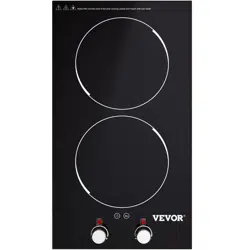
Product voltage :120V Rated power:1300 watts and 1000watts
1. Power on: power on the motherboard self-check drop a sound, digital
display dot.
2.On key: Press on key to enter standby, digital display “---”
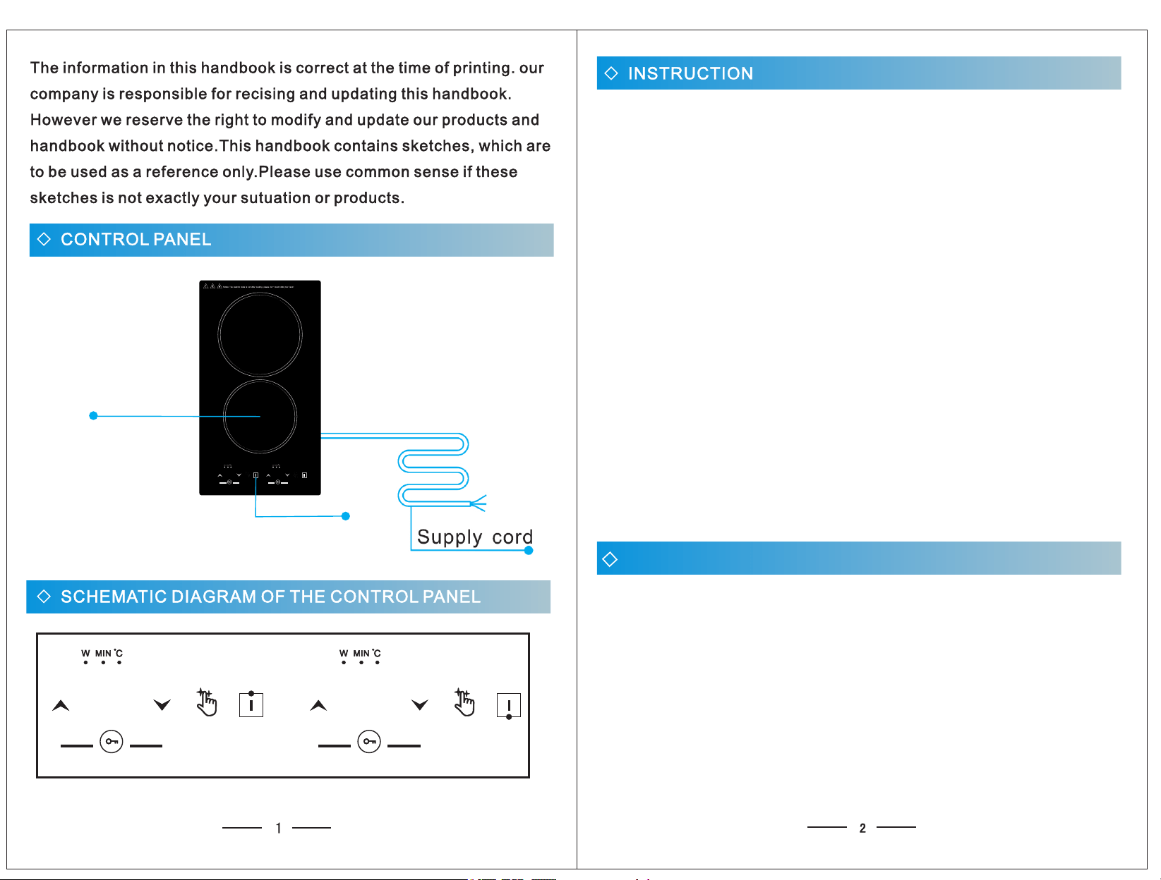
3. Function key: In standby mode, press Select to enter the heating mode.
Display as "P9", repeatedly touch the function key to adjust to:
timing/temperature gear. (W-power heating mode, MIN-timing,
℃- temperature heating mode).
4. Add and subtract keys: adjust gear/temperature/time parameters.
5. Child lock: Hold down the add and subtract keys for 2-3 seconds to lock
or unlock (LOC will be displayed after the lock is successful). The add,
subtract, and select keys of the locked state cannot be manipulated.
1) Power display: P1-P2-P3-P4-P5-P6-P7-P8- nine sections can be P9
adjusted.
2) Temperature display: 80-100-120-140-160-180-200-220- nine 240
sections can be adjusted.
3) Time: -T- -----120 minutes adjustable. Up by 5 minutes, down by 1 0
minute. Long press progressive.
Note: The red fields are the default values for startup heating.
Furnace surface high temperature: display “H.Ot”
6. Code:
E0------- no pot
E1------- The voltage is lower than 60.
E2------- Excessive voltage (voltage higher than 138)
E3------- Furnace surface overtemperature or sensor damage short circuit
E4------- Furnace surface sensor open
E5-------IGBT overtemperature or fan damage does not work
E6------- The IGBT sensor is open
E8------- The control board is connected to the main power supply board
TROUBLE CODE AND TROUBLESHOOTING
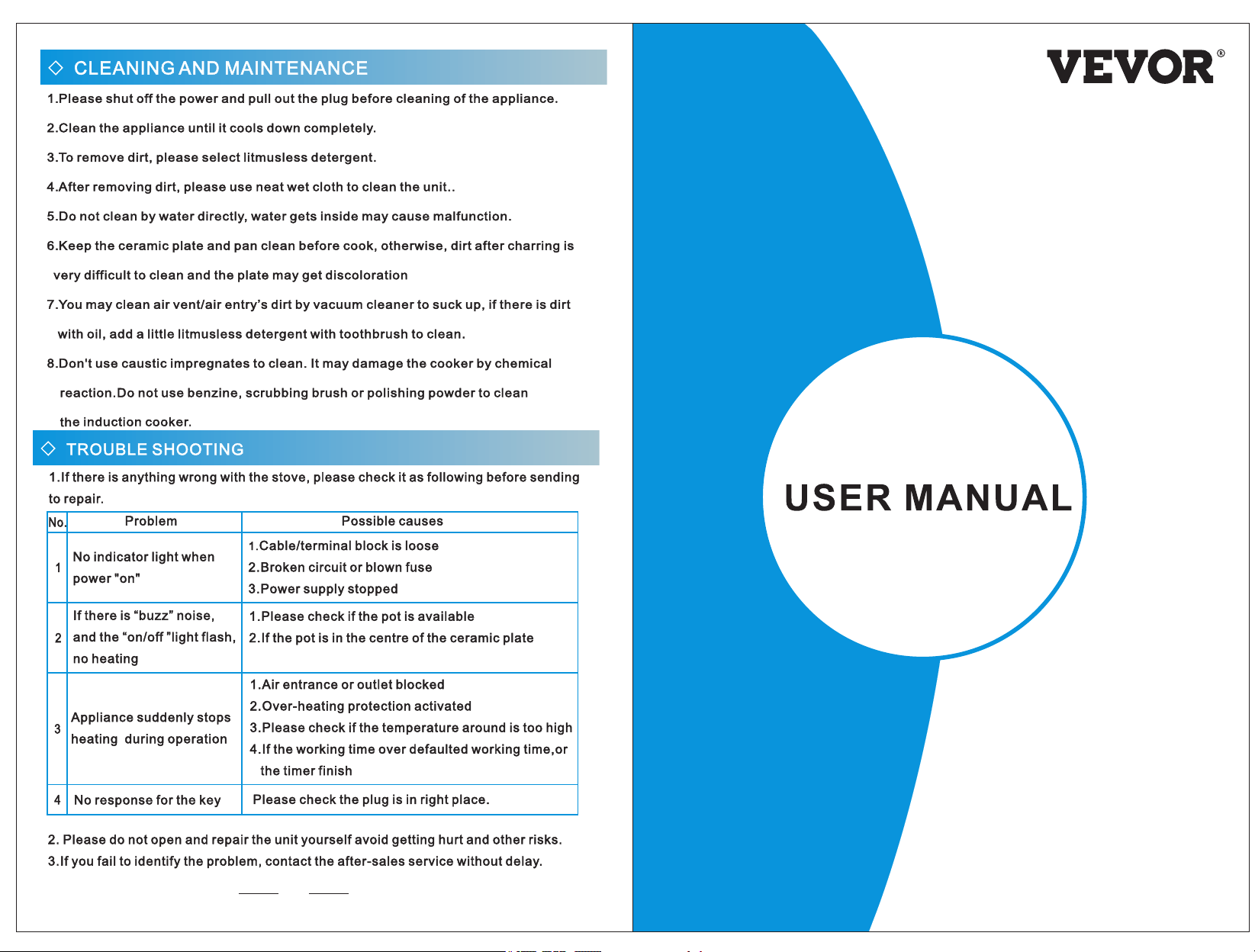
Glass plate
control panel
The above is only the schematic diagram of the structure,
please refer to the actual object.
3
4
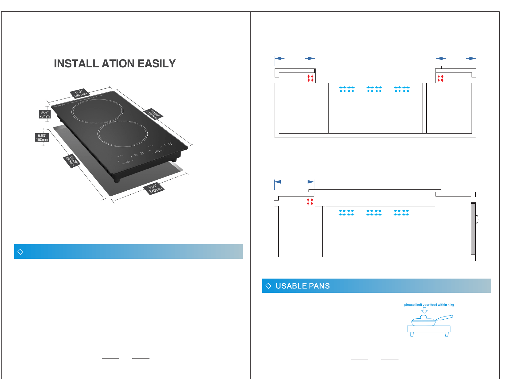
7.1. Product dimensions 288*510*78m m (11.3*20.08*3.07inches)
7.2. Opening roar size 270*490mm ( 10.6*19.29*5.90inches)
Note: if the product is used on the table, because the bottom of the use process
will produce temperature, please use high temperature resistant flame retardant
material for the table such as marble....... And so on.
When the machine is embedded, to ensure the normal use of the machine and
better heat dissipation.
Requirements:
1. 30-50mm heat dissipation should be left on the left and right sides and behind.
2. The counter interior should be as large as possible to ensure that enough cold
air is sucked into the machine.
3. Inlet air (cold air) must be separated from outlet air (hot air) space.
4. The air inlet and outlet space of the counter leave air roar.
HEAT DISSIPATION STRUCTURE INSTALLATION DRAWING
Front view
30.00 mm
30.00 mm
left
right
Induction cooker
Counter space
Heat flow
The cold air
Exhaust roar
Heat flow
Exhaust roar
30.00 mm
after
Air inlet
Cupboard door
Induction cooker
Heat flow
Exhaust roar
The cold air
Counter space
Side view
All flat bottom pots.
Please use iron pot, containing magnetic pot.
Please limit your food within 4kg.
5
6
1515