Loading ...
Loading ...

3
1
2
3
1
2
3
Use a small, at blade screwdriver to open the
access cover and fuse holder for the fuses and
to set the output voltage.
Use a small, at blade screwdriver to open the
access cover and fuse holder for the fuses and
to set the output voltage.
3. Installation
Before connecting equipment to the isolation transformer, verify the local mains voltage matches the input voltage
selected on the transformer. The output voltage must match the voltage compatible with the equipment load.
The appliance inlet of the isolation transformer (300VA, 600VA or 1000VA) is designed so power cannot be applied while
the fuse access door is opened. If this protective feature is damaged, have the appliance inlet replaced by a qualied
service person. Do not defeat this protective feature or attempt to perform inspection or replacement of fuses while the
isolation transformer is ON and plugged into mains power.
Install in accordance with applicable electrical codes, such as National Electrical Code and/or NFPA 99 Article 517. Use only with an approved
plug/cord set according to the equipment electrical ratings being used. The transformer must be installed by a qualied technician only.
Compliance with ANSI/AAMI/CSA 60601-1 / IEC 60601-1 3.1 ed. must be evaluated after the nal installation.
3.1 Select input and output voltage on the isolation transformer based on the local mains
voltage available and the voltage rating of the equipment to be connected.
3.1.1 For IS300HGDV and IS600HGDV:
Input voltage selection is made via the inlet fuse holder (Figure 1). The voltage selected will display above the power switch
A
. You will
also have to insert the correct fuse value depending on the transformer model and input voltage. For correct fuse value, see the table
in section 3.1.5. Output voltage selection is made with the selector switch
B
.
Note: If using as a step-up or step-down transformer, the output voltage must match the connected equipment load requirements.
Figure 1
Figure 2
A
A
B
B
Output Voltage
Selector Switch
Output
Voltage
Selector
Switch
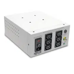
3.1.2 For IS1000HGDV:
Input voltage selection is made via the inlet fuse holder (Figure 2). The voltage selected will display above the power switch
A
. You
will also have to insert the correct fuse value depending on input voltage. For correct fuse value, see the table in section 3.1.5. Output
voltage selection is made with the selector switch
B
.
Note: If using as a step-up or step-down transformer, the output voltage must match the connected equipment load requirements.
Loading ...
Loading ...
Loading ...