perator's
I:RnFrSMRN°
LAWN TRACTOR
21 HP, Variation Speed
46" Deck
Model No. 247.28885
• Espanol, P. 58
This product has a low emission engine which operates differently
from previously built engines. Before you start the engine, read and
understand this Operator's Manual.
Before using this equipment,
read this manual and follow
all safety rules and operating
instructions.
For answers to your questions about
this product, Call:
1-800=659=5917
Craftsman Tractor Help Line
7 am = 7 pm CT, Mort. =Sun.
Sears Brands Management Corporation, Hoffman Estates, IL 60179 U.S.A.
Visit our website: www.craftsman.com FormNo.769-06474
(November15,2010)
Off-Season Storage ........................................................ 27
Trou bleshooting .............................................................. 28
Labels ............................................................................. 29
Parts List ......................................................................... 30
Espafiol ............................................................................ 58
Service Numbers ............................................. Back Cover
CRAFTSMAN TWO YEAR FULL WARRANTY
FORTWOYEARSfromthedate of purchase,if anynon-expendablepart of this ridingequipmentfailsdue to a defect inmaterialor workman-
ship,visit www.craftsman.com or call 1-800-659-5917to arrangefor free in-homerepair.
Theframeandfront axle will berepairedfreeof chargefor fiveyears from thedate of purchaseif defectiveinmaterialorworkmanship.
In all cases, ifrepairprovesimpossible,the ridingequipmentwill be replacedfree of chargewiththe sameoran equivalentmodel.
Thebatterywill be replacedfree of chargefor 90 daysfromthe dateof purchaseif defectiveinmaterialor workmanship(our testingprovesthat it
willnot hold a charge).
Thiswarrantyisvoidif this productiseverusedwhile providingcommercialservicesorif rentedto anotherperson.
This warranty covers ONLYdefects in materialand workmanship. Warranty coverage does NOTinclude:
• Expendableitemsthatcanwearout fromnormalusewithinthe warrantyperiod,includingbut not limitedto blades,sparkplugs,air
cleaners,belts,andoil filters.
• Standardmaintenanceservicing,oilchanges,or tune-ups.
Tire replacementor repaircausedby puncturesfrom outsideobjects,such as nails,thorns,stumps,or glass.
Tireorwheel replacementor repairresultingfromnormalwear,accident,or improperoperationor maintenance.
Repairsnecessarybecauseof operatorabuse, includingbutnot limitedto damagecausedby towingobjectsbeyondthecapabilityof
the ridingequipment,impactingobjectsthatbendthe frameor crankshaft,or over-speedingtheengine.
Repairsnecessarybecauseof operatornegligence,includingbut not limitedto, electricaland mechanicaldamagecausedbyimproper
storage,failureto usethe propergradeand amountof engineoil, failureto keepthe deckclear of flammabledebris,or failureto
maintainthe ridingequipmentaccordingto the instructionscontainedinthe operator'smanual.
• Engine(fuelsystem)cleaningor repairscausedby fuel determinedto becontaminatedor oxidized(stale).In general,fuel shouldbe
usedwithin30 daysof itspurchasedate.
Normaldeteriorationandwearof the exteriorfinishes,or productlabelreplacement.
Thiswarrantygivesyou specificlegal rights,and you mayalso haveotherrightswhich vary from stateto state.
Sears Brands ManagementCorporation, HoffmanEstates, IL 60179
EngineOil: SAE30
Fuel: UnleadedGasoline
SparkPlug: Champion®RC12YC
Engine: Briggs& Stratton
Model Number:
Serial Number:
Dateof Purchase:
Recordthe modelnumber,serialnumber,
anddateof purchaseabove.
© KCD IR LLC 2

Thissymbolpointsout importantsafetyinstructionswhich,if not
followed,couldendangerthepersonalsafetyand/orpropertyof
yourselfandothers. Readandfollowall instructionsin thismanual
beforeattemptingto operatethis machine.Failureto complywith
theseinstructionsmayresultin personalinjury.Whenyou seethis
symbol,HEEDITSWARNING!
CALIFORNIA PROPOSITION 65
EngineExhaust,someof itsconstituents,andcertainvehicle
componentscontainoremit chemicalsknownto Stateof California
to cause cancerand birthdefects or other reproductiveharm.
Batteryposts,terminals,and relatedaccessoriescontainleadand
leadcompounds,chemicalsknownto the Stateof Californiato
causecancerand reproductiveharm.Washhandsafterhandling.
Thismachinewasbuiltto beoperatedaccordingto the safeopera-
tion practicesin this manual.As withanytypeof powerequipment,
carelessnessorerroron the partof the operatorcan resultin serious
injury.Thismachineis capableof amputatingfingers,hands,toes
andfeet and throwingdebris.Failureto observethe followingsafety
instructionscouldresultin seriousinjuryor death.
Your Responsibility--Restrictthe use of thispowermachineto
personswho read,understandand follow thewarningsand instruc-
tionsin this manualand on the machine.
SAVE THESE INSTRUCTIONS!
GENERAL OPERATION
• Read,understand,andfollowall instructionson the machineand
in themanual(s)beforeattemptingto assembleand operate.
Keepthis manualin a safe placefor futureand regularreference
andfor orderingreplacementparts.
• Befamiliarwithall controlsandtheir properoperation.Knowhow
to stop the machineanddisengagethemquickly.
• Neverallowchildrenunder14yearsoldto operatethis machine.
Children14yearsoldand over shouldreadandunderstandthe
operationinstructionsandsafetyrulesinthismanualand should
betrainedand supervisedbya parent.
• Neverallowadultsto operatethis machinewithoutproper
instruction.
• Tohelpavoidbladecontactor a thrownobjectinjury,keep
bystanders,helpers,childrenandpetsat least 75 feet fromthe
machinewhile it is in operation.Stopmachineif anyoneenters
the area.
• Thoroughlyinspectthe areawherethe equipmentis to be used.
Removeallstones,sticks,wire,bones,toys,and otherforeign
objectswhich couldbe pickedup and thrownby the blade(s).
Thrownobjectscan causeseriouspersonalinjury.
• Planyour mowingpatternto avoiddischargeof materialtoward
roads,sidewalks,bystandersandthe like.Also, avoiddischarg-
ingmaterialagainstawall orobstructionwhichmaycause
dischargedmaterialto ricochetbacktowardthe operator.
• Alwayswear safetyglassesor safetygogglesduring operation
andwhile performingan adjustmentor repairto protectyoureyes.
Thrownobjectswhichricochetcancauseseriousinjuryto the
eyes.
• Wearsturdy,rough-soledwork shoesandclose-fittingslacksand
shirts.Loosefittingclothesand jewelry canbe caughtin movable
parts.Neveroperatethismachineinbarefeetor sandals.
• Be awareof the mowerand attachmentdischargedirectionand
do not pointit at anyone.Donot operatethe mowerwithoutthe
dischargecoverorentiregrasscatcherin its properplace.
Donot put handsor feetnearrotatingpartsor underthe cutting
deck. Contactwith the blade(s)can amputatehandsand feet.
A missingor damageddischargecovercan causeblade contact
or thrownobjectinjuries.
• Stoptheblade(s)whencrossinggraveldrives,walks,or roads
andwhile notcuttinggrass.
• Watchfor trafficwhenoperatingnear or crossingroadways.This
machineis not intendedfor useon any public roadway.
• Donot operatethe machinewhile underthe influenceof alcohol
or drugs.
• Mowonly indaylightorgoodartificiallight.
Nevercarrypassengers.
• Disengageblade(s)beforeshiftinginto reverse.Backup slowly.
Alwayslookdownandbehindbeforeand while backingto avoida
back-overaccident.
3
• Slowdownbeforeturning.Operatethe machinesmoothly.Avoid
erraticoperationand excessivespeed.
Disengageblade(s),setparkingbrake,stopengineand wait until
the blade(s)come to a completestop beforeremovinggrass
catcher,emptyinggrass,uncloggingchute,removinganygrassor
debris,or makinganyadjustments.
Neverleavea runningmachineunattended.Alwaysturnoff
blade(s),setparkingbrake,stopengine and removekey before
dismounting.
Useextracare whenloadingor unloadingthe machineintoa
trailerortruck.Thismachineshouldnot bedrivenupor down
ramp(s),becausethe machinecouldtip over,causingserious
personalinjury.The machinemustbe pushedmanuallyon
ramp(s)to loador unloadproperly.
Mufflerandenginebecomehotand can causea burn.Do not
touch.
Checkoverheadclearancescarefullybeforedrivingunderlow
hangingtree branches,wires,door openingsetc., wherethe
operatormay be struckor pulledfrom the machine,whichcould
resultinseriousinjury.
Disengageallattachmentclutchesanddepressthe brakepedal
completelybeforeattemptingto start engine.
Yourmachineisdesignedto cut normalresidentialgrass of a
heightnomorethan 10".Do not attemptto mowthroughunusually
tall,dry grass (e.g.,pasture)or piles of dry leaves.Dry grass or
leavesmaycontactthe engineexhaustand/or buildup on the
mowerdeckpresentinga potentialfire hazard.
Useonlyaccessoriesandattachmentsapprovedfor this machine
by the machinemanufacturer.Read,understandandfollowall
instructionsprovidedwiththe approvedaccessoryor attachment.
Fora list of approvedaccessoriesandattachments,call 1-800-
659-5917.
Dataindicatesthatoperators,age 60 years and above,are
involvedin a largepercentageof riding mower-relatedinjuries.
Theseoperatorsshouldevaluatetheirabilityto operatethe riding
mowersafelyenoughto protectthemselvesandothersfrom
seriousinjury.
If situationsoccurwhicharenot coveredin this manual,usecare
andgoodjudgment.Contact1-800-659-5917for informationand
assistance.
SLOPE OPERATION
Slopesarea majorfactorrelatedto loss of controlandtip-over
accidentswhichcan result in severeinjuryor death.All slopesrequire
extracaution.If youcannot back up the slopeor if youfeel uneasyon
it, do not mowit.
Foryoursafety,use the SlopeGuideincludedas partof this manual
to measureslopesbeforeoperatingthis machineona slopedor hilly
area. If the slopeis greaterthan15 degreesas shownonthe Slope
Guide,do notoperatethis machineonthat area or seriousinjurycould
result.
Do:
o
Mowupand down slopes,not across.Exerciseextremecaution
whenchangingdirectionon slopes.
• Watchfor holes,ruts,bumps,rocks,orother hiddenobjects.
Uneventerraincouldoverturnthe machine.Tallgrass can hide
obstacles.
Useslowspeed.Choosea lowenoughspeedsettingso that
you will nothaveto stop or shiftwhileon the slope.Tiresmay
lose tractionon slopeseventhoughthe brakesare functioning
properly.Alwayskeepmachinein gearwhen goingdownslopes
to take advantageof enginebrakingaction.
• Followthe manufacturer'srecommendationsfor wheelweights
or counterweightsto improvestability.Forrecommendations,call
1-800-659-5917.
• Useextra carewith grass catchersor otherattachments.These
can changethe stabilityof the machine.
Keepallmovementonthe slopesslowandgradual.Do not make
suddenchangesinspeedor direction.Rapidengagementor
brakingcouldcausethe front of the machineto lift andrapidlyflip
overbackwardswhichcouldcauseseriousinjury.
• Avoidstartingorstoppingona slope.Iftireslosetraction,disen-
gagethe blade(s)andproceedslowlystraightdownthe slope.
DoNot:
• Donot turnon slopesunlessnecessary;then,turnslowlyand
graduallydownhill,if possible.
• Donot mowneardrop-offs,ditchesor embankments.The mower
could suddenlyturnover if a wheelis overthe edgeof a cliff,
ditch,or if an edge cavesin.
• Donot try to stabilizethe machineby puttingyourfooton the
ground.
• Donot usea grasscatcheron steepslopes.
• Donot mowon wetgrass.Reducedtractioncouldcausesliding.
• Donot attemptto coastdownhill.Over-speedingmaycausethe
operatorto lose controlof the machineresultingin seriousinjury
or death.
• Donot towheavypull behindattachments(e.g.loadeddumpcart,
lawn roller,etc.)on slopesgreaterthan5 degrees.Whengoing
down hill,the extraweighttendsto pushthe tractorandmay
causeyou to loosecontrol(e.g.tractormay speedup, brakingand
steeringabilityare reduced,attachmentmayjack-knifeandcause
tractorto overturn).
4

CHILDREN
Tragicaccidentscanoccurifthe operatoris notalert to the presence
of children.Childrenare often attractedto the machineand the mowing
activity.Theydo notunderstandthe dangers.Neverassumethat
childrenwill remainwhereyou lastsawthem.
• Keepchildrenout of the mowingareaand inwatchfulcare of a
responsibleadultotherthanthe operator.
• Bealert and turnmachineoff ifa childentersthe area.
• Beforeandwhilebacking,lookbehindanddownfor small
children.
Nevercarrychildren,evenwiththe blade(s)shut off.They may
fall off and be seriouslyinjuredorinterferewithsafemachine
operation.
• Useextremecarewhenapproachingblind corners,doorways,
shrubs,treesor otherobjectsthat may block yourvisionof a child
whomayrunintothe machine.
Toavoidback-overaccidents,alwaysdisengagethe cutting
blade(s)beforeshiftingintoReverse.Ifequipped,the "Reverse
CautionMode"(bladesoperatewhilemachineridesinreverse)
shouldnotbe usedwhenchildrenor othersarearound.
Keepchildrenaway from hotor runningengines.They cansuffer
burnsfroma hotmuffler.
• Removekeywhenmachineisunattendedto preventunauthorized
operation.
Neverallowchildrenunder14yearsof ageto operatethis machine.
Children14andovershouldreadand understandthe instructionsand
safeoperationpracticesinthismanualand on the machineandshould
betrainedand supervisedbyan adult.
TOWING
Towonlywitha machinethathasa hitch designedfor towing.Do
not attachtowedequipmentexceptat the hitch point.
Followthe manufacturersrecommendationforweightlimitsfor
towedequipmentandtowingon slopes.For recommendations,
call 1-800-659-5917.
Neverallowchildrenor othersinoron towedequipment.
Onslopes,theweightof thetowedequipmentmaycause lossof
tractionandloss of control.
Alwaysuseextracautionwhentowingwitha machinecapableof
makingtightturns (e.g."zero-turn"ride-onmower). Makewide
turnsto avoidjack-knifing.
Travelslowlyandallowextradistanceto stop.
Do notcoastdownhill.
SERVICE
SafeHandlingof Gasoline
Toavoidpersonalinjuryorpropertydamageuse extremecarein
handlinggasoline.Gasolineisextremelyflammableandthe vaporsare
explosive.Seriouspersonalinjurycanoccurwhengasolineis spilled
on yourselfor your clotheswhichcan ignite.Washyourskinand
changeclothesimmediately.
• Useonly anapprovedgasolinecontainer.
Neverfill containersinsidea vehicleor on a truckor trailer bed
witha plasticliner.Alwaysplacecontainerson the groundaway
fromyourvehiclebeforefilling.
Whenpractical,removegas-poweredequipmentfromthe truck
or trailerandrefueliton theground.Ifthis isnot possible,then
refuelsuchequipmentona trailerwitha portablecontainer,rather
than froma gasolinedispensernozzle.
Keepthe nozzleincontactwith the rim of the fueltank or
containeropeningat all timesuntilfuelingiscomplete.Donot use
a nozzlelock-opendevice.
Extinguishall cigarettes,cigars,pipesandothersourcesof
ignition.
• Neverfuel machineindoors.
Neverremovegascap or add fuelwhilethe engineis hotor run-
ning.Allowengineto coolat least two minutesbeforerefueling.
Neveroverfill fuel tank. Filltank to no morethan 1/2inchbelow
bottomof filler neckto allowspaceforfuel expansion.
• Replacegasolinecap andtightensecurely.
• If gasolineis spilled,wipeitoff the engineand equipment.Move
machineto anotherarea.Wait 5 minutesbeforestartingthe
engine.
• To reducefire hazards,keepmachinefree of grass,leaves,or
otherdebrisbuild-up.Cleanup oilor fuel spillageand removeany
fuel soakeddebris.
• Neverstorethe machineor fuelcontainerinsidewherethere isan
openflame,sparkor pilotlight as ona waterheater,spaceheater,
furnace,clothesdryeror othergasappliances.
Allowa machineto coolat least five minutesbeforestoring.
GeneralService
• Neverrunanengineindoorsorinapoorlyventilatedarea.Engine
exhaustcontainscarbonmonoxide,anodorless,anddeadlygas.
• Beforecleaning,repairing,orinspecting,makecertainthe
blade(s)andallmovingpartshavestopped.Disconnectthespark
plugwireandgroundagainsttheenginetopreventunintended
starting.
• Periodicallychecktomakesurethebladescometocomplete
stopwithinapproximately(5)fivesecondsafteroperatingthe
bladedisengagementcontrol.Ifthebladesdonotstopwithinthe
thistimeframe,yourmachineshouldbeservicedprofessionally
byaSearsorotherqualifiedservicedealer.
• Checkbrakeoperationfrequentlyasitissubjectedtowearduring
normaloperation.Adjustandserviceasrequired.
• Checktheblade(s)andenginemountingboltsatfrequent
intervalsforpropertightness.Also,visuallyinspectblade(s)
fordamage(e.g.,excessivewear,bent,cracked).Replacethe
blade(s)withtheoriginalequipmentmanufacturer's(O.E.M.)
blade(s)only,listedinthismanual.Useofpartswhichdonot
meettheoriginalequipmentspecificationsmayleadtoimproper
performanceandcompromisesafety!
• Mowerbladesaresharp.Wrapthebladeorweargloves,anduse
extracautionwhenservicingthem.
• Keepallnuts,bolts,andscrewstighttobesuretheequipmentis
insafeworkingcondition.
• Nevertamperwiththe safetyinterlocksystemor othersafety
devices.Checktheir properoperationregularly.
• Afterstrikinga foreignobject,stopthe engine,disconnectthe
sparkplugwire(s)and groundagainstthe engine.Thoroughly
inspectthe machinefor anydamage.Repairthe damagebefore
startingandoperating.
• Neverattemptto makeadjustmentsor repairsto the machine
whilethe engineis running.
• Grasscatchercomponentsandthe dischargecoverare subject
to wearand damagewhich couldexposemovingparts or allow
objectsto be thrown.Forsafetyprotection,frequentlycheck
componentsand replaceimmediatelywithoriginalequipment
manufacturer's(O.E.M.)parts only,listedinthis manual.Useof
partswhichdo not meetthe originalequipmentspecificationsmay
leadto improperperformanceandcompromisesafety!
• Donot changethe enginegovernorsettingsor over-speedthe
engine.The governorcontrolsthe maximumsafeoperatingspeed
of the engine.
Maintainor replacesafetyandinstructionlabels,as necessary.
• Observeproperdisposallawsandregulationsfor gas, oil, etc.to
protecttheenvironment.
• Accordingto the ConsumerProductsSafetyCommission(CPSC)
andthe U.S.EnvironmentalProtectionAgency(EPA),this product
has an AverageUsefulLifeof seven(7)years,or 270hours
of operation.At the end of the AverageUsefulLife,buy anew
machineor havethe machineinspectedannuallybya Searsor
otherqualifiedservicedealerto ensurethat all mechanicaland
safetysystemsareworkingproperlyand not wornexcessively.
Failureto do so can resultin accidents,injuriesor death.
DO NOT MODIFY ENGINE
Toavoid seriousinjuryor death,do notmodifyengine in anyway.
Tamperingwiththe governorsettingcanlead to a runawayengineand
causeit to operateat unsafespeeds.Nevertamper with factorysetting
of enginegovernor.
NOTICE REGARDING EMISSIONS
Engineswhicharecertifiedto complywithCaliforniaandfederal
EPAemissionregulationsfor SORE(SmallOff RoadEquipment)are
certifiedto operateon regularunleadedgasoline,and may include
the followingemissioncontrol systems:EngineModification(EM)and
ThreeWayCatalyst(TWO)if so equipped.
SPARK ARRESTOR
Thismachineis equippedwith an internalcombustionengineand
shouldnotbe usedonor nearanyunimprovedforest-covered,
brushcoveredorgrass-coveredlandunlessthe engine'sexhaust
systemisequippedwitha sparkarrestormeetingapplicablelocalor
statelaws(if any).
Ifa sparkarrestoris used,it shouldbe maintainedin effectiveworking
orderby the operator.Inthe Stateof Californiatheaboveis required
by law (Section4442of the CaliforniaPublicResourcesCode). Other
statesmayhavesimilarlaws.Federallawsapplyonfederallands.
A sparkarrestorfor the muffleris availablethroughyournearestSears
PartsandRepairServiceCenter.
6
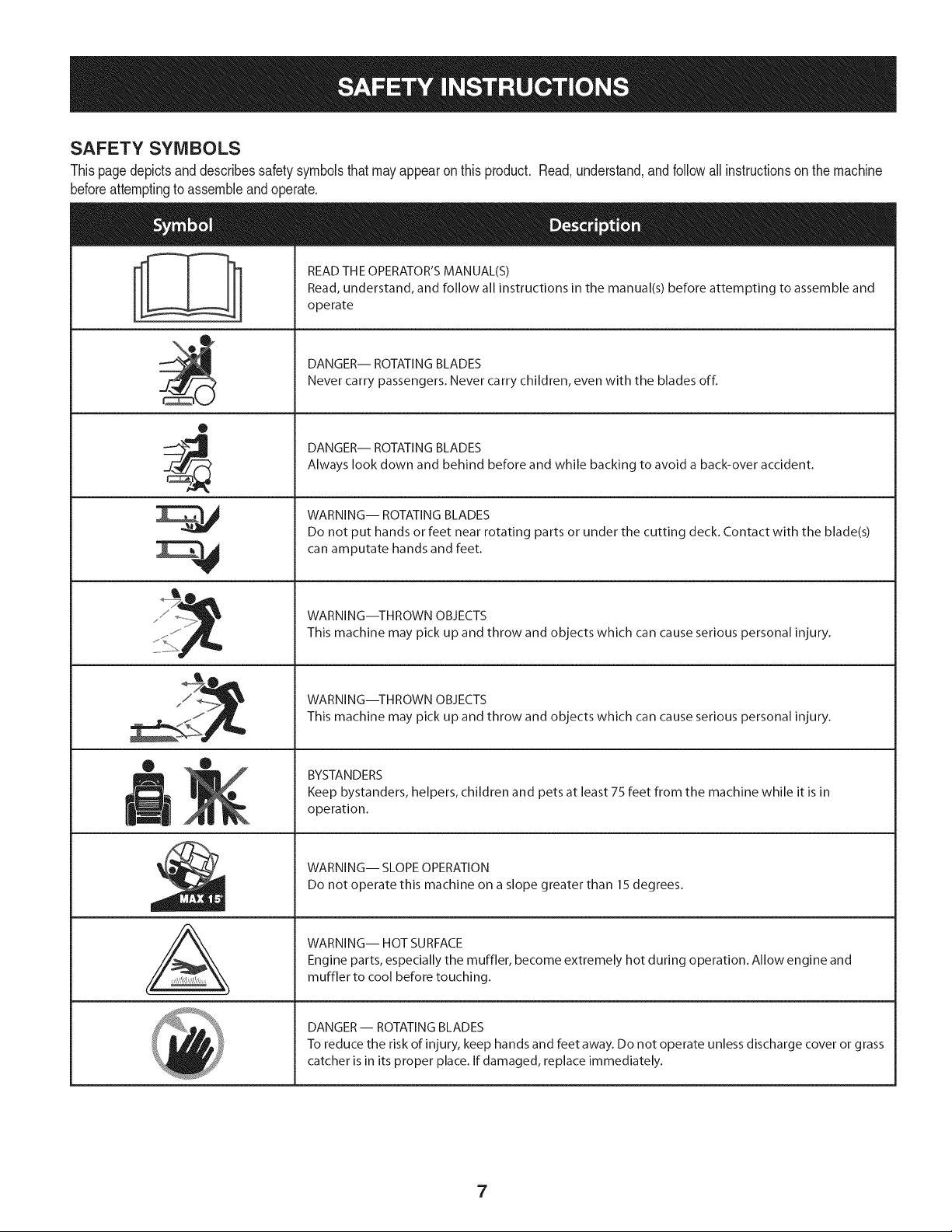
SAFETY SYMBOLS
Thispagedepictsanddescribessafety symbolsthat may appearon this product. Read,understand,andfollowallinstructionson the machine
beforeattemptingto assembleand operate.
O
A
READ THE OPERATOR'S MANUAL(S)
Read, understand, and follow all instructions in the manual(s) before attempting to assemble and
operate
DANGER-- ROTATING BLADES
Never carry passengers. Never carry children, even with the blades off.
DANGER-- ROTATING BLADES
Always look down and behind before and while backing to avoid a back-over accident.
WARNING-- ROTATING BLADES
Do not put hands or feet near rotating parts or under the cutting deck. Contact with the blade(s)
can amputate hands and feet.
WARNING--THROWN OBJECTS
This machine may pick up and throw and objects which can cause serious personal injury.
WARNING--THROWN OBJECTS
This machine may pick up and throw and objects which can cause serious personal injury.
BYSTANDERS
Keep bystanders, helpers, children and pets at least 75 feet from the machine while it is in
operation.
WARNING-- SLOPE OPERATION
Do not operate this machine on a slope greater than 15 degrees.
WARNING-- HOT SURFACE
Engine parts, especially the muffler, become extremely hot during operation. Allow engine and
muffler to cool before touching.
DANGER- ROTATING BLADES
To reduce the risk of injury, keep hands and feet away. Do not operate unless discharge cover or grass
catcher is in its proper place. If damaged, replace immediately.
7
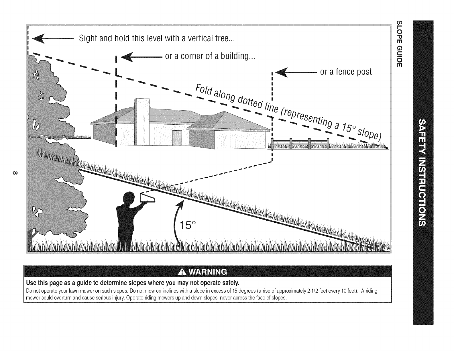
0o
Sight and hold this levelwith a vertical tree...
or a corner of a building...
15 °
Use this page as a guide to determine slopes where you may not operate safely.
Donot operateyourlawnmoweron such slopes.Do notmowon inclineswitha slope in excessof 15degrees(a rise of approximately2-1/2feetevery 10feet). A riding
mowercouldoverturnand causeseriousinjury.Operateriding mowersup and downslopes,neveracrossthe faceof slopes.
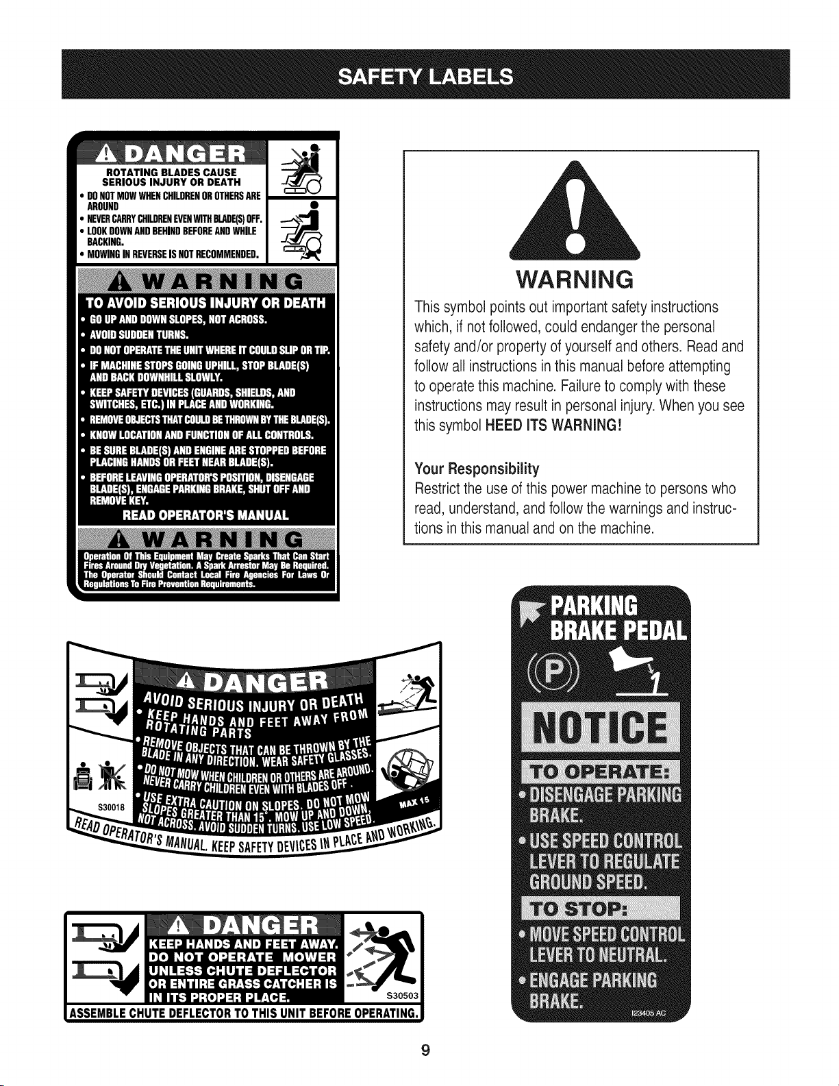
ROTATING BLADES CAUSE
SERIOUS INJURY OR DEATH
DONOTMOWWHENCHILDRENOROTHERSARE
AROUND
NEVERCARRYCHILDRENEVENWITHBLADE(S)OFF.
LOOKDOWNANDBEHINDBEFOREANDWHILE
BACKING.
MOWINGINREVERSEISNOTRECOMMENDED.
WARNING
This symbol points out important safety instructions
which, if notfollowed, could endangerthe personal
safety and/or property of yourself and others. Read and
follow all instructions inthis manual before attempting
to operatethis machine. Failure to comply with these
instructions may result in personal injury.When you see
this symbol HEED ITS WARNING!
Your Responsibility
Restrictthe use of this power machineto persons who
read, understand, and follow the warnings and instruc-
tions in this manual and on the machine.
9
IMPORTANT:Yourtractoris shippedwithmotoroil in theengine.
However,you MUSTcheckthe oil levelbeforeoperating.Referto the
Service& Maintenancesectionfor instructionson checkingtheoil
level.
Attaching the Battery Cables
CALIFORNIA PROPOSITION 65
Batteryposts,terminals,and relatedaccessoriescontainleadand
leadcompounds,chemicalsknownto the Stateof Californiato
causecancerand reproductiveharm.Washhandsafter handling.
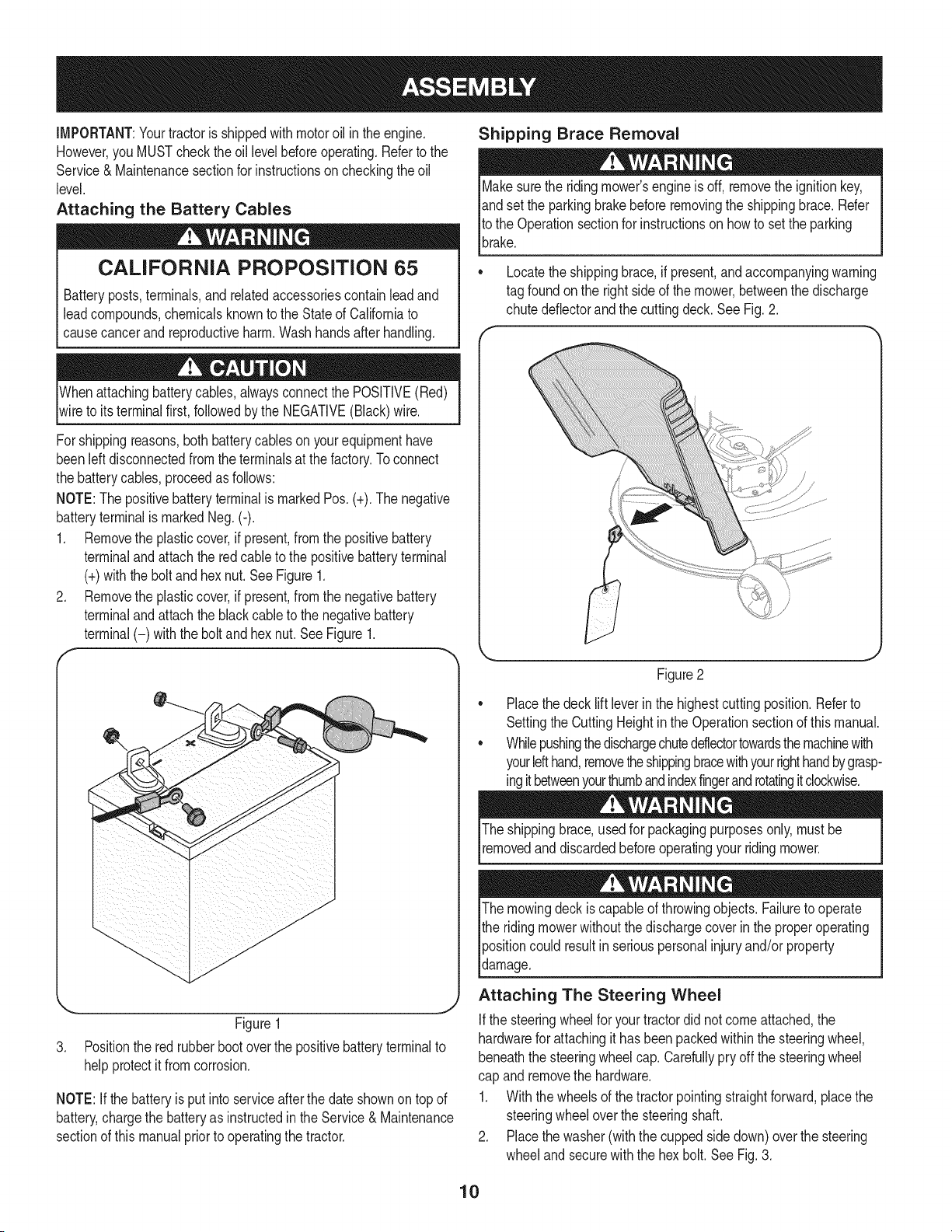
Whenattachingbatterycables,alwaysconnectthe POSITIVE(Red)
wireto its terminalfirst, followedby the NEGATIVE(Black)wire.
Forshippingreasons,bothbatterycablesonyourequipmenthave
beenleft disconnectedfrom the terminalsat the factory.Toconnect
the batterycables,proceedas follows:
NOTE:Thepositivebatteryterminalis markedPos. (+).The negative
batteryterminalis markedNeg.(i).
1. Removethe plasticcover,if present,fromthe positivebattery
terminaland attachthe redcableto the positivebatteryterminal
(+)withthe bolt andhexnut.See Figure1.
2. Removethe plasticcover,if present,fromthe negativebattery
terminaland attachthe black cableto the negativebattery
terminal(-) withthe bolt andhex nut.SeeFigure1.
f
J
Figure1
3. Positionthe red rubberbootoverthe positivebatteryterminalto
helpprotectit fromcorrosion.
NOTE:If thebatteryis put into serviceafter the dateshownon topof
battery,chargethe batteryas instructedin the Service& Maintenance
sectionof this manualpriorto operatingthe tractor.
Shipping Brace Removal
Makesurethe ridingmower'sengineis off, removetheignitionkey,
andset the parkingbrakebeforeremovingthe shippingbrace. Refer
Itothe Operationsectionfor instructionson howto set the parking
lbrake.
• Locatethe shippingbrace,if present,and accompanyingwarning
tag foundon the rightsideof the mower,betweenthe discharge
chutedeflectorand the cuttingdeck. See Fig. 2.
Figure2
Placethe deck lift leverin the highestcuttingposition.Referto
SettingtheCuttingHeightin the Operationsectionof thismanual.
Whilepushingthedischargechuteddlectortowardsthemachinewith
yourlefthand,removetheshippingbracewithyourrighthandbygrasp-
ingitbetweenyourthumbandindexfingerandrotatingitclockwise.
The shippingbrace,usedfor packagingpurposesonly,mustbe
removedand discardedbeforeoperatingyour ridingmower.
The mowingdeck iscapableof throwingobjects.Failureto operate
the ridingmowerwithoutthe dischargecoverin the properoperating
Ipositioncould resultin seriouspersonalinjuryand/orproperty
ldamage.
Attaching The Steering Wheel
Ifthe steeringwheelfor yourtractordid notcomeattached,the
hardwarefor attachingit has beenpackedwithinthe steeringwheel,
beneaththe steeringwheelcap.Carefullypry off the steeringwheel
cap and removethe hardware.
1. Withthe wheelsof the tractorpointingstraightforward,placethe
steeringwheeloverthe steeringshaft.
2. Placethe washer(withthe cuppedsidedown)overthe steering
wheeland securewiththe hex bolt.SeeFig.3.
10
f..-
\
Figure3
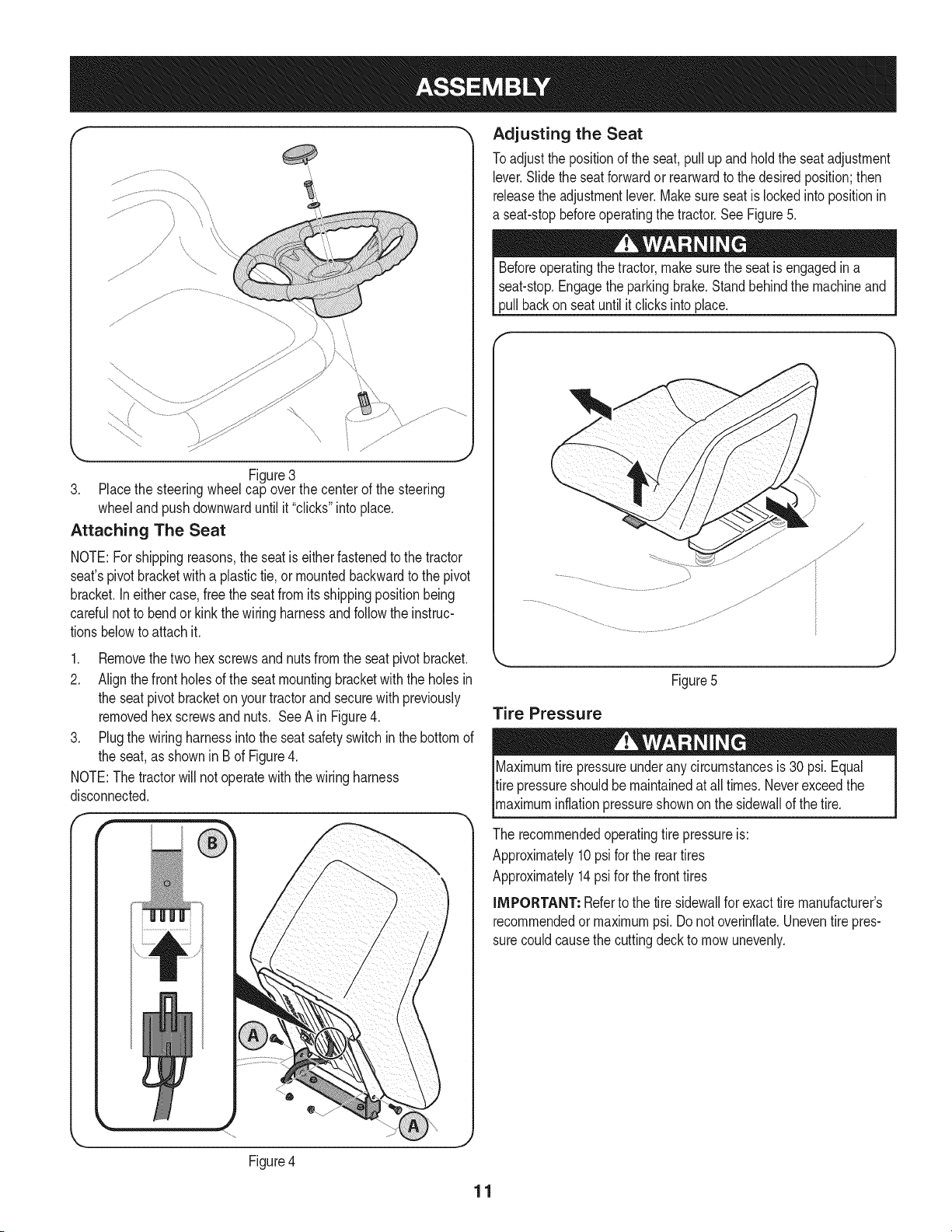
3. Placethe steeringwheelcap overthe centerof the steering
wheeland pushdownwarduntilit "clicks"intoplace.
Attaching The Seat
NOTE:Forshippingreasons,the seat is eitherfastenedtothe tractor
seat'spivotbracketwitha plastictie,or mountedbackwardto the pivot
bracket.Ineithercase,free the seatfromits shippingpositionbeing
carefulnotto bendor kinkthe wiringharnessandfollowtheinstruc-
tionsbelowto attach it.
1. Removethetwo hexscrewsandnuts fromthe seatpivotbracket.
2. Alignthefront holesof the seat mountingbracketwith the holesin
the seat pivotbracketon yourtractorand securewith previously
removedhex screwsand nuts. See A in Figure4.
3. Plugthe wiringharnessintothe seatsafetyswitch in the bottomof
the seat,as shownin Bof Figure4.
NOTE:The tractorwill not operatewith the wiringharness
disconnected.
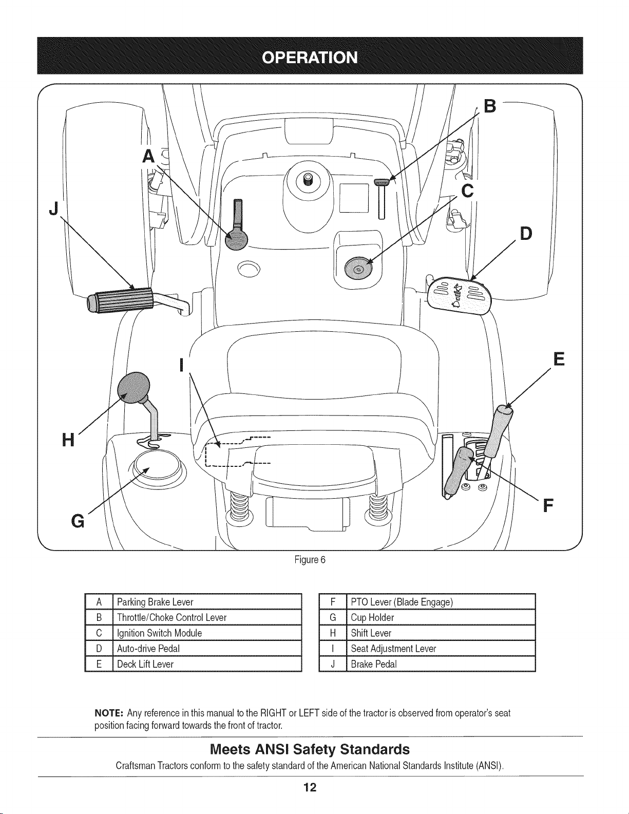
Adjusting the Seat
Toadjustthe positionof the seat,pullupand hold the seatadjustment
lever.Slidethe seatforwardor rearwardto thedesiredposition;then
releasethe adjustmentlever.Makesure seatis lockedintopositionin
a seat-stopbeforeoperatingthe tractor.See Figure5.
Beforeoperatingthe tractor,makesurethe seatis engagedin a
seat-stop.Engagethe parkingbrake.Standbehindthe machineand
pull backon seatuntil it clicksintoplace.
Figure5
Tire Pressure
Maximumtire pressureunderany circumstancesis 30 psi. Equal
tire pressureshouldbe maintainedat all times.Neverexceedthe
_maxmum nfat on pressureshownon the s dewa of thet re.
The recommendedoperatingtire pressureis:
Approximately10psi forthe reartires
Approximately14psifor the fronttires
iMPORTANT: Referto the tire sidewallfor exacttire manufacturer's
recommendedormaximumpsi.Donot overinfiate.Uneventirepres-
surecouldcausethe cuttingdeckto mowunevenly.
Figure4
11
B
C
D
E
G
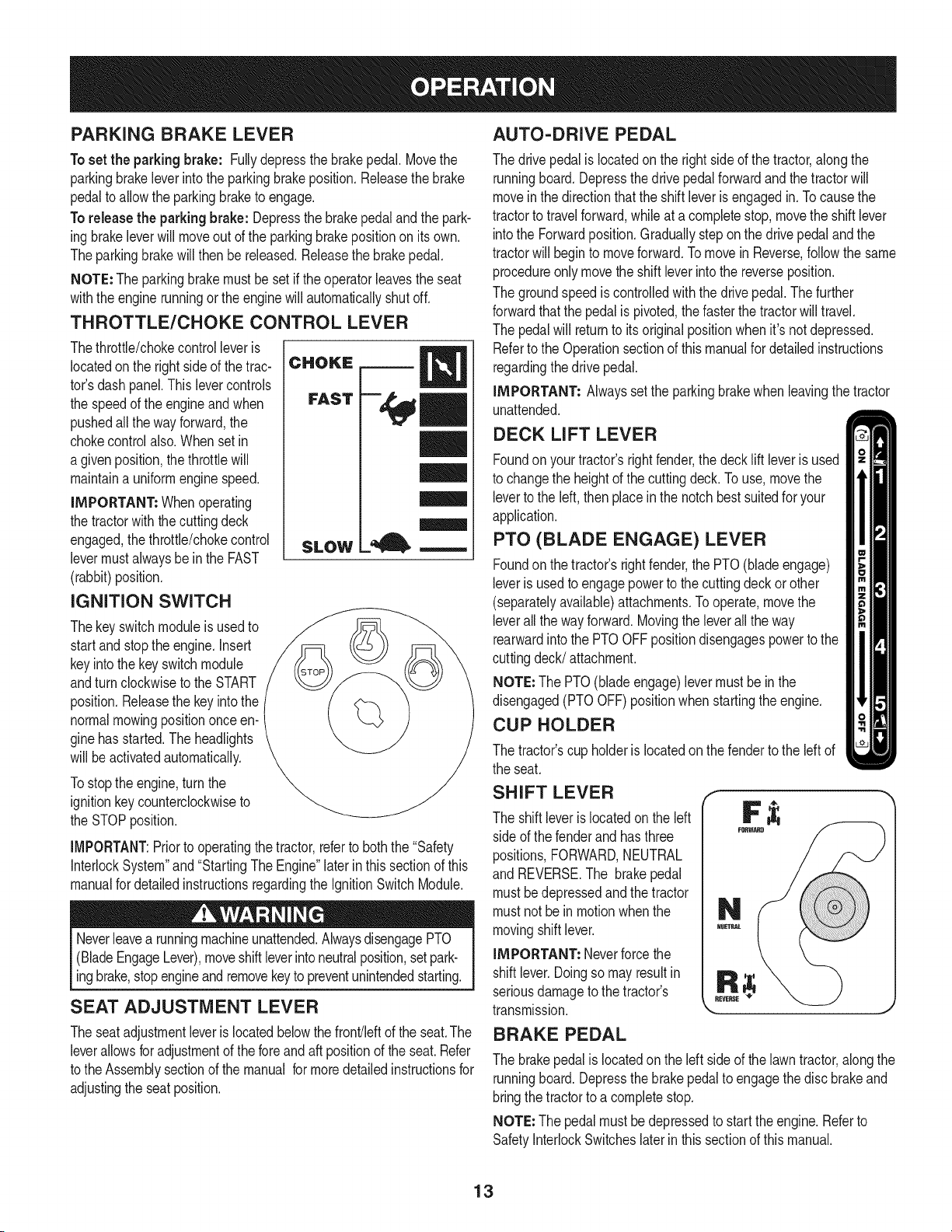
Figure6
F
J
A ParkingBrakeLever
B Throttle/ChokeControlLever
C IgnitionSwitchModule
D Auto-drivePedal
E DeckLift Lever
F PTOLever(BladeEngage)
G Cup Holder
H ShiftLever
I SeatAdjustmentLever
J BrakePedal
NOTE: Any referencein thismanualto the RIGHTor LEFTsideof the tractoris observedfromoperator'sseat
positionfacingforwardtowardsthe frontof tractor.
Meets ANSi Safety Standards
CraftsmanTractorsconformto the safetystandardof theAmericanNationalStandardsInstitute(ANSI).
12
PARKING BRAKE LEVER
Toset the parkingbrake: Fullydepressthe brakepedal. Movethe
parkingbrakeleverintothe parkingbrakeposition.Releasethe brake
pedalto allowthe parkingbraketo engage.
To release the parkingbrake: Depressthe brakepedalandthe park-
ingbrakeleverwill moveoutof the parkingbrakepositionon itsown.
Theparkingbrakewillthen be released.Releasethe brakepedal.
NOTE: The parkingbrakemustbe setif the operatorleavesthe seat
withthe enginerunningor the enginewill automaticallyshutoff.
THROTTLE/CHOKE CONTROL LEVER
Thethrottle/chokecontrolleveris
locatedonthe right sideof the trac-
tor'sdash panel.This levercontrols
the speedof the engineand when
pushedall theway forward,the
chokecontrolalso.Whenset in
a givenposition,thethrottlewill
maintaina uniformenginespeed.
IMPORTANT: Whenoperating
the tractorwith the cuttingdeck
engaged,thethrottle/chokecontrol
levermustalwaysbe inthe FAST
(rabbit)position.
IGNITION SWITCH
Thekeyswitchmoduleisusedto
startand stopthe engine.Insert
keyintothe key switchmodule
andturnclockwiseto theSTART
position.Releasethe keyintothe
normalmowingpositiononceen-
ginehasstarted.The headlights
will be activatedautomatically.
Tostopthe engine,turnthe
ignitionkeycounterclockwiseto
the STOPposition.
CHOKE
FAST
SLOW
l=, m
IMPORTANT:Priorto operatingthe tractor,referto boththe "Safety
InterlockSystem"and"StartingThe Engine"laterin thissectionof this
manualfor detailedinstructionsregardingthe IgnitionSwitchModule.
Neverleavea runningmachineunattended.AlwaysdisengagePTO
(BladeEngageLever),moveshiftleverintoneutralposition,setpark-
ingbrake,stopengineandremovekeyto preventunintendedstarting.
SEAT ADJUSTMENT LEVER
Theseatadjustmentleveris locatedbelowthe front/leftof the seat.The
leverallowsfor adjustmentof the foreand aft positionof the seat.Refer
to theAssemblysectionof themanual formoredetailedinstructionsfor
adjustingthe seat position.
AUTO-DRIVE PEDAL
The drivepedal islocatedon the rightside of the tractor,along the
runningboard.Depressthe drivepedalforwardand the tractorwill
moveinthe directionthatthe shiftleveris engagedin. Tocausethe
tractorto travelforward,whileat a completestop,movethe shift lever
intothe Forwardposition.Graduallystep on the drivepedalandthe
tractorwill beginto moveforward.Tomovein Reverse,follow the same
procedureonlymovetheshift leverintothe reverseposition.
The groundspeediscontrolledwith the drivepedal.Thefurther
forwardthatthe pedalis pivoted,thefasterthe tractorwill travel.
The pedalwill returnto its originalpositionwhenit'snot depressed.
Referto the Operationsectionof thismanualfor detailedinstructions
regardingthedrive pedal.
IMPORTANT= Alwayssetthe parkingbrakewhenleavingthe tractor
unattended.
DECK LIFT LEVER
Foundon your tractor'srightfender,the decklift leveris used
to changethe heightof the cuttingdeck.To use, movethe
leverto the left, thenplacein the notchbestsuitedfor your
application.
PTO (BLADE ENGAGE) LEVER
Foundon the tractor'srightfender,the PTO(bladeengage)
leveris usedto engagepowerto the cuttingdeckor other
(separatelyavailable)attachments.Tooperate,movethe
leverall thewayforward.Movingthe leverall the way
rearwardintothe PTOOFFpositiondisengagespowerto the
cuttingdeck/attachment.
NOTE=The PTO(bladeengage)levermustbe in the
disengaged(PTOOFF)positionwhenstartingthe engine.
CUP HOLDER
The tractor'scup holderis locatedon the fenderto the left of
the seat.
SHIFT LEVER
The shift leveris locatedon the left
sideof the fenderand hasthree
positions,FORWARD,NEUTRAL
and REVERSE.The brakepedal
mustbedepressedandthe tractor
mustnotbe in motionwhenthe
movingshift lever.
IMPORTANT: Neverforcethe
shiftlever.Doingso may resultin
seriousdamageto the tractor's
transmission.
REVERSE
_J
BRAKE PEDAL
The brakepedalis locatedon the leftside of the lawntractor,along the
runningboard.Depressthe brakepedalto engagethe disc brakeand
bringthe tractorto a completestop.
NOTE=The pedalmustbe depressedto startthe engine.Referto
SafetyInterlockSwitcheslaterin thissectionof this manual.
13
GAS AND OiL FILL-UP
0il
IMPORTANT: Yourtractoris shippedwithmotoroil inthe engine.
However,you MUSTcheckthe oil levelbeforeoperating.Becareful
notto overfill.
Forinstructionsonhowto checkthe engineoil, referto CheckingThe
EngineOilin the ServiceandMaintenancesectionof this manual.
Gasoline
Thegasolinetankis locatedunderthe hood.Do notoverfill.
Useextremecarewhenhandlinggasoline.Gasolineis extremely
flammableandthe vaporsare explosive.Neverfuel machineindoors
orwhilethe engine is hotor running.Extinguishcigarettes,cigars,
_ppes,andothersourcesof gn t on.
NOTE : Purchasegasolineinsmallquantities.Do notuse gasolineleft
overfromthe previousseason,to minimizegumdepositsin the fuel
system.
• Thisengineis certifiedto operateon unleadedgasoline.For best
results,fill the fueltankwithonlyclean,fresh,unleadedgasoline
witha pumpstickeroctaneratingof 87 or higher.
• Gasohol(upto 10%ethylalcohol,90%unleadedgasolineby
volume)is an approvedfuel. Othergasoline/alcoholblends,such
as E85,are not approved.
• MethylTertiaryButylEther(MTBE)andunleadedgasolineblends
(upto a maximumof 15%MTBEby volume)are approvedfuels.
Othergasoline/etherblendsare notapproved.
• Fillfuel tankoutdoorsor in well-ventilatedarea.
• Do notoverfillfuel tank. Filltankto no morethan 1/2inch below
bottomof filler neckto allowspacefor fuel expansion.
• Neverremovegas capor addfuel whilethe engineis hot or run-
ning.Allowengineto cool at leasttwo minutesbeforerefueling.
• Ifgasolineis spilled,wipe it off theengineandequipment.Move
machineto anotherarea.Wait5 minutesbeforestartingthe
engine.
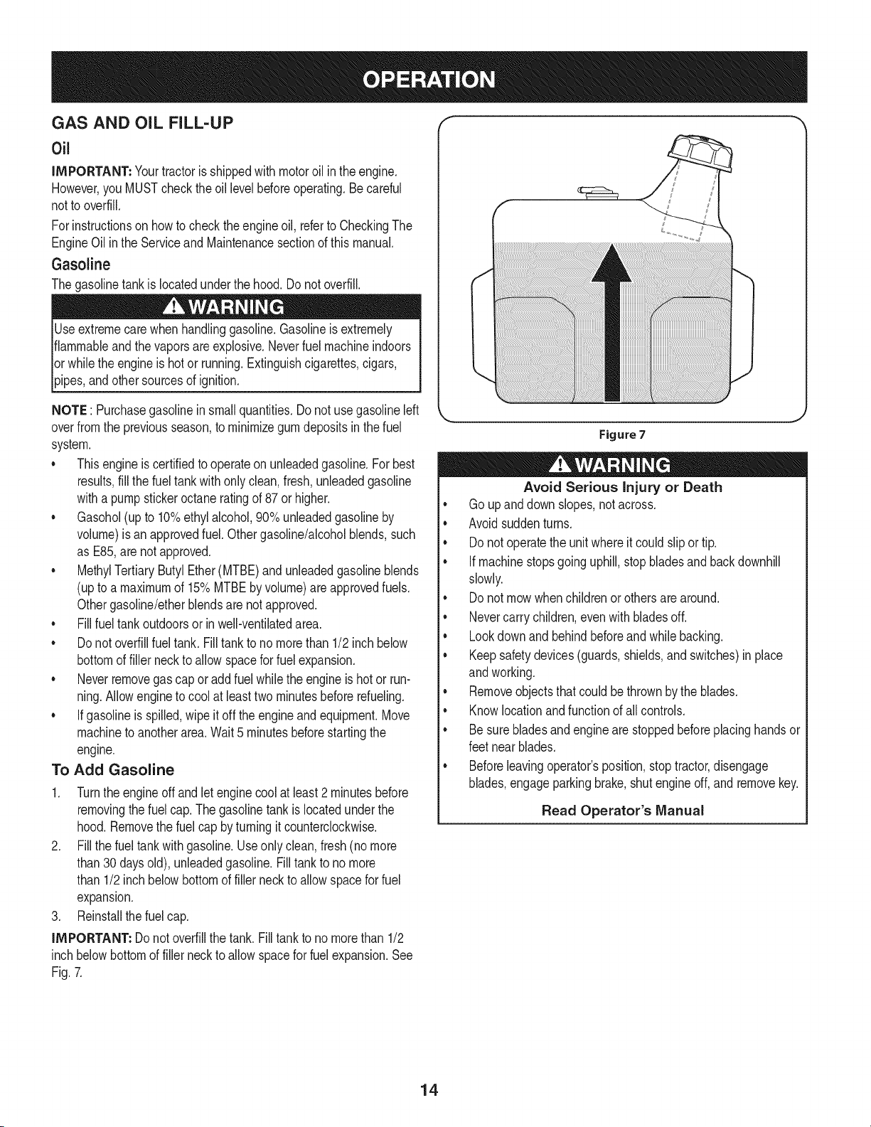
To Add Gasoline
1. Turnthe engineoff andlet enginecool at least2 minutesbefore
removingthe fuelcap. The gasolinetankis locatedunderthe
hood.Removethe fuel cap byturningit counterclockwise.
2. Fillthe fuel tankwith gasoline.Useonlyclean, fresh (no more
than30 daysold), unleadedgasoline.Filltank to no more
than 1/2inch belowbottomof filler neckto allowspacefor fuel
expansion.
3. Reinstallthe fuelcap.
IMPORTANT: Donot overfillthe tank.Fill tankto no morethan 1/2
inch belowbottomof filler neckto allowspacefor fuel expansion.See
Fig.7.
Figure7
Avoid Serious Injury or Death
• Go upanddownslopes,notacross.
• Avoidsuddenturns.
• Donot operatethe unitwhereit could slipor tip.
• If machinestopsgoing uphill,stop bladesand backdownhill
slowly.
• Donot mowwhenchildrenorothersare around.
• Nevercarrychildren,evenwith bladesoff.
• Lookdownand behindbeforeand whilebacking.
• Keepsafetydevices(guards,shields,and switches)in place
andworking.
• Removeobjectsthat couldbethrownby the blades.
• Knowlocationand functionof all controls.
• Be surebladesand engine are stoppedbeforeplacinghandsor
feetnear blades.
• Beforeleavingoperator'sposition,stop tractor,disengage
blades,engageparkingbrake,shutengineoff, and removekey.
Read Operator's Manual
14
SAFETY iNTERLOCK SYSTEM
Thesafetyinterlocksystemisdesignedfor safeoperationof thetrac-
tor.Ifthis systemshouldever malfunction,do not operatethe tractor.
Immediatelycontact1-800-4-MY-HOMEto havethe systemserviced.
• Thesafetyinterlocksystempreventsthe enginefromstarting
unlessthe parkingbrakeis engagedandthe PTO(BladeEngage)
leveris in thedisengaged(OFF)position.
• Thesafetyinterlocksystemwill automaticallyshutoff the engineif
the operatorleavesthe seatbeforeengagingthe parkingbrake.
• Thesafetyinterlocksystemwill automaticallyshut off the engine
ifthe operatorleavesthe tractor'sseatwiththe PTO(Blade
Engage)leverengaged,regardlessof whetherthe parkingbrake
is engaged.
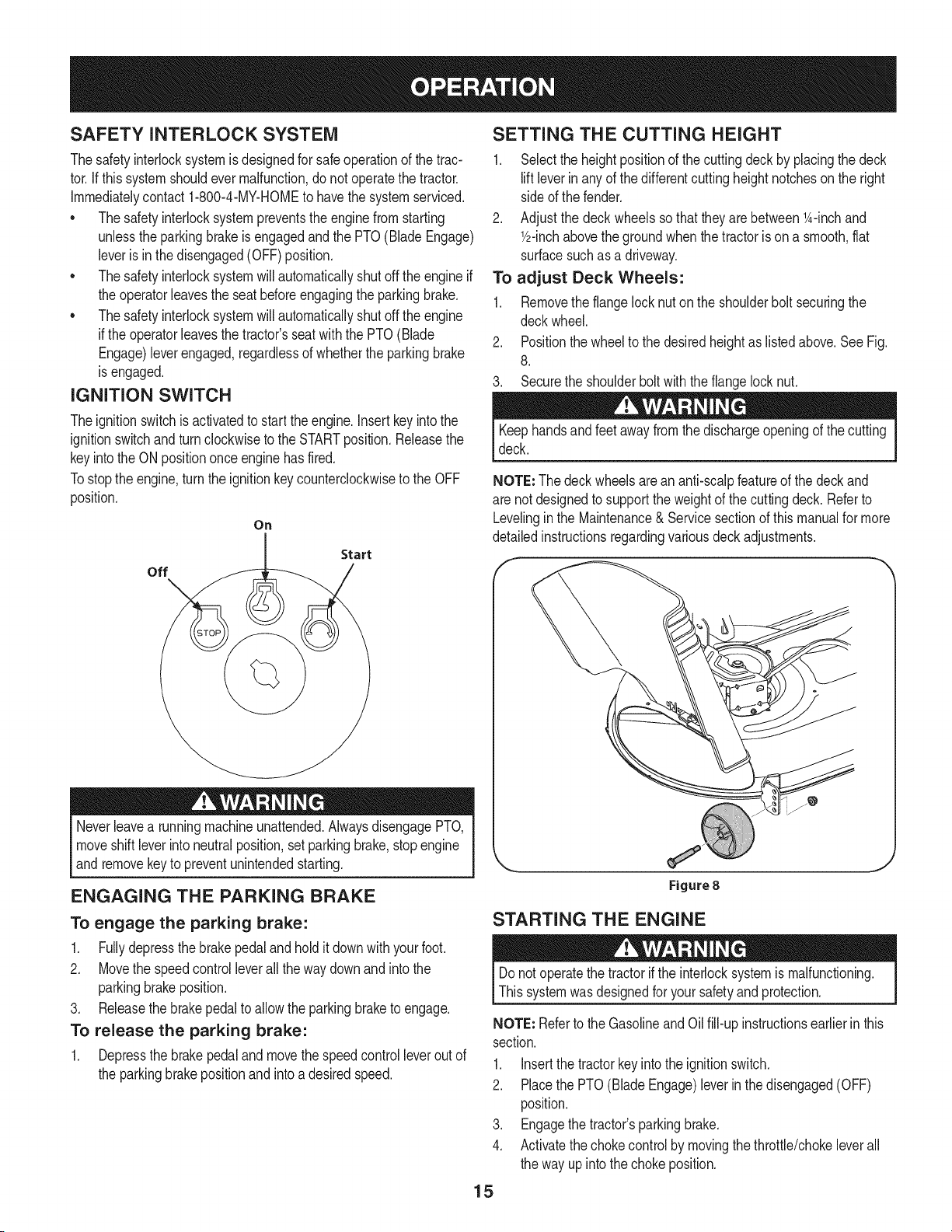
IGNITION SWITCH
Theignitionswitchis activatedto startthe engine,insert key intothe
ignitionswitchand turnclockwiseto the STARTposition.Releasethe
keyintothe ON positiononce enginehas fired.
Tostopthe engine,turnthe ignitionkey counterclockwiseto the OFF
position.
On
Start
off
Neverleavea runningmachineunattended.AlwaysdisengagePTO,
moveshift leverintoneutralposition,set parkingbrake,stop engine
andremovekeyto preventunintendedstarting.
ENGAGING THE PARKING BRAKE
To engage the parking brake:
1. Fullydepressthe brakepedaland hold it downwithyour foot.
2. Movethe speedcontrolleverall the waydownand intothe
parkingbrakeposition.
3. Releasethe brakepedalto allow theparkingbraketo engage.
To release the parking brake:
1. Depressthe brakepedalandmovethe speedcontrolleverout of
the parkingbrakepositionand intoa desiredspeed.
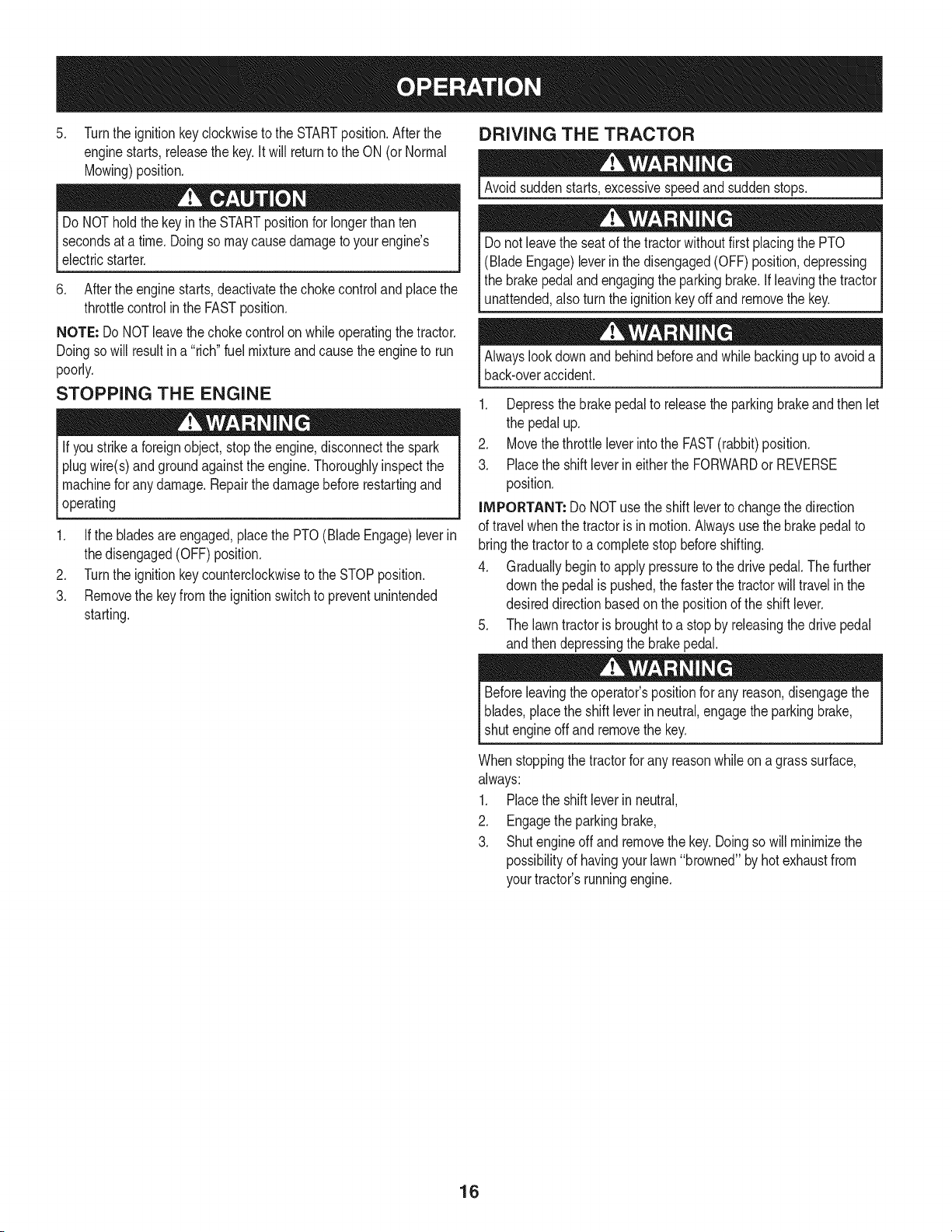
SETTING THE CUTTING HEIGHT
1. Selectthe heightpositionof the cuttingdeckby placingthe deck
liftleverinanyof the differentcuttingheightnotcheson the right
sideof the fender.
2. Adjustthe deck wheelssothattheyarebetween1A-inchand
Y2-inchabovethe groundwhenthe tractoris on a smooth,fiat
surfacesuchas a driveway.
To adjust Deck Wheels:
1. Removethe flangelock nuton the shoulderbolt securingthe
deckwheel.
2. Positionthe wheelto thedesiredheightas listedabove.See Fig.
8.
3. Securethe shoulderboltwith the flangelocknut.
Keephandsand feet away fromthe dischargeopeningof the cutting
deck.
NOTE: Thedeck wheelsare an anti-scalpfeatureof the deck and
are notdesignedto supportthe weightof the cuttingdeck. Referto
Levelinginthe Maintenance& Servicesectionof this manualfor more
detailedinstructionsregardingvariousdeckadjustments.
Figure8
STARTING THE ENGINE
Donot operatethe tractorif the interlocksystemis malfunctioning.
Thissystemwasdesignedfor yoursafetyand protection.
NOTE: Referto the Gasolineand Oil fill-up instructionsearlierin this
section.
1. Insertthe tractorkeyintothe ignitionswitch.
2. Placethe PTO(BladeEngage)leverin thedisengaged(OFF)
position.
3. Engagethe tractor'sparkingbrake.
4. Activatethechokecontrolby movingthethrottle/chokeleverall
the way up intothechoke position.
15
5. Turnthe ignitionkeyclockwiseto the STARTposition.Afterthe
enginestarts,releasethe key.It will returnto the ON (orNormal
Mowing)position.
Do NOThold the keyin the STARTpositionfor longerthanten
secondsat a time.Doingso maycausedamageto yourengine's
electricstarter.
6. Afterthe enginestarts,deactivatethe chokecontroland placethe
throttlecontrolinthe FASTposition.
NOTE: Do NOTleavethechokecontrol on whileoperatingthe tractor.
Doingso will resultina "rich" fuel mixtureand causethe engineto run
poorly.
STOPPING THE ENGINE
If youstrikea foreignobject,stopthe engine,disconnectthe spark
plugwire(s)andgroundagainstthe engine.Thoroughlyinspectthe
machinefor anydamage.Repairthe damagebeforerestartingand
operating
1. Ifthe bladesare engaged,placethe PTO(BladeEngage)leverin
thedisengaged(OFF) position.
2. Turnthe ignitionkeycounterclockwiseto the STOPposition.
3. Removethe keyfromthe ignitionswitchto preventunintended
starting.
DRIVING THE TRACTOR
Avoidsuddenstarts,excessivespeedand suddenstops.
Donot leavethe seatof the tractorwithoutfirst placingthe PTO
(BladeEngage)leverin the disengaged(OFF)position,depressing
the brakepedaland engagingthe parkingbrake.If leavingthe tractor
unattended,also turnthe ignitionkeyoff andremovethe key.
Alwayslook downand behindbeforeand while backingupto avoida
back-overaccident.
1. Depressthe brakepedalto releasethe parkingbrakeandthen let
the pedal up.
2. Movethethrottleleverintothe FAST(rabbit)position.
3. Placethe shift leverin eitherthe FORWARDor REVERSE
position.
IMPORTANT: Do NOTuse the shiftleverto changethedirection
of travel whenthe tractoris in motion.Alwaysusethe brakepedalto
bringthe tractorto acompletestopbeforeshifting.
4. Graduallybeginto applypressureto the drivepedal.Thefurther
downthe pedal is pushed,thefasterthe tractorwilltravel in the
desireddirectionbasedon the positionof the shift lever.
5. The lawntractoris broughtto a stopby releasingthedrive pedal
andthen depressingthe brakepedal.
Beforeleavingthe operator'spositionfor any reason,disengagethe
blades,placethe shift leverinneutral,engagethe parkingbrake,
shutengineoff and removethe key.
Whenstoppingthetractorfor any reasonwhileon agrasssurface,
always:
1. Placethe shift leverin neutral,
2. Engagethe parkingbrake,
3. Shutengineoff and removethe key.Doingso will minimizethe
possibilityof havingyour lawn"browned"byhot exhaustfrom
yourtractor'srunningengine.
16
DRiViNG ON SLOPES
Referto the SLOPEGAUGEinthe SafetyInstructionssectionof the
manualto helpdetermineslopeswhereyou mayoperatethis tractor
safely.
Do notmow on inclineswitha slopein excessof 15degrees(a rise
of approximately2-1/2feetevery 10feet). Thetractorcouldoverturn
andcauseseriousinjury.
• Mow up and downslopes,NEVERacross.
Exerciseextremecautionwhenchangingdirectionon slopes.
Watchfor holes, ruts,bumps,rocks,or otherhiddenobjects.
Uneventerraincouldoverturnthemachine.Tallgrasscan hide
obstacles.
Avoidturnswhendrivingona slope.If a turn mustbemade,turn
downthe slope.Turningup a slopegreatlyincreasesthechance
of a roll over.
Avoidstoppingwhendrivingupa slope.Ifit is necessaryto stop
whiledrivingupa slope,start up smoothlyand carefullyto reduce
the possibilityof flippingthe tractoroverbackward.
ENGAGING THE BLADES
Engagingthe PTO(Blade Engage)transferspowerto the cuttingdeck
orother (separatelyavailable)attachments.Toengagethe blades,
proceedas follows:
1. Movethe throttle/chokecontrol leverto the FAST(rabbit)position.
2. Graspthe PTO(BladeEngage)leverand pivotit all the way
forwardintothe engaged(ON)position.
3. Keepthe throttleleverin the FAST(rabbit)positionforthe most
efficientuseof thecuttingdeckor other(separatelyavailable)
attachments.
NOTE: The enginewill automaticallyshutoff if the PTOis engaged
withthe shiftleverin positionfor reversetravelwiththe ignitionkey in
the ONposition.
MULCHING
A mulchkit is availableasan attachment.Mulchingis a processof
recirculatinggrassclippingsrepeatedlybeneaththe cuttingdeck.The
ultra-fineclippingsarethenforcedback intothe lawnwheretheyact as
a naturalfertilizer.
A mulchkit canbe purchasedthroughthe retaillocationin which you
purchasedthistractor.For more information, simply contact Sears
at 1-800-4-MY-HOME®.
USING THE DECK LIFT LEVER
Toraisethe cuttingdeck,movethe decklift levertothe left,then place
it in the notchbestsuitedfor yourapplication.Referto SettingThe
CuttingHeightearlierinthis section.
MOWING
Tohelpavoidbladecontactor a thrownobject injury,keepbystand-
ers,helpers,childrenand pets at least75 feet from the machine
while it is in operation.Stopmachineif anyoneentersthe area.
The followinginformationwill be helpfulwhenusingthe cuttingdeck
withyourtractor:
Planyourmowingpatternto avoiddischargeof materialstoward
roads,sidewalks,bystandersandthe like. Also,avoiddischarging
materialagainstawall or obstructionwhichmaycausedischarged
materialto ricochetback towardthe operator.
Donot mowat highground speed,especiallyif a mulchkit or
grasscollectoris installed.
• Forbest resultsit is recommendedthat the first two laps becut
withthe dischargethrowntowardsthe center.Afterthe firsttwo
laps,reversethedirectionto throwthe dischargeto theoutside
for the balanceof cutting.This will givea betterappearanceto the
lawn.
• Donot cutthe grasstoo short. Shortgrassinvitesweedgrowth
andyellowsquicklyin dry weather.
• Mowingshouldalwaysbe done with the engineat full throttle.
• Underheavierconditionsit maybe necessaryto go backoverthe
cut areaa secondtimeto get a cleancut.
• Do NOTattemptto mowheavybrushandweedsandextremely
tall grass.Yourtractoris designedto mow lawns,NOTclear
brush.
• Keepthe bladessharpand replacethe bladeswhenworn. Refer
to CuttingBladesin the Servicesectionof this manualfor proper
bladesharpeninginstructions.
HEADLIGHTS
• The lampsare ONwheneverthe tractor'sengineis running.
• The lampsturn OFFwhenthe ignitionkeyis movedto the STOP
position.
17
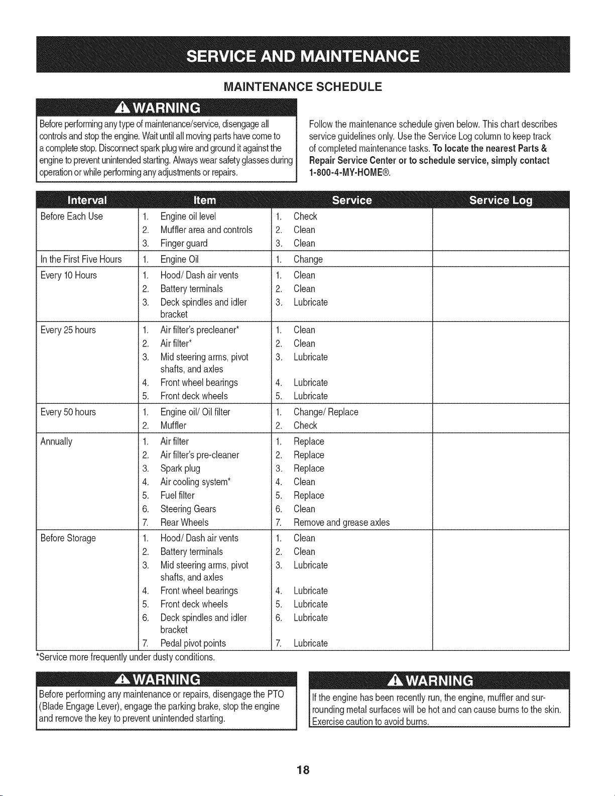
MAINTENANCE SCHEDULE
Beforeperforminganytypeof maintenance/service,disengageall
controlsandstoptheengine.Waituntilall movingpartshavecometo
acompletestop.Disconnectsparkplugwireandgrounditagainstthe
enginetopreventunintendedstarting.Alwayswearsafetyglassesduring
operationor whileperforminganyadjustmentsor repairs.
Followthe maintenanceschedulegivenbelow.Thischart describes
serviceguidelinesonly.Usethe ServiceLog columnto keeptrack
of completedmaintenancetasks.To locate the nearest Parts &
Repair Service Centeror to scheduleservice,simplycontact
1-800-4-MY-HOME®.
BeforeEachUse
In the FirstFiveHours
Every10Hours
Every25 hours
Every50 hours
Annually
BeforeStorage
1. Engineoil level
2. Mufflerarea and controls
3. Fingerguard
1. EngineOil
1. Hood/Dashair vents
2. Batteryterminals
3. Deckspindlesand idler
bracket
1. Air filter'sprecleaner*
2. Air filter*
3. Midsteeringarms,pivot
shafts,and axles
4. Frontwheelbearings
5. Frontdeckwheels
1. Engineoil/Oil filter
2. Muffler
1. Air filter
2. Air filter'spre-cleaner
3. Sparkplug
4. Air coolingsystem*
5. Fuelfilter
6. SteeringGears
7. RearWheels
1. Hood/Dashair vents
2. Batteryterminals
3. Midsteeringarms,pivot
shafts,and axles
4. Frontwheelbearings
5. Frontdeckwheels
6. Deckspindlesand idler
bracket
7. Pedalpivotpoints
1. Check
2. Clean
3. Clean
1. Change
1. Clean
2. Clean
3. Lubricate
1. Clean
2. Clean
3. Lubricate
4. Lubricate
5. Lubricate
1. Change/Replace
2. Check
1. Replace
2. Replace
3. Replace
4. Clean
5. Replace
6. Clean
7. Removeand greaseaxles
1. Clean
2. Clean
3. Lubricate
4. Lubricate
5. Lubricate
6. Lubricate
7. Lubricate
*Servicemorefrequentlyunderdustyconditions.
Beforeperformingany maintenanceor repairs,disengagethe PTO
(BladeEngageLever),engagethe parkingbrake,stopthe engine
and removethe key to preventunintendedstarting.
Ifthe enginehasbeen recentlyrun,the engine,mufflerand sur-
roundingmetalsurfaceswill be hotand cancause burnsto the skin.
Exercisecautionto avoidburns.
18
ENGINE MAINTENANCE
Checking the Engine Oil
Onlyuse high qualitydetergentoil ratedwith APIserviceclassification
SF,SG,SH,or SJ, Selectthe oil's SAEviscositygradeaccordingto
the expectedoperatingtemperature.Followthe chartbelow.
Althoughmulti-viscosityoils (5W20,10W30,etc.)improvestarting
in coldweather,theywill result in increasedoil consumptionwhen
usedabove32°E Checkyour engineoil levelmorefrequentlyto avoid
possibleenginedamagefrom runninglowon oil.
('_older _ 32°F _War me'_r
Oil Viscosity Chart
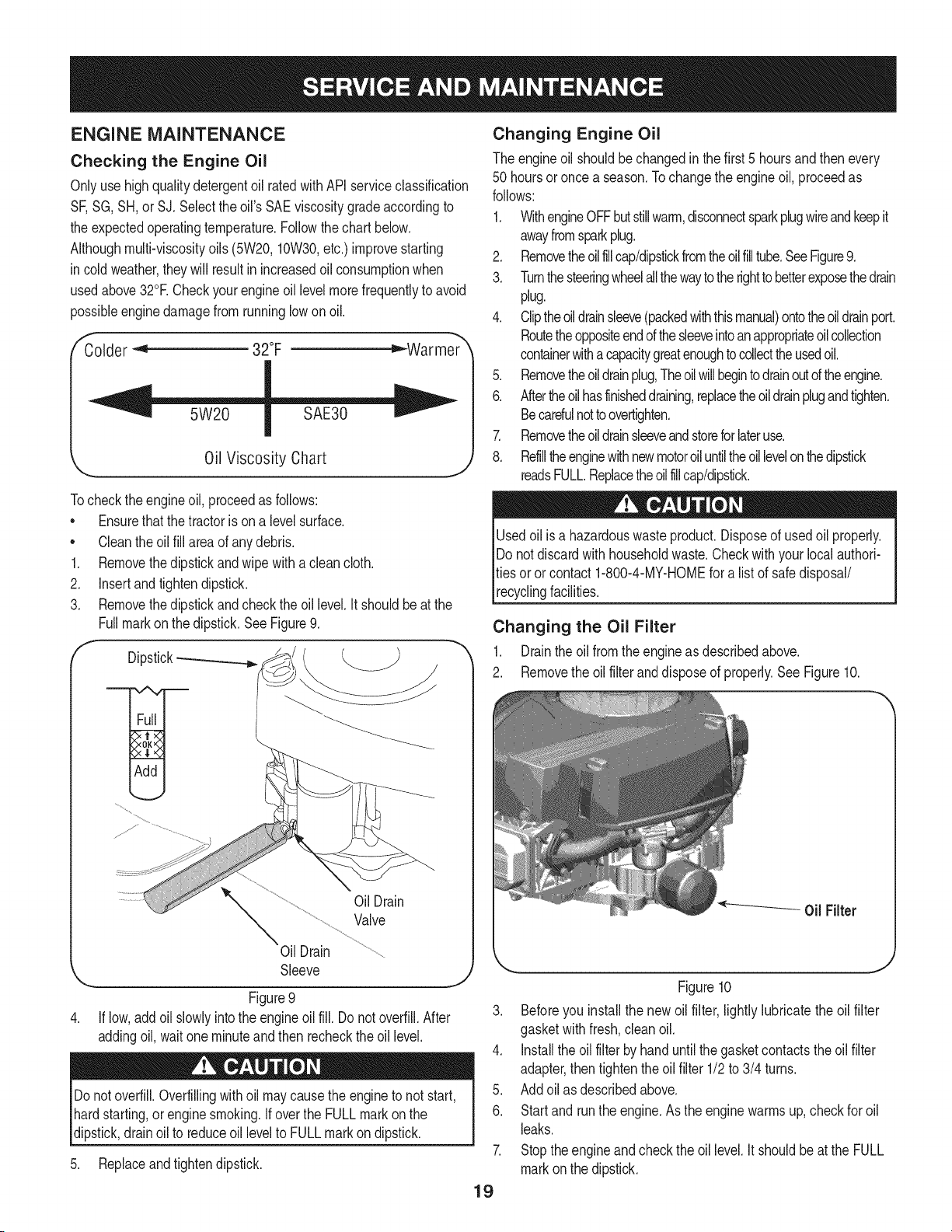
Tocheckthe engineoil, proceedas follows:
• Ensurethatthe tractoris ona levelsurface.
• Cleantheoil fill areaof anydebris.
1. Removethedipstickandwipe withaclean cloth.
2. Insertandtightendipstick.
3. Removethedipstickand checkthe oil level.It shouldbeat the
Fullmarkonthe dipstick.See Figure9.
f
Dipstick-_
OilDrain
Valve
Oil Drain
Sleeve
J
Figure9
If low,addoil slowlyintothe engineoil fill. Do notoverfill.After
addingoil, wait one minuteand then recheckthe oil level.
Donotoverfill.Overfillingwithoil maycausethe engine to not start,
hardstarting,or engine smoking.If overthe FULLmarkonthe
dipstick,drainoil to reduceoil levelto FULLmarkondipstick.
5. Replaceandtightendipstick.
Changing Engine Oil
The engineoil shouldbe changedin the first 5 hoursand thenevery
50 hoursoronce a season.Tochangethe engineoil, proceedas
follows:
1. WithengineOFFbutstillwarm,disconnectsparkplugwireandkeepit
awayfromsparkplug.
2. Removetheoilfillcap/dipstickfromtheoilfilltube.SeeFigure9.
3. Turnthesteeringwheelallthewaytothe righttobetterexposethedrain
plug.
4. Cliptheoildrainsleeve(packedwiththismanual)ontotheoildrainport.
Routetheoppositeendofthesleeveintoanappropriateoilcollection
containerwithacapacitygreatenoughtocollecttheusedoil.
5. Removetheoildrainplug,Theoil willbegintodrainoutoftheengine.
6. Aftertheoilhasfinisheddraining,replacetheoildrainplugandtighten.
Becarefulnottoovertighten.
7. Removetheoildrainsleeveandstoreforlateruse.
8. Refilltheenginewithnewmotoroiluntiltheoil levelonthedipstick
readsFULL.Replacetheoilfillcap/dipstick.
Usedoil is a hazardouswasteproduct.Disposeof usedoil properly.
Do notdiscardwith householdwaste.Checkwith your localauthori-
ties oror contact1-800-4-MY-HOMEfor a list of safedisposal/
recyclingfacilities.
Changing the Oil Filter
1. Drainthe oil fromthe engineas describedabove.
2. Removethe oil filter anddisposeof properly.See Figure10.
Figure10
3. Beforeyou install the newoil filter, lightly lubricate the oil filter
gasketwithfresh,cleanoil.
4. Installthe oil filterbyhanduntilthe gasketcontactstheoil filter
adapter,then tightenthe oilfilter 1/2to 3/4 turns.
5. Addoil as describedabove.
6. Startand runthe engine.Asthe enginewarmsup,checkfor oil
leaks.
7. Stoptheengineandcheckthe oil level.It shouldbeat the FULL
markonthe dipstick.
19
Fuel Filter Air Cleaner
Gasolineand itsvaporsareextremelyflammableandexplosive.Fire
orexplosioncan causesevereburnsor death.
• Keepgasolineawayfromsparks,openflames,pilotlights,heat,
andotherignitionsources.
• Checkfuel lines,tank,cap, and fittingsfrequentlyforcracks or
leaks.Replaceif necessary.
• Beforereplacingthe fuelfilter,drainthe fueltankas per the
instructionsbelow.
• Do notdrainfuel whenthe engine ishot. Allowthe engine
adequatetimeto cool. Drainfuel intoan approvedcontainer
outdoors,awayfromopenflame.
• Drainanylargevolumeof fuelfromthe tankby disconnectingthe
fuel linefrom the in-linefuelfilterneartheengine.
• Removethe fuel line from the In-lineside (sidetowardsthe fuel
tank)of thefuel filter.
• Replacementpartsmustbethe sameand installedin the same
positionas theoriginal parts.
• Iffuel spills,waituntil itevaporatesbeforestartingengine.
• Beforereplacingthe fuelfilter,drainthe fueltank. Otherwisefuel
can leakout andcausea fireor explosion.
To Drainthe fuel:
1. Locatethefuelfilter,whichis routedon the leftsideofthe engine
betweenthe fueltankand the carburetor,and maybe attachedto
theenginewitha tie strap.Cutthetie strap,ifpresent,then pinch
thein-lineclamponthefuelfilterwitha pairof pliers,slidethe
clampupthefuelline.Pullthe fuellinefreefrom thefilterand place
theopenendof the lineintoanapprovedcontainerto drainthefuel.
Tochangethe fuel filter:
1. Usepliersto squeezethe tabson the otherclamp(theout-line
sideof the fuel filter),thenslidethe clampawayfromthe fuel filter.
Twistandpull the fuellineoff of the fuelfilter.SeeFigure11.
Clamp
Fuel
Line
Tab
Figure11
.J
2. Checkthe fuel linesfor cracksor leaks.Replaceif necessary.
3. Replacethe fuel filter withan originalequipmentreplacement
filter.Call1-800-4-MY-HOME®to purchasethe originalequip-
mentreplacementfilter.
4. Securethe fuel lineswiththe clamps.
Iffilters,or coversare notinstalledcorrectlyseriousinjuryordeath
could resultfrom backfire.Do notattemptto startthe enginewith
themremoved.
Donot use pressurizedair or solventsto cleanthe air cleaner
cartridge.
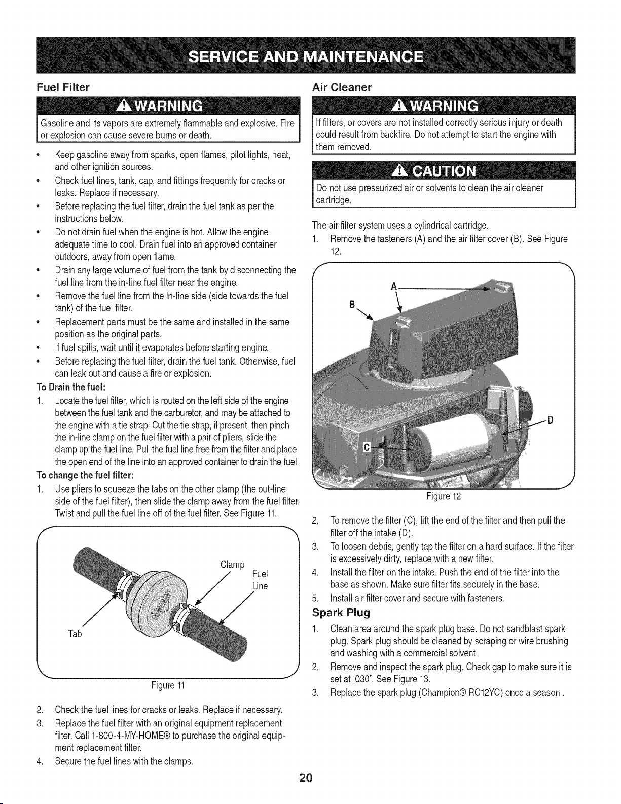
The air filter systemuses a cylindricalcartridge.
1. Removethe fasteners(A) and the airfiltercover(B). See Figure
12.
A
Figure12
2. To removethe filter(C),liftthe end of the filterand then pullthe
filteroff the intake(D).
3. To loosendebris,gentlytapthe filteron a hardsurface,if thefilter
is excessivelydirty,replacewith a newfilter.
4. installthe filteronthe intake.Pushthe endof the filterintothe
baseas shown.Makesurefilter fits securelyin the base.
5. installair filter cover and securewith fasteners.
Spark Plug
1. Cleanareaaroundthe sparkplugbase.Donot sandblastspark
plug. Sparkplugshouldbe cleanedby scrapingor wirebrushing
andwashingwith a commercialsolvent
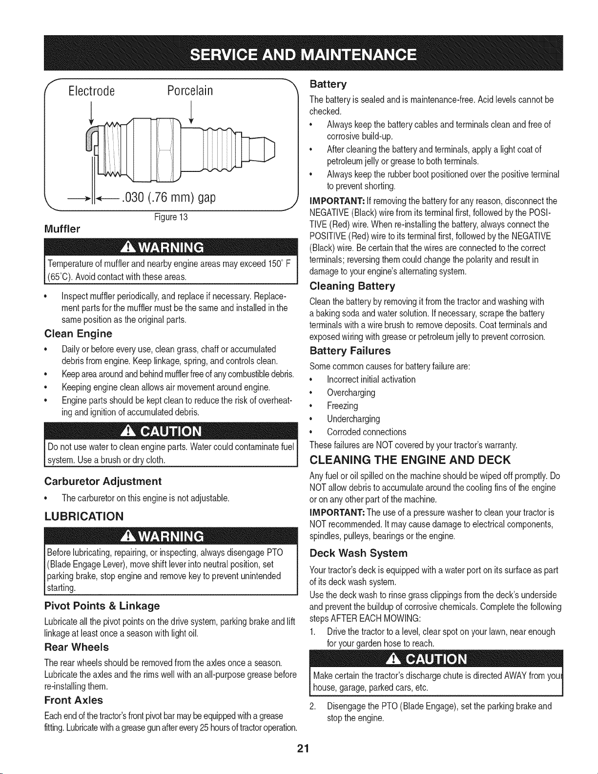
2. Removeandinspectthe sparkplug.Checkgap to makesureitis
setat .030".SeeFigure13.
3. Replacethe sparkplug(Champion®RC12YC)oncea season.
2O
f
Electrode Porcelain
J
Temperatureof mufflerandnearbyengineareasmayexceed150° F
(65°0).Avoidcontactwith these areas.
• inspectmufflerperiodically,and replaceif necessary.Replace-
mentpartsfor the mufflermustbethe sameand installedin the
samepositionas the originalparts.
Clean Engine
• Dailyor beforeeveryuse,cleangrass,chaff or accumulated
debrisfromengine.Keeplinkage,spring,andcontrolsclean.
• Keepareaaroundandbehindmufflerfreeofanycombustibledebris.
• Keepingenginecleanallowsair movementaroundengine.
• Enginepartsshouldbe keptcleanto reducethe risk of overheat-
ingandignitionof accumulateddebris.
Do notuse waterto cleanengineparts.Watercouldcontaminatefuel
system.Usea brushordry cloth.
Carburetor Adjustment
• Thecarburetoron thisengineis not adjustable.
LUBRICATION
Beforelubricating,repairing,or inspecting,alwaysdisengagePTO
(BladeEngageLever),moveshift leverinto neutralposition,set
parkingbrake,stopengineand removekeyto preventunintended
starting.
Pivot Points & Linkage
Lubricateall the pivotpointson thedrive system,parkingbrakeand lift
linkageat leastoncea seasonwith lightoil.
Rear Wheels
Battery
The batteryis sealedandis maintenance-free.Acidlevelscannotbe
checked.
• Alwayskeepthe batterycablesandterminalscleanand free of
corrosivebuild-up.
• Aftercleaningthe batteryand terminals,applya lightcoatof
petroleumjelly or greaseto bothterminals.
• Alwayskeepthe rubberbootpositionedoverthe positiveterminal
to preventshorting.
IMPORTANT: if removingthe batteryfor any reason,disconnectthe
NEGATIVE(Black)wirefromitsterminalfirst,followedby the POSI-
TIVE(Red)wire.When re-installingthe battery,alwaysconnectthe
POSITIVE(Red)wire to its terminalfirst, followedbythe NEGATIVE
(Black)wire.Becertainthat the wiresareconnectedto the correct
terminals;reversingthemcouldchangethe polarityand result in
damageto yourengine'salternatingsystem.
Cleaning Battery
Cleanthe batteryby removingit from the tractorandwashingwith
a bakingsodaandwatersolution.If necessary,scrapethe battery
terminalswitha wirebrushto removedeposits.Coatterminalsand
exposedwiringwithgreaseor petroleumjelly to preventcorrosion.
Battery Failures
Somecommoncausesfor batteryfailureare:
• incorrectinitialactivation
• Overcharging
• Freezing
• Undercharging
• Corrodedconnections
Thesefailuresare NOTcoveredbyyourtractor'swarranty.
CLEANING THE ENGINE AND DECK
Any fuelor oil spilledon the machineshouldbewipedoff promptly.Do
NOTallowdebristo accumulatearoundthe coolingfinsof the engine
or onany otherpartof the machine.
IMPORTANT: The useof a pressurewasherto cleanyourtractoris
NOTrecommended.Itmaycausedamageto electricalcomponents,
spindles,pulleys,bearingsor the engine.
Deck Wash System
Yourtractor'sdeckis equippedwith a water porton its surfaceas part
of itsdeck wash system.
Usethe deck washto rinsegrassclippingsfromthe deck'sunderside
and preventthe buildupof corrosivechemicals.Completethe following
stepsAFTEREACHMOWING:
1. Drivethe tractorto a level,clear spoton yourlawn, nearenough
for yourgarden hoseto reach.
The rearwheelsshouldbe removedfrom the axlesoncea season.
Lubricatethe axles and the rimswell with an all-purposegreasebefore
re-installingthem.
Front Axles
Eachendof thetractor'sfrontpivotbarmaybeequippedwithagrease
fitting.Lubricatewithagreasegunafterevery25 hoursoftractoroperation.
Makecertainthe tractor'sdischargechute is directedAWAYfromyoul
house,garage,parkedcars,etc.
2. Disengagethe PTO(BladeEngage),setthe parkingbrakeand
stopthe engine.
21
3. Threadthe hosecoupler(packagedwithyourtractor'sOperator's
Manual)ontothe end of your gardenhose.
4. Attachthe hosecouplerto the waterport onyourdeck'ssurface.
SeeFigure14.
J
j,
/
f
J _; .......... ........
8
Figure14
5. Turnthe wateron.
6. Whilesittinginthe operator'spositiononthe tractor,startthe
engineandplacethe throttleleverinthe FAST(rabbit)position.
7. Movethe tractor'sPTO(BladeEngage)intothe ON position.
8. Remaininthe operator'spositionwiththecuttingdeckengaged
for a minimumof two minutes,allowingthe undersideof the
cuttingdeckto thoroughlyrinse.
9. Movethe tractor'sPTO(BladeEngage)intothe OFFposition.
10. Turnthe ignitionkeytothe STOPpositionto turnthe tractor's
engineoff.
11. Turnthe wateroff anddetachthe hosecouplerfromthe water
port on yourdeck'ssurface.
12. Repeatsteps4through11on the oppositeside of the cutting
deck.
Aftercleaningyourdeck, returnto the operator'spositionand engage
the PTO.Keepthe cuttingdeckrunningfor a minimumof twominutes,
allowingthe undersideof thecuttingdeck to thoroughlydry.
ADJUSTMENTS
Neverattemptto makeanyadjustmentswhilethe engineis running,
exceptwherespecifiedin the operator'smanual.
Leveling the Deck
NOTE: Checkthe tractor'stire pressurebeforeperforminganydeck
levelingadjustments.Referto Tires in the Servicesectionof this
manualfor moreinformationregardingtire pressure.
Front To Rear
Thefrontof the cuttingdeckis supportedby a stabilizerbar that can
beadjustedto levelthe deckfrom front to rear.Thefrontof the deck
shouldbe between_A-inchand 3A-inchlowerthanthe rearof the deck.
Adjustif necessaryas follows:
1. Withthe tractorparkedon a firm, levelsurface,placethe lever
for lifting the platformon the secondto the top notch(second
highestposition)and rotatethe bladeas closeas possibleto the
dischargechannelthat is parallelto the tractor.
2. Measurethedistancefromthe frontof the bladetip to the ground
andthe rearof the bladetip to theground.Thefirst measure-
menttakenshouldbe between_A"and3A"less thanthe second
measurement.Determinethe approximatedistancenecessaryfor
properadjustmentandproceed,if necessary,to the nextstep.
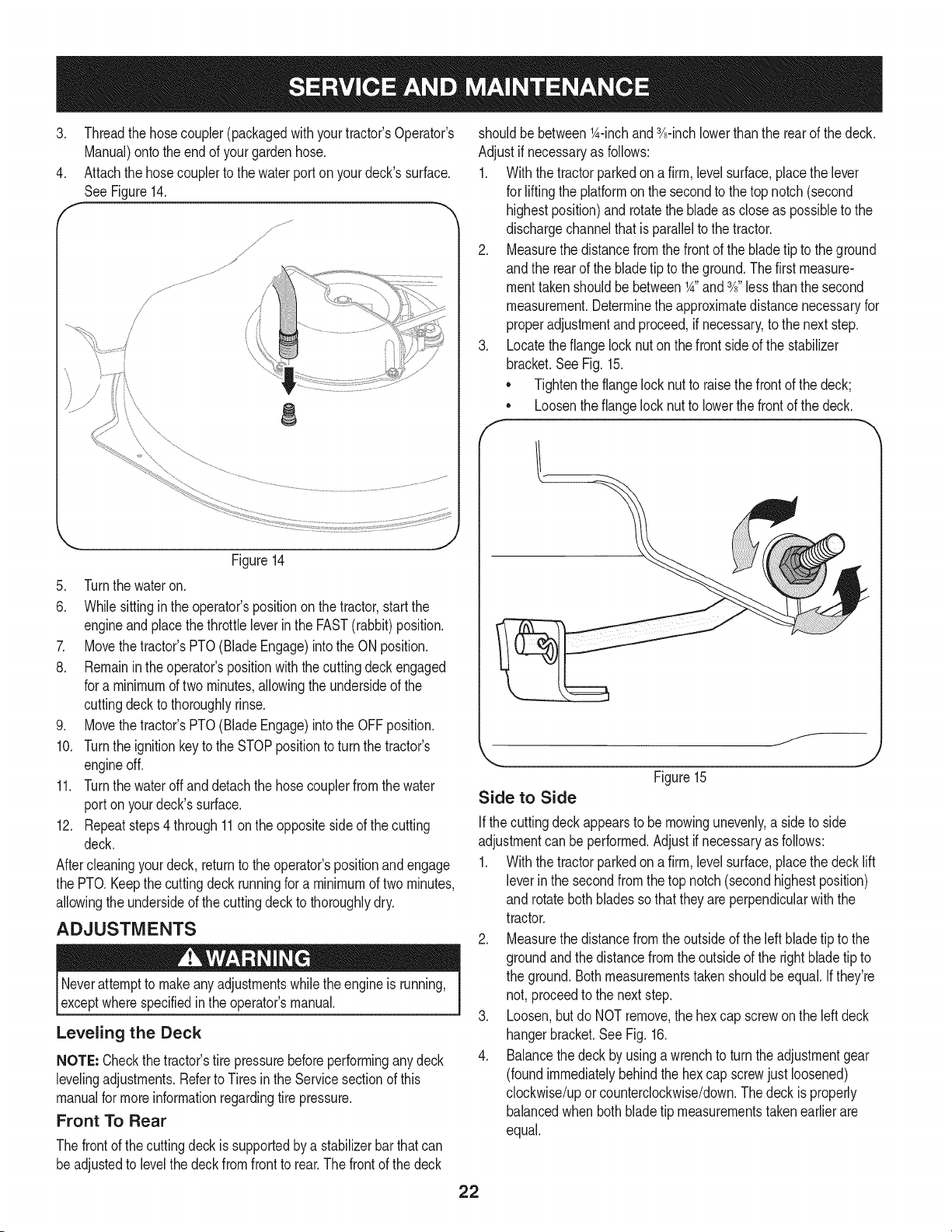
3. Locatethe flangelocknut on the frontsideof the stabilizer
bracket.SeeFig. 15.
• Tightenthe flangelock nut to raisethe frontof the deck;
Loosentheflangelock nutto lowerthe frontof thedeck.
o
f
f__
Side to Side
Figure15
J
Ifthe cuttingdeck appearsto be mowingunevenly,a sideto side
adjustmentcan be performed.Adjustif necessaryas follows:
1. Withthe tractorparkedon a firm, levelsurface,placethe deck lift
leverin the secondfromthe top notch (secondhighestposition)
and rotatebothbladessothat theyare perpendicularwiththe
tractor.
2. Measurethedistancefromthe outsideof the left bladetip to the
groundandthe distancefromthe outsideof the rightblade tip to
the ground.Bothmeasurementstakenshouldbe equal.If they're
not, proceedto the nextstep.
3. Loosen,but do NOTremove,the hexcap screwon the left deck
hangerbracket.SeeFig. 16.
4. Balancethedeck by usinga wrenchto turn theadjustmentgear
(foundimmediatelybehindthehex cap screwjust loosened)
clockwise/uporcounterclockwise/down.Thedeck is properly
balancedwhen bothbladetip measurementstakenearlierare
equal.
22
He× Cap Screw
'_._. j
Figure16
5. Retightenthe hexcap screwon the left deckhangerbracket
whenproperadjustmentis achieved.
Seat Adjustment
Referto the Assemblysectionof this manualfor seatadjustment
instructions.
Parking Brake Adjustment
Neverattemptto adjustthe brakeswhiletheengineis running.Always
disengagePTO(bladeengage)lever,moveshiftleverintoneutral
position,stopengineandremovekeyto preventunintendedstarting.
If thetractordoes notcome to acompletestop whenthe brakepedal
is completelydepressed,or if the tractor'srearwheelscan rollwiththe
parkingbrakeapplied,the brakeis in needof adjustment.Contactthe
nearest Sears Service Center to haveyourbrakesproperlyadjusted.
Tolocatethe nearest Parts& Repair ServiceCenter or to schedule
service,contact 1-800-4-MY-HOME®.
CUTTING DECK REMOVAL
To remove the cutting deck, proceed as follows:
1. Placethe PTO(Blade Engage)leverin the disengaged(OFF)
positionand engagethe parkingbrake.
2. Lowerthe deck by movingthe deck lift lever intothe bottom
notchon the rightfender.
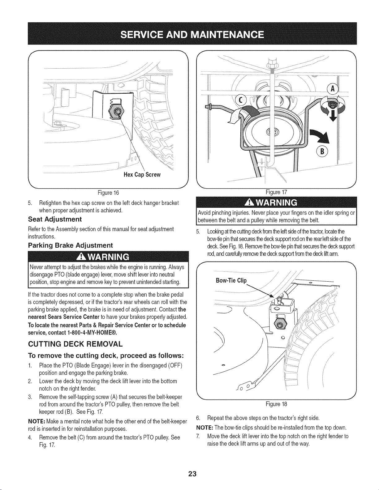
3. Removetheself-tappingscrew(A) that securesthe belt-keeper
rodfromaroundthe tractor'sPTOpulley,thenremovethe belt
keeperrod(B). See Fig. 17.
NOTE: Makea mentalnotewhatholethe otherendof the belt-keeper
rodisinsertedinfor reinstallationpurposes.
4. Removethebelt (C) from aroundthetractor'sPTOpulley.See
Fig.17.
Figure17
Avoidpinchinginjuries.Neverplaceyourfingerson the idler springor
betweenthe beltand a pulleywhileremovingthe belt.
Lookingatthecuttingdeckfromtheleftsideofthetractor,locatethe
bow-tiepinthatsecuresthedecksupportrodontherearIdtsided the
deck.SeeFig.18.Removethebow-tiepinthatsecuresthedecksupport
rod,andcarefullyremovethedecksupportfromthedeckliftarm.
Figure18
6. Repeatthe abovestepson the tractor'srightside.
NOTE: The bow-tieclipsshouldbe re-installedfromthe top down.
7. Movethe decklift leverintothe top notchon the rightfenderto
raisethe deck lift arms up and out of the way.
23
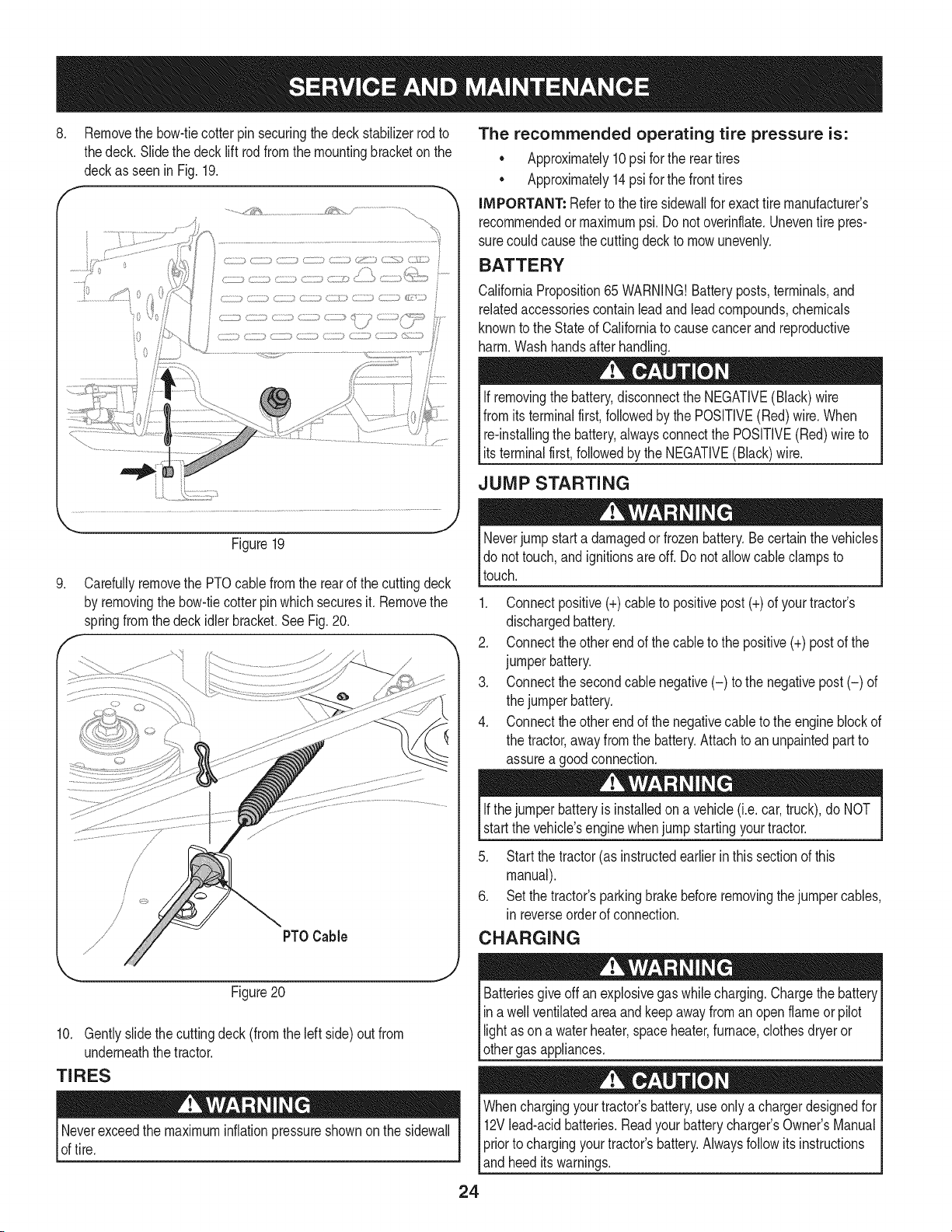
.
Removethe bow-tiecotterpin securingthe deckstabilizerrod to
thedeck. Slidethe decklift rodfrom the mountingbracketon the
deckas seenin Fig.19.
..........._'_¢& _ .......................................
Figure19
.
f
Carefullyremovethe PTOcablefrom the rearof the cuttingdeck
by removingthe bow-tiecotterpinwhichsecuresit. Removethe
springfromthe deck idler bracket.See Fig.20.
PTOCable
Figure20
10. Gentlyslidethe cuttingdeck(fromthe left side)out from
underneaththe tractor.
TIRES
Neverexceedthe maximuminflationpressureshownonthe sidewall
of tire.
The recommended operating tire pressure is:
• Approximately10psi for the reartires
• Approximately14psi for the fronttires
IMPORTANT: Referto the tire sidewallfor exacttire manufacturer's
recommendedormaximumpsi.Donot overinflate.Uneventire pres-
surecould causethe cuttingdeckto mowunevenly.
BATTERY
CaliforniaProposition65 WARNING!Batteryposts,terminals,and
relatedaccessoriescontainleadandlead compounds,chemicals
knownto the Stateof Californiato causecancerand reproductive
harm.Washhandsafter handling.
If removingthe battery,disconnectthe NEGATIVE(Black)wire
fromits terminalfirst,followedbythe POSITIVE(Red) wire.When
re-installingthe battery,alwaysconnectthe POSITIVE(Red)wire to
Its termna f rst,fo owedby the NEGATVE (Back) w re.
JUMP STARTING
Neverjump starta damagedor frozenbattery.Be certain thevehicles
do not touch,and ignitionsare off. Do notallowcable clampsto
touch.
1. Connectpositive(+)cableto positivepost (+)of yourtractor's
dischargedbattery.
2. Connecttheotherendof thecableto the positive(+)postof the
jumperbattery.
3. Connectthesecondcable negative(-) to the negativepost (-) of
the jumperbattery.
4. Connecttheotherendof thenegativecableto the engineblockof
the tractor,away fromthe battery.Attachto an unpaintedpartto
assurea goodconnection.
Ifthejumper batteryis installedon a vehicle (i.e.car, truck),do NOT
startthe vehicle'senginewhenjump startingyourtractor.
5. Startthe tractor(as instructedearlierin this sectionof this
manual).
6. Set the tractor'sparkingbrakebeforeremovingthejumpercables,
in reverseorderof connection.
CHARGING
give off an explosivegas whilecharging.Chargethe batteryI
Batteries
ina wellventilatedareaandkeepaway froman openflame or pilot
ght as ona waterheater,spaceheater,furnace,c othesdryeror |
othergas appliances.
J
Whenchargingyourtractor'sbattery,useonlya chargerdesignedfor I
12Vlead-acidbatteries.Readyourbatterychargers Owners Manual
priorto chargingyourtractors battery.Alwaysfollowits instructions I
land heed ts warnngs. j
24
If yourtractorhasnot been putinto usefor an extendedperiodof time,
chargethe batteryas follows:
1. Setyour batterychargerto delivera maxof 10amperes.
If yourbatterychargeris automatic,chargethe batteryuntilthe
chargerindicatesthat chargingis complete.Ifthe chargeris not
automatic,chargefor no fewerthaneight hours.
FUSE
One20 AMPfuse is installedin yourtractor'swiringharnessto protect
the tractor'selectricalsystemfromdamagecaused byexcessive
amperage.
If theelectricalsystemdoesnot function,or yourtractor'senginewill
not crank,first checkto be certainthat the fusehasnot blown.It can
befoundat the rear of the unit, underneaththefenderlocatedby the
battery.
Alwaysusea fusewiththe sameamperagecapacityfor replacement.
CUTTING BLADES
Shutthe engineoff and removeignitionkey beforeremovingthe
cuttingblade(s)for sharpeningor replacement.Protectyourhands
by usingheavygloveswhengraspingthe blade.
Periodicallyinspectthe bladeand/or spindlefor cracks or damage,
especiallyafter you'vestrucka foreignobject. Donot operatethe
machineuntil damagedcomponentsare replaced.
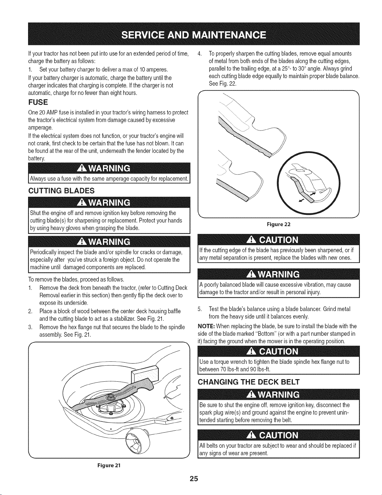
To properlysharpenthe cuttingblades,removeequalamounts
of metalfrombothendsof the bladesalongthe cuttingedges,
parallelto the trailingedge,at a 250.to 300angle.Alwaysgrind
eachcutting bladeedge equallyto maintainproperbladebalance.
SeeFig.22.
Figure 22
Ifthe cuttingedge of the bladehas previouslybeensharpened,or if
any metalseparationis present,replacethe bladeswith newones.
Toremovethe blades,proceedas follows.
1. Removethedeckfrom beneaththe tractor,(referto CuttingDeck
Removalearlierinthis section)thengentlyflip thedeck overto
exposeitsunderside.
2. Placea blockof woodbetweenthe centerdeckhousingbaffle
andthe cuttingbladeto act as a stabilizer.SeeFig.21.
3. Removethehex flangenutthat securesthe bladeto the spindle
assembly.SeeFig.21.
A poorlybalancedbladewill causeexcessivevibration,maycause
damageto the tractorand/or resultin personalinjury.
5. Testthe blade'sbalanceusinga blade balancer.Grind metal
from the heavyside untilit balancesevenly.
NOTE: Whenreplacingthe blade,be sureto installthe bladewith the
sideof the blademarked"Bottom"(orwitha part numberstampedin
it)facingthe groundwhenthe moweris in the operatingposition.
Figure 21
Usea torquewrenchto tightenthe bladespindlehexflangenut to
between70Ibs-ftand 90 Ibs-ft.
CHANGING THE DECK BELT
Besureto shut the engineoff, removeignitionkey,disconnectthe
Isparkplugwire(s)andgroundagainstthe engineto preventunin-
ltended startingbeforeremovingthe belt.
All beltsonyourtractoraresubjectto wearand shouldbe replacedif
any signsof wearare present.
25
IMPORTANT: The V-beltfoundon yourtractoris speciallydesigned
to engageand disengagesafely.A substitute(non-OEM)V-beltcan
bedangerousby notdisengagingcompletely.Fora properworking
machine,useidenticalequipmentbeltsas listedin the parts pagesof
thisOperator'sManual.
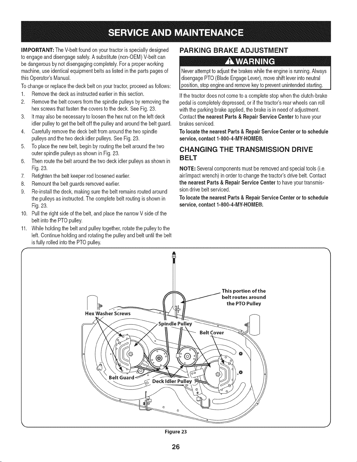
Tochangeor replacethe deck belt onyourtractor,proceedas follows:
1. Removethe deck as instructedearlierinthis section.
2. Removethe beltcoversfromthe spindlepulleysby removingthe
hexscrewsthatfastenthecoversto the deck.SeeFig.23.
3. It mayalso be necessaryto loosenthe hex nuton the leftdeck
idlerpulleyto getthe belt off the pulleyandaroundthe beltguard.
4. Carefullyremovethe deckbeltfromaroundthe two spindle
pulleysandthetwo deck idler pulleys,See Fig, 23,
5. Toplacethe newbelt, begin by routingthe belt aroundthe two
outerspindlepulleysas shownin Fig, 23,
6. Thenroutethe beltaroundthe twodeck idler pulleysas shownin
Fig.23,
7. Retightenthe belt keeperrodloosenedearlier.
8. Remountthebelt guardsremovedearlier,
9. Re-installthedeck, makingsurethe belt remainsroutedaround
the pulleysas instructed.Thecompletebelt routingis shownin
Fig,23.
10. Pullthe rightside ofthe belt,and placethe narrowVside of the
belt intothe PTOpulley.
11. Whileholdingthe beltandpulleytogether,rotatethepulleyto the
left. Continueholdingand rotatingthe pulleyand beltuntilthe belt
is fully rolled intothe PTOpulley.
PARKING BRAKE ADJUSTMENT
Neverattemptto adjustthe brakeswhiletheengineis running.Always
disengagePTO(BladeEngageLever),moveshiftleverintoneutral
position,stopengineandremovekeyto preventunintendedstarting.
Ifthe tractordoesnot cometo a completestop whenthe clutch-brake
pedalis completelydepressed,or if the tractor'srearwheelscan roll
withthe parkingbrakeapplied,the brakeis in need of adjustment.
Contactthe nearest Parts & RepairService Centerto haveyour
brakesserviced,
To locate the nearest Parts& RepairService Center or to schedule
service, contact 1-800-4-MY-HOME®.
CHANGING THE TRANSMISSION DRIVE
BELT
NOTE: Severalcomponentsmust beremovedandspecialtools(i.e.
air/impactwrench)inorder to changethetractor'sdrivebelt.Contact
the nearest Parts & Repair Service Center to haveyourtransmis-
sion drivebelt serviced.
Tolocatethe nearestParts& RepairServiceCenteror to schedule
service, contact 1-800-4-MY-HOME®.
Hex Washer Screws
Belt Cover
This portion of the
belt routes around
the PTO Pulley
BeltGuard
_ _oo Deckidier Pu,,ey
Figure 23
26
Neverstorelawntractorwithfuel in tank indoorsor in poorly
ventilatedareaswherefuel fumesmay reachan open flame,spark,
orpilot lightas ona furnace,water heater,clothesdryer,or gas
appliance.
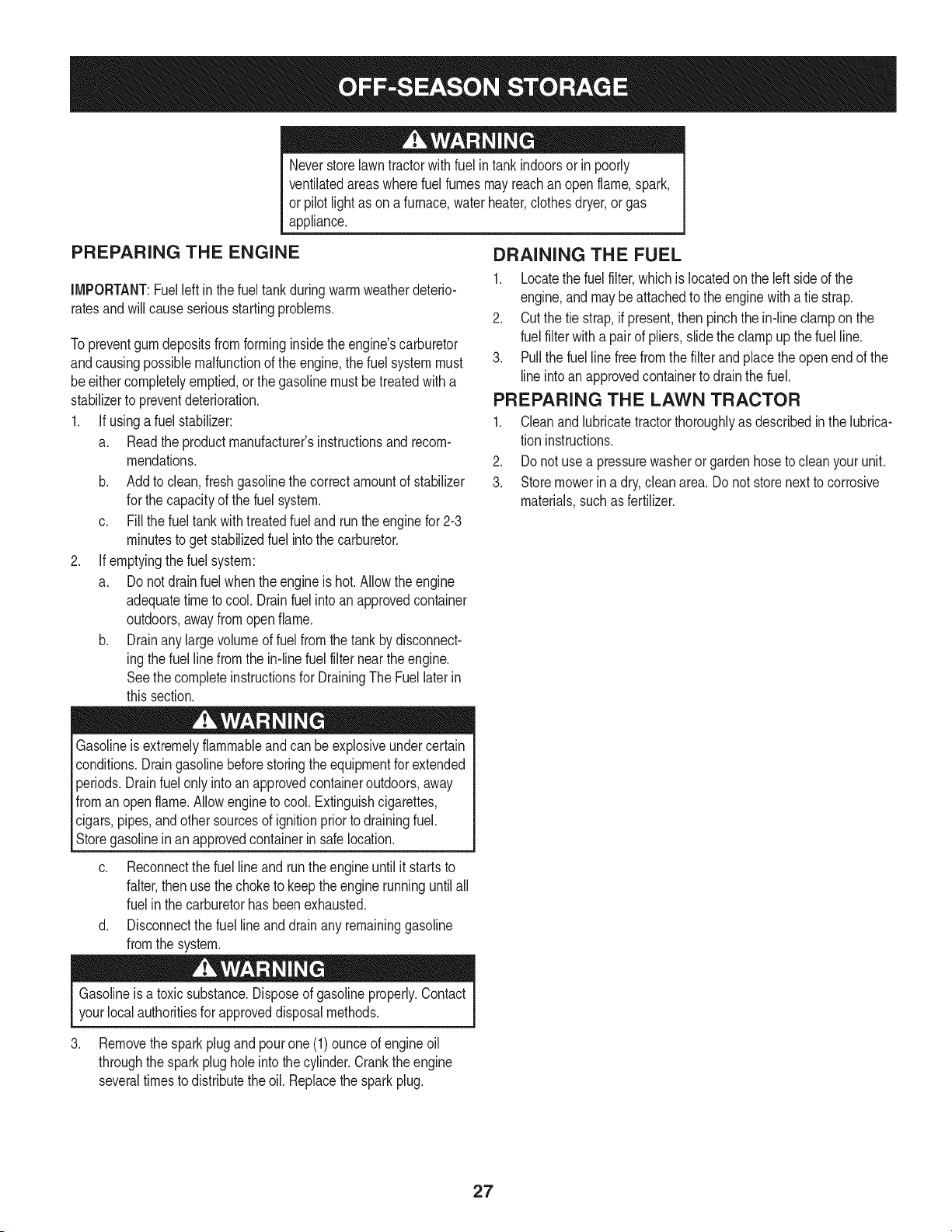
PREPARING THE ENGINE
IMPORTANT:Fuelleftin thefuel tankduringwarm weatherdeterio-
ratesandwill causeseriousstartingproblems.
To preventgumdepositsfromforminginsidethe engine'scarburetor
andcausingpossiblemalfunctionof theengine,thefuel systemmust
be eithercompletelyemptied,orthe gasolinemustbe treatedwith a
stabilizerto preventdeterioration.
1. Ifusingafuel stabilizer:
a. Readthe productmanufacturer'sinstructionsandrecom-
mendations.
b. Addto clean,freshgasolinethe correctamountof stabilizer
for the capacityof the fuel system.
c. Fillthe fueltank with treatedfuel andrunthe enginefor 2-3
minutesto get stabilizedfuel intothe carburetor.
2. Ifemptyingthe fuel system:
a. Donot drainfuel whenthe engineis hot. Allowthe engine
adequatetime to cool.Drainfuelinto an approvedcontainer
outdoors,awayfrom open flame.
b. Drainany largevolumeof fuel fromthetank bydisconnect-
ing thefuel linefrom the in-linefuel filter nearthe engine.
Seethe completeinstructionsfor DrainingThe Fuellaterin
this section.
Gasolineis extremelyflammableand can beexplosiveundercertain
conditions.Draingasolinebeforestoringthe equipmentfor extended
periods.Drainfuel only intoanapprovedcontaineroutdoors,away
froman openflame.Allowengineto cool. Extinguishcigarettes,
cigars,pipes,andothersourcesof ignitionpriorto drainingfuel.
Storegasolineinan approvedcontainerinsafelocation.
c. Reconnectthe fuel lineandrunthe engineuntil it starts to
falter,thenuse thechoketo keeptheengine runninguntilall
fuel in thecarburetorhas beenexhausted.
d. Disconnectthefuel lineand drainany remaininggasoline
fromthe system.
DRAiNiNG THE FUEL
1. Locatethe fuel filter,which is locatedonthe leftsideof the
engine,andmaybe attachedto the enginewith a tie strap.
2. Cutthe tie strap,if present,then pinchthe in-lineclamp on the
fuel filter with a pair of pliers,slidethe clamp up the fuel line.
3. Pullthe fuel line freefrom the filterandplacethe open end of the
lineintoanapprovedcontainerto drain the fuel.
PREPARING THE LAWN TRACTOR
1. Cleanand lubricatetractorthoroughlyas describedin the lubrica-
tion instructions.
2. Donot usea pressurewasheror gardenhoseto cleanyour unit.
3. Storemowerin a dry,cleanarea. Do notstore nextto corrosive
materials,suchas fertilizer.
Gasolineis a toxicsubstance.Disposeof gasolineproperly.Contact
your localauthoritiesfor approveddisposalmethods.
3. Removethe sparkplug andpourone(1)ounceof engineoil
throughthe sparkplug hole intothe cylinder.Cranktheengine
severaltimesto distributethe oil. Replacethe sparkplug.
27
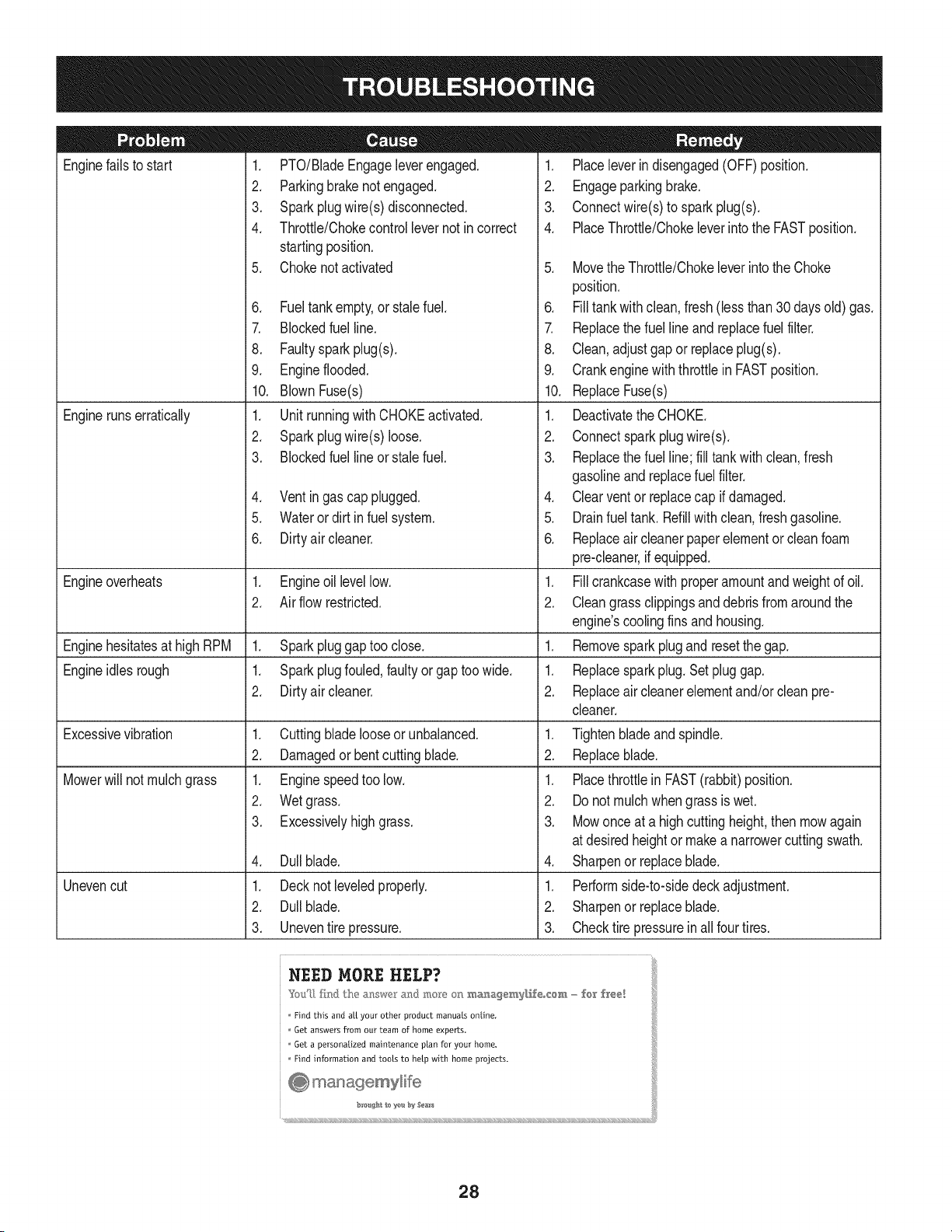
Enginefailsto start
Enginerunserratically
1. PTO/BladeEngageleverengaged.
2. Parkingbrakenotengaged.
3. Sparkplugwire(s)disconnected.
4. Throttle/Chokecontrollevernot incorrect
startingposition.
5. Chokenotactivated
6. Fueltankempty,or stalefuel.
7. BIockedfuelline.
8. Faultyspark plug(s).
9. Engineflooded.
10. BlownFuse(s)
1. Unitrunningwith CHOKEactivated.
2. Sparkplugwire(s)loose.
3. Blockedfuel lineor stalefuel.
4. Ventingas cap plugged.
5. Waterordirt infuel system.
6. Dirtyair cleaner.
Engineoverheats 1. Engineoillevellow. 1.
2. Airflow restricted. 2.
Enginehesitatesat highRPM 1. Sparkpluggaptoo close. 1.
Engineidles rough 1. Sparkplugfouled,faultyor gaptoo wide. 1.
2. Dirtyair cleaner. 2.
Excessivevibration
Mowerwill not mulchgrass
Unevencut
1. Cuttingbladelooseor unbalanced.
2. Damagedor bentcuttingblade.
1. Enginespeedtoo low.
2. Wetgrass.
3. Excessivelyhighgrass.
4. Dullblade.
1. Decknot leveledproperly.
2. Dullblade.
3. Uneventire pressure.
1. Placeleverindisengaged(OFF)position.
2. Engageparkingbrake.
3. Connectwire(s)to sparkplug(s).
4. PlaceThrottle/Chokeleverintothe FASTposition.
5. MovetheThrottle/Chokeleverintothe Choke
position.
6. Filltankwith clean,fresh (less than30 daysold) gas.
7. Replacethe fuel line and replacefuel filter.
8. Clean,adjustgapor replaceplug(s).
9. Crankenginewiththrottlein FASTposition.
10. ReplaceFuse(s)
1. Deactivatethe CHOKE.
2. Connectspark plugwire(s).
3. Replacethe fuel line;fill tank with clean,fresh
gasolineand replacefuel filter.
4. Clearventor replacecap if damaged.
5. Drainfuel tank. Refillwith clean,fresh gasoline.
6. Replaceair cleanerpaperelementor cleanfoam
pre-cleaner,if equipped.
Fillcrankcasewith properamountandweightof oil.
Cleangrassclippingsanddebrisfrom aroundthe
engine'scoolingfinsandhousing.
Removesparkplugand resetthe gap.
Replacesparkplug.Set pluggap.
Replaceair cleanerelementand/orclean pre-
cleaner.
1. Tightenbladeand spindle.
2. Replaceblade.
1. Placethrottlein FAST(rabbit)position.
2. Do notmulchwhengrass is wet.
3. Mowonce at a highcuttingheight,then mowagain
at desiredheightor makea narrowercuttingswath.
4. Sharpenor replaceblade.
1. Performside-to-sidedeck adjustment.
2. Sharpenor replaceblade.
3. Checktire pressureinallfour tires.
NEED MORE HELP?
Find this and aLLyour other product manuals online,
Get answers from our team of home experts.
Get a personalized maintenance plan for your home,
Find information and tools to help with home projects.
_o #At 1o ye b:_ Sea_s
28
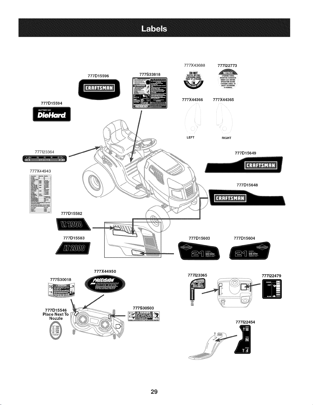
777D15594
777D15596
777S33818
777X43688 777122773
DONOT
USE EN5OR FUEL STEERINGWHEEL
CONTAININGMORE MOUNTINGHARDWARE
THAN 10% ETHANOL
UNDER CAR BEFORE
OPERATIONSECURE
STEERING WHEEL TO
SHAFT ACCORDING
TO MANUAL
777X44366 777X44365
LEFT RIGHT
777123364
777)(44943
777D15582
777D15649
777D15648
777D15583
777D15603 777D15604
777S30018
777X44950
777123365
777122479
777D15546
Place Next To
Nozzle
777S30503
777122454
29
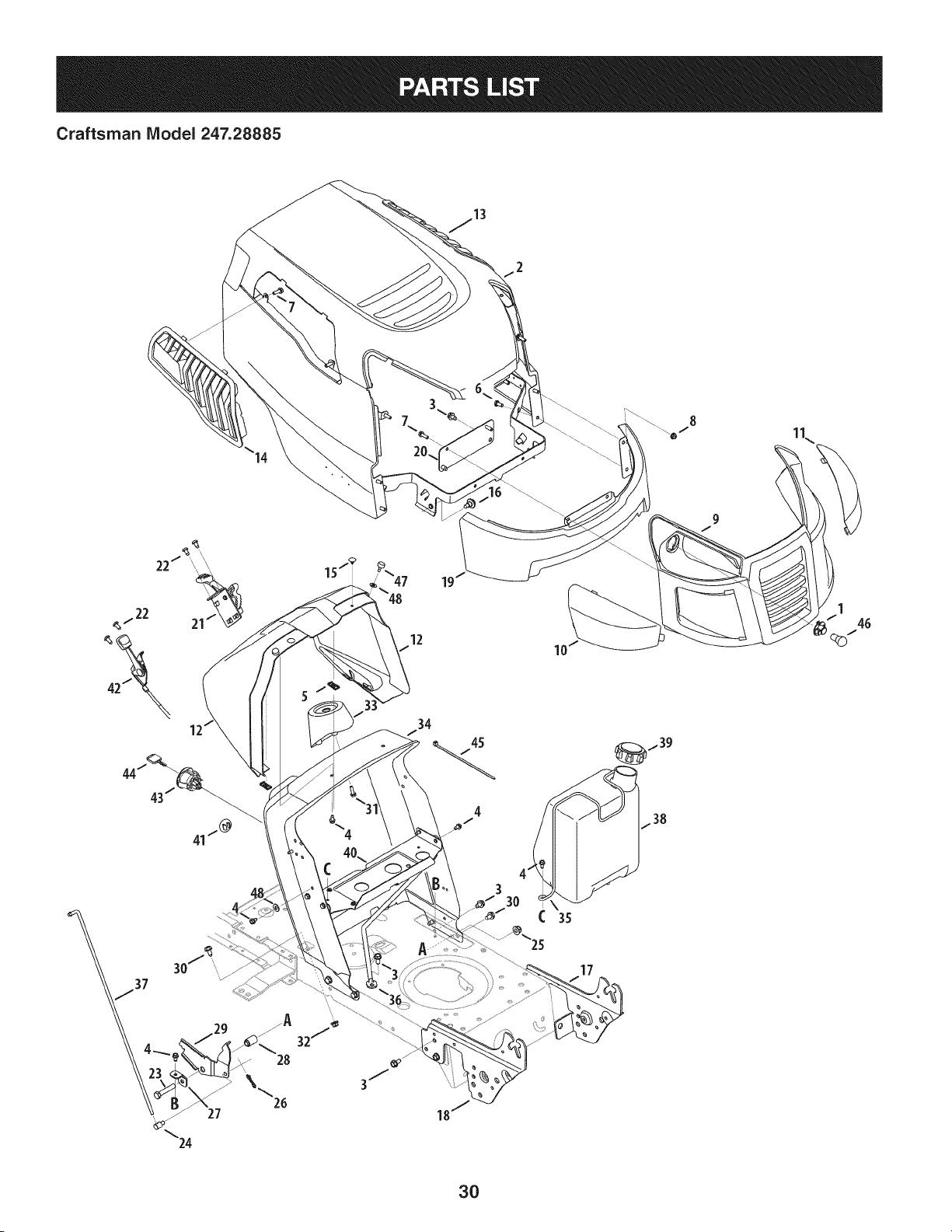
Craftsman IViodel 247.28885
12
10
17
3O
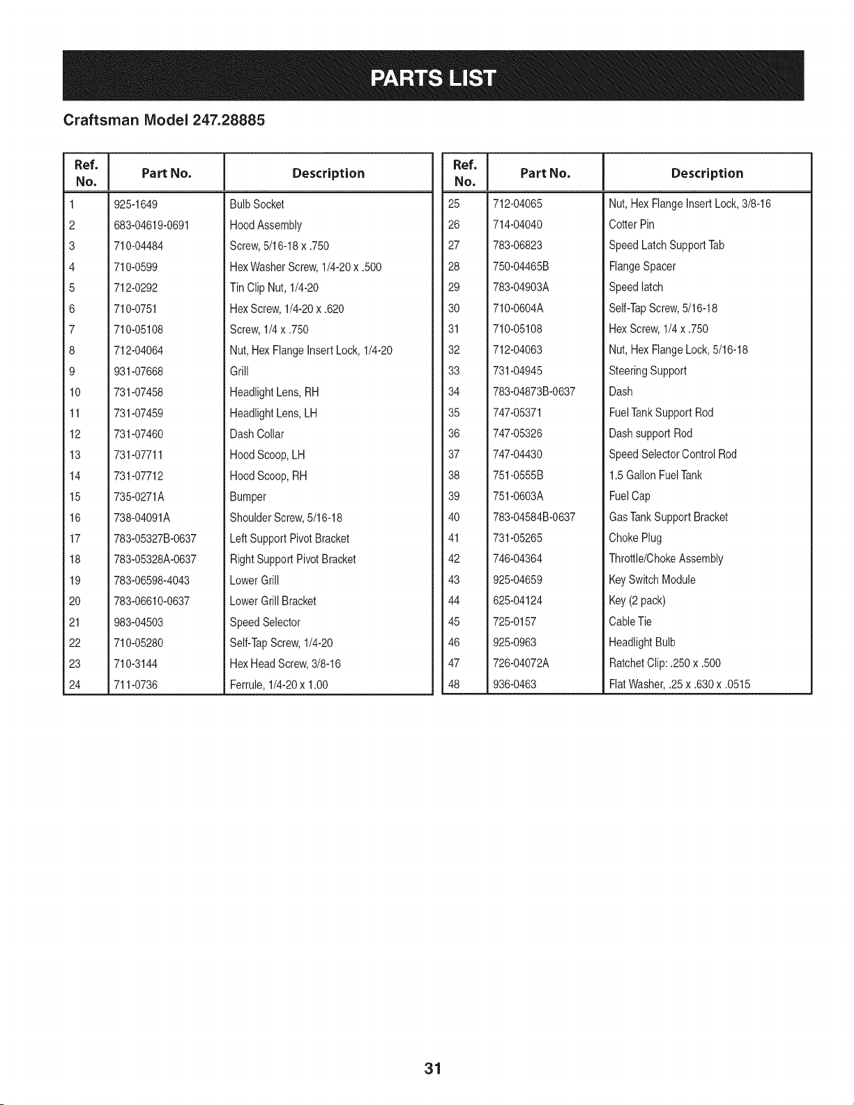
Craftsman Model 247.28885
Ref. I
No,
1 925-1649
2 683-04619-0691
3 710-04484
4 710-0599
5 712-0292
6 710-0751
7 710-05108
8 712-04064
9 931-07668
10 731-07458
11 731-07459
12 731-07460
13 731-07711
14 731-07712
15 735-0271A
16 738-04091A
17 783-05327B-0637
18 783-05328A-0637
19 783-06598-4043
20 783-06610-0637
21 983-04503
22 710-05280
23 710-3144
24 711-0736
Part No. Description
BulbSocket
HoodAssembly
Screw,5/16-18x .750
HexWasherScrew,1/4-20x .500
Tin Clip Nut, 1/4-20
HexScrew,1/4-20x .620
Screw,1/4x .750
Nut,HexFlangeInsert Lock,1/4-20
Grill
HeadlightLens,RH
HeadlightLens,LH
DashCollar
HoodScoop,LH
HoodScoop,RH
Bumper
ShoulderScrew,5/16-18
LeftSupport PivotBracket
RightSupportPivotBracket
LowerGrill
LowerGrill Bracket
SpeedSelector
Self-TapScrew,1/4-20
HexHeadScrew,3/8-16
Ferrule,1/4-20x 1.00
Ref. I
No,
25 712-04065
26 714-04040
27 783-06823
28 750-04465B
29 783-04903A
30 710-0604A
31 710-05108
32 712-04063
33 731-04945
34 783-04873B-0637
35 747-05371
36 747-05326
37 747-04430
38 751-0555B
39 751-0603A
40 783-04584B-0637
41 731-05265
42 746-04364
43 925-04659
44 625-04124
45 725-0157
46 925-0963
47 726-04072A
48 936-0463
Part No. Description
Nut, HexFlangeInsertLock,3/8-16
Cotter Pin
SpeedLatchSupportTab
FlangeSpacer
Speedlatch
Self-TapScrew,5/16-18
HexScrew,1/4x .750
Nut, HexFlangeLock,5/16-18
SteeringSupport
Dash
FuelTankSupport Rod
Dashsupport Rod
SpeedSelectorControl Rod
1.5GallonFuelTank
FuelCap
GasTankSupport Bracket
ChokePlug
Throttle/ChokeAssembly
KeySwitchModule
Key(2 pack)
CableTie
HeadlightBulb
RatchetClip: .250x .500
FlatWasher,.25 x .630x .0515
31
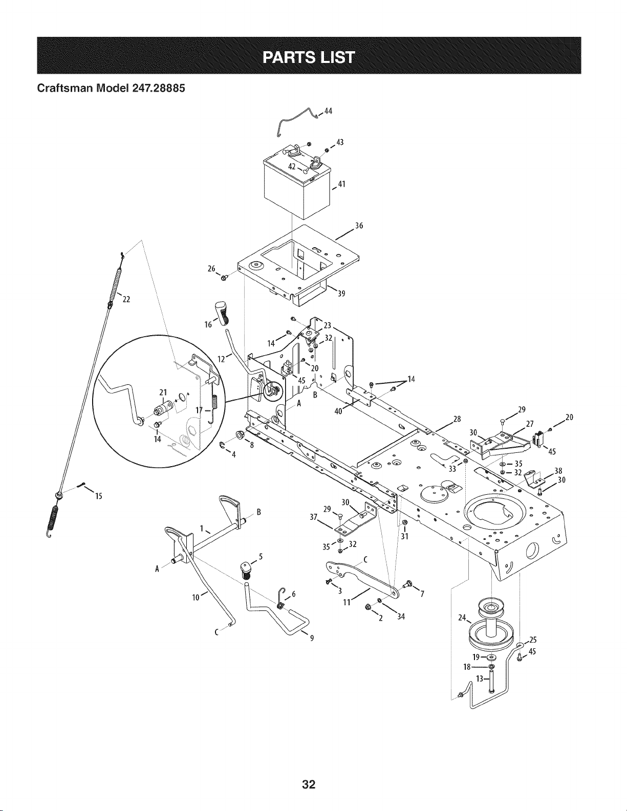
Craftsman IViodel 247.28885
15
21
14
37
29
45
30
32
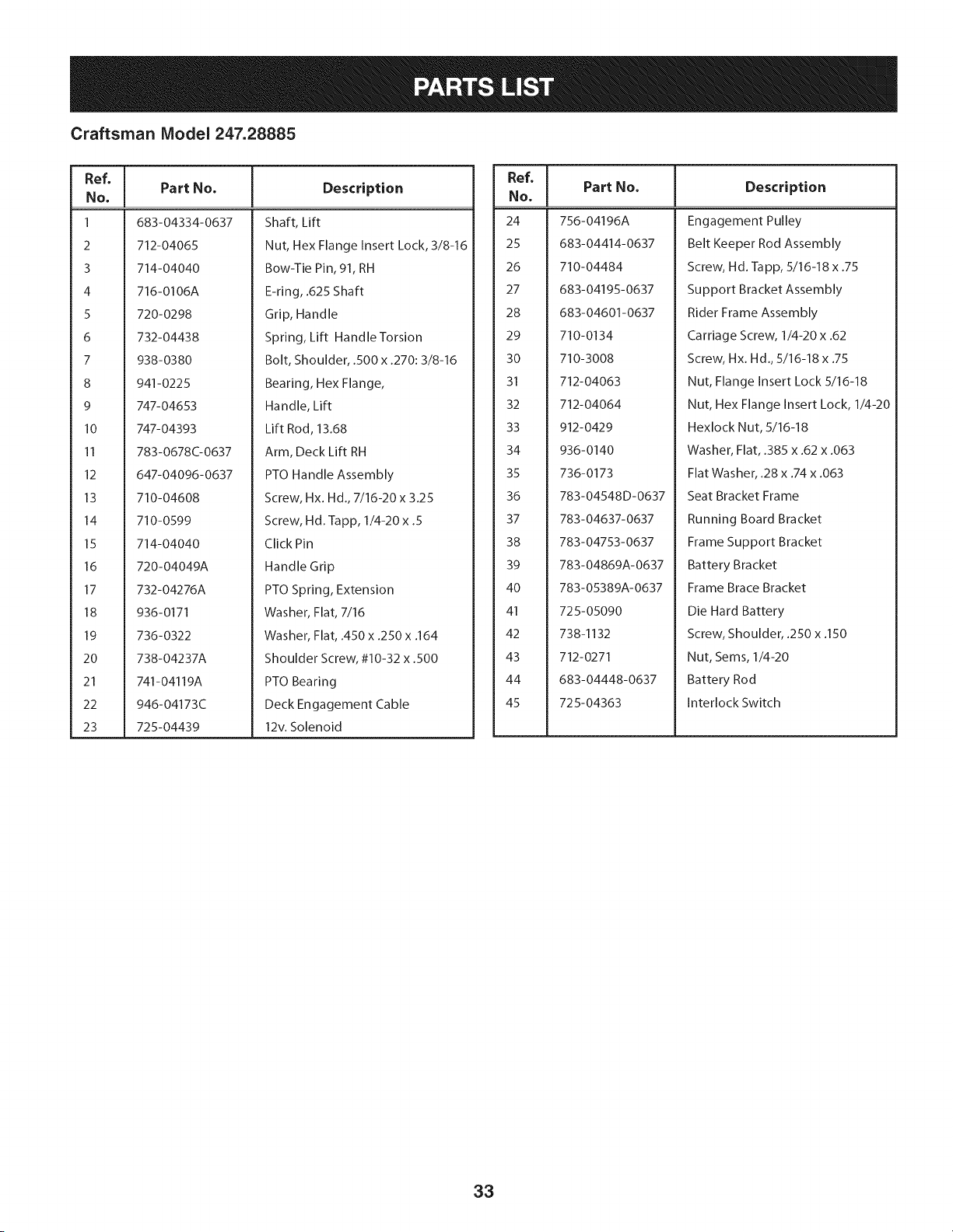
Craftsman Model 247.28885
Ref, ]
No,
1 683-04334-0637
2 712-04065
3 714-04040
4 716-0106A
5 720-0298
6 732-04438
7 938-0380
8 941-0225
9 747-04653
10 747-04393
11 783-0678C-0637
12 647-04096-0637
13 710-04608
14 710-0599
15 714-04040
16 720-04049A
17 732-04276A
18 936-0171
19 736-0322
20 738-04237A
21 741-04119A
22 946-04173C
23 725-04439
Part No, Description
Shaft, Lift
Nut, Hex Flange Insert Lock, 3/8-16
Bow-Tie Pin, 91, RH
E-ring, .625 Shaft
Grip, Handle
Spring, Lift Handle Torsion
Bolt, Shoulder, .500 x .270:3/8-16
Bearing, Hex Flange,
Handle, Lift
Lift Rod, 13.68
Arm, Deck Lift RH
PTO Handle Assembly
Screw, Hx. Hd., 7/16-20 x 3.25
Screw, Hd. lapp, 1/4-20 x .5
Click Pin
Handle Grip
PTO Spring, Extension
Washer, Flat, 7/16
Washer, Flat, .450 x .250 x .164
Shoulder Screw, #10-32 x .500
PTO Bearing
Deck Engagement Cable
12v. Solenoid
Ref, I
No,
24 756-04196A
25 683-04414-0637
26 710-04484
27 683-04195-0637
28 683-04601-0637
29 710-0134
30 710-3008
31 712-04063
32 712-04064
33 912-0429
34 936-0140
35 736-0173
36 783-04548D-0637
37 783-04637-0637
38 783-04753-0637
39 783-04869A-0637
40 783-05389A-0637
41 725-05090
42 738-1132
43 712-0271
44 683-04448-0637
45 725-04363
Part No, Description
Engagement Pulley
Belt Keeper Rod Assembly
Screw, Hd. Tapp, 5/16-18 x .75
Support Bracket Assembly
Rider Frame Assembly
Carriage Screw, 1/4-20 x .62
Screw, Hx. Hd., 5/16-18 x .75
Nut, Flange Insert Lock 5/16-18
Nut, Hex Flange Insert Lock, 1/4-20
Hexlock Nut, 5/16-18
Washer, Flat, .385 x .62 x .063
Flat Washer, .28 x .74 x .063
Seat Bracket Frame
Running Board Bracket
Frame Support Bracket
Battery Bracket
Frame Brace Bracket
Die Hard Battery
Screw, Shoulder, .250 x .150
Nut, Seres, 1/4-20
Battery Rod
Interlock Switch
33
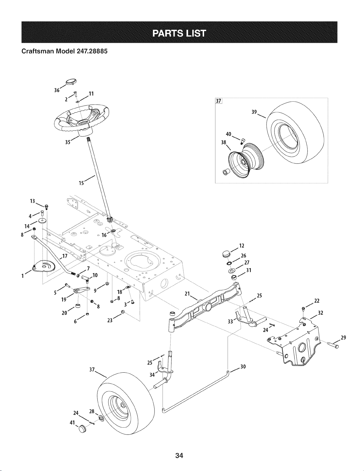
Craftsman IViodel 247.28885
24 28
41
24_ ..........
29
34
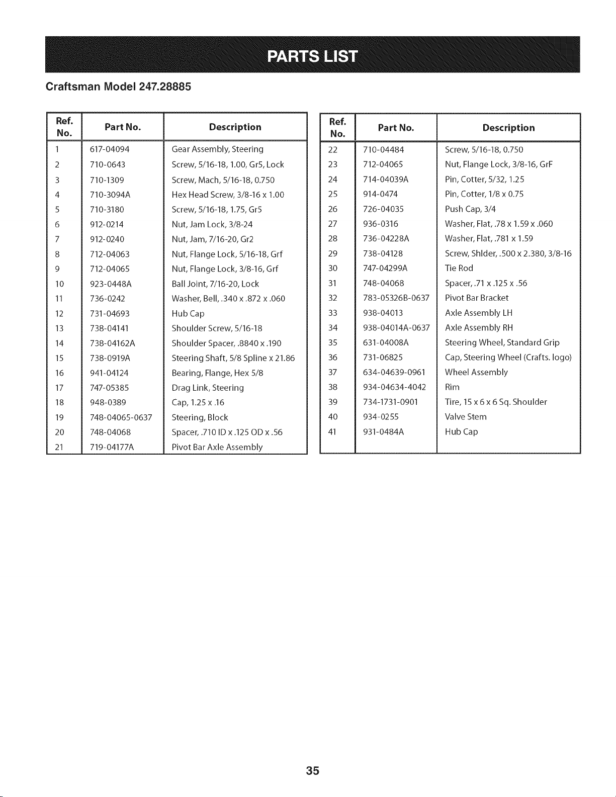
Craftsman Model 247.28885
Ref, I
No,
1 617-04094
2 710-0643
3 710-1309
4 710-3094A
5 710-3180
6 912-0214
7 912-0240
8 712-04063
9 712-04065
10 923-0448A
11 736-0242
12 731-04693
13 738-04141
14 738-04162A
15 738-0919A
16 941-04124
17 747- 05385
18 948-0389
19 748-04065-0637
20 748-04068
21 719-04177A
Part No. Description
Gear Assembly, Steering
Screw, 5/16-18, 1.00, GrS, Lock
Screw, Mach, 5/16-18, 0.750
Hex Head Screw, 3/8-16 x 1.00
Screw, 5/16-18, 1.75, Gr5
Nut, Jam Lock, 3/8-24
Nut, Jam, 7/16-20, Gr2
Nut, Flange Lock, 5/16-18, Grf
Nut, Flange Lock, 3/8-16, Grf
Ball Joint, 7/16-20, Lock
Washer, Bell, .340 x .872 x .060
Hub Cap
Shoulder Screw, 5/16-18
Shoulder Spacer, .8840 x .190
Steering Shaft, 5/8 Spline x 21.86
Bearing, Flange, Hex 5/8
Drag Link, Steering
Cap, 1.25 x .16
Steering, Block
Spacer, .710 ID x .125 OD x .56
Pivot Bar Axle Assembly
Ref, I
No,
22 710-04484
23 712-04065
24 714-04039A
25 914-0474
26 726-04035
27 936-0316
28 736-04228A
29 738-04128
30 747-04299A
31 748-04068
32 783-05326B-0637
33 938-04013
34 938-04014A-0637
35 631-04008A
36 731-06825
37 634-04639-0961
38 934-04634-4042
39 734-1731-0901
40 934-0255
41 931-0484A
Part No. Description
Screw, 5/16-18, 0.750
Nut, Flange Lock, 3/8-16, GrF
Pin, Cotter, 5/32, 1.25
Pin, Cotter, 1/8 x 0.75
Push Cap, 3/4
Washer, Flat, .78 x 1.59 x .060
Washer, Flat, .781 x 1.59
Screw, Shlder, .500 x 2.380, 3/8-16
Tie Rod
Spacer, .71 x .125 x .56
Pivot Bar Bracket
Axle Assembly LH
Axle Assembly RH
Steering Wheel, Standard Grip
Cap, Steering Wheel (Crafts. logo)
Wheel Assembly
Rim
Tire, 15 x6x 6 Sq. Shoulder
Valve Stem
Hub Cap
35
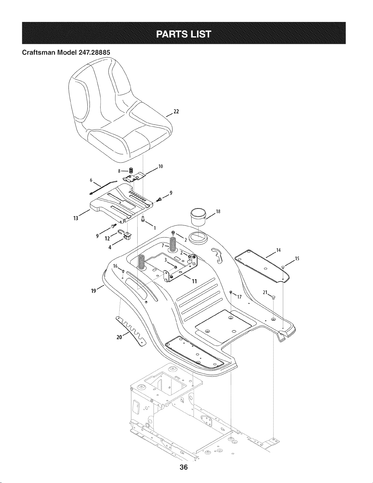
Craftsman Model 247.28885
13
\
11
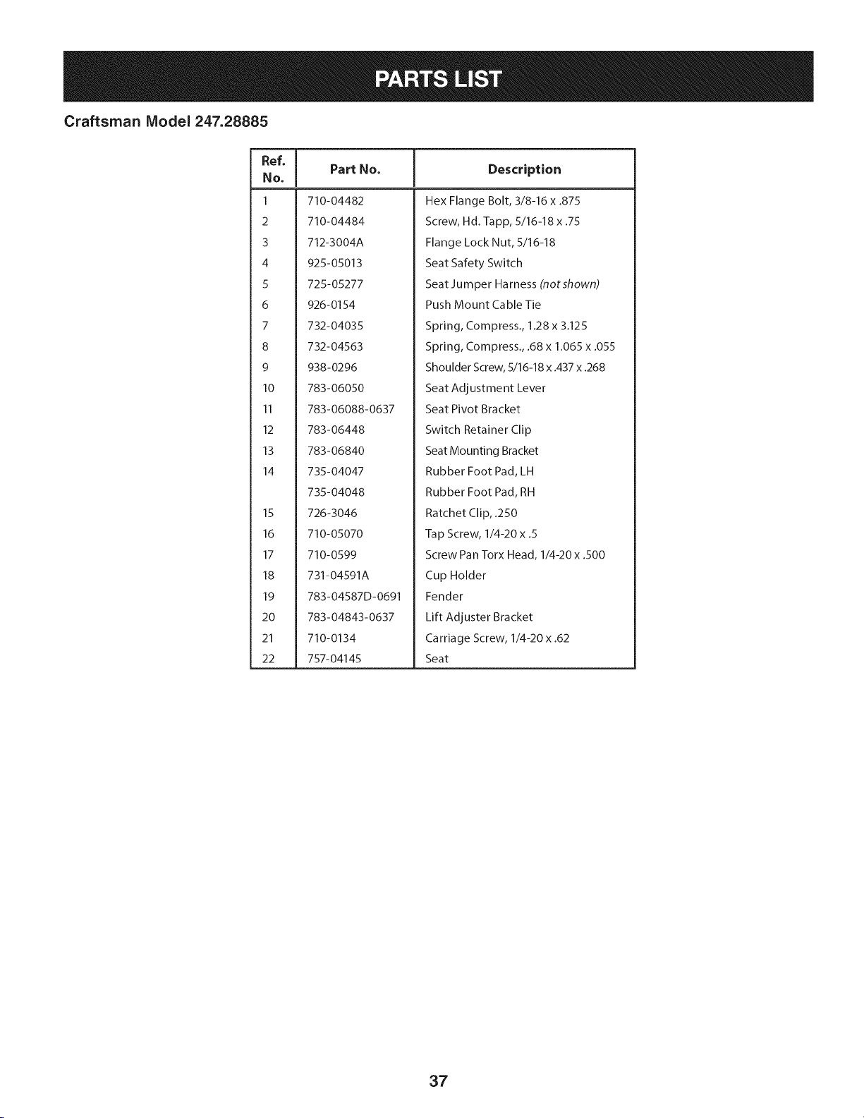
Craftsman Model 247.28885
Ref, [
No,
I 710-04482
2 710-04484
3 712-3004A
4 925-05013
5 725-05277
6 926-0154
7 732-04035
8 732-04563
9 938-0296
10 783-06050
11 783-06088-0637
12 783-06448
13 783-06840
14 735-04047
735-04048
15 726-3046
16 710-05070
17 710-0599
18 731-04591A
19 783-04587D-0691
20 783-04843-0637
21 710-0134
22 757-04145
Part No. Description
Hex Flange Bolt, 3/8-16 x .875
Screw, Hd.-lapp, 5/16-18 x .75
Flange Lock Nut, 5/16-18
Seat Safety Switch
Seat Jumper Harness (notshown)
Push Mount Cable Tie
Spring, Compress., 1.28 x 3.125
Spring, Compress., .68 x 1.065 x .055
Shoulder Screw, 5/16-18 x .437 x .268
Seat Adjustment Lever
Seat Pivot Bracket
Switch Retainer Clip
Seat Mounting Bracket
Rubber Foot Pad, LH
Rubber Foot Pad, RH
Ratchet Clip, .250
Tap Screw, 1/4-20 x .5
Screw Pan Torx Head, 1/4-20 x .500
Cup Holder
Fender
Lift Adjuster Bracket
Carriage Screw, 1/4-20 x .62
Seat
37
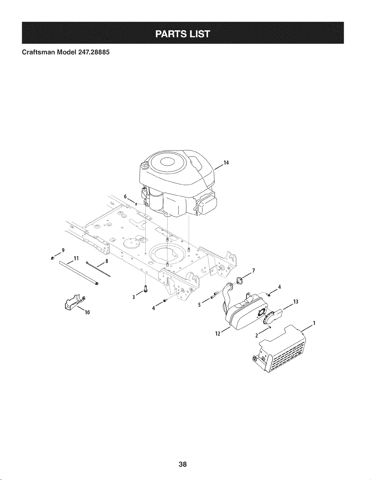
Craftsman IViodel 247.28885
13
38

Craftsman IViodel 247.28885
I
Ref.
I Part No.
1 683-04549-0637
2 710-0227
3 710-04683
4 710-0642
5 710-1314A
6 712-0271
7 BS-692236
8 725-0157
9 726-0205
10 731-05628
11 751-10349
12 751-10448B
13 751-10353
14 331877-0869-G5
Descriptien
MufflerShieldAssembly
Screw,AB #8-180.500
TapScrew,3/8-16 1.000
TapScrew,1/4-200.750
Screw,SocketHead,5/16-18x .750
Sems Nut, 1/4-20
ExhaustGasket
CableTie,3/16 X .05 X 7.4
HoseClamp,.490 Dia.
Oil DrainSleeve
LowPermeationFuelHose,1/4
BriggsSingleMuffler
LongMufflerDeflector
Engine
39
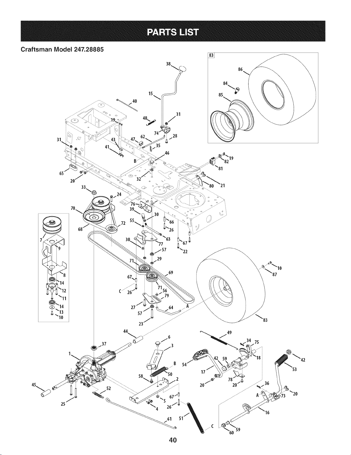
Craftsman Model 247.28885
41
15
35
19
29
B 54
17
4O
20/_

Craftsman Model 247.28885
I
Ref, I Part No.
1 918-04566
2 683-04606
3 683-04684
4 710-1260A
5 712-04065
6 738-0322A
7 956-04015A
8 683-04522
9 683-04612-0637
10 710-0627
11 710-0778
12 718-04261
13 736-0362
14 941-0600
15 647-04035
16 647-04201-0637
17 647-04203A-0637
18 683-04607
19 710-0227
20 710-04484
21 710-0604A
22 710-0809
23 710-0859
24 710-1007
25 710-1266
26 710-1325
27 710-1858A
28 710-3008
29 912-0240
30 712-0241
31 712-04063
32 912-0431
33 712-0700
34 914-Olll
35 914-0209
36 714-04040
37 718-04407
38 720-04028
39 923-3018
40 725-0157
41 725-1644
42 726-0214
43 926-0320
44 731-04602
Description
Dr Assembly, Autodrive Lt-5
Auto-drive Bracket Assembly
Idler Bracket Assembly
Tap Screw, 5/16-18 x 0.750
Flange Lock Nut, 3/8-16
Shoulder Screw, .625 x .217
Pulley Assembly, Var. Spd. 4.75 Od
Belt Keeper Assembly
Variable Bracket Assembly
Hex Screw 5/16-24.750
Tap Screw, 1/4-20 1.500
Bearing Cup
Wash, Flat .330 X 1.25 X .06
Ball Bearing, 17 x 40 x 12.6203
Lvr Assembly, Shft
Ped Assembly, Drive, Autodrive
Ped Assembly, Cont, Autodrive
Bracket Assembly, Pedal, Autodrive
Screw, Ab, #8-18, 0.500
Screw, Tt, 5/16-18, .750
Screw, Tt, 5/16-18, 0.625
Screw, Tt, 1/4-20, 1.250
Hex Hd. Screw, 3/8-16, 2.50
Screw, Ttsems, 3/8-16, 1.500
Hex Hd. Screw, 5/16-18, 3.50
Screw, Tt, 1/4-20, 1.625,
Screw, Tt, 3/8-16 x 1.75
Hex Hd. Screw, 5/16-18, .75
Nut, Jam, 7/16-20
Nut, Hex, 3/8-24
Nut, Flange Lock Nut, 5/16-18
Nut, Flange Lock Nut, 3/8-16
Nut, Fig, 9/16-18
Pin, Cot, 3/32, 1.0
Pin, Cotter Int- .125 Dia
Pin, Cot, Bow-Tie 72
Hub, Pulley, 5/8 Spline
Knob, Shft
Bali,Joint
Cable, Tie, 3/16 X .05 X 7.4
Switch, Spring, Short
Cap, Push 5/8
Plate, Insulator Nut
Sleeve, .758 X .821 X 3.3125
|
Ref, I Part No,
45 731-04604
46 731-06330
47 731-06894
48 732-04488
49 732-04612
50 732-04616B
51 732-04764
52 732-0716D
53 735-0239
54 735-0662
55 936-0169
56 936-0185
57 738-0372B
58 738-04091A
59 741-0495
60 741-3065B
61 747-05188
62 747-05243
63 747-05251A
64 747-05415
65 948-0334
66 750-04456
67 750-0566A
68 954-04208
69 954-0467A
70 956-04002
71 756-04224
72 756-04325
73 783-04536B-0637
74 783-04595A
75 783-06278
76 783-06562-0637
77 783-06592A
78 783-06641
79 783-06769
80 783-06807
81 725-04363
82 17962
83 634-04641-0961
84 634-04369-4042
85 934-0255
86 734-1729
87 736-0242
-- 925-04082
Description
Sleeve, .758 X .821 X 2.4375
Plug, Deck Hole, 7/8
Shift Plate Bearing
Spring, Ext, .38 Od X 3.25 Lg
Spring, Extn, .70 Dia X 12.00 Lg
Spring, Extn, .97 Od X 6.18 Lg
Spring, Extn, .56 X 12.05 x .068
Spring, Extn, .59 Od X 4.00 Lg
Pad, Foot, 4.0 Long
Pad, Cont
Wash, Lock, 3/8, Regular Duty
Wash, Flat, .375 X .738 X .063
Spacer, Shoulder, 1.00 X .38 X .38
Screw, Shoulder, A3x.29, Tt, 5/16-18
Bearing, Fig, .630 Idx .695 Od X .60
Bearing, Hex Fig, .628 Id, Split
Rod, Brake, Lt-5 Trans
Rod, Shift, Lt-5 Stretch 46"
Rod, Adj, Idlr, 3/8
Rod, Trans, Footpedal Bypass
Spacer, T-Axle .68
Spacer, .260 X .372 X 1.420 Lg
Spacer, .260 X .375 X 1.030 Lg
Belt, V Typ, 51 X 40.9 Lg Poly
Belt, V Typ, 51,90.80, Poly
Pulley, Idlr, Flat 7.25 Od
Pulley, Idlr, Flat 2.75 Od
Pulley, Idlr, V-Type X 3.06
Bracket, Ped, Support Lt-5
Bracket, Shft, Adj
Pit, Bracket, Reinforcement
Bracket, Ped, Frame Rh
Bracket, Idlr, Dbl Autodrive
Bracket, Supt, Pedal Stap
Bracket, Idlr, Center Dbl
Pedal Stop Plate
Interlock Switch
Switch Plate
Wheel Assembly, 18 x 9.5 x 8 Sq. Sh.
Rim Assembly
Valve Stem
Tire, 18x9.5 x8 Sq. Sh.
Bell Washer, .340 x .872 x .060
Wiring Harness (NotShown)
41
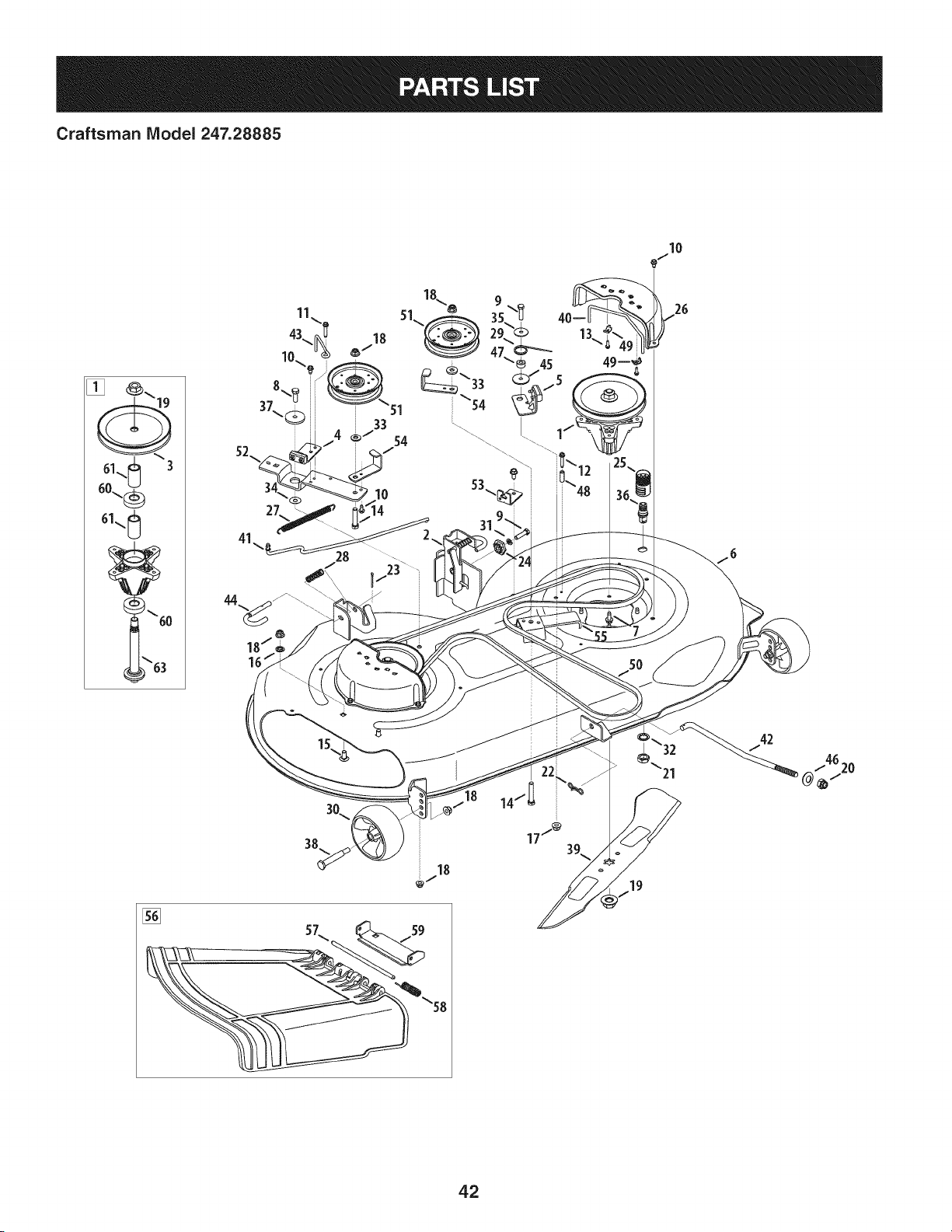
Craftsman Model 247.28885
I0
18
42
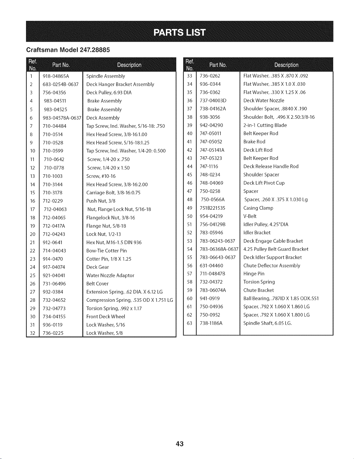
Craftsman Model 247.28885
1
2
3
4
5
6
7
8
9
10
11
12
13
14
15
16
17
18
19
20
21
22
23
24
25
26
27
28
29
3O
31
32
918-04865A
683-0254B-0637
756-04356
983-04511
983-04525
983-04578A-0637
710-04484
710-0514
710-0528
710-0599
710-0642
710-0778
710-1003
710-3144
710-3178
712-0229
712-04063
712-04065
712-0417A
712-04243
912-0641
714-04043
914-0470
917-04074
921-04041
731-06496
932-0384
732-04652
732-04773
734-04155
936- 0119
736-0225
Spindle Assembly
Deck Hanger Bracket Assembly
Deck Pulley, 6.93 DIA
Brake Assembly
Brake Assembly
Deck Assembly
Tap Screw, Ind. Washer, 5/16-18:.750
Hex Head Screw, 3/8-16:1.00
Hex Head Screw, 5/16-18:1.25
Tap Screw, Ind. Washer, 1/4-20:0.500
Screw, 1/4-20 x .750
Screw, 1/4-20 x 1.50
Screw, #10-16
Hex Head Screw, 3/8-16:2.00
Carriage Bolt, 3/8-16:0.75
Push Nut, 3/8
Nut, Flange Lock Nut, 5/16-18
Flangelock Nut, 3/8-16
Flange Nut, 5/8-18
Lock Nut, 1/2-13
Hex Nut, M16-1.5 DIN 936
Bow-Tie Cotter Pin
Cotter Pin, 1/8 X 1.25
Deck Gear
Water Nozzle Adaptor
Belt Cover
Extension Spring, .62 DIA. X 6.12 LG
Compression Spring, .535 OD X 1.751 LG
Torsion Spring, .992 x 1.17
Front Deck Wheel
Lock Washer, 5/16
Lock Washer, 5/8
m
@l
33
34
35
36
37
38
39
4O
41
42
43
44
45
46
47
48
49
5O
51
52
53
54
55
56
57
58
59
6O
61
62
63
736-0262
936-0344
736-0362
737-04003D
738-04162A
938-3056
942-04290
747-05011
747-05052
747-05141A
747-05323
747-1116
748-0234
748-04069
750-0258
750-0566A
751B221535
954-04219
756-04129B
783-05946
783-06243-0637
783-06368A-0637
783-06643-0637
631-04460
711-04847B
732-04372
783-06074A
941-0919
750-04936
750-0952
738-1186A
Flat Washer, .385 X .870 X .092
Flat Washer, .385 X 1.0 X .030
Flat Washer, .330 X 1.25 X .06
Deck Water Nozzle
Shoulder Spacer, .8840 X .190
Shoulder Bolt, .496 X 2.50:3/8-16
2-in-1 Cutting Blade
Belt Keeper Rod
Brake Rod
Deck Lift Rod
Belt Keeper Rod
Deck Release Handle Rod
Shoulder Spacer
Deck Lift Pivot Cup
Spacer
Spacer, .260 X .375 X 1.030 Lg
Casing Clamp
V-Belt
Idler Pulley, 4.25"DIA
Idler Bracket
Deck Engage Cable Bracket
4.25 Pulley Belt Guard Bracket
Deck Idler Support Bracket
Chute Deflector Assembly
Hinge Pin
Torsion Spring
Chute Bracket
Ball Bearing, .7871D X 1.85 ODX.551
Spacer, .792 X 1.060 X 1.860 LG
Spacer, .792 X 1.060 X 1.800 LG
Spindle Shaft, 6.05 LG.
43
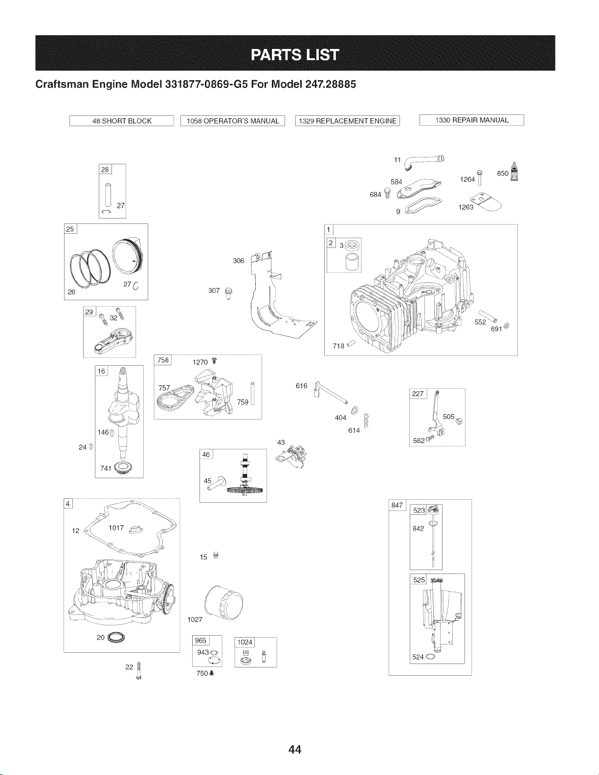
Craftsman Engine Model 331877=0869=G5 For Model 247.28885
48 SHORT BLOCK
1058 OPERATOR'S MANUAL ] I1329 REPLACEMENT ENGINE ]
1330 REPAIR MANUAL
26
12 1017_i_2__'_ _-'-.__i i
200
22
306
307
U
k _
15 _
1027
75O &
43
616
11 ,_
584 ..-/_. __ 1264
9 _ 1263 _-. y
552 _
691 _
718
404 ion.,505
614 _-,'-_¢,_
562 _ _"
847 _
524 d_7,
44
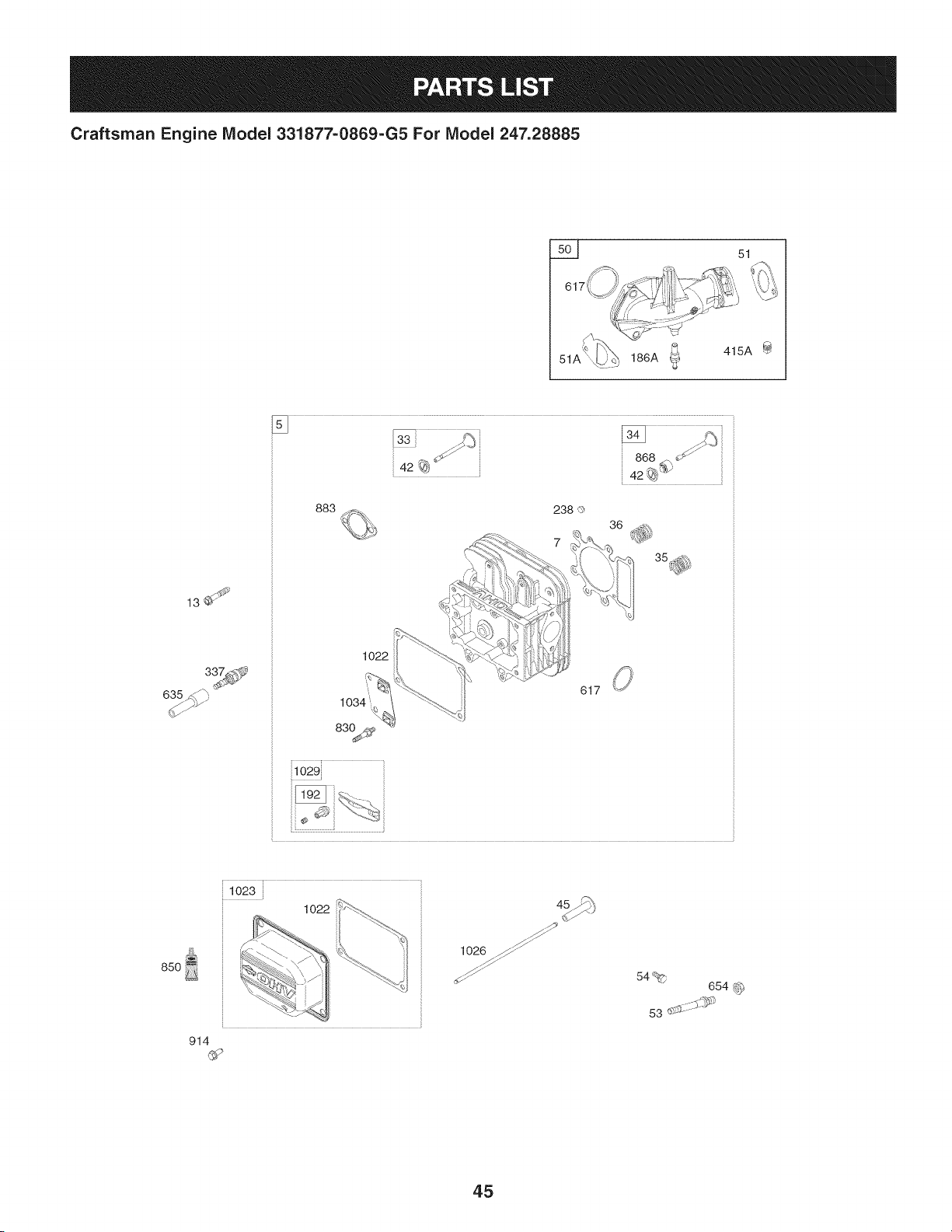
Craftsman Engine Model 331877=0869=G5 For Model 247.28885
5__ 51
51A
186A _ 415A
13_
635_
883
1022
617
i1029}
85O
102
914
1026 _
54%
654 _
53 .......
45
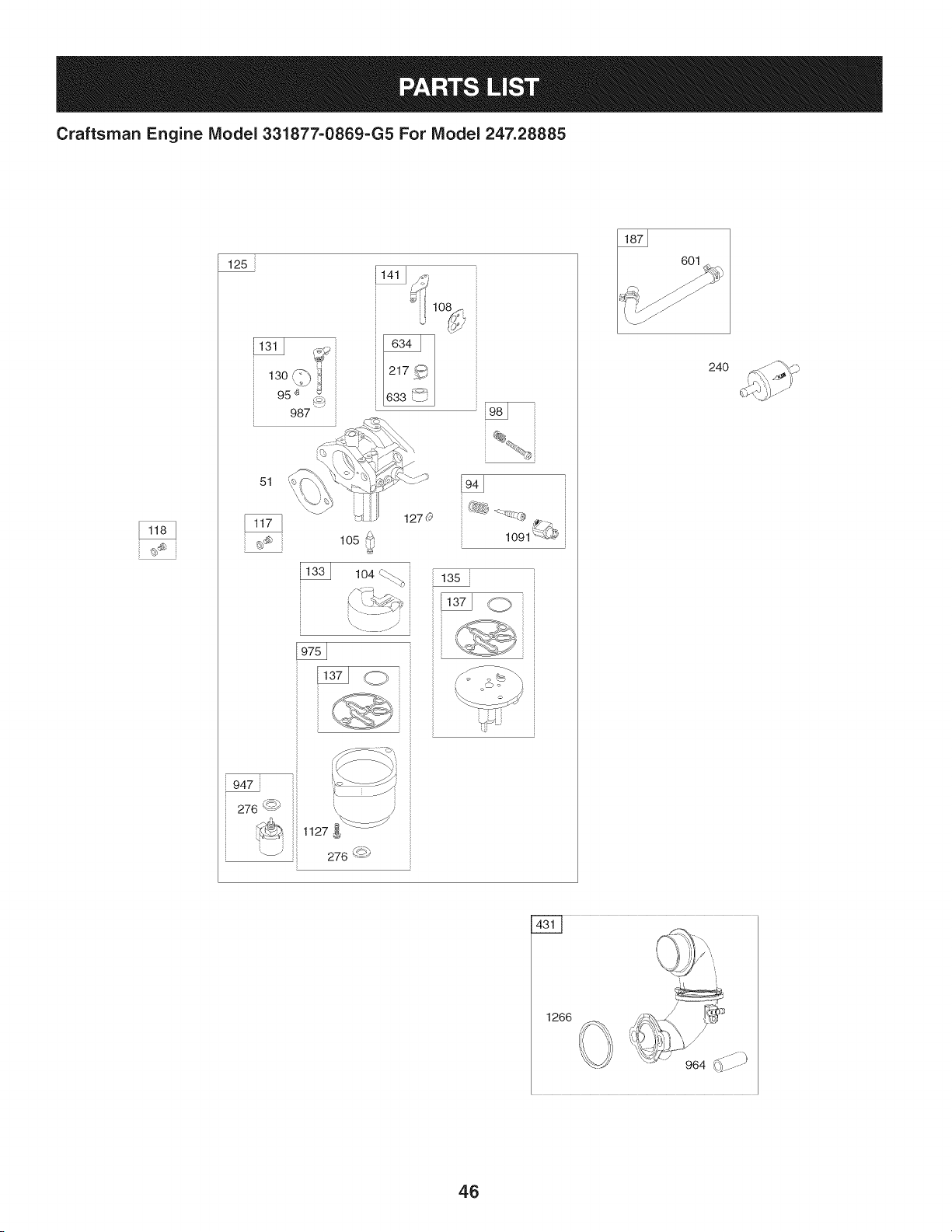
Craftsman Engine Model 331877-0869-G5 For Model 247.28885
125
13o 1
95 '_ _
987
51
lO2
1270
1091 {{L#
947
276 <_')
_ 1127
_ 276 '-<_
601
24O
1266
46
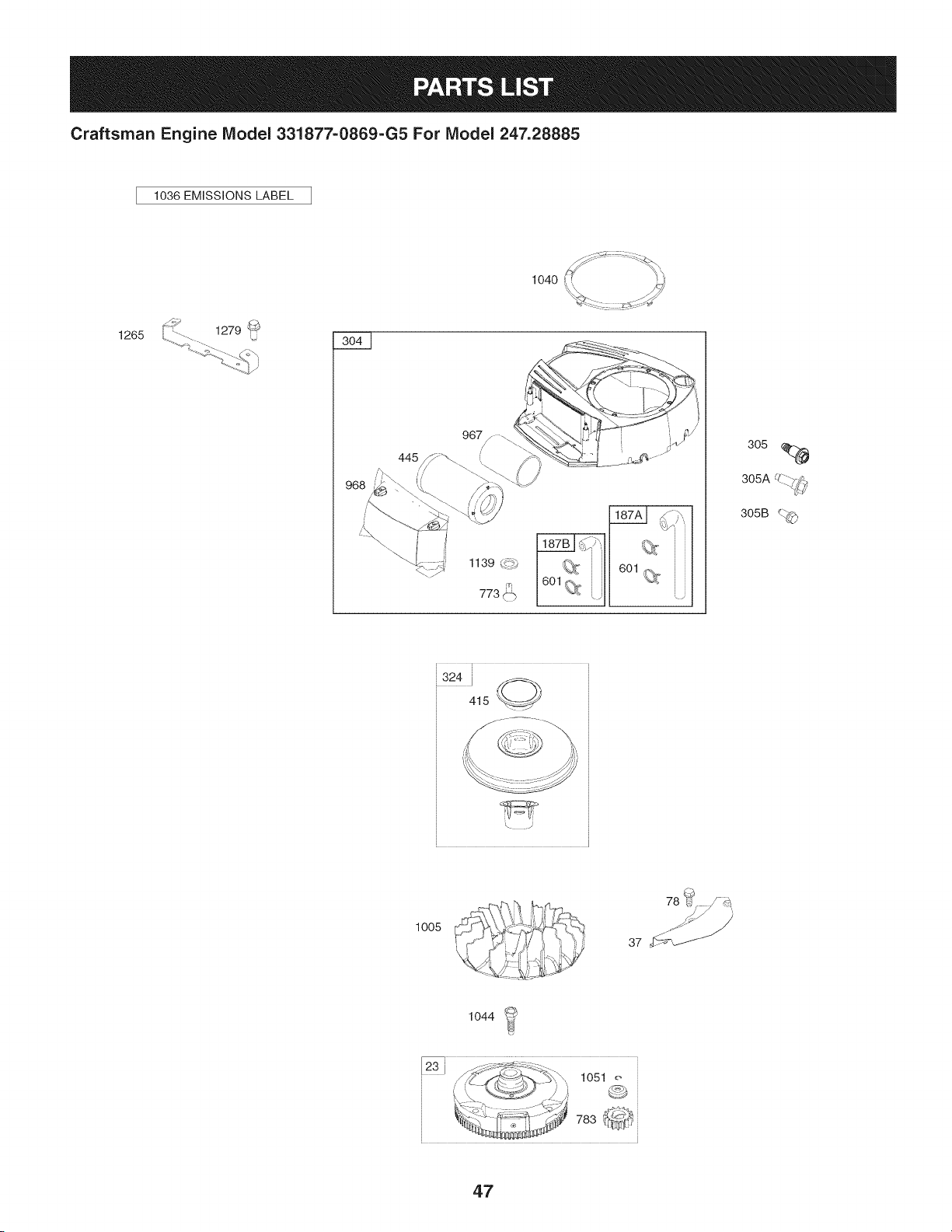
Craftsman Engine IViodel 331877=0869=G5 For IViodel 247.28885
1036 EMiSSiONS LABEL
1265
1139 _._,
305
UZ_--..
305A -.. 7_',
305B _._
,324 i _,
415 _//
:!!!i!!--_
\ .J
1005
78 _¢
37 '_f_
1044
47
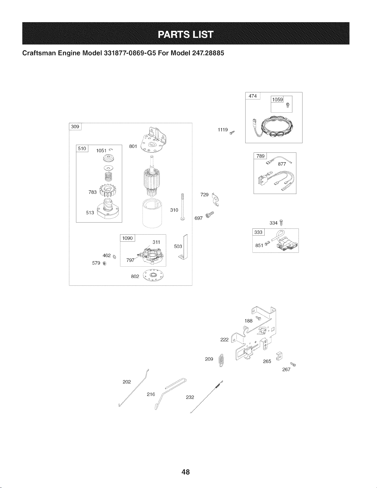
Craftsman Engine IViodel 331877-0869-G5 For IViodel 247.28885
309
1051 <"
783
513
801
310 iii
462 _;
579 _
802
729
697 _
1119
474
334
851
216
2O9
,,,_/ 232
265
267
48
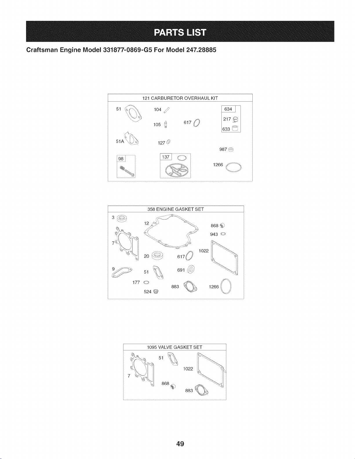
Craftsman Engine Model 331877=0869=G5 For Model 247.28885
51
121 CARBURETOR OVERHAUL KIT
104 _lO50 61__,
127 (_'
987 4_b
, 1266 _ ;_" ;_
ti
/
358 ENGINE GASKET SET
12
1o22
,_
691 _'7//'
1266
1095 VALVE GASKET SET
51
1022
49

Craftsman Engine Model 331877=0869=G5 For Model 247.28885
I
Ref.
I Part No.
NO,
I
1 794128
2 399265
3 391086s
4 697188
5 796026
7 794114
9 697109
11 794683
12 697110
13 793988
15 690946
16 797579
20 795387
22 692125
23 698281
24 796335
25 795858
795877
26 794126
794127
27 698469
28 795861
29 794122
32 791118
33 792868
34 791935
35 691279
36 691279
37 699882
42 499586
43 691968
45 690564
46 793880
48 795446
50 796180
51 692137
51A 794312
53 690227
54 691148
78 691693
94 793610
95 690718
Description
Cylinder Assembly
Bushing/Seal Kit (Magneto Side)
Seal-Oil (Magneto Side)
Sump-Engine
Head-Cylinder
Gasket-Cylinder Head
Gasket-Breather
Tube-Breather
Gasket-Crankcase
Screw (Cylinder Head)
Plug-Oil Drain
Crankshaft
Seal-Oil (PTO Side)
Screw (Crankcase Cover/Sump)
Flywheel
Key-Flywheel (Steel)
Piston Assembly (Standard)
Piston Assembly (020" Oversize)
Ring Set (Standard)
Ring Set (.020" Oversize)
Lock-Piston Pin
Pin-Piston
Rod-Connecting
Screw (Connecting Rod)
Valve-Exhaust
Valve-Intake
Spring-Valve (Intake)
Spring-Valve (Exhaust)
Guard-Flywheel
Keeper-Valve
Slinger-Governor/Oil
Tappet-Va Ive
Camshaft
Short Block
Manifold-Intake
Gasket-Intake
Gasket-Intake
Stud (Carburetor)
Screw (Intake Manifold)
Screw (Flywheel Guard)
Kit-Idle Mixture
Screw (Throttle Valve)
Ref,
No,
98 695408
104 694918
105 696136
108 695419
117 796251
118 791406
121 796184
125 796587
127 690727
130 792747
131 792765
133 694914
135 698780
137 698781
141 792777
146 691639
186 794873
187 791805
187A 791806
187B 791744
188 691693
192 691986
202 691841
209 692208
216 691840
217 695409
222 694042
227 691374
232 691842
238 691843
240 394358s
265 691024
267 794904
276 695410
304 798670
305 697102
305A 793376
305B 795891
306 794953
307 691693
309 693551
I Part No, Description
Kit-Idle Speed
Pin-Float Hinge
Valve-Float Needle
Valve-Choke
Jet-Main (Standard)
Jet-Main (High Altitude)
Kit-Carburetor Overhaul
Carburetor
Plug-Welch
Va Ive-Th rottle
Kit-Throttle Shaft
Float-Carburetor
Tube-Fuel Transfer
Gasket-Float Bowl
Kit-Choke Shaft
Key-Timing
Hose-Connector (Intake Manifold)
Line-Fuel (Formed) (Cut to Length)
Line-Fuel (Formed) (21") (Cut to Length)
Line-Fuel (Formed) (14") (Cut to Length)
Screw (Control Bracket)
Adjuster-Rocker Arm
Link-Mechanical Governor
Spring-Governor (Green)
Link-Choke
Spring-Choke Return
Bracket-Control
Lever-Governor Control
Spring-Governor Link
Cap-Valve
Filter-Fuel
Clamp-Casing
Screw (Casing Clamp)
Washer-Sealing
Housing-Blower
Screw (Blower Housing) (1/4-20x1.14)
Screw (Blower Housing) (1/4-20x.68)
Screw (Blower Housing) (Blower Housing to
Elbow)
Shield-Cylinder
Screw (Cylinder Shield)
Motor-Starter
5O

Craftsman Engine Model 331877-0869-G5 For Model 247.28885
Ref,
No,
310 690323
311 497608
324 796309
333 795315
334 691061
337 491055s
358 796187
404 691691
415 794129
415A 794903
431 799043
445 793569
462 691261
474 696459
503 691532
505 691251
510 693699
513 692024
523 699908
524 691032
525 697184
552 697144
562 691119
579 691029
584 794682
601 791850
614 691620
616 692012
617 692138
633 699813
634 698779
635 691909
654 690958
684 697157
691 692407
697 791680
718 690959
729 691224
741 697128
750 790832
757 793242
758 793763
I Part No. Description
Screw (Starter Motor)
Brush Set
Screen/Cup Assembly
Armature-Magneto
Screw (Magneto Armature)
Plug-Spark
Gasket Set-Engine
Washer (Governor Crank)
Plug (Cover/Retainer)
Plug (Intake Manifold)
Elbow-Intake
Filter-Air Cleaner Cartridge
Washer (Starter Cable)
Alternator
Strap-Starter
Nut (Governor Control Lever)
Drive-Sta rter
Clutch-Drive
Dipstick
Seal-Dipstick Tube
Tube-Dipstick
Bushing-Governor Crank
Screw (Governor Control Lever)
Nut (Starter Cable)
Cover-Breather Passage
Hose-Clamp (Green)
Pin-Cotter (Governor Crank)
Crank-Governor
Seal-O Ring (Intake Manifold) (Red)
Seal-Choke/Throttle (Choke Shaft)
Spring/Seal Assembly
Boot-Spark Plug
Nut (Carburetor)
Screw (Breather Passage Cover)
Seal-Governor Shaft
Screw (Drive Cap)
Pin-Locating
Clip-Wire
Gear-Timing
Screw (Oil Pump Cover)
Link-Counterweight
Counterweight
I
Ref,
I Part No,
No,
I
759 697392
773 796448
783 693713
789 698329
797 693167
801 691283
802 691286
830 691095
842 691031
847 790442
850 100106
851 692424
868 690968
877 790544
883 692236
914 697551
943 690589
947 699915
964 799159
965 499613
967 793685
968 795757
975 699502
987 698777
1005 796084
1017 796981
1022 272475s
1023 797421
1024 794644
1026 692003
692011
1027 492932s
1029 691751
1034 690822
1036
1040
1044
1051
1058
1059
1090
Description
Pin-Counterweight
Retainer (Fuel Pump)
Gear-Pinion
Harness-Wiring
Nut (Brush Retainer)
Cap-Drive
Cap-End
Stud-Rocker Arm
Seal-O Ring (Dipstick Tube)
Dipstick/Tube Assembly
Sealant-Liquid
Terminal-Spark Plug
Seal-Valve
Wire/Connector-Alternator
Gasket-Exhaust
Screw (Rocker Cover)
Seal-O Ring (Oil Pump Cover)
Solenoid-Fuel
Cap-Connector
Cover-Oil Pump
Filter-Pre Cleaner
Cover-Air Cleaner
Bowl-Fuel
Seal-Throttle Shaft
Fan-Flywheel
Screen-Oil Pump
Gasket-Rocker Cover
Cover-Rocker
Pump-Oil
Rod-Push (Intake)
Rod-Push (Exhaust)
Filter-Oil
Arm-Rocker
Guide-Push Rod
Label-Emissions (Available from a Briggs & Stratton
Authorized Dealer)
698368
698139
691265
276344
698516
691293
Plate-Trim
Screw (Flywheel)
Ring-Retaining
Operator's Manual
Kit-Screw/Washer (Alternator)
Retainer-Brush
51
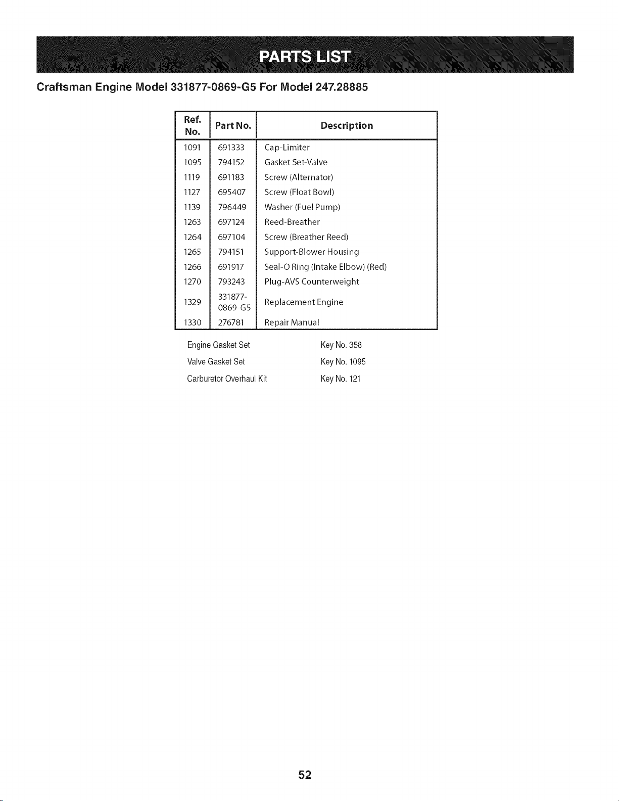
Craftsman Engine Model 331877=0869=G5 For Model 247.28885
Ref,
No,
1091 691333
1095 794152
1119 691183
1127 695407
1139 796449
1263 697124
1264 697104
1265 794151
1266 691917
1270 793243
331877-
1329
0869-G5
1330 276781
I Part No. Description
Cap-Limiter
Gasket Set-Valve
Screw (Alternator)
Screw (Float Bowl)
Washer (Fuel Pump)
Reed-Breather
Screw (Breather Reed)
Support-Blower Housing
Seal-O Ring (Intake Elbow) (Red)
Plug-AVS Counterweight
Replacement Engine
Repair Manual
EngineGasketSet
ValveGasketSet
CarburetorOverhaulKit
Key No.358
Key No.1095
Key No.121
52
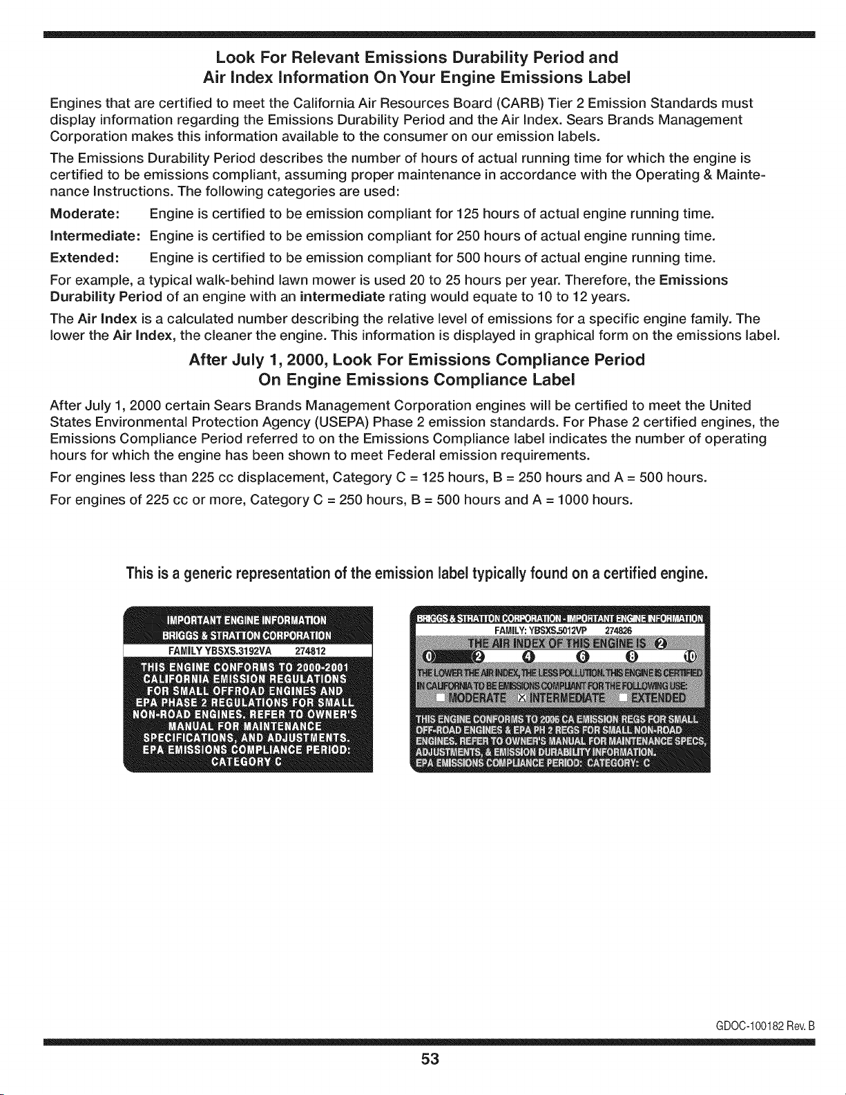
Look For Relevant Emissions Durability Period and
Air index information On Your Engine Emissions Label
Engines that are certified to meet the California Air Resources Board (CARB) Tier 2 Emission Standards must
display information regarding the Emissions Durability Period and the Air Index. Sears Brands Management
Corporation makes this information available to the consumer on our emission labels.
The Emissions Durability Period describes the number of hours of actual running time for which the engine is
certified to be emissions compliant, assuming proper maintenance in accordance with the Operating & Mainte-
nance Instructions. The following categories are used:
Moderate: Engine is certified to be emission compliant for 125 hours of actual engine running time.
Intermediate: Engine is certified to be emission compliant for 250 hours of actual engine running time.
Extended: Engine is certified to be emission compliant for 500 hours of actual engine running time.
For example, a typical walk-behind lawn mower is used 20 to 25 hours per year. Therefore, the Emissions
Durability Period of an engine with an intermediate rating would equate to 10 to 12 years.
The Air index is a calculated number describing the relative level of emissions for a specific engine family. The
lower the Air Index, the cleaner the engine. This information is displayed in graphical form on the emissions label.
After July 1,2000, Look For Emissions Compliance Period
On Engine Emissions Compliance Label
After July 1, 2000 certain Sears Brands Management Corporation engines will be certified to meet the United
States Environmental Protection Agency (USEPA) Phase 2 emission standards. For Phase 2 certified engines, the
Emissions Compliance Period referred to on the Emissions Compliance label indicates the number of operating
hours for which the engine has been shown to meet Federal emission requirements.
For engines less than 225 cc displacement, Category C = 125 hours, B = 250 hours and A = 500 hours.
For engines of 225 cc or more, Category C = 250 hours, B = 500 hours and A = 1000 hours.
This is a generic representation of the emission label typically found on a certified engine.
FAMILYYBSXS.3192VA 274812
GDOC-100182Rev.B
53
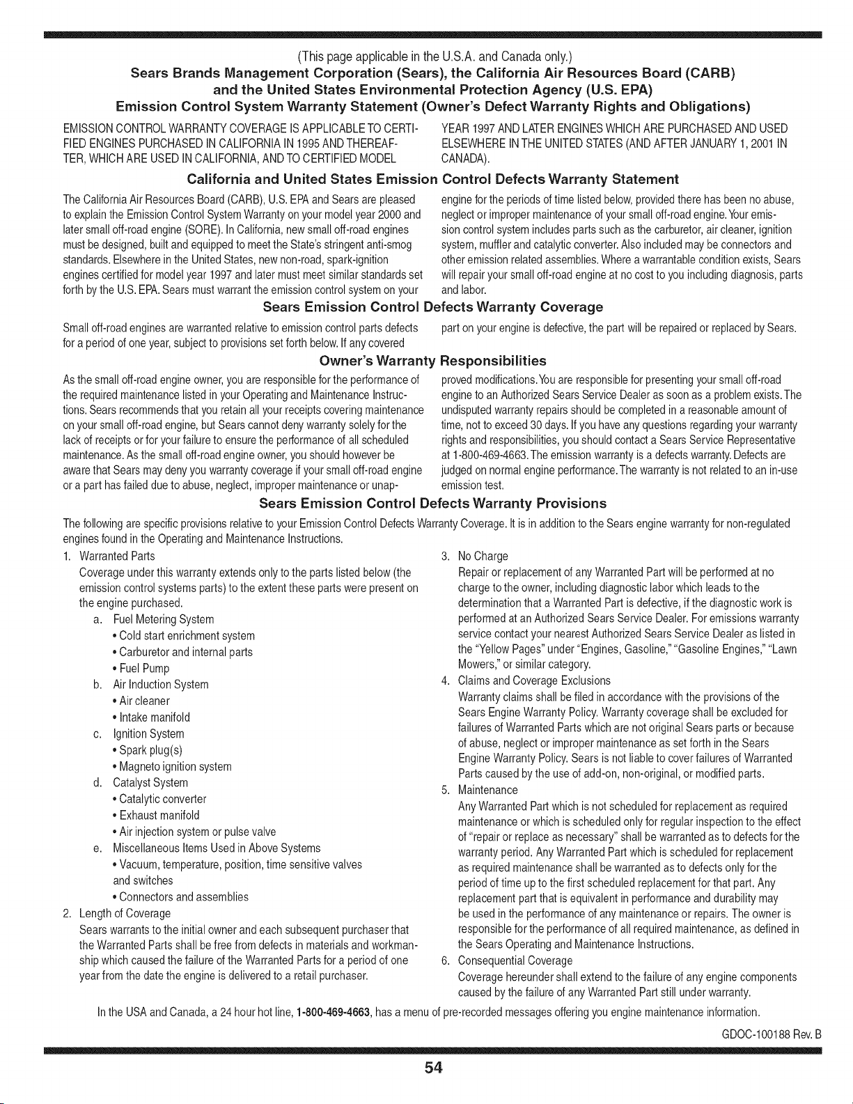
(Thispageapplicablein the U.S.A.and Canadaonly.)
Sears Brands Management Corporation (Sears), the California Air Resources Board (CARD)
and the United States Environmental Protection Agency (U.S. EPA)
Emission Control System Warranty Statement (Owner's Defect Warranty Rights and Obligations)
EMISSIONCONTROLWARRANTYCOVERAGEISAPPLICABLETO CERTI-
FIEDENGINESPURCHASEDIN CALIFORNIAIN 1995ANDTHEREAF-
TER,WHICHARE USEDINCALIFORNIA,ANDTOCERTIFIEDMODEL
California and United States Emission
The CaliforniaAir ResourcesBoard(CARD),U.S.EPAand Searsare pleased
to explainthe EmissionControlSystemWarrantyonyour modelyear2000and
latersmalloff-roadengine(SORE).InCalifornia,newsmall off-roadengines
mustbe designed,builtand equippedto meettheState'sstringentanti-smog
standards.Elsewherein theUnitedStates, newnon-road,spark-ignition
enginescertifiedfor modelyear 1997and latermustmeetsimilarstandardsset
forth bythe U.S.EPA.Sears mustwarrantthe emissioncontrol systemon your
YEAR 1997AND LATERENGINESWHICHARE PURCHASEDAND USED
ELSEWHEREIN THE UNITEDSTATES(ANDAFTERJANUARY1,2001 IN
CANADA).
Control Defects Warranty Statement
enginefor theperiodsoftime listedbelow,providedtherehas been noabuse,
neglector impropermaintenanceof your smalloff-roadengine.Youremis-
sion controlsystemincludespartssuch as thecarburetor,air cleaner,ignition
system,mufflerand catalyticconverter.Also includedmay be connectorsand
otheremissionrelatedassemblies.Wherea warrantableconditionexists,Sears
will repairyour smalloff-roadengineat no costto you includingdiagnosis,parts
and labor.
Sears Emission Control Defects Warranty Coverage
Smalloff-roadenginesarewarrantedrelativeto emissioncontrol partsdefects
fora periodof one year,subjectto provisionsset forth below.Ifany covered
Owner's Warranty
Asthe smalloff-roadengine owner,you are responsiblefor the performanceof
therequiredmaintenancelistedin yourOperatingand MaintenanceInstruc-
tions.Searsrecommendsthatyou retainall yourreceiptscoveringmaintenance
on yoursmalloff-roadengine,but Sears cannotdenywarrantysolelyfor the
lackof receiptsorfor yourfailureto ensurethe performanceof all scheduled
maintenance.As the smalloff-roadengineowner,you shouldhoweverbe
awarethat Searsmaydenyyou warrantycoverageif your smalloff-roadengine
ora part hasfailed dueto abuse,neglect,impropermaintenanceor unap-
parton yourengineis defective,the part willbe repairedor replacedbySears.
Responsibilities
provedmodifications.Youare responsiblefor presentingyour smalloff-road
engineto an AuthorizedSearsServiceDealeras soonas a problemexists.The
undisputedwarrantyrepairsshouldbe completedin a reasonableamountof
time,not to exceed30 days. Ifyou haveany questionsregardingyourwarranty
rightsand responsibilities,youshouldcontacta SearsService Representative
at 1-800-469-4663.The emissionwarrantyis a defectswarranty.Defectsare
judgedon normalengineperformance.Thewarrantyis notrelatedto an in-use
emissiontest.
Sears Emission Control Defects Warranty Provisions
ThefollowingarespecificprovisionsrelativetoyourEmissionControlDefectsWarrantyCoverage.ItisinadditiontotheSearsenginewarrantyfornon-regulated
enginesfound in the Operatingand MaintenanceInstructions.
1. WarrantedParts
Coverageunderthis warrantyextendsonly to the parts listedbelow (the
emissioncontrolsystemsparts)to the extentthese partswere presenton
the engine purchased.
a. FuelMeteringSystem
• Cold start enrichmentsystem
• Carburetorand internalparts
• FuelPump
b. Air lnduction System
• Air cleaner
• Intakemanifold
c. IgnitionSystem
• Spark plug(s)
• Magnetoignitionsystem
d. CatalystSystem
• Catalyticconverter
• Exhaustmanifold
• Air injectionsystemor pulsevalve
e. MiscellaneousItemsUsedin AboveSystems
• Vacuum,temperature,position,timesensitivevalves
andswitches
• Connectorsandassemblies
2. Lengthof Coverage
Searswarrantsto the initialownerand eachsubsequentpurchaserthat
the WarrantedParts shallbe free from defects in materialsandworkman-
shipwhich causedthefailure of the WarrantedPartsfor a period of one
yearfromthe datethe engineis deliveredto a retailpurchaser.
3. NoCharge
Repairor replacementof anyWarrantedPartwill be performedat no
chargeto the owner,includingdiagnosticlabor whichleads to the
determinationthata WarrantedPartis defective,if the diagnosticwork is
performedat an AuthorizedSears ServiceDealer.For emissionswarranty
servicecontact yournearestAuthorizedSears ServiceDealeras listed in
the "YellowPages"under"Engines,Gasoline,""GasolineEngines,""Lawn
Mowers,"or similar category.
4. Claimsand CoverageExclusions
Warrantyclaimsshall be filed in accordancewiththe provisionsof the
Sears EngineWarrantyPolicy.Warrantycoverageshall be excludedfor
failuresof WarrantedPartswhichare not original Sears partsor because
of abuse, neglector impropermaintenanceas setforth inthe Sears
EngineWarrantyPolicy.Sears is not liableto coverfailuresof Warranted
Partscausedby theuse of add-on,non-original,or modifiedparts.
5. Maintenance
Any WarrantedPart whichis notscheduledfor replacementas required
maintenanceor whichis scheduledonly for regularinspectionto the effect
of "repairor replaceas necessary"shallbe warrantedasto defectsfor the
warrantyperiod.Any WarrantedPartwhich is scheduledfor replacement
as requiredmaintenanceshallbe warrantedasto defectsonly forthe
periodof time upto the firstscheduledreplacementfor that part. Any
replacementpart that is equivalentin performanceand durabilitymay
be usedin the performanceof any maintenanceor repairs.The owneris
responsibleforthe performanceof all requiredmaintenance,as definedin
the SearsOperatingand MaintenanceInstructions.
6. ConsequentialCoverage
Coveragehereundershallextend to the failure of any engine components
caused bythe failureof any WarrantedPartstill underwarranty.
Inthe USAandCanada,a 24 hourhot line, 1-800-469-4663,hasa menu of pre-recordedmessagesofferingyou enginemaintenanceinformation.
GD0C-100188Rev.B
54
FEDERAL and/or CALIFORNIA EMISSION CONTROL WARRANTY STATEMENT
YOUR WARRANTY RIGHTS AND OBLIGATIONS
MTDConsumerGroupInc,the UnitedStatesEnvironmentalProtectionAgency (EPA),and, forthose productscertifiedfor sale in the stateof California,the
CaliforniaAir ResourcesBoard(CARB)are pleasedto explainthe emission(evaporativeand/or exhaust)controlsystem(ECS) warrantyonyouroutdoor 2006
andlater smalloff-roadspark-ignitedengine andequipment(outdoorequipmentengine)In California,new outdoorequipmentengines mustbe designed,built and
equippedto meetthe State'sstringentanti-smog standards(in otherstates, 1997andlater modelyear equipmentmustbe designed,built, and equippedto meet
theU.S. EPAsmalloff-road, sparkignitionengineregulations.MTDConsumerGroupInc mustwarrantthe ECSon your outdoorequipmentenginefor the periodof
timelisted belowprovidedtherehas been no abuse, neglector impropermaintenanceof outdoor equipmentengine.
Your ECSmay includeparts such as thecarburetor,fuel-injectionsystem,the ignitionsystem,catalyticconverter,fuel tanks,fuel lines,fuelcaps, valves,canisters,
filters,vapor hoses,clamps,connectors,andotherassociatedemission-relatedcomponents.
Wherea warrantableconditionexists, MTDConsumerGroupIncwill repairyouroutdoorequipmentengineat no cost to you includingdiagnosis,parts and labor.
MAN UFACTURER'S WARRANTY COVERAGE:
Thisemissioncontrolsystemis warrantedfor two years. If any emission-relatedpart on your outdoorequipmentengine is defective,the part will be repairedor
replacedby MTDCONSUMERGROUPINC.
OWNER'S WARRANTY RESPONSIBILITIES:
Asthe outdoorequipmentengineowner,you are responsiblefor performanceof the requiredmaintenancelisted inyour owner'smanual.MTDConsumerGroup
Inc recommendsthat you retain all receiptscoveringmaintenanceon youroutdoor equipmentengine,but MTDConsumerGroupInc cannotdeny warrantysolely
forthe lackof receipts.
Asthe outdoorequipmentengineowner,you shouldhoweverbe awarethat MTDConsumerGroupInc may denyyou warrantycoverageif your outdoorequipment
engineor a part has faileddue to abuse, neglect,or impropermaintenanceor unapprovedmodifications.
Youare responsiblefor presentingyouroutdoor equipmentengineto MTDConsumerGroupInc'sdistributioncenteror servicecenteras soon asthe problem
exists.The warrantyrepairsshouldbe completedin a reasonableamountof time, not to exceed30 days.If you havea questionregardingyour warrantycoverage,
you shouldcontactthe MTDConsumerGroupIncService Departmentat 1-800-800-7310orvia emailat http://support.mtdproducts.com
GENERAL EMISSIONS WARRANTY COVERAGE:
MTDConsumerGroupIncwarrantsto the ultimatepurchaserand eachsubsequentpurchaserthat the outdoorequipmentengineis: Designed,built and equipped
so asto conformwith all applicableregulations;and freefromdefects in materialsand workmanshipthatcausethe failureof a warrantedpart to be identicalin all
materialrespectsto that part as describedin MTDConsumerGroup Inc'sapplicationfor certification.
The warrantyperiodbeginson the date the outdoor equipmentengineis deliveredto anultimate purchaseror first placedintoservice.The warrantyperiodis two
years.
Subjectto certain conditionsand exclusionsasstated below,the warrantyon emission-relatedparts is asfollows:
1. Any warrantedpart that is not scheduledfor replacementas requiredmaintenancein the written instructionssupplied, is warrantedforthe warrantyperiod
statedabove. Ifthe part fails duringthe periodof warrantycoverage,thepart will be repairedor replacedbyMTDConsumerGroupInc accordingto subsection
(4) below. Anysuchpart repairedor replacedunderwarrantywillbe warrantedfor the remainderof the period.
2. Any warrantedpart that is scheduledonly for regularinspectionin the writteninstructionssuppliedis warrantedforthe warrantyperiod statedabove.Any such
part repairedor replacedunderwarrantywill be warrantedforthe remainingwarrantyperiod.
3. Any warrantedpart that is scheduledfor replacementas requiredmaintenancein the written instructionssuppliedis warrantedfor the periodof time beforethe
first scheduledreplacementdatefor that part. If the partfails beforethefirst scheduledreplacement,the part will berepairedor replacedby MTDConsumer
GroupInc accordingto subsection(4) below.Any such part repairedor replacedunderwarrantywill be warrantedfor the remainderof the periodprior to the
first scheduledreplacementpointfor the part.
4. Repairor replacementof any warrantedpart underthe warrantyprovisionshereinmustbe performedat a warrantystationat no chargeto the owner.
5. Notwithstandingthe provisionsherein,warrantyservicesor repairswill be providedat all of our distributioncentersthatare franchisedto servicethe subject
enginesor equipment.
6. The outdoorequipmentengine ownerwill not be chargedfor diagnosticlaborthat is directlyassociatedwithdiagnosisof a defective,emission-relatedwar-
rantedpart, providedthat suchdiagnosticworkis performedat a warrantystation.
7. MTDConsumerGroupInc is liablefor damagesto otherengine or equipmentcomponentsproximatelycausedby a failure underwarrantyof any warranted
part.
8. Throughoutthe off-roadengineand equipmentwarrantyperiodstatedabove,MTDConsumerGroup Inc will maintaina supply of warrantedparts sufficientto
meetthe expecteddemandfor such parts.
9. Any replacementpart maybe usedin the performanceof any warrantymaintenanceor repairsand mustbe providedwithoutchargeto the owner.Suchuse will
notreducethe warrantyobligationsof MTDConsumerGroupInc.
10.Add-onor modifiedpartsthat are notexemptedbythe Air ResourcesBoardmaynot beused.The use of any non-exemptedadd-on or modifiedparts by the
ultimatepurchaserwill begroundsfor disallowinga warrantyclaims.MTDConsumerGroup Incwill notbe liableto warrantfailuresof warrantedparts caused
bythe use of a non-exemptedadd-onor modifiedpart.
WARRANTED PARTS:
The repairor replacementof any warrantedpart otherwiseeligiblefor warrantycoveragemaybe excludedfrom such warrantycoverageif MTDConsumerGroup
Inc demonstratesthatthe outdoor equipmentenginehas beenabused,neglected,orimproperlymaintained,and thatsuch abuse, neglect,or impropermainte-
nancewasthe direct causeof the needfor repairor replacementof the part.That notwithstanding,anyadjustmentof a componentthat hasa factory installed,
andproperlyoperating,adjustmentlimitingdevice is still eligible for warrantycoverage.Further,the coverageunderthis warrantyextendsonly to partsthat were
presentonthe off-roadengineand equipmentpurchased.
Thefollowing emissionwarrantypartsare covered(if applicable):
(1) FuelMeteringSystem
• Cold start enrichmentsystem(softchoke)
• Carburetorand internalparts (or fuel injectionsystem)
• Fuelpump
• Fueltank
(2) Air InductionSystem
• Air cleaner
• Intakemanifold
(3) IgnitionSystem
• Spark plug(s)
• Magnetoignitionsystem
(4) ExhaustSystem
• Catalyticconverter
• SAI (Reed valve)
(5) MiscellaneousItemsUsedin AboveSystem
• Vacuum,temperature,position,timesensitivevalvesand switches
• Connectorsandassemblies
(6) EvaporativeControl
• Fuelhose
• Fuelhoseclamps
• Tetheredfuel cap
• Carboncanister
• Vapor lines
GDOC-100223Rev.A
Congratulationson makinga smartpurchase.YournewCraftsman@
productis designedand manufacturedfor yearsof dependableopera-
tion.But likeall products,it mayrequirerepairfrom time to time.That's
whenhavinga RepairProtectionAgreementcansaveyoumoneyand
aggravation.
Here'swhatthe RepairProtectionAgreement*includes:
* Expert service byour 10,000professionalrepairspecialists
o Unlimitedserviceand no chargefor partsand laboron all
coveredrepairs
o Product replacementupto $1500if yourcoveredproductcan't be
fixed
• Discountof 10%from regularprice of serviceand relatedinstalled
partsnotcoveredby theagreement;also, 10%off regularpriceof
preventivemaintenancecheck
• Fast help by phone- we call it RapidResolution- phonesupport
froma Searsrepresentative.Thinkof usas a "talkingowner's
manual."
Onceyou purchasethe Agreement,a simplephonecall is all thatit
takesfor youto scheduleservice.Youcan call anytimedayor night,or
schedulea serviceappointmentonline.
The RepairProtectionAgreementis a risk-freepurchase.If youcancel
for any reasonduringthe productwarrantyperiod,wewill provideafull
refund.Or,a proratedrefundanytimeafterthe productwarrantyperiod
expires.Purchaseyour RepairProtectionAgreementtoday!
Somelimitationsand exclusionsapply. For pricesand additional
informationin the U.S.A. call 1-800-827-6655.
*Coverage in Canadavaries on some items. Forfull details call
Sears Canadaat 1-800-361-6665.
Sears Installation Service
ForSearsprofessionalinstallationof homeappliances,garagedoor
openers,waterheaters,and othermajorhomeitems,in the U.S.A.or
Canadacall 1-800-4-MY-HOME®.
57
Operaci6n segura Practicas .......... Paginas 59 Fuera de temporada de almacenamiento .. Page 85
Etiquetas De Seguridad ................ Page 65 Solucion de problemas ................ Page 86
Asamblea ........................... Page 66 Lista de piezas ..................... Paginas 30
Operacion de ...................... Paginas 68 Reparaci6n de Acuerdo de Proteccion .... Page 91
De Servicio y Mantenimiento de ....... Paginas 75 Servicio de nOmeros ............ atrasados Page
ARTESANO DE DOS AI_IOS DE GARANT{A
PORDOSANOSa partirde la fechade compra,si alguna parteno fungiblesde este equipode equitaci6nfalla debidoa undefectode material
o manode obra,www.craftsman.com visiteo Ilamea 1-800-659-5917paraorganizarde formagratuitaen reparaci6ndeviviendas.
Elmarcoy eleje delanterose reparar_deformagratuitadurantecincoa_osa partirdela fechade comprapordefectosen materialo manode
obra.
Entodos loscasos, si la reparaci6nresultaimposible,elequipode montara caballoser_.sustituidodeformagratuitacon el mismoo equiva-
lente.
Labateriase sustituyedeformagratuitadurante90 dias a partirde la fechade comprapor defectosen materialo manode obra (nuestras
pruebasdemuestraqueno mantienelacarga).
Estagarantiaes inv_Jidasi este productose utilizaal mismotiempo la prestaci6nde servicioscomercialeso si sealquila a otrapersona.
Estagarantia cubrelos defectos SOLOde materiales yfabricaci6n. Lagarantia noincluye:
• Aquellaspiezasfungiblesque puedengastarsepor el uso normaldentrodelperiodode garantia,incluyendoperono limitadoa, cuchillas,
bujias,filtrosde aire,correasy filtrosde aceite.
• Losserviciosde mantenimiento,cambiosdeaceite,o puestasa punto.
• Tireel reemplazoo reparaci6nde pinchazoscausadosporobjetosexternos,talescomoclavos,espinas,toconeso vidrio.
• Tirede la ruedao el reemplazoo la reparaci6nresultantesdel desgastenormal,accidenteo realfuncionamientoo mantenimiento.
• Las reparacionesnecesariasdebidoal abusodeloperador,incluyendoperono limitadoa los da_oscausadosporel remolquede los
objetosm_sall_de la capacidaddel equipode equitaci6n,el impactode objetosque doblenla estructuraoel cig(Je_al,ode excesode
velocidaddelmotor.
• Las reparacionesnecesariasdebidoa la negligenciadel operador,incluyendoperonolimitadoa, da_osel_ctricosy mec_nicoscausados
porunalmacenamientoinadecuado,no utilizaci6nde la calidado cantidadde aceitede motor,no mantenerel piso librede residuos
inflamables,o falta de mantenimientodel Equipoecuestrede acuerdoa lasinstruccionescontenidasen el manualdel operador.
• El motor(sistemade combustible)de limpiezao reparacionesprovocadasporuncombustiblequese contaminadou oxidado(viejo). En
general,el combustibledebeser utilizadodentrode los30 dias siguientesa lafecha de compra.
• Deterioroy desgastenormalde los acabadosexteriores,o reemplazode la etiquetadel producto.
Estagarantialeotorgaderechoslegalesespecificos,y ustedtambi_npuede tenerotros derechosquevariande estadoa estado.
Sears Brands CorporationGesti6n,HoffmanEstates, IL 60179
Aceitedel motor: SAE30
Combustible: Gasolinasinplomo
Bujia: Champion®RC12YC
Motor: Briggs& Stratton
N_mero de modelo ..........................................................
N_mero de serie ..............................................................
Fechade compra .............................................................
Registrearribael nOmerodel modelo,el nOmerode seriey la fecha
de compra
© Sears Brands,LLC
58
Lapresenciadeeste sirnboloindicaque setrata de instrucciones
irnportantesde seguridadquese deben respetarpara evitar
poneren peligrosu seguridadpersonaly/o materialy lade otras
personas.Lea y siga todaslas instruccionesdeestemanualantes
de poneren funcionarnientoestarn_.quina.Si no respetaestas
instruccionespodriaprovocarlesionespersonales.Cuandoveaeste
sirnbolo,ipresteatenci6na la advertencia!
PROPOSICION 65 DE CALIFORNIA
Elescapedel motordeeste producto,algunosde suscornponentes
y algunoscornponentesdelvehiculocontieneno liberansustancias
quirnicasqueel estado de Californiaconsideraque puedenproducir
c_.ncer,defectosde nacirnientou otros problernasreproductivos.
Losbornesdela bateriay los accesoriosalinescontienenplornoy
cornpuestosde plorno,sustanciasquirnicasque segOnIo estableci-
do pot el Estadode Californiacausanc_.ncery da_osenel sisterna
reproductivo.Ldveselas manos despu_sde estar en contacto
con estoscomponentes.
Estarn_.quinarueconstruidaparaseroperadadeacuerdocon
las reglasde seguridadcontenidasen este manual.AI igualque
concualquiertipo de equipo rnotorizado,undescuidoo error por
partedeloperadorpuedeproducirlesionesgraves.Esta rn_.quina
es capazde arnputarrnanosy piesy de arrojarobjetoscon gran
fuerza.Deno respetarlas instruccionesde seguridadsiguientesse
puedenproducirlesionesgraveso la rnuerte.
Su responsabilidad--Restrinja el usode estarn_.quina
rnotorizadaa las personasque lean,cornprendany respetenlas
advertenciase instruccionesqueaparecenen estemanualy en la
rn_.quina.
iGUARDEESTASINSTRUCCIONES!
FUNCIONAIVIIENTO GENERAL
• Lea,entienday curnplatodas las instruccionesincluidasen
la rn_.quinay en los rnanualesantesdernontarlay utilizarla.
Guardeestemanualen un lugarseguroparaconsultasfuturasy
peri6dicas,asi cornoparasolicitarrepuestos.
• Farniliaricesecontodoslos controlesy con el usoadecuado
delos rnisrnos.Sepa c6rnodetenerla rn_.quinay desactivarlos
controlesr_.pidarnente.
• No perrnitanuncaque los ni_osrnenoresde 14a_osutilicen
estarn_.quina.Los ni_osde 14a_osen adelantedebenleery
entenderlas instruccionesde operaci6ny norrnasde seguridad
contenidaseneste manual,yen la rn_.quinay debenser
entrenadosy supervisadospor unadulto.
• Nuncaperrnitaquelos adultosoperenesta rn_.quinasin recibir
antesla instrucci6napropiada.
• Paraayudaraevitarel contactocon las cuchillaso unalesi6npor
algOnobjetoquesea arrojado,rnantengaa los observadores,a
los ayudantes,ni_osy rnascotasalejadosal rnenos25 metrosde
la rn_.quinarnientrasest,. en funcionarniento.Detengala rn_.quina
si alguienentraen la zona.
• Inspeccionerninuciosarnenteel Areadondeutilizar_,el equipo.
Retiretodaslas piedras,palos,cables,huesos,juguetesy otros
objetosextra_osque podrianser recogidosy arrojadospor la
acci6nde las cuchillas.Losobjetosarrojadospor la rn_.quina
puedenproducirlesionesgraves.
• Planifiqueel patr6nde cortedelc_spedque hade seguirpara
evitarla descargade materialhacialoscarninos,las veredas,los
observadores,etc.Eviteadern_.sdescargarmaterialcontralas
paredesy obstruccionesquepodrianprovocarqueel material
descargadorebotecontrael operador.
• Paraprotegerselos ojos utilicesiernpreanteojoso antiparras
deseguridadrnientrasoperala rn_.quinao rnientraslaajusta
o repara.Losobjetosarrojadosque rebotanpuedenproducir
lesionesocularesgraves.
• Utilicezapatosde trabajoresistentes,de suelafuerte,asi corno
pantalonesy carnisasajustados.Las prendassueltaso las
alhajaspuedenquedaratrapadasen las piezasrnovibles.Nunca
operela rn_.quinadescalzoo con sandalias.
• Est_atentoa la cortadoray a la direcci6nde la descargade
losaditarnentosy noapuntea nadie.Nuncaoperelacortadora
de c_spedsin que est_nen su lugarapropiadolacubiertade
descargao elcolectorde recortesde cesped.
• Noponga lasrnanoso lospies cercade las piezasrotatoriaso
debajode la plataforrnadecorte. Elcontactocon las cuchillas
puedeproducirla arnputaci6nde rnanosy pies.
• Unacubiertade descargafaltanteo da_adapuedeprovocarel
contactocon la cuchillao lesionespor objetosarrojados.
• Detengala(s)cuchilla(s)cuandoatraviesesenderos,sendaso
carninosdegravay cuandono est_cortandoel cesped.
• Vigileel tr_.nsitovehicularcuandoest_operandocercadeo en
crucesde carninos.Estarn_.quinano debeutilizarseen la via
pOblica.
• Noopereestarn_.quinabajolosefectosdelalcoholode drogas.
• Corteel cespedsolarnentecon luzdedia o con unabuenaluz
artificial.
• Nuncatransportepasajeros.
• Desenganchela(s)cuchilla(s)antesdecolocarla rnarchaatr_.s.
Retrocedalentarnente.Siernpremirehaciaabajoy haciaatr_.santes
y rnientrasretrocede,paraevitaraccidentes.
• Reduzcalavelocidadantesdedar la vuelta.Operela rn_.quina
suavernente.Evitela operaci6nerr_.ticay la velocidadexcesiva.
• Desenganchela(s)cuchilla(s),coloqueel frenodeestaciona-
rniento,detengael motory esperehastaque la(s)cuchilla(s)se
detenga(n)porcornpletoantesde retirarel colectorde c_sped,
vaciarlos recortes,destaparel canal,retirarrestosde cespedo
desechos,o hacercualquierajuste.
59
• Nuncadejelarn_.quinaen funcionarnientosinvigilancia.Apague
siernprelascuchillas,coloqueelfrenodernano,detengaelmotory
retirela Ilaveantesdebajarsedelvehiculo.
• Tengasurnocuidadoal cargaro descargarla rn_.quinaen un
rernolqueocarni6n.Estaunidadnodebeconducirseenascensoo
descensoderarnpas,porquepodrialadearsey provocarlesiones
personalesgraves.Enlas rarnpaslarn_.quinasedebe ernpujar
rnanualrnenteparacargarlao descargarlacorrectarnente.
• Elsilenciadory el motorse calientany puedencausarquernaduras.
Nolos toque.
• Reviseel espaciolibrepot encirnade lacabezaantesdeconducir
bajolas rarnasbajasde _.rboles,cables,cerrarnientosde puertas,
etc.enloscualeseloperadorpodriaatorarseo serernpujadofuera
dela rn_.quina,Ioquepodriaresultaren lesionesgraves.
• Desenganchetodoslosernbraguesdelos accesoriosy presione
totalrnenteel pedaldel frenoantesdeintentararrancarel motor.
• Larn_.quinaest,.diseSadaparacortarc_spedresidencialnormal,
conunaalturano mayora 10".Nointentecortarcespeddernasiado
crecido,seco(porej.,pastura)nipilasdehojassecas.Elc_sped
y las hojassecaspuedenentraren contactoconel escapedel
motory/o acurnularseenla plataforrnade lacortadoradecesped,
convirti_ndoseen unpeligrode incendio
• Utilicesolarnenteaccesoriosy aditarnentosaprobadosparaesta
rn_.quinapot elfabricantedela misrna.Lea,cornprenday siga
todaslas instruccionesproporcionadasconlosaccesorioso
aditarnentosaprobados.Paraobteneruna listade losaccesorios
aprobadosy losarchivosadjuntos,Ilarne1-800-659-5917.
• Losdatosestadfsticosrnuestranque losoperadoresde60 aSos
y rnayoresseven involucradosenun altoporcentajede lesiones
relacionadascontractorescorta cesped.Estosoperadoresdeben
evaluarsu capacidadparaoperarel tractorcortac_speden forrna
suficienternentesegurapara protegersea ellosrnisrnosy a los
dern_.scontralesionesgraves.
Si se presentansituacionesque no est_.nprevistasen este
manualseacuidadosoy use el sentidocornQn.Contacto1-800-
659-5917parainforrnaci6ny asistencia.
FUNCIONAiVIIENTO EN PENDIENTES
Las pendientesson unfactorirnportanterelacionadoconaccidentes
porderrapey vuelcosque puedenproducirlesionesgravese incluso
la rnuerte.Laoperaci6nen pendientesrequieremayorprecauci6n.
Si nopuederetrocederen la pendienteo si no se sienteseguro,no
realiceningunaoperaci6ndecorte.
Parasu seguridad,use el indicadordependientesquese incluye
cornopartede estemanualpara rnedirla pendienteantesde operarla
rn_.quinaen una zonainclinada.Sila pendientees mayorde 15 grados
segQnel rnedidor,noopereestarn_.quinaen ese sector,puespodria
causarlesionesgraves.
HagaIo siguiente:
• Podehaciaarribay abajode las pendientes,nodeforrnatrans-
versal.Tengacuidadocuandocarnbiededirecci6nal operaren
pendiente.
• Est_atentoa loshoyos,surcos,baches,rocas,uotrosobjetos
ocultos.Elterrenodesniveladopuedevoltearla rn_.quina.Elcesped
altopuedeocultarobst_.culos.
• Vayaa bajavelocidad.ElijaunavelocidadIosuficienternentebaja,
de rnodoquenotengaque detenerseo hacercarnbiosrnientras
est,.sobrela pendiente.Losneurn_.ticospodrianperdertracci6n
sobrelaspendientesa[3ncuandolosfrenosfuncionaranapro-
piadarnente.Siernprernantengala rn_.quinaencarnbiornientras
desciendelaspendientes,parapoderfrenarconel motor.
• Sigalas recornendacionesdel fabricanteparalos pesoso contra-
pesosdelas ruedas,pararnejorarlaestabilidaddelarn_.quina.
Pararecornendaciones,Ilarneal 1-800-659-5917.
• Tengaespecialcuidadocon loscolectoresdec_spedu otros
aditarnentos.Losrnisrnospuedenrnodificarla estabilidadde la
rn_.quina.
• Hagaquetodos losrnovirnientosen laspendientesseanlentosy
graduales.Nocarnbierepentinarnentela velocidadnila direcci6n.
Unfrenadoo carnbiode velocidadrepentinospuedencausarque
el frentede larn_.quinase levantey d_unavolteretahaciaatr_.s,Io
quepodriaproducirlesionesgraves.
• Evitearrancaro detenerseenunapendiente.Silosneurn_.ticos
pierdenlatracci6n,desenganchelascuchillasy descienda
lentarnentela pendiente.
No hagaIo siguiente:
• Nogire sobrelaspendientesa rnenosqueseanecesario.Sies
posible,girelentarnentey gradualrnenteduranteeldescenso.
• Nocorteelc_spedcercade pozos,hundirnientoso terraplenes.La
cortadoradec_spedpuedevolcarserepentinarnentesiunade las
ruedasest,.sobreel hordedeunacantilado,zanjao siunhordese
desrnorona.
• Nointenteestabilizarlarn_.quinaponiendoelpieenel suelo.
• Noutiliceuncolectordec_speden pendientesernpinadas.
• Nopodeel c_spedhQrnedo.Unarnenortracci6npodriacausar
derrapes.
• Noparadescender.El excesode velocidadpuedehacerqueel
operadorpierdaelcontroldelarn_.quina,ocasionandolesiones
graveseinclusolarnuerte.
• Norernolquecargaspesadasdetr_.sdelosaditarnentos(carritode
basuracargado,podadorade rodillos,etc)en pendientesrnayores
de5 grados.Cuandosedesplazapendienteabajo,el pesoadicional
tiendea ernpujarel tractory puedehacerquese pierdael control
delrnisrno(porejernplo,eltractorsepuedeacelerar,se reducela
capacidadparafrenary rnaniobrar,losaccesoriospuedenplegarse
cornouncortaplurnasy hacerqueel tractorvuelque).
NINOS
Puedenocurriraccidentestr_.gicossi el operadornoest,.atentoa la
presenciade niSos.PotIo general,los niSosse sientenatraidospor
estetipo de rn_.quinasy su funcionarniento.Noentiendenlos riesgos
ni los peligros.Nuncaasurnaque los niSosperrnanecer_.nen el rnisrno
lugardonde losvio porQltirnavez.
• Mantengaa losniSosfueradel_.readetrabajoy bajoestricta
vigilanciadeunadultoresponsableadern_.sdel propiooperador.
Est_alertay apaguela rn_.quinasi unniSoingresaal_.rea.
• Antesy rnientrasest,.retrocediendo,mirehaciaatr_.sy cuidequeno
hayaniSos.
NuncatransporteniSos,aQnconla cuchillaapagada.Podriancaerse
y resultarseverarnenteheridoso interferirconlaoperaci6nsegurade
la rn_.quina.
Tengaextrernaprecauci6ncuandoseaproxirnea esquinasciegas,
portales,arbustos,_.rbolesu otrosobjetosquepuedanirnpedirlever
a unniSoquesecruceenel recorridode la rn_.quina.
6O
• Paraevitaraccidentesaloperaren rnarchaatrAs,siernpredesengan-
chelascuchillasantesdecolocarrnarchaatrAs.Siest_instalado,
el"ModoPrecaucidnMarchaAtr_s"(hojasdeoperarlarn_quina,
rnientrasquelospaseosala inversa)nodebeutilizarsecuandohay
ni_osuotraspersonaspresentes.
• Mantengaa losni_osalejadosdelosrnotoresenrnarchao calientes.
Puedensufrirquernadurasconun silenciadorcaliente.
• RetirelaIlavecuandodeje la rn_.quinasinvigilancia,evitequeuna
personasinautorizaci6nla rnaneje.
No perrnitanuncaque los ni_osrnenoresde 14a_osutilicenesta
rn_quina.Losni_osde 14a_osen adelantedebenleer y entenderlas
instruccionesdeoperaci6ny norrnasde seguridadcontenidasen este
manual,yen la rn_quinay debenserentrenadosy supervisadospor
unadulto.
REIVIOLQUE
• RernolqueL_nicarnenteconunarn_quinaquecuenteconun
enganchediseSadopararernolcar.Noacopleequiporernolcado
exceptoenelpuntodeenganche.
• Sigalasrecornendacionesdel fabricanteenIoquerespectaalos
lirnitesdepesodelosequiposa rernolcary alrernolqueenpendien-
tes.Pararecornendaciones,Ilarneal 1-800-659-5917.
• Nuncaperrnitala presenciade niSosuotraspersonasdentroo sobre
losequiposrernolcados.
• En laspendientes,elpesodel equiporernolcadopuedecausar
p_rdidadetraccidny perdidade controlde la rn&quina.
• Siernpreuseextrala precauci6nrernolcandoconunarnaquina
capazdehacervueltasapretadas(p.ejpaseo"devueltacero"-enel
cortacesped).Hagaarnpliasvueltasparaevitaralgato-knifing.
• Desplaceselentarnentey dejedistanciaadicionalparafrenado.
• Noparadescender.
SERVIClO
Manejo seguro de la gasolina
Paraevitarlesionespersonaleso daSosrnaterialessea surnarnente
cuidadosoal rnanipularla gasolina.Lagasolinaes surnarnente
inflarnabley sus vaporespuedencausarexplosiones.Se puede
lesionargravernentesi derrarnagasolinasobreustedo sobrela ropa,
ya que _sta se puedeincendiar.L&vesela piely c&rnbiesede ropade
inrnediato.
• Utilices61olosrecipientesparagasolinaautorizados.
• NuncaIlenelos recipientesenel interiorde unvehiculoo carni6n
o cajade rernolquecon recubrirnientopl&stico.Coloquesiernpre
losrecipientesenel piso y lejosdel vehiculoantesde realizarla
carga.
• Cuandoseafactible,retireel equipoa gasolinadel carni6no
rernolquey II_neloen elsuelo.Si esto no es posible,Ileneel
equipoen unrernolqueconun contenedorport&til,envezde
hacerlocon una boquilladispensadorade gasolina.
• Mantengala boquillade Ilenadoencontactoconel hordedel
dep6sitode combustibleocon la aberturadel recipienteen todo
rnornento,hastaterrninarlacarga. 1/outiliceun dispositivode
boquilladeapertura/cierre.
• Apaguetodosloscigarrillos,cigarros,pipasy otrasfuentesde
cornbusti6n.
• Nuncacarguecombustibleenla rn&quinaenun espaciocerrado.
• Nuncasaquela tapadel cornbustibleniagreguecombustible
rnientrasel motorest&calienteo enrnarcha.Dejequeel motor
seenfrie por Iornenosdos rninutosantesde volvera cargar
combustible.
• Nuncalleneen excesoel dep6sitode combustible.Lleneel
tanquenorn&sde 1/2pulgadapordebajode labasedel cuello
del tap6ndecarga, paradejar espaciopara laexpansi6ndel
combustible.
• Vuelvaa colocarlatapa de la gasolinay ajL_stelabien.
• Lirnpieel combustiblequese hayaderrarnadosobreel motory el
equipo.Trasladelarn&quinaa otrazona.Espere5 rninutosantes
de encenderel motor.
• Parareducirel riesgode incendio,rnantengala rn&quinalirnpia
de pasto,hojasy de acurnulaci6nde otros residuos.Lirnpielos
derrarnesdeaceiteo combustibley saquetodos losresiduos
ernbebidosde combustible.
• Nuncaguarde la rn&quinao el recipientede combustibleen un
espaciocerradodondehayafuego,chispaso luz piloto,corno
porejernplodecalentadoresdeagua,calefactoresde arnbientes,
hornos,secadoresde ropau otrosaparatosa gas.
• Dejeque larn&quinase enfriecincorninutospor Iornenosantes
de guardarla.
Servicio general
• Nuncaenciendael motoren espacioscerradoso en una zona
con pocaventilaci6n.El escapedel motorcontienernon6xidode
carbono,ungas inodoroy letal.
• Antesdelirnpiar,repararo inspeccionarla rn&quina,cornpruebe
que la(s)cuchilla(s)y todas laspartesen rnovirnientose hayan
detenido.Desconecteel cablede la bujfay p6ngalohaciendo
rnasacontrael motorparaevitarque se enciendaaccidental-
rnente.
• Reviseperi6dicarnenteparaasegurarsequelascuchillasse
detenganpor cornpletoen aproxirnadarnentecinco(5) segundos
despu_sdeaccionarel controlde desenganchede la(s)
cuchilla(s).Si las cuchillasno se detienendentrode este lapso
de tiernpo,su unidaddeber&ser reparadapor su distribuidorde
servicioautorizadoMTD.
• Reviseconfrecuenciael funcionarnientodelsisternadefrenos
ya que est,. sujetoa desgastepor la operaci6nnormal.Ajuste y
efectL_ernantenirnientosegL_nse requiera.
61
• Reviselos pernosdemontajede la(s) cuchilla(s)y del motora
intervalosfrecuentesparaverificarqueest_nbienapretados.
Adem_.s,inspeccionevisualmentela(s) cuchilla(s)en buscade
daSos(por ejemplo,desgasteexcesivo,abolladuras,rajaduras,
etc.). Reemplacela(s)cuchilla(s)Qnicamentecon lascuchillas
defabricantesde equiposoriginales(O.E.M.)listadasen este
manual.Elusode piezasque no cumplencon las especifi-
cacionesdel equipooriginal podriatenercomo resultadoun
rendimientoincorrectoy adem_.sponeren riesgola seguridad.
• Lascuchillasdelas podadorassonmuy afiladas.Envuelvala
cuchillao utiliceguantesy extremelasprecaucionescuando
efectQemantenimiento.
Mantengatodoslos pernos,tuercasy tornillosbienajustados
paraasegurarsede quela m_.quinase encuentraen condiciones
segurasde operaci6n.
• Nuncaaltereel sistemade enclavamientode seguridadni
otrosmecanismosde seguridad.Controleperi6dicamenteque
funcionencorrectamente.
Despu_sde golpearcon algQnobjetoextraSo,detengael motor,
desconecteelcablede la bujfay conecteel motora masa.
Inspeccioneminuciosamentela m_.quinaparaver si est,.daSada.
Repareel daSoantesdearrancary ufilizarla m_.quina.
Nuncatratede hacerajusteso reparacionesa lam&quina
mientrasel motorest&enmarcha.
• Loscomponentesdel colectordec_spedy la cubiertade
descarga,estansujetosa desgastey daSosque podriandejar
expuestaspartesen movimientoo permifirque se arrojenobjetos.
Paraprotegersuseguridad,verifiquefrecuentementetodos los
componentesy reempl_.celosinmediatamentes61ocon piezasde
los fabricantesdel equipooriginal,listadosen este manual.El uso
de piezasque nocumplencon las especificacionesdel equipo
originalpodriatenercomoresultadoun rendimientoincorrectoy
adem_.sponeren riesgola seguridad.
• Nocambielaconfiguraci6ndel reguladordel motorni Ioopere
a sobrevelocidad.El reguladordel motorcontrolala velocidad
m_.ximaseguradefuncionamientodel motor.
• Mantengao reemplacelasefiquetasde seguridade instrucciones
segQnseanecesario.
Respetelas normasreferentesa ladisposici6ncorrectay las
reglamentacionessobregasolina,aceite,etc. para protegerel
medicambiente.
• SegQnla Comisi6ndeSeguridadde Productospara el Consu-
midorde los EstadosUnidos(CPSC)y la Agenciade Protecci6n
Ambientalde los EstadosUnidos(EPA),este productotieneuna
vida Qtilmediade siete(7) aSos,6 270 horasde funcionamiento.
AIfinalizarla vidaOtilmedia,adquieraunam_.quinanuevao haga
inspeccionaranualmente_staSearsporunou otrodistribuidorde
serviciosparacerciorarsede que todos los sistemasmec_.nicos
y de seguridadfuncionancorrectamentey no tienenexcesivo
desgaste.Si noIo hace,puedenproducirseaccidentes,lesiones
o muerte.
NO MODIFIQUE EL MOTOR
Paraevitarlesionesgraveso lamuerte,no modifiqueel motorbajo
ningunacircunstancia.Si cambialaconfiguraci6ndel reguladordel
motorel motorpuededescontrolarsey operara velocidadesinsegu-
ras.Nuncacambielaconfiguraci6ndef_.bricadel reguladordel motor.
AVlSO REFERIDO A EMISIONES
Losmotoresqueest_.ncertificadosy cumplencon las regulaciones
de emisionesfederalesEPAy de CaliforniaparaSORE(Equipos
peque_ostodoterreno)est_.ncertificadosparaoperarcongasolina
comQnsin plomoy puedenincluirlos siguientessistemasde control
de emisiones:Modificaci6nde motor(EM) y catalizadorde tresvias
(TWO)siest_.nequipadosde esa manera.
GUARDACHISPAS
EstamAquinaest,.equipadacon un motorde combusti6ninternay
nodebe ser utilizadaen o cercade unterrenoagrestecubiertopor
bosque,malezaso hierbaexceptosi el sistemade escapedel motor
est,.equipadocon un amortiguadorde chispasque cumplacon las
leyeslocaleso estatalescorrespondientes,encasode haberlas.
Si se utiliza un amortiguadorde chispasel operadorIo debemantener
en condicionesde usoadecuadas.Enel Estadode Californialas
medidasanteriormentemencionadassonexigidasporIcy (Arficulo
4442del C6digode RecursosPOblicosde California).Esposible
queexistanleyessimilaresenotros estados.Lasleyesfederalesse
aplicanenterritoriosfederales.
Puedeconseguirelamortiguadordechispasparael silenciadora
travesdesu distribuidorautorizadode motoreso poni_ndoseen
contactoconel centrode servicioSears.
62
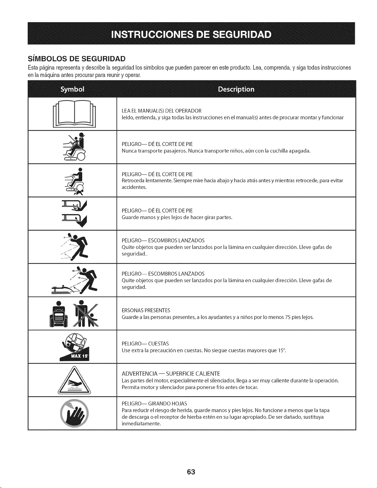
SJlVlBOLOS DE SEGURIDAD
Estap&ginarepresentay describelaseguridadlos simbolosquepuedenpareceren esteproducto.Lea,comprenda,y sigatodasinstrucciones
enla m_quinaantesprocurarpara reuniry operar.
0
AL
LEA EL MANUAL(S) DEL OPERADOR
leido, entienda, y siga todas las instrucciones en el manual(s) antes de procurar montar y funcionar
PELIGRO-- DE EL CORTE DE PIE
Nunca transporte pasajeros. Nunca transporte ni_os, aun con la cuchilla apagada.
PELIGRO-- DE EL CORTE DE PIE
Retroceda lentamente. Siempre mire hacia abajo y hacia atr_is antes y mientras retrocede, para evitar
accidentes.
PELIGRO-- DE EL CORTE DE PIE
Guarde manos y pies lejos de hacer girar partes.
PELIGRO-- ESCOMBROS LANZADOS
Quite objetos que pueden set lanzados pot la I_imina en cualquier direcci6n. Lleve galas de
seguridad..
PELIGRO-- ESCOMBROS LANZADOS
Quite objetos que pueden set lanzados pot la I_imina en cualquier direcci6n. Lleve galas de
seguridad.
ERSONAS PRESENTES
Guarde a las personas presentes, a los ayudantes y a ni_os pot Io menos 75 pies lejos.
PELIGRO-- CUESTAS
Use extra la precauci6n en cuestas. No siegue cuestas mayores que 15°.
ADVERTENCIA -- SUPERFICIE CALIENTE
Las partes del motor, especialmente el silenciador, Ilega a set muy caliente durante la operaci6n.
Permita motor y silenciador para ponerse frio antes de tocar.
PELIGRO-- GIRANDO HOJAS
Para reducir el riesgo de herida, guarde manos y pies lejos. No funcione a menos que la tapa
de descarga o el receptor de hierba est_n en su lugar apropiado. De ser dahado, sustituya
inmediatamente.
63

_- Mireymantengaestehive[conunJrbo[vertical
Z
IJJ
o [aesqu[nadeunedifido...
15 °
Use esta pagina como guia para determinar en qu_ pendientes no puede operar el tractor de manera segura.
Nooperelacortadorade cespeden dichas pendientes.Nocorte en inclinacionesmayoresde 15grados(elevaci6naproximadade 2 1/2 piespor cada 10pies). Eltractor
cortacespedpodriavoltearsey causarlesionesgraves.En las pendientesoperecon los tractorescorta-cespedhaciaarribay abajo,nuncade formatransversal.
£5
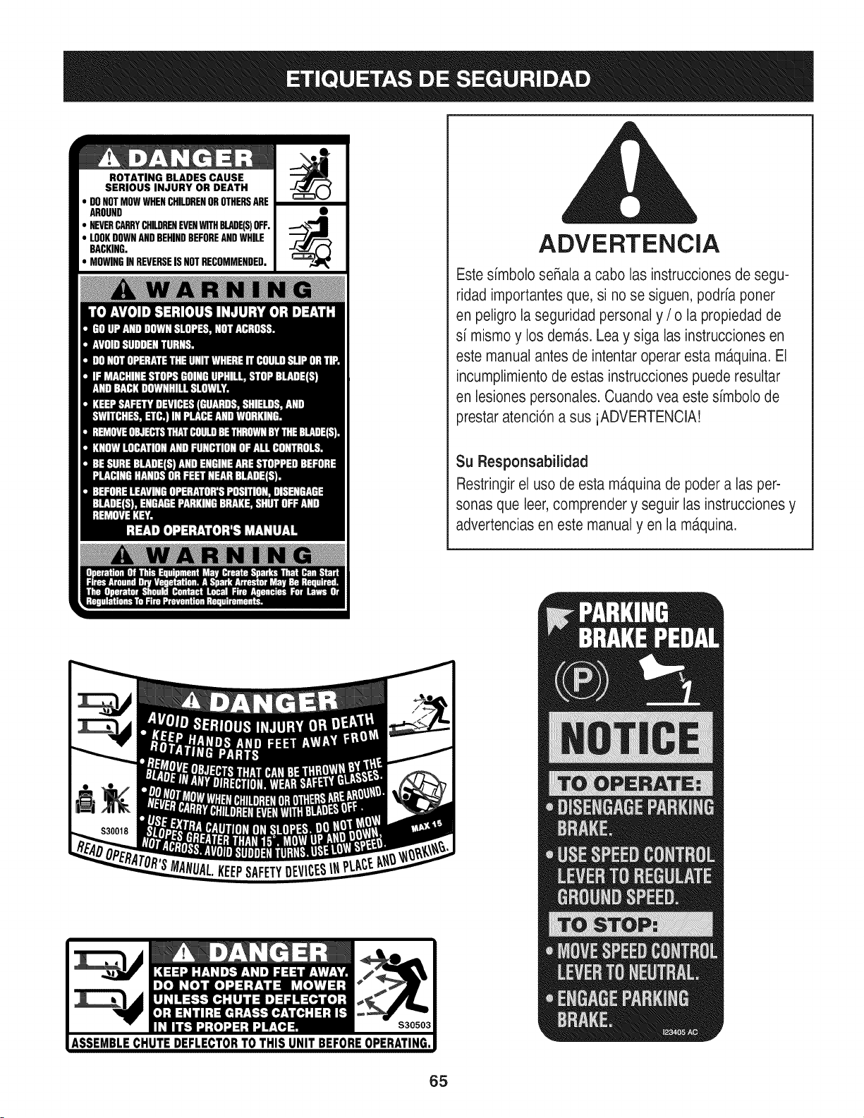
ROTATING BLADES CAUSE
SERIOUS INJURY OR DEATH
DONOTMOWWHENCHILDRENOROTHERSARE
AROUND
NEVERCARRYCHILDRENEVENWITHBLADE(S)OFF.
LOOKDOWNANDBEHINDBEFOREANDWHILE
BACKING.
MOWINGINREVERSEISNOTRECOMMENDED.
ADVERTENCIA
Este simbolo seRalaa cabo las instrucciones de segu-
ridad importantesque, si no se siguen, podria poner
en peligro la seguridad personal y / o la propiedad de
si mismo y los dem,_s.Lea y siga las instrucciones en
este manual antes de intentar operar esta m_tquina.El
incumplimientode estas instruccionespuede resultar
en lesiones personales. Cuando vea este simbolo de
prestar atenci6n a sus iADVERTENCIA!
Su Responsabilidad
Restringirel uso de esta ma.quinade poder a las per-
sonas que leer,comprender y seguir las instruccionesy
advertencias en este manual yen la m,_quina.
65
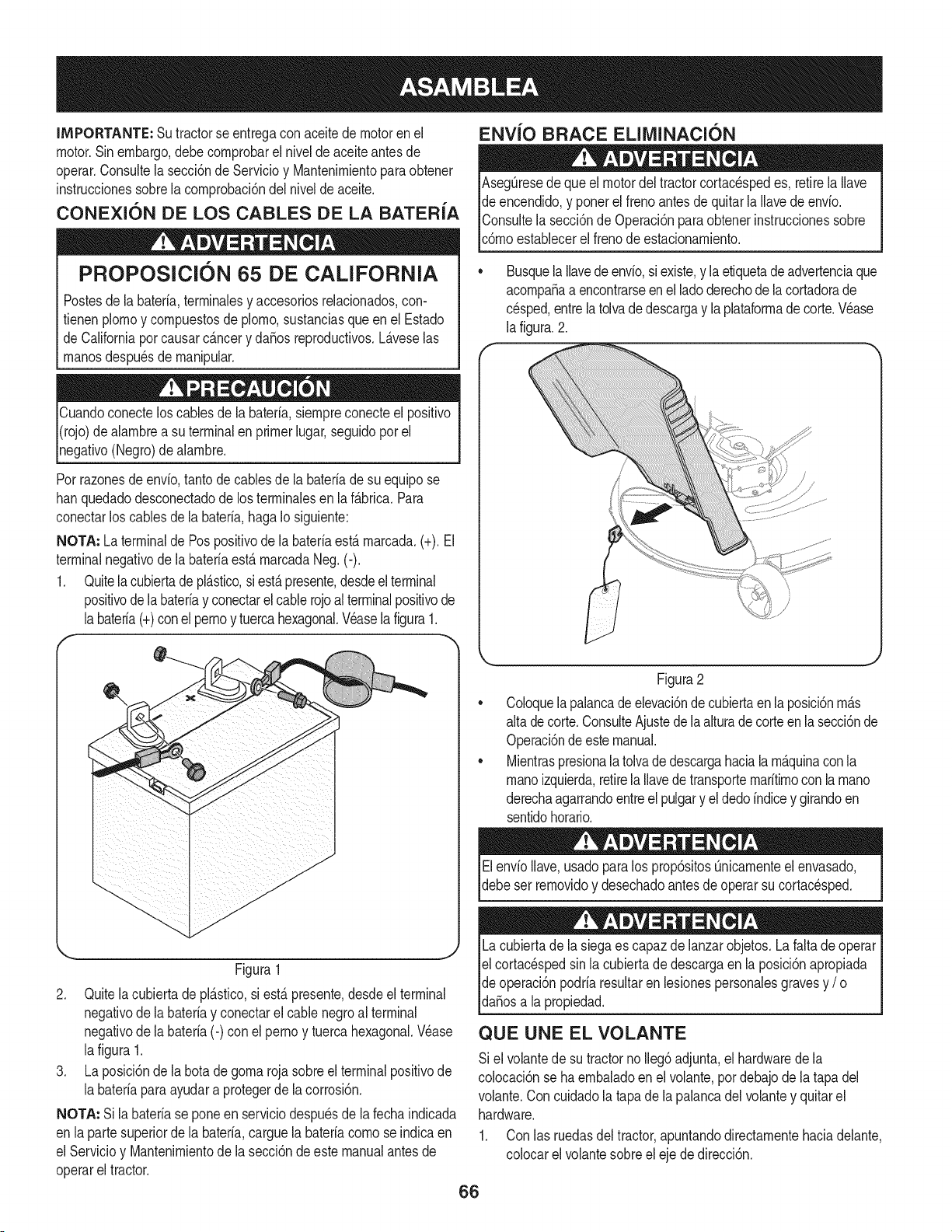
IMPORTANTE: Sutractorse entregaconaceitedemotoren el
motor.Sinembargo,debecornprobarel niveldeaceiteantesde
operar.Consultela secci6nde Servicioy Mantenirnientopara obtener
instrucdonessobrelacornprobad6ndel nivelde aceite.
CONEXION DE LOS CABLES DE LA BATERIA
PROPOSlClON 65 DE CALIFORNIA
Postesde la bateria,terrninalesy accesoriosrelacionados,con-
fienen plornoy cornpuestosde plorno,sustanciasqueen el Estado
de Californiaporcausarc_.ncery dafiosreproducfivos.L_.veselas
rnanosdespu6sde rnanipular.
Cuandoconecteloscablesde la bateria,siernpreconecteel posifivo
I(rojo)dealarnbrea su terminalen primerlugar,seguidopor el
pgafivo (Negro)de alarnbre.
Porrazonesde envio,tantode cablesde la bateriade su equipose
hanquedadodesconectadode los terrninalesen laf_.brica.Para
conectarlos cablesde la bateria,hagaIo siguiente:
NOTA: La terminalde Pospositivode la bateriaest,.rnarcada.(+). El
terminalnegativode labateriaest&rnarcadaNeg.(-).
1. Quitela cubiertade pl&stico,si est&presente,desdeelterminal
positivode labateriay conectarelcablerojo al terminalpositivode
Jabateria(+)conel pernoy tuercahexagonal.Veaselafigura1.
f --,,
ENVlO BRACE ELllVIINACI(SN
AsegQresedequeel motordel tractorcortacespedes, retirelaIlave
de encendido,y ponerel frenoantesde quitarla Ilavede envio.
IConsultela secci6nde Operaci6nparaobtenerinstruccionessobre
lc6rnoestablecerel frenode estacionarniento.
Busquela Ilavedeenvio,siexiste,y la etiquetade advertenciaque
acornpafiaa encontrarseenel ladoderechode lacortadorade
cesped,entrela tolvade descargay la plataforrnadecorte.Vease
la figura.2.
Figura1
2. Quitelacubierta de pl_.stico,si est,. presente,desdeel terminal
negativode la bateriay conectarel cable negroal terminal
negativode la bateria(-) con el perno y tuercahexagonal.V6ase
lafigura 1.
3. La posici6nde la botade gorna rojasobreel terminalpositivode
la bateriaparaayudara protegerde la corrosi6n.
NOTA: Si labateriase pone en serviciodespuesde la fechaindicada
en lapartesuperiorde la bateria,carguela bateriacornose indicaen
el Servicioy Mantenirnientode la secci6nde este manualantesde
operarel tractor.
Figura2
Coloquela palancade elevaci6nde cubiertaen la posici6nrn_.s
alta de corte.ConsulteAjustede la alturade corteen la secci6nde
Operaci6ndeestemanual.
Mientraspresionalatolvadedescargahaciala rn_.quinaconla
rnanoizquierda,retirela Ilavedetransporternaritirnoconla rnano
derechaagarrandoentreel pulgary el dedoindicey girandoen
sentidohorario.
ElenvioIlave,usadoparalos prop6sitosQnicarnenteel envasado,
debeser rernovidoy desechadoantesde operarsu cortacesped.
Lacubiertade la siegaes capazdelanzarobjetos.La faltade operar
el cortac6spedsin la cubiertade descargaen la posici6napropiada
de operaci6npodriaresultaren lesionespersonalesgravesy / o I
ldafiosa a propedad. j
QUE UNE EL VOLANTE
Si el volantede su tractorno Ileg6adjunta,el hardwarede la
colocaci6nse haernbaladoenel volante,pordebajode latapa del
volante.Con cuidadola tapade lapalancadelvolantey quitarel
hardware.
1. Con las ruedasdeltractor,apuntandodirectarnentehaciadelante,
colocarel volantesobreeleje de direcci6n.
66
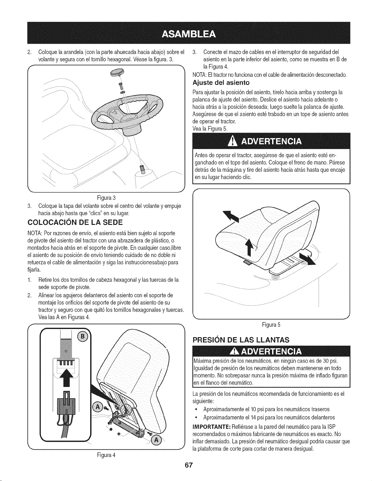
2. Coloquela arandela(con la parteahuecadahaciaabajo)sobreel
volantey seguracon el tornillohexagonal.Wase la figura.3.
f -,
Figura3
3. Coloquela tapadel volantesobreel centrodel volantey empuje
haciaabajohastaque "clics"en su lugar.
COLOCAClON DE LA SEDE
NOTA:Porrazonesde envfo,el asientoest,.bien sujetoal soporte
depivotedel asientodel tractorcon unaabrazaderadepl_.stico,o
montadoshaciaatr_.sen elsoportede pivote.Encualquiercaso,libre
el asientode su posici6nde envfoteniendocuidadode no dobleni
retuerzael cablede alimentaci6ny sigalas instruccionesabajopara
fijarla.
1. Retirelos dostornillosde cabezahexagonaly lastuercasde la
sedesoportede pivote.
2. Alinearlosagujerosdelanterosdel asientoconel soportede
montajelosorificiosdelsoportede pivotedelasientode su
tractory segurocon que quit6los tomilloshexagonalesy tuercas.
Vealas A en Figuras4.
f-
Figura4
3. Conecteel rnazode cablesen el interruptorde seguridaddel
asientoen la parteinferiordel asiento,como se muestraen Bde
laFigura4.
NOTA:Eltractorno funcionaconel cabledealimentaci6ndesconectado.
Ajuste del asiento
Paraajustarla posici6ndel asiento,firelohaciaarribay sostengala
palancade ajustedel asiento.Desliceel asientohaciaadelanteo
haciaatr_.sa la posici6ndeseada;luegosueltela palancadeajuste.
AsegQresedequeel asientoest_trabadoen untopede asientoantes
de operarel tractor.
Veala Figura5.
Antesde operarel tractor,asegQresede que el asientoest_en-
ganchadoen el topedel asiento.Coloqueel frenode mano. P_.rese
detr_.sde la m_.quinay tire delasientohaciaatr_.shastaqueencaje
en su lugarhaciendoclic.
Figura5
PFIESl0N DE LAS LLANTAS
M_.ximapresi6nde los neum_.ticos,en ning_ncaso es de30 psi.
Igualdadde presi6nde los neum_.ticosdebenmantenerseen todo
momento.Nosobrepasarnuncalapresi6nm_.ximade infiadofiguran
len e f anco de neum_.tco.
Lapresi6nde los neum_.ticosrecomendadade funcionamientoes el
siguiente:
• Aproximadamenteel 10psi paralos neum_.ticostraseros
• Aproximadamenteel 14psi paralos neum_.ticosdelanteros
IMPORTANTE: Refi_rasea lapareddel neum_.ticoparala ISP
recomendadoso m_.ximosfabricantede neum_.ticoses exacto.No
inflardemasiado.Lapresi6ndel neum_.ticodesigualpodriacausarque
laplataformade corteparacortarde maneradesigual.
67
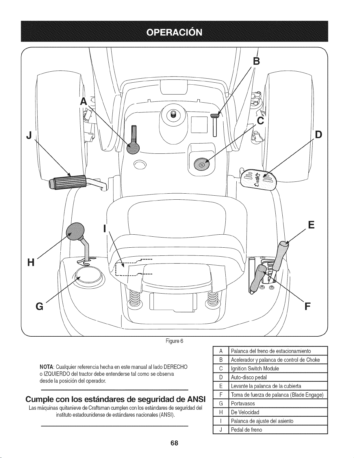
J
E
Figure6
NOTA:Cualquierreferenciahechaenestemanualal lado DERECHO
o IZQUIERDOdeltractordebeentendersetal como se observa
desde la posici6ndel operador.
Curnple con los est_ndares de seguridad de ANSI
Lasm_.quinasquitanievede Craftsmancumplenconlosest_.ndaresde seguridaddel
institutoestadounidensede est_.ndaresnacionales(ANSI).
D
A Palancadelfreno deestacionamiento
B Aceleradory palancade controlde Choke
C IgnitionSwitchModule
D Auto-discopedal
E Levantela palancade la cubierta
F Tomadefuerzade palanca(BladeEngage)
G Portavasos
H DeVelocidad
I Palancade ajustedel asiento
J Pedalde freno
J
68
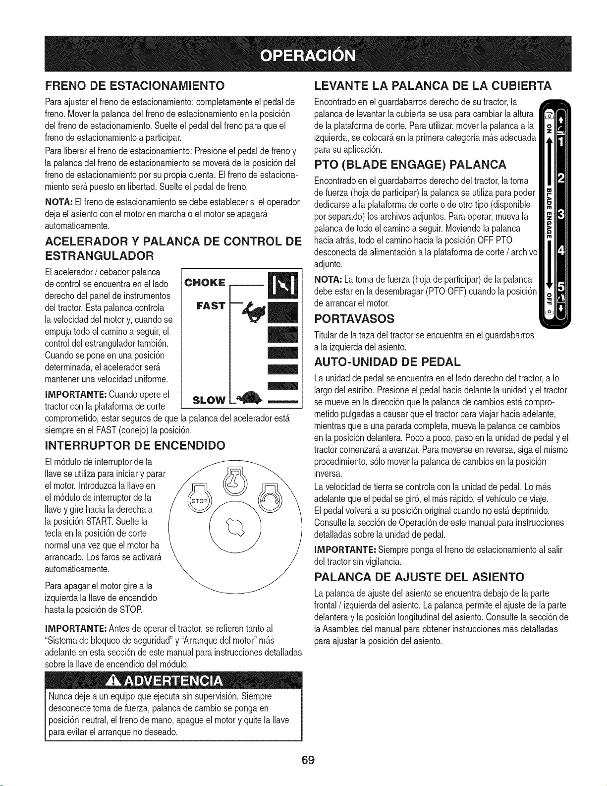
FRENO DE ESTACIONAIVllENTO
Paraajustarel frenodeestacionamiento:completamenteel pedalde
freno.Moverla palancadel frenode estacionamientoen la posM6n
delfrenode estacionamiento.Suelteel pedaldel frenoparaqueel
frenodeestacionamientoa participar.
Paraliberarel frenode estacionamiento:Presioneel pedaldefrenoy
la palancadel frenode estacionamientose mover_,dela posici6ndel
frenodeestacionamientoporsu propiacuenta.El frenode estaciona-
mientoser&puestoen libertad.Suelteel pedalde freno.
NOTA: Elfreno deestacionamientose debeestablecersi el operador
dejael asientocon el motoren marchao el motorse apagar&
autom&ficamente.
ACELERADOR Y PALANCA DE CONTROL DE
ESTRANGULADOR
Elacelerador/ cebadorpalanca
decontrol seencuentraen el lado
derechodel panel de instrumentos
deltractor.Estapalancacontrola
la velocidaddelmotory, cuandose
empujatodo el caminoa seguir,el
controldelestranguladortambi6n.
Cuandose poneenunaposici6n
determinada,el aceleradorser_.
mantenerunavelocidaduniforme.
IMPORTANTE: Cuandoopereel
tractorcon la plataformade corte
SLOW
comprometido,estarsegurosde quela palancadelaceleradorest,.
siempreenel FAST(conejo)la posici6n.
INTERRUPTOR DE ENCENDIDO
Elm6dulode interruptorde la
Ilavese utilizapara iniciary parar
el motor.IntroduzcalaIlaveen
el m6dulode interruptorde la
Ilavey gire haciala derechaa
la posici6nSTART.Sueltela
teclaen la posici6nde corte
normalunavezque el motorha
arrancado.Losfarosseactivar_.
autom&ticamente.
Paraapagarel motorgirea la
izquierdala Ilavede encendido
hastala posici6ndeSTOR
IMPORTANTE: Antesde operarel tractor,se refierentantoal
"Sistemadebloqueode seguridad"y "Arranquedel motor"m_.s
adelanteen esta secci6nde este manualpara instruccionesdetalladas
sobrela Ilavede encendidodelm6dulo.
Nuncadejea un equipoque ejecuta sinsupervisi6n.Siempre
desconectetomade fuerza,palancade cambiose pongaen
posici6nneutral,el frenode mano,apagueel motory quitela Ilave
paraevitarel arranqueno deseado.
LEVANTE LA PALANCA DE LA CUBIERTA
Encontradoenel guardabarrosderechodesu tractor,la
palancade levantarla cubierta se usaparacambiarlaaltura
de la plataformadecorte. Parautilizar,moverla palancaa la
izquierda,se colocar_,en laprimeracategoriam_.sadecuada
parasu aplicaci6n.
PTO (BLADE ENGAGE) PALANCA
Encontradoenel guardabarrosderechodeltractor,latoma
de fuerza(hojade participar)la palancase utilizaparapoder
dedicarsea laplataformade corteode otto tipo(disponible
porseparado)los archivosadjuntos.Paraoperar,muevala
palancade todo elcaminoa seguir.Moviendola palanca
haciaatr_.s,todo el caminohacia laposici6nOFF PTO
desconectade alimentaci6na la plataformade corte/ archivo
adjunto.
NOTA: Latoma de fuerza (hojade participar)de la palanca
debeestar en la desembragar(PTOOFF)cuandola posici6n
de arrancarel motor.
PORTAVASOS
Titulardela taza del tractorse encuentraenel guardabarros
a la izquierdadel asiento.
AUTO-UNIDAD DE PEDAL
Launidadde pedalse encuentraenel ladoderechodel tractor,a Io
largodelestribo.Presioneel pedalhaciadelantela unidady el tractor
semueveen ladirecci6nquela palancade cambiosest,. compro-
metidopulgadasa causarqueel tractorparaviajarhaciaadelante,
mientrasquea unaparadacompleta,muevala palancade cambios
en la posici6ndelantera.Pocoa poco, pasoen la unidadde pedaly el
tractorcomenzar_,a avanzar.Paramoverseen reversa,sigael mismo
procedimiento,s61omoverla palancade cambiosenla posici6n
inversa.
Lavelocidadde tierrase controlacon la unidadde pedal.Lom_.s
adelanteque el pedal segir6, el m_.sr_.pido,elvehiculode viaje.
Elpedalvolver_,a su posici6noriginalcuandono est,. deprimido.
Consultela secci6nde Operaci6nde estemanualparainstrucciones
detalladassobrela unidadde pedal.
IMPORTANTE: Siemprepongael frenode estacionamientoal salir
del tractorsin vigilancia.
PALANCA DE AJUSTE DEL ASIENTO
Lapalancade ajustedel asientose encuentradebajode la parte
frontal/izquierda delasiento.La palancapermiteel ajuste de la parte
delanteray la posici6nlongitudinaldelasiento.Consultela secci6nde
laAsambleadel manualparaobtenerinstruccionesm_.sdetalladas
paraajustarla posici6ndelasiento.
69
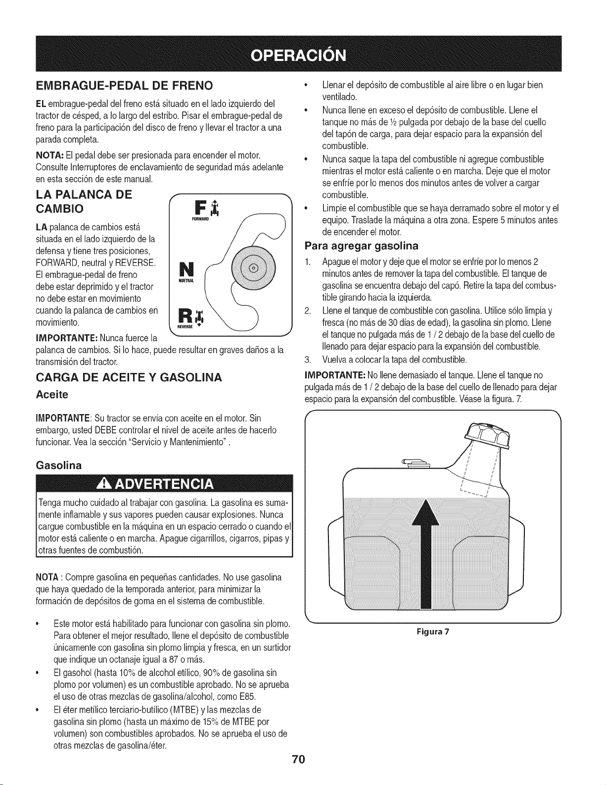
EMBRAGUE-PEDAL DE FRENO
ELembrague-pedaldel frenoest,.situadoen el ladoizquierdodel
tractorde c_sped,a Io largodel estribo.Pisarel embrague-pedalde
frenoparalaparticipaci6ndel discode frenoy Ilevarel tractora una
paradacompleta.
NOTA: El pedaldebeser presionadaparaencenderel motor.
ConsulteInterruptoresde enclavamientode seguridadm_.sadelante
enesta secci6nde este manual.
LA PALANCA DE
CANIBIO
LA palancade cambiosest,.
situadaenel lado izquierdode la
defensay tienetresposiciones,
FORWARD,neutraly REVERSE.
Elembrague-pedalde freno
debeestardeprimidoy el tractor
nodebe estar en movimiento
cuandolapalancade cambiosen
movimiento.
IMPORTANTE: Nuncafuercela
palancade cambios.Si Io hace,puederesultarengravesdaSosa la
transmisi6ndel tractor.
CARGA DE ACEITE Y GASOLINA
Aceite
IMPORTANTE:Su tractorse enviacon aceiteen el motor.Sin
embargo,ustedDEBEcontrolarel nivelde aceiteantesde hacerlo
funcionar.Vealasecci6n"Servicioy Mantenimiento".
Gasolina
Tengamuchocuidadoal trabajarcon gasolina.Lagasolinaes suma-
menteinflamabley sus vaporespuedencausar explosiones.Nunca
carguecombustibleenla m_.quinaen un espaciocerradoo cuandoel
motorest,.calienteo en marcha.Apaguecigarrillos,cigarros,pipasy
otrasfuentesde combusti6n.
NOTA: Compregasolinaen pequeSascantidades.No usegasolina
quehayaquedadode la temporadaanterior,paraminimizarla
formaci6nde dep6sitosdegomaenel sistemadecombustible.
• Llenarel dep6sitode combustibleal aire libreo en lugar bien
ventilado.
• NuncaIleneen excesoel dep6sitode combustible.Lleneel
tanqueno m_.sde 1/2pulgadapordebajode la basedel cuello
del tap6ndecarga, paradejar espaciopara la expansi6ndel
combustible.
• Nuncasaquela tapadel combustibleni agreguecombustible
mientrasel motorest,.calienteo en marcha.Dejeque el motor
se enfrie porIo menosdos minutosantesdevolvera cargar
combustible.
• Limpieel combustibleque sehayaderramadosobreel motory el
equipo.Trasladela m_.quinaa otrazona.Espere5 minutosantes
de encenderel motor.
Para agregar gasolina
1. Apagueel motory dejequeelmotorseenfrieporIomenos2
minutosantesde removerlatapadelcombustible.Eltanquede
gasolinaseencuentradebajodelcap& Retirelatapadelcombus-
tiblegirandohaciala izquierda.
2. Lleneel tanquede combustiblecongasolina.Utilices61olimpiay
fresca(nom_.sde30diasde edad),lagasolinasinplomo.Llene
el tanqueno pulgadam_.sde 1/ 2 debajode la basedel cuellode
Ilenadoparadejarespacioparala expansi6ndelcombustible.
3. Vuelvaa colocarla tapadel combustible.
IMPORTANTE:No Ilenedemasiadoel tanque.Lleneeltanqueno
pulgadam_.sde 1/ 2debajodela basedelcuellode Ilenadoparadejar
espacioparalaexpansi6ndel combustible.Wase la figura.7.
• Estemotorest,.habilitadoparafuncionarcon gasolinasinplomo.
Paraobtenerel mejor resultado,Ileneel dep6sitodecombustible
Onicamentecongasolinasin plomolimpiay fresca,enun surtidor
queindiqueun octanajeigual a 87 o m_.s.
• Elgasohol(hasta10%dealcoholetilico,90%degasolinasin
plomoporvolumen)es un combustibleaprobado.No seaprueba
el usode otrasmezclasdegasolina/alcohol,como E85.
• El_ter mefilicoterciario-butilico(MTBE)y las mezclasde
gasolinasin plomo(hastaun m_.ximode 15%de MTBEpor
volumen)son combustiblesaprobados.No se apruebaeluso de
otrasmezclasdegasolina/eter.
Figura 7
7O
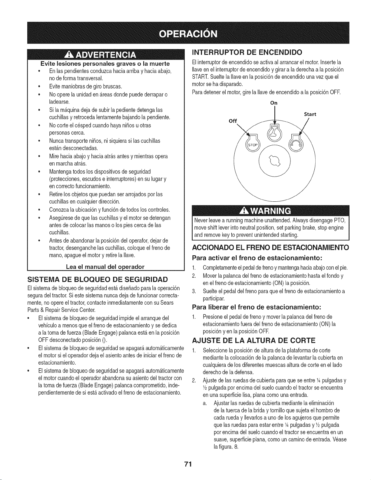
Evite lesiones personales graves o la muerte
• Enlas pendientesconduzcahaciaarribay haciaabajo,
node forrnatransversal.
• Eviternaniobrasde giro bruscas.
• No operela unidaden _.reasdonde puedederraparo
ladearse.
• Si larn_.quinadeja de subirla pedientedetengalas
cuchillasy retrocedalentarnentebajandolapendiente.
• No corteel c_spedcuandohayaniSosu otras
personascerca.
• NuncatransporteniSos,ni siquierasi lascuchillas
est_.ndesconectadas.
• Mirehaciaabajoy haciaatr_.santesy rnientrasopera
enrnarchaatr_.s.
• Mantengatodoslosdispositivosde seguridad
(protecciones,escudose interruptores)ensu lugary
encorrectofuncionarniento.
• Retirelos objetosquepuedanserarrojadospor las
cuchillasencualquierdirecci6n.
• Conozcala ubicaci6ny funci6nde todoslos controles.
• AsegQresede quelas cuchillasy el motor sedetengan
antesde colocarlas rnanoso los piescercade las
cuchillas.
• Antesde abandonarlaposici6ndeloperafor,dejarde
tractor,desenganchelascuchillas,coloqueel frenode
rnano,apagueel motor y retirela Ilave.
Lea el manual del o erador
SISTEMA DE BLOQUEO DE SEGURIDAD
Elsisternade bloqueode seguridadest,.dise_adopara la operaci6n
seguradel tractor.Si estesisternanuncadeja de funcionarcorrecta-
rnente,no opereel tractor,contacteinrnediatarnentecon suSears
Parts& RepairServiceCenter.
• Elsisternade bloqueode seguridadirnpideel arranquedel
vehiculoa rnenosqueel frenode estacionarnientoy se dedica
a latornadefuerza (Blade Engage)palancaest,. en la posici6n
OFFdesconectadoposici6nO.
• Elsisternade bloqueode seguridadseapagar&autorn&ticarnente
el motorsi el operadordeja el asientoantesde iniciarel frenode
estacionarniento.
• Elsisternade bloqueode seguridadseapagar&autorn&ticarnente
el motorcuandoel operadorabandonasuasientodel tractorcon
la tornadefuerza (Blade Engage)palancacornprornetido,inde-
pendienternentede si est,. activadoel frenodeestacionarniento.
INTERRUPTOR DE ENCENDIDO
Elinterruptordeencendidose activaal arrancarel motor.Insertela
Ilaveen el interruptorde encendidoy girara laderechaa la posici6n
START.Sueltela Ilaveenla posici6ndeencendidouna vez que el
motorse ha disparado.
Paradetenerel motor,gire la Ilavede encendidoa la posici6nOFE
On
Start
off
Neverleavea runningmachineunattended.AlwaysdisengagePTO,
moveshift leverinto neutralposition,setparkingbrake,stopengine
and removekeyto preventunintendedstarting.
ACCIONADO EL FRENO DE ESTACIONAMIENTO
Para activar el freno de estacionamiento:
1. Completarnenteelpedaldefrenoy rnantengahaciaabajoconel pie.
2. Moverlapalancadel frenode estacionarnientohastael rondoy
en elfrenode estacionarniento(ON)la posici6n.
3. Suelteel pedaldel freno paraqueel frenode estacionarnientoa
participar.
Para liberar el freno de estacionamiento:
1. Presioneel pedalde frenoy moverla palancadel freno de
estacionarnientofueradelfrenode estacionarniento(ON)la
posici6nyen la posici6nOFE
AJUSTE DE LA ALTURA DE CORTE
Seleccionelaposici6ndealturade la plataforrnade corte
rnediantelacolocaci6ndela palancade levantarlacubiertaen
cualquierade los diferentesrnuescasalturadecorteen el lado
derechode la defensa.
Ajustede las ruedasde cubiertaparaquese entre1Apulgadasy
1/2pulgadapot encirnadel suelocuandoel tractorseencuentra
en unasuperficielisa, planacornouna entrada.
a. Ajustarlas ruedasde cubierta rnediantela elirninaci6n
de latuerca de la brida y tornilloquesujetael hornbrode
cada rueday Ilevarlosa uno de los agujerosqueperrnite
que las ruedasparaestar entre1Apulgadasy 1/2pulgada
porencirnadelsuelocuandoel tractorse encuentraen un
suave,superficieplan& cornoun carninode entrada.Wase
lafigura.8.
71
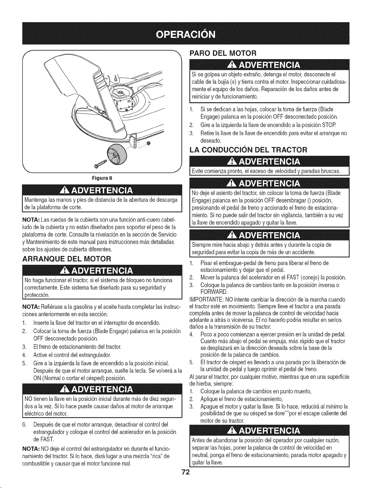
PARO DEL MOTOR
Si se golpeaun objetoextra,o, detengael motor,desconecteel
cablede la bujfa(s) y tierracontrael motor.Inspeccionarcuidadosa-
rnenteel equipode losda_os. Reparaci6nde losda_osantes de
reiniciary defuncionarniento.
1. Si se dedicanalas hojas,colocarlatornadefuerza(Blade
Engage)palancaen laposici6nOFFdesconectadoposici6n.
2. Girea la izquierdala Ilavede encendidoa la posici6nSTOR
3. RetirelaIlavede la Ilavede encendidoparaevitarelarranqueno
deseado.
LA CONDUCCION DEL TRACTOR
Figura 8
Mantengalasrnanosy piesde distanciadela aberturade descarga
de la plataforrnadecorte.
NOTA: Las ruedasde la cubiertasonuna funci6nanti-cuerocabel-
ludode la cubiertay no est_.ndiseSadosparasoportarel pesode la
plataforrnade corte.Consultelanivelaci6nen la secci6nde Servicio
y Mantenirnientode este manualpara instruccionesrn_.sdetalladas
sobrelos ajustesde cubierta diferentes.
ARRANQUE DEL MOTOR
No hagafuncionarel tractor,si el sisternade bloqueonofunciona
correctarnente.Este sisternarue diseSadopara su seguridady
protecci6n.
NOTA: Refi_rasea lagasolinay elaceitehastacornpletarlas instruc-
cionesanteriorrnenteenesta secci6n.
1. InsertelaIlavedel tractoren el interruptorde encendido.
2. Colocarlatornade fuerza(Blade Engage)palancaen la posici6n
OFFdesconectadoposici6n.
3. Elfrenode estacionarnientodel tractor.
4. Activeel controldel estrangulador.
5. Girea la izquierdala Ilavede encendidoa la posici6ninicial.
Despu_sde que el motorarranque,sueltela tecla.Se volver_,a la
ON (Normalo cortar el cesped)posici6n.
NOtienenla Ilaveen laposici6ninicialdurantern_.sdediez segun-
dosa la vez.Si Io hacepuedecausardaSosal motorde arranque
el_ctricodel motor.
6. Despu_sde que el motorarranque,desactivarel control del
estranguladory coloqueel controldel aceleradoren la posici6n
de FAST.
NOTA: NO deje el controldel estranguladoren duranteel funcio-
narnientodeltractor.Si Iohace,dar_.lugara unarnezcla"rica"de
combustibley causarqueel motorfuncionernal.
Evitecornienzapronto,el excesodevelocidady paradasbruscas.
Nodejeel asientodel tractor,sin colocarla tornade fuerza(Blade
Engage)palancaen laposici6nOFFdesernbragar0 posici6n,
presionandoel pedalde frenoy accionadoel frenode estaciona-
rniento.Sino puedesalirdel tractorsin vigilancia,tarnbi_na suvez
la Ilavedeencendidoapagadoy quitarla Ilave.
Siernpremire haciaabajo y detr_.santesy durantela copiade
seguridadpara evitarla copiade rn_.sde un accidente.
1. Pisarel ernbrague-pedaldefrenoparaliberarel frenode
estacionarnientoy dejarque el pedal.
2. Moverla palancadel aceleradoren el FAST(conejo)la posici6n.
3. Coloquelapalancade carnbiostanto en la posici6ninversao
FORWARD.
IMPORTANTE:NOintentecarnbiarla direcci6nde la rnarchacuando
el tractorest_enrnovirniento.SiernpreIleveel tractora unaparada
cornpletaantesdemoverla palancade controlde velocidadhacia
adelantea atr_.soviceversa.El nohacerlopodriaresultaren serios
da_osa la transrnisi6nde su tractor.
4. Pocoa pococornienzana ejercerpresi6nen la unidadde pedal.
Cuantorn_.sabajoel pedalse ernpuja,rn_.sr_.pidoqueel tractor
se desplazar_,en ladirecci6ndeseadasobrela basede la
posici6nde lapalancade carnbios.
5. Eltractorde c_spedes Ilevadoa unaparadapor la liberaci6nde
la unidadde pedaly luegooprirnirel pedaldefreno.
AI pararel tractor,por cualquierrnotivo,rnientrasque en una superficie
de hierba,siernpre:
1. Coloquelapalancade carnbiosen puntornuerto,
2. Apliqueel frenodeestacionarniento,
3. Apagueel motory quitar laIlave.Si Io hace,reducir_,al rninirnola
posibilidadde que sucesped sedore'"'porel escapecalientedel
motorde su tractor.
Antesde abandonarla posici6ndel operadorporcualquierraz6n,
separarlashojas,ponerla palancade control de velocidaden
neutral,pongael frenode estacionarniento,paradamotorapagadoy
quitarla Ilave.
72
CONDUCCI6N EN LAS LADERAS
INVOLUCRAR A LOS BLADES
Refierenal anchodela pendienteen la seguridadde las pr_.cticasde
operaci6nirnportantesecci6ndel manualpara ayudara deterrninar
zonasde laderadondepuedeoperarel tractorcon totalseguridad.
Nocorteel cespeden pendientescon una inclinaci6nde rn_.sde 15
grados(unaurnentode aproxirnadarnente2-1/2pies cada 10pies).
Eltractorpuedevolcary causarlesionesgraves.
• Corteel c_spedy las pendientes,nuncatransversal.
• Tengaextrernaprecauci6nalcarnbiarde direcci6nen las
pendientes.
• Watchpara los agujeros,grietas,baches,piedrasu otrosobjetos
ocultos.Terrenoirregularpuederevertirla rn_.quina.Elcesped
altopuedeocultarobst_.culos.
• Evitegirar cuandosecircula por una pendiente.Si unavez,debe
hacerse,a suvez porla pendiente.El regresode unapendiente
aurnentala posibilidadde un rollover.
• Evitedetenersecuandoseconduce por una pendiente.Si es
necesariodetenerrnientrasse conducepot unapendiente,
puestaen rnarchasinproblernasy con cuidadoparareducirla
posibiNdadde volteareltractorhaciaatr_.s.
Participaci6nde la tornade fuerza(Blade Engage)lastransferenciasde
energfaa la plataforrnadecorteo deotrotipo(disponibleporseparado)
losarchivosadjuntos.Paraparticiparde lashojas,hagaIosiguiente:
1. Moverlapalancade controldel aceleradora la r_.pida(conejo)la
posici6n.
2. Sujetela tornade fuerza(Blade Engage)y girarla palancade
todo el carninoa seguira los novios(ON) la posici6n.
3. Mantengala palancadel aceleradoren el FAST(conejo)la
posici6nparael usorn_.seficientede laplataforrnade corteo de
otro tipo (disponiblepor separado)los archivosadjuntos.
NOTA: Elmotorse apagar_,autom_.ticarnentesi latornade fuerza
est,.comprornetidocon la palancade carnbiosen la posici6nde
rnarchaatr_.scon laNavede encendidoen la posici6nON.
USO DE LA CUBIERTA DE LEVANTE LA
PALANCA DE
Paraelevarla plataforrnade corte,moverla palancadeelevaci6nde
cubiertaa la izquierda,luegosecolocaen la ranurarn_.sadecuada
parasu apNcaci6n.ConsulteAjustelaalturade corteanteriorrnenteen
estasecci6n.
73
CORTAR
Paraayudara evitar el contactocon lacuchillao unalesi6nen
elobjetolanzado,Mantengaa los espectadores,losayudantes,
los niSosy las mascotaspor Io menos75piesde distandade la
m_.quinamientrasest,.enfundonamiento.Paradade lam_.quina,si
alguienentraenel _.rea.
La siguienteinformaci6nser_.Qfilcuandose ufiliza la plataformade
corteconsu tractor:
Plande su patr6nde corte paraevitar la descargade materiales
hada lascarreteras,aceras,transeQntes,etc. Adem_.s,evitematerial
quese descargacontraunaparedo unaobstrucd6nque puede
causaralta materiala rebotarhaciael operador.
FAROS
• LasI&mparasest&nONcuandoel motordeltractorse est&
ejecutando.
• Lasluces seapaga cuandola Ilavede contactose muevea la
posici6nSTOE
• Nocorteel c6speda la velocidadde terrenoelevado,especial-
mentesi se ha instaladoun kitde mantilloo colectorde cesped.
• Paraobtenerlos mejoresresultadosse recomiendaquelas
dos primerasvueltassecortar&conla aprobaci6nde lagesti6n
arrojadohaciael centro.Tras lasdos primerasvueltas,invertirel
sentidode lanzarla descargahaciael exteriordela balanzade
corte.Estoledar&una mejoraparienciaal cesped.
• Nocorteel cespeddemasiadocorto. Pastocorto invita crec-
imientodemalas hierbasy los amarilloscon rapidezen el tiempo
seco.
• Cortarel c6spedsiemprese debe hacercon el motora todogas.
• Bajolascondicionesm_.spesadas,puedesernecesariovolversobre
lazonadelcortepor segundavezparaobteneruncortelimpio.
• NOintentecortarespesamalezay malashierbasy el pastomuyalto.
Sutractorest&diseSadoparacortarelc6sped,uncepillonoest&claro.
• Mantengalas cuchillasafiladasy sustituirlascuchillasen caso
dedesgaste.ConsulteHojas de corte en el servicioy la secd6n
Mantenimientodeeste manualdeinstruccionesdeafilar la hoja
adecuada.
74
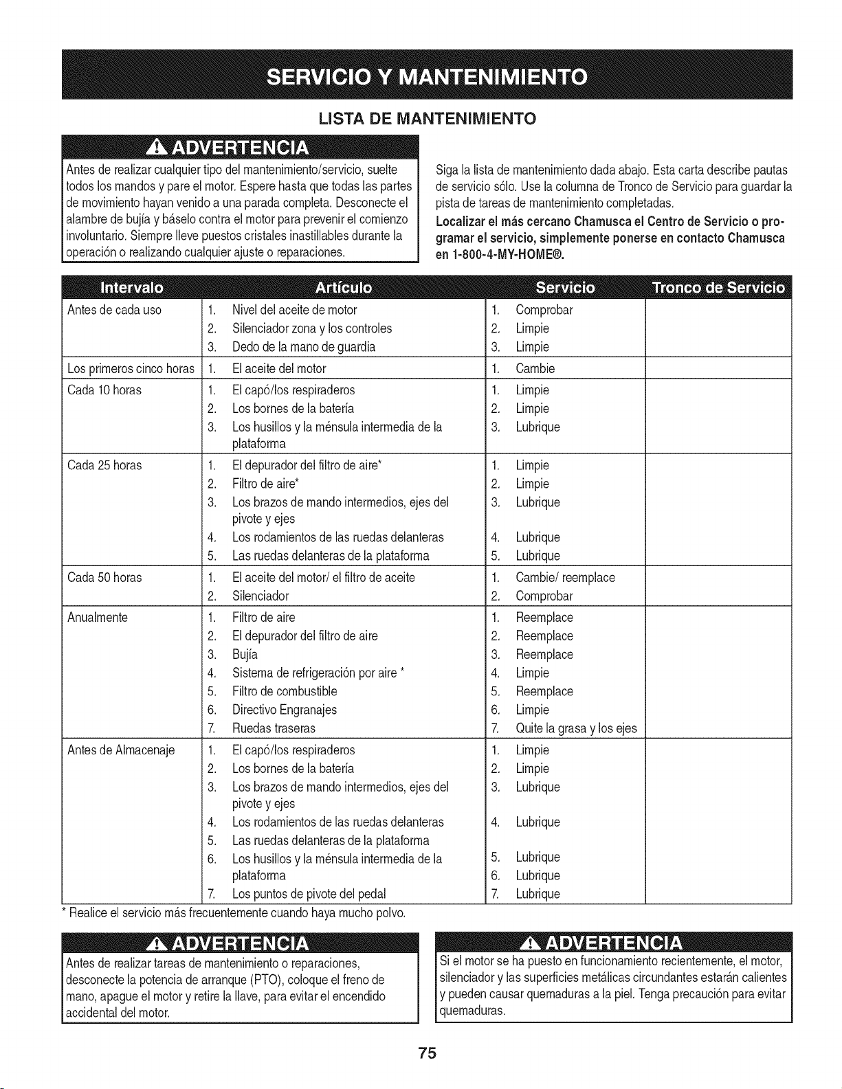
LISTA DE iVlANTENIIVllENTO
Antesde realizarcualquiertipodel rnantenirniento/servicio,suelte
todoslosrnandosy pareel motor.Esperehastaquetodaslaspartes
de rnovirnientohayanvenidoa unaparadacornpleta.Desconecteel
alarnbrede bujiay b_.selocontrael motorparaprevenirel cornienzo
involuntario.SiernpreIleve puestoscristalesinastillablesdurantela
operaci6no realizandocualquierajusteo reparaciones.
Sigala listade rnantenirnientodadaabajo.Esta carta describepautas
de servicios61o.Usela colurnnade Troncode Servicioparaguardar la
pistade tareasdernantenirnientocornpletadas.
Localizarel rn_scercanoChamuscael Centrode Servicio o pro-
gramar el servicio,simplementeponerseen contactoChamusca
en 1-800-4-MY-HOME®.
Antesde cadauso
Los prirneroscinco horas
Cada 10horas
Cada25horas
Cada50horas
Anualrnente
Antesde Alrnacenaje
1. Niveldelaceitede motor
2. Silenciadorzonay loscontroles
3. Dedodela rnanode guardia
1. Elaceitedel motor
1. EIcap6/Iosrespiraderos
2. Losbornesdela bateria
3. Loshusillosy larn_nsulainterrnediade la
plataforrna
1. Eldepuradordelfiltro de aire*
2. Filtrode aire*
3. Losbrazosde rnandointerrnedios,ejes del
pivotey ejes
4. Los rodarnientosde las ruedasdelanteras
5. Las ruedasdelanterasde la plataforrna
1. Elaceitedel motor/el filtrodeaceite
2. Silenciador
1. Filtrode aire
2. Eldepuradordel filtro de aire
3. Bujia
4. Sisternade refrigeraci6npor aire *
5. Filtrode combustible
6. DirectivoEngranajes
7. Ruedastraseras
1. EIcap6/Iosrespiraderos
2. Loshomesde la bateria
3. Losbrazosde rnandointerrnedios,ejes del
pivotey ejes
4. Los rodarnientosdelas ruedasdelanteras
5. Las ruedasdelanterasde la plataforrna
6. Loshusillosy larn_nsulainterrnediade la
plataforrna
7. Lospuntosde pivotedel pedal
Realiceel serviciorn_.sfrecuenternentecuandohayarnuchopolvo.
Antesde realizartareasde mantenirnientoo reparaciones,
desconectela potenciadearranque(PTO),coloqueel frenode
rnano,apagueel motory retirela Ilave,paraevitarelencendido
accidentaldel motor.
.
2.
3.
1.
1.
2.
3.
Cornprobar
Lirnpie
Lirnpie
Carnbie
Lirnpie
Lirnpie
Lubrique
1. Lirnpie
2. Lirnpie
3. Lubrique
4. Lubrique
5. Lubrique
1. Carnbie/reernplace
2. Cornprobar
1. Reernplace
2. Reernplace
3. Reernplace
4. Lirnpie
5. Reernplace
6. Lirnpie
7. Quitelagrasay los ejes
1. Lirnpie
2. Lirnpie
3. Lubrique
4. Lubrique
5. Lubrique
6. Lubrique
Z Lubrique
Si el motorse ha puestoen funcionarnientorecienternente,el motor,
silenciadory las superficiesrnet_.licascircundantesestar_.ncalientes
Iy puedencausarquernadurasa la piel.Tengaprecauci6nparaevitar
[quernaduras.
75
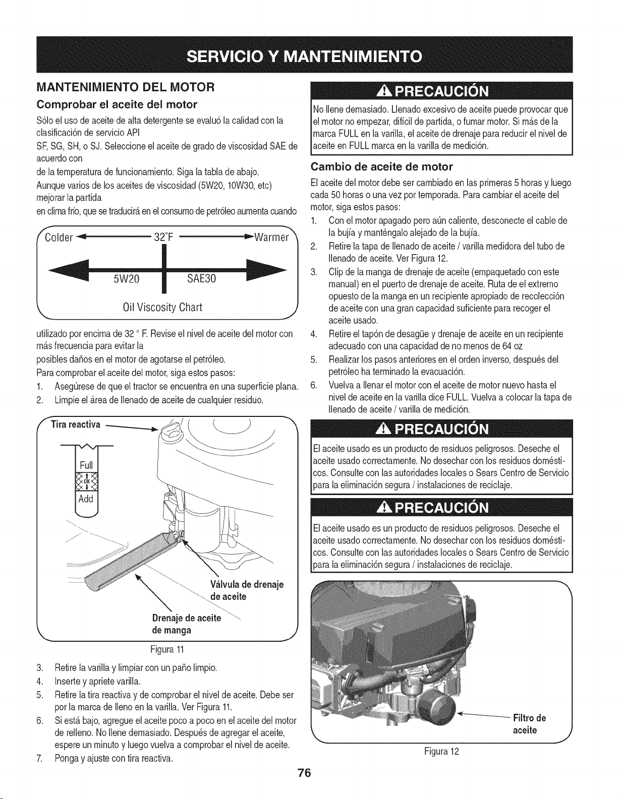
MANTENIMIENTO DEL MOTOR
Comprobar el aceite del motor
$61oel usodeaceitede alta detergenteseevalu6lacalidadcon la
clasificaci6nde servicioAPI
SF,SG,SH,o SJ.Seleccioneel aceitede gradode viscosidadSAEde
acuerdocon
de laternperaturadefuncionarniento.Sigalatablade abajo.
Aunquevariosdelos aceitesdeviscosidad(5W20,10W30,etc)
rnejorarla partida
enclirnafifo,quese traducirAen el consurnodepetr61eoaurnentacuando
Colder "< 32°F _Warmer
Oil Viscosity Chart
utilizadoporencirnade 32 o E Reviseel nivelde aceite del motorcon
rnAsfrecuenciaparaevitarla
posiblesdafiosen el motordeagotarseel petr61eo.
Paracornprobarel aceitedel motor,sigaestospasos:
1. AsegOresedequeel tractorse encuentraen una superficieplana.
2. Lirnpieel _.reade Ilenadode aceitede cualquierresiduo.
f Tira reactiva
V_lvulade drenaje
de aceite
Drenajede aceite
de manga
Figura11
3. Retirela variNay lirnpiarconun patioNrnpio.
4. Insertey aprietevarilla.
5. Retirela tira reactivay de cornprobarel nivelde aceite.Debeser
porla rnarcade Ilenoen la varilla. Ver Figura11.
6. Siest_ bajo,agregueel aceitepocoa pocoen el aceite del motor
de reNeno.1/oNenedernasiado.Despu_sde agregarel aceite,
espereunrninutoy luegovuelvaacornprobarel nivelde aceite.
7. Pongay ajustecon tira reactiva.
76
No Nenedernasiado.Llenadoexcesivodeaceitepuedeprovocarque
elmotorno ernpezar,diffcilde partida,o furnarmotor.Si rn_sde la
rnarcaFULLen lavarilla,el aceitede drenajepara reducirel nivelde
aceiteen FULLrnarcaen la varillade rnedici6n.
Cambio de aceite de motor
Elaceitedel motordebeset carnbiadoen las prirneras5 horasy luego
cada 50 horaso una vez por ternporada.Para carnbiarel aceitedel
motor,sigaestospasos:
1. Con el motorapagadopero aOncaliente,desconecteel cablede
la bujfay rnant_ngaloalejadode la bujfa.
2. Retirelatapa deIlenadode aceite / varillarnedidoradeltubo de
Nenadode aceite.Vet Figura12.
3. Clip de la rnangade drenajedeaceite(ernpaquetadocon este
manual)enel puertode drenajede aceite.Ruta de el extrerno
opuestode larnangaen un recipienteapropiadode recolecci6n
de aceitecon una gran capacidadsuficientepara recogerel
aceiteusado.
4. Retireel tap6nde desagOey drenajede aceite en un recipiente
adecuadocon unacapacidaddeno rnenosde64 oz
5. Realizarlos pasosanterioresenel ordeninverso,despu_sdel
petr61eohaterrninadola evacuaci6n.
6. Vuelvaa Nenarel motorconel aceitede motornuevohastael
nivelde aceiteen lavarilladice FULL.Vuelvaa colocar la tapa de
Ilenadode aceite/ varillade rnedici6n.
Elaceiteusadoes un productode residuospeligrosos.Desecheel
aceiteusadocorrectarnente.1/odesecharcon los residuosdorn_sti-
cos.Consultecon lasautoridadeslocaleso SearsCentrode Servicio
_aralaeNrninaci6nsegura/instalacionesde reciclaje.
Elaceiteusadoes un productode residuospeligrosos.Desecheel
aceiteusadocorrectarnente.1/odesecharcon los residuosdorn_sti-
cos.Consultecon lasautoridadeslocaleso SearsCentrode Servicio
[para a e rnnac6n segura/ nstaac onesde recc aje.
Figura12
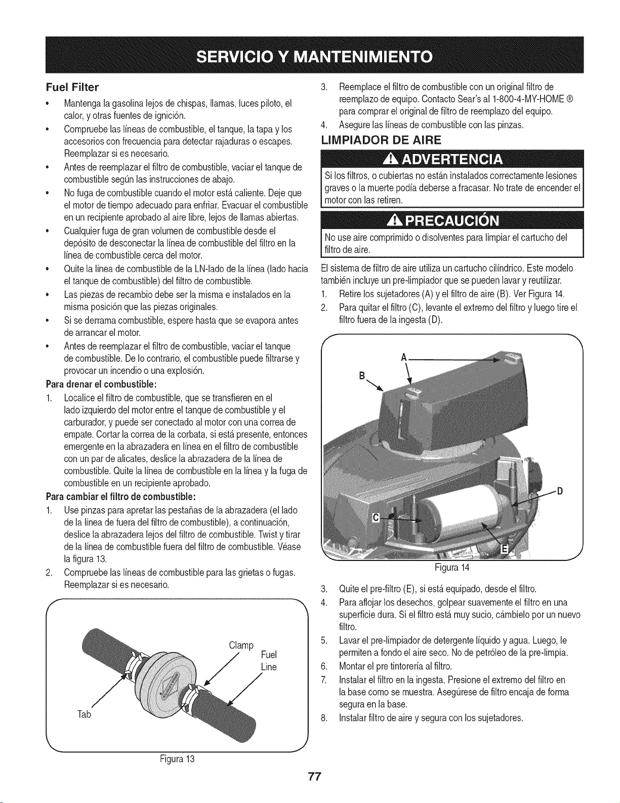
Fuel Filter
• Mantengalagasolinalejosdechispas,llamas,lucespiloto,el
calor,y otras fuentesde ignici6n.
• Cornpruebelas lineasde combustible,eltanque,la tapay los
accesoriosconfrecuenciaparadetectarrajaduraso escapes.
Reernplazarsi es necesario.
• Antesde reernplazarel filtro de combustible,vaciarel tanquede
combustiblesegQnlas instruccionesdeabajo.
• No fugadecombustiblecuandoel motorest,.caliente.Dejeque
el motordetiernpoadecuadopara enfriar.Evacuarel combustible
enun recipienteaprobadoal airelibre,lejosde llamasabiertas.
• Cualquierfuga degran volurnende combustibledesdeel
dep6sitode desconectarlalineade combustibledel filtroen la
lineade combustiblecercadel motor.
• Quitela lineadecombustibledela LN-ladode la linea(ladohacia
el tanquede combustible)del filtro de combustible.
• Las piezasderecarnbiodebe serla rnisrnae instaladosen la
rnisrnaposici6nquelas piezasoriginales.
• Si sederrarnacombustible,esperehastaque seevaporaantes
dearrancarel motor.
• Antesde reernplazarel filtro de combustible,vaciarel tanque
decombustible.DeIocontrario,el combustiblepuedefiltrarsey
provocarun incendioo unaexplosi6n.
Paradrenarel combustible:
1. Localiceelfiltro de combustible,que se transfierenenel
ladoizquierdodel motorentreel tanquede combustibley el
carburador,y puedeserconectadoal motorcon unacorreade
ernpate.Cortarla correadela corbata,si est,. presente,entonces
ernergenteen la abrazaderaen Ifneaen el filtro de combustible
con un par de alicates,deslicela abrazaderade la lineade
combustible.Quitela lineade combustibleen la lineay la fugade
combustibleen un recipienteaprobado.
Paracambiarel filtro de combustible:
1. Usepinzaspara apretarlaspesta_asde la abrazadera(el lado
dela lineadefueradel filtrode combustible),a continuaci6n,
deslicela abrazaderalejosdelfiltro de combustible.Twisty tirar
dela lineadecombustiblefueradelfiltrode combustible.Wase
la figura13.
2. Cornpruebelas lineasde combustibleparalasgrietaso fugas.
Reernplazarsi es necesario.
f
Clamp
Fuel
Line
Tab
3. Reernplaceel filtro de combustiblecon unoriginalfiltrode
reernplazode equipo.ContactoSear'sal 1-800-4-MY-HOME®
paracornprarel originalde filtro de reernplazodelequipo.
4. Asegurelas lineasde combustiblecon laspinzas.
LIIVIPIADOR DE AIRE
Si losfiltros,o cubiertasnoest_.ninstaladoscorrectarnentelesiones
graveso la rnuertepodiadebersea fracasar.Notrate de encenderel
motorcon lasretiren.
Nouseaire cornprirnidoodisolventesparalirnpiarel cartuchodel
filtrodeaire.
Elsisternade filtrodeaire utilizauncartuchocilindrico.Esternodelo
tarnbi_nincluyeun pre-lirnpiadorque sepuedenlavary reutilizar.
1. Retirelos sujetadores(A) y el filtrode aire (B). Vet Figura14.
2. Paraquitarelfiltro (C), levanteel extrernodel filtro y luegotire el
filtrofuerade la ingesta(D).
A
B
Figura14
J
3. Quiteel pre-filtro(E), si est,. equipado,desdeel filtro.
4. Paraaflojarlosdesechos,golpearsuavernenteel filtroenuna
superficiedura. Si el filtro est,. rnuysucio,c_.rnbieloporun nuevo
filtro.
5. Lavarel pre-lirnpiadorde detergenteIfquidoy agua. Luego,le
perrnitena rondoel aireseco. Node petr61eodela pre-lirnpia.
6. Montarel pre tintoreriaal filtro.
7. Instalarel filtro en la ingesta.Presioneel extrernodel filtroen
labasecornose rnuestra.AsegQresedefiltroencajadeforrna
seguraen la base.
8. Instalarfiltro de aire y seguracon los sujetadores.
Figura13
77
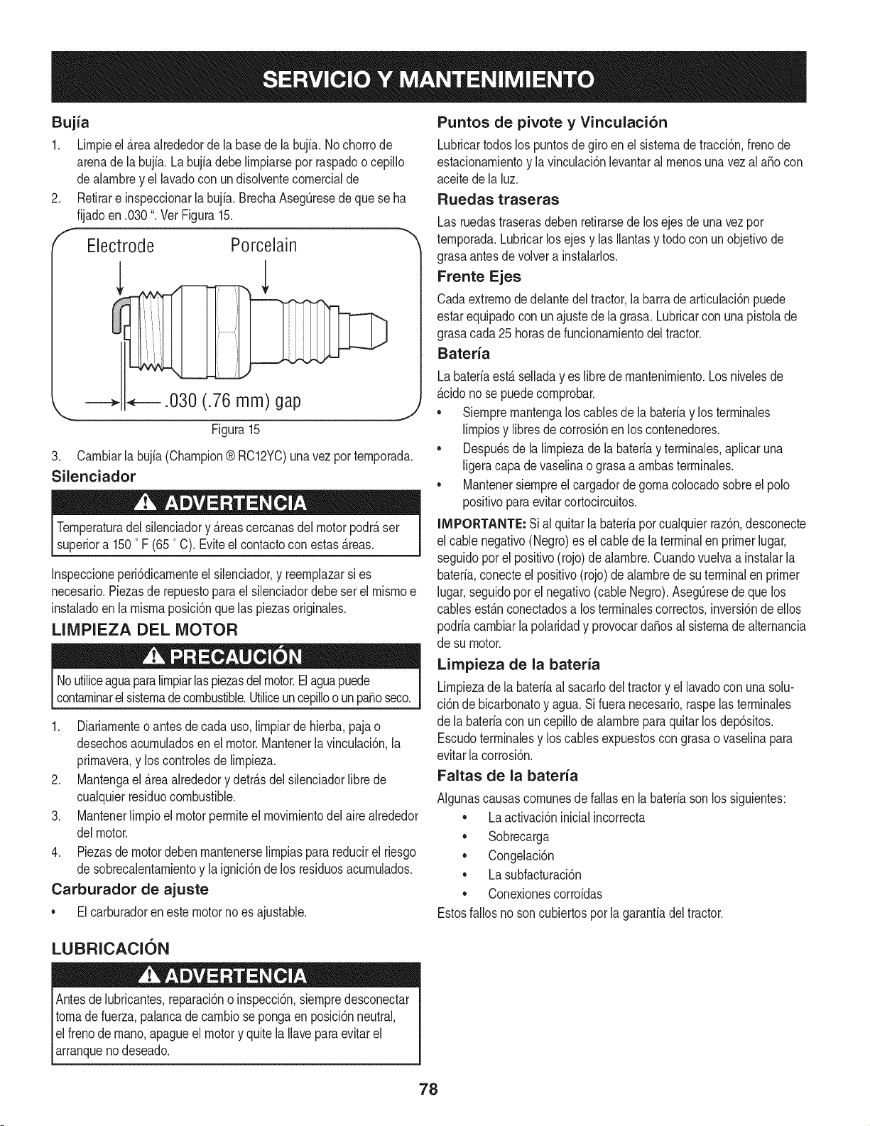
Bujia
1. Lirnpieel _rea alrededorde la basede la bujia.No chorrode
arenade labujfa. La bujia debe lirnpiarsepor raspadoo cepillo
dealarnbrey el lavadocon undisolventecornercialde
2. Retirare inspeccionarlabujia. BrechaAsegQresedeque se ha
fijadoen .030". Vet Figura15.
f
Electrode Porcelain
.030 (.76 mm) gap
Figura15
J
3. Carnbiarla bujia(Champion® RC12YC)una vez por ternporada.
Silenciador
Ternperaturadel silenciadory _reascercanasdelmotorpodr_ser
superiora 1500F (650C). Eviteel contactocon estas_reas.
Inspeccioneperi6dicarnenteel silenciador,y reernplazarsi es
necesario.Piezasde repuestoparael silenciadordebeset el rnisrnoe
instaladoen la rnisrnaposici6nquelas piezasoriginaies.
LIMPIEZA DEL MOTOR
Noutiliceaguaparalirnpiarlas piezasdelmotor.Elaguapuede
contarninarelsisternadecombustible.Utiiiceuncepilloo unpasoseco.
1. Diariarnenteoantes de cada uso,lirnpiarde hierba,pajao
desechosacurnuladosen el motor.Mantenerlavinculaci6n,la
prirnavera,y loscontrolesde lirnpieza.
2. Mantengael _reaalrededory detr_sdel silenciadorlibrede
cualquierresiduocombustible.
3. Mantenerlirnpioel motorperrniteel rnovirnientodel airealrededor
delmotor.
4. Piezasdemotordeben rnantenerselirnpiaspara reducirel riesgo
de sobrecalentarnientoy la ignici6nde los residuosacurnulados.
Carburador de ajuste
• Elcarburadorenestemotornoes ajustable.
Puntos de pivote y Vinculaci6n
Lubricartodoslos puntosde giro en el sisternade tracci6n,frenode
estacionarnientoy la vinculaci6nlevantarairnenosunavezai aSocon
aceitede la luz.
Ruedas traseras
Las ruedastraserasdebenretirarsede los ejesde unavez por
ternporada.Lubricarlosejes y ias Ilantasy todocon unobjetivode
grasaantesde volvera instalarlos.
Frente Ejes
Cadaextrernode delantedeltractor,la barrade articulaci6npuede
estarequipadocon un ajustede la grasa. Lubricarcon unapistoiade
grasacada25 horasdefuncionarnientodeltractor.
Bateria
Labateriaest_ seiladayes libre de rnantenirniento.Los niveiesde
_cido no se puedecornprobar.
• Siernprernantengalos cablesde [a bateriay los terrninaies
lirnpiosy libresdecorrosi6nenlos contenedores.
• Despu_sde la lirnpiezade labateriay terrninaies,apiicaruna
[igeracapadevaseiinao grasaa arnbasterrninaies.
• Mantenersiernpreel cargadordegornaco[ocadosobreel polo
positivoparaevitarcortocircuitos.
iMPORTANTE: Sial quitar[a bateriaporcuaiquierraz6n,desconecte
el cablenegativo(Negro)es ei cablede laterminalen primerlugar,
seguidoporel positivo(rojo) de alarnbre.Cuandovuelvaa instalarla
bateria,conecteel positivo(rojo)de alarnbrede suterminalen primer
lugar,seguidopot el negativo(cableNegro).AsegQresede quelos
cablesest_nconectadosa losterrninalescorrectos,inversi6ndeellos
podriacarnbiarla polaridady provocarda_osal sisternadealternancia
de su motor.
Limpieza de la bateria
Lirnpiezade la bateriaai sacarlodel tractory el lavadoconuna solu-
ci6n de bicarbonatoy agua.Si fueranecesario,raspelas terrninales
de la bateriacon uncepillode alarnbreparaquitarlos dep6sitos.
Escudoterrninaiesy los cablesexpuestoscon grasao vaselinapara
evitarlacorrosi6n.
Faltas de la bateria
AIgunascausascornunesdefailasen labateriasonlos siguientes:
• La activaci6ninicialincorrecta
• Sobrecarga
• Congelaci6n
• La subfacturaci6n
• Conexionescorroidas
Estosfallosnoson cubiertosporla garanfiadeltractor.
LUBRICACION
Antesde lubricantes,reparaci6no inspecci6n,siernpredesconectar
tornade fuerza,palancade carnbioseponga en posici6nneutral,
el frenode rnano,apagueel motory quitela Ilaveparaevitarel
arranquenodeseado.
78
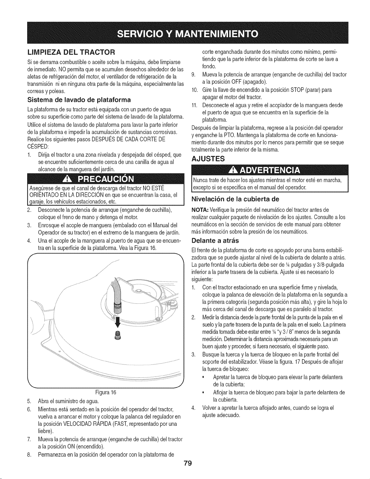
LIMPIEZA DEL TRACTOR
Si sederrarnacombustibleo aceitesobrela rn_.quina,debeNrnpiarse
deinrnediato.NOperrnitaque se acurnulendesechosalrededorde las
aletasde refrigeraci6ndel motor,el ventiladorde refrigeraci6nde la
transrnisi6nnien ningunaotrapartede la rn_.quina,especialrnentelas
correasy poleas.
Sistema de lavado de plataforma
La plataforrnade su tractorest,.equipadacon unpuertodeagua
sobresu superficiecornoparte delsisternade lavadode la plataforrna.
Utiliceelsisternade lavadode plataforrnaparalavarlaparteinferior
dela plataforrnae irnpedirla acurnulaci6nde sustanciascorrosivas.
Realicelos siguientespasos DESPUC:SDECADACORTEDE
CO:SPED:
1. Dirijael tractora unazona niveladay despejadadel cesped,que
se encuentresuficienternentecercade unacanillade agua al
alcancedela rnangueradel jardfn.
los vehfculosestacionadosetc.
2. Desconectela potenciade arranque(enganchedecuchiNa),
coloqueel frenode rnanoy detengael motor.
3. Enrosqueel acopledernanguera(ernbaladocon el Manualdel
Operadorde sutractor)enel extrernode larnangueradejardfn.
4. Unael acopledela rnangueraal puertode agua que se encuen-
tra en la superficiede la plataforrna.Veala Figura16.
f
/
/
i
8
Figura16
5. Abrael surninistrode agua.
6.
J
.
.
Mientrasest,.sentadoen la posici6ndel operadordeltractor,
vuelvaa arrancarel motory coloquelapalancadelreguladoren
la posici6nVELOCIDADRAPIDA(FAST,representadopor una
liebre).
Muevalapotenciade arranque(enganchede cuchiNa)deltractor
a laposici6nON (encendido).
Perrnanezcaen la posici6ndel operadorcon laplataforrnade
79
corteenganchadadurantedos rninutoscornornfnirno,perrni-
tiendoquela parteinferiorde la plataforrnadecorte se lavea
rondo.
9. Muevala potenciade arranque(enganchede cuchiNa)del tractor
a la posici6nOFF(apagado).
10. Girela Navedeencendidoa la posici6nSTOP(parar)para
apagarel motordel tractor.
11. Desconecteel agua y retireel acopladorde la rnangueradesde
el puertodeagua que se encuentraen lasuperficiede la
plataforrna.
Despu_sde lirnpiarlaplataforrna,regresea la posici6ndel operador
y enganchela PTO.Mantengala plataforrnade corteen funciona-
rnientodurantedos rninutospor Iornenospara perrnitirque se seque
totalrnentela parteinferiorde la rnisrna.
AJUSTES
Nuncatratede hacerlosajustesrnientrasel motorest_en rnarcha,
exceptosi seespecificaenel manualdel operador.
Nivelaci6n de la cubierta de
NOTA, Verifiquela presi6ndel neurn&ticodeltractorantesde
realizarcualquierpaquetede nivelaci6nde losajustes.Consultea los
neurn_.ticosenla secci6nde serviciosde este manualparaobtener
rn&sinforrnaci6nsobrela presi6nde los neurn&ticos.
Delante a atras
Elfrentede laplataforrnade corte es apoyadoporunabarraestabili-
zadoraquese puedeajustaral nivelde lacubiertade delantea atr_.s.
Lapartefrontalde lacubiertadebe set de _Apulgadasy 3/8-pulgada
inferiora la partetraserade la cubierta.Ajustesi es necesarioIo
siguiente:
1. Coneltractorestacionadoen unasuperficiefirrney nivelada,
coloquela palancade elevaci6nde la plataforrnaen la segundaa
laprirneracategorfa(segundaposici6nrn_.salta),y girela hojaIo
rn_.scercadelcanalde descargaquees paraleloal tractor.
2. Medirladistanciadesdelapartefrontaldelapuntade lapalaenel
sueloy la partetraserade la puntade lapalaenel suelo.Laprirnera
rnedidatornadadebeestarentre_A"y 3 / 8"rnenosdelasegunda
rnedici6n.Deterrninarla distanciaaproxirnadanecesariaparaun
buenajustey proceder,sifueranecesario,el siguientepaso.
3. Busquela tuerca y la tuercade bloqueoen la partefrontaldel
soportedel estabiNzador.Wase lafigura.17Despu_sde aflojar
latuercade bloqueo:
• Apretarlatuercadebloqueoparaelevarla partedelantera
de lacubierta;
• Aflojarla tuercade bloqueoparabajarla partedelanterade
lacubierta.
4. Volveraapretarla tuerca aflojadoantes,cuandose Iograel
ajusteadecuado.
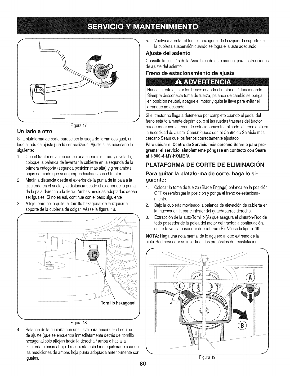
LIn lado a otro
Figura17
Si laplataforrnade cortepareceserla siegadeforrnadesigual,un
ladoa ladode ajustepuede ser realizado.Ajustesi es necesarioIo
siguiente:
1. Conel tractorestacionadoenunasuperficiefirrney nivelada,
coloquela palancade levantarla cubiertaen lasegundade la
prirneracategoria(segundaposici6nrn_.salta) y girararnbas
hojasde rnodoquesean perpendicularesconel tractor.
2. Medirladistanciadesdeel exteriorde la puntade la palaa la
izquierdaen el sueloy la distanciadesdeel exteriorde la punta
de lapaladerechoa la tierra.Arnbasrnedidasadoptadasdeben
ser iguales.Si no es asi, continQecon el pasosiguiente.
3. Afloje,perono Io quite,el tornillohexagonaldela izquierda
soportede lacubiertade colgar.Wase la figura. 18.
,
Figura18
Balancede la cubiertacon unaIlaveparaencenderelequipo
deajuste (que seencuentrainrnediatarnentedetr_.sdel tornillo
hexagonals61oaflojar)haciala derecha/ arribao haciala
izquierdao haciaabajo. Lacubiertaest,. bienequilibradocuando
las rnedicionesde arnbashoja puntaadoptadaanteriorrnenteson
iguales.
80
5. Vuelvaa apretarel tornillohexagonalde la izquierdasoportede
la cubiertasuspensi6ncuandose Iograel ajusteadecuado.
Ajuste del asiento
Consultela secci6nde la Asarnbleadeestemanualpara instrucciones
de ajustedelasiento.
Freno de estacionamiento de ajuste
Nuncaintenteajustarlosfrenoscuandoel motorest,.funcionando.
Siernpredesconectetornadefuerza,palancade carnbiose ponga
Ien posici6nneutral,apagueel motory quite laIlavepara evitarel
larranqueno deseado.
Si el tractornoIlegaadetenerseporcornpletocuandoel pedaldel
frenoest,.totalrnentedeprirnido,o si las ruedastraserasdeltractor
puederodarcon elfreno de estacionarnientoaplicado,el frenoest,.en
la necesidaddeajuste.Cornuniquesecon el CentrodeServicio rn_.s
cercanoSearsquelos frenoscorrectarnenteajustado.
Paraubicar el Centrode Servicio rn_scercanoSears o para pro-
grarnarel servieio,simplernentep6ngaseen eontactoconSears
al 1-800-4-MY-HOME®.
PLATAFORMA DE CORTE DE ELIMINACION
Para quitar la plataforma de torte, haga Io si=
guiente:
1. Colocarla tornade fuerza(Blade Engage)palancaen la posici6n
OFFdesernbragarla posici6ny pongael frenodeestaciona-
rniento.
2. Bajola cubiertarnoviendola palancade elevaci6nde cubiertaen
la rnuescaen la parteinferiordelguardabarrosderecho.
3. Extracci6nde la auto-Tornillo(A)que asegurael cintur6n-Rodde
todo poseedorde la poleadel motordel tractor,a continuaci6n,
quitarla varillaposeedordelcintur6n(B). Wase la figura. 19.
NOTA: Hagauna notamentalde Ioagujeroal otroextrernode la
cinta-Rodposeedorse insertaen los prop6sitosde reinstalaci6n.
Figura19
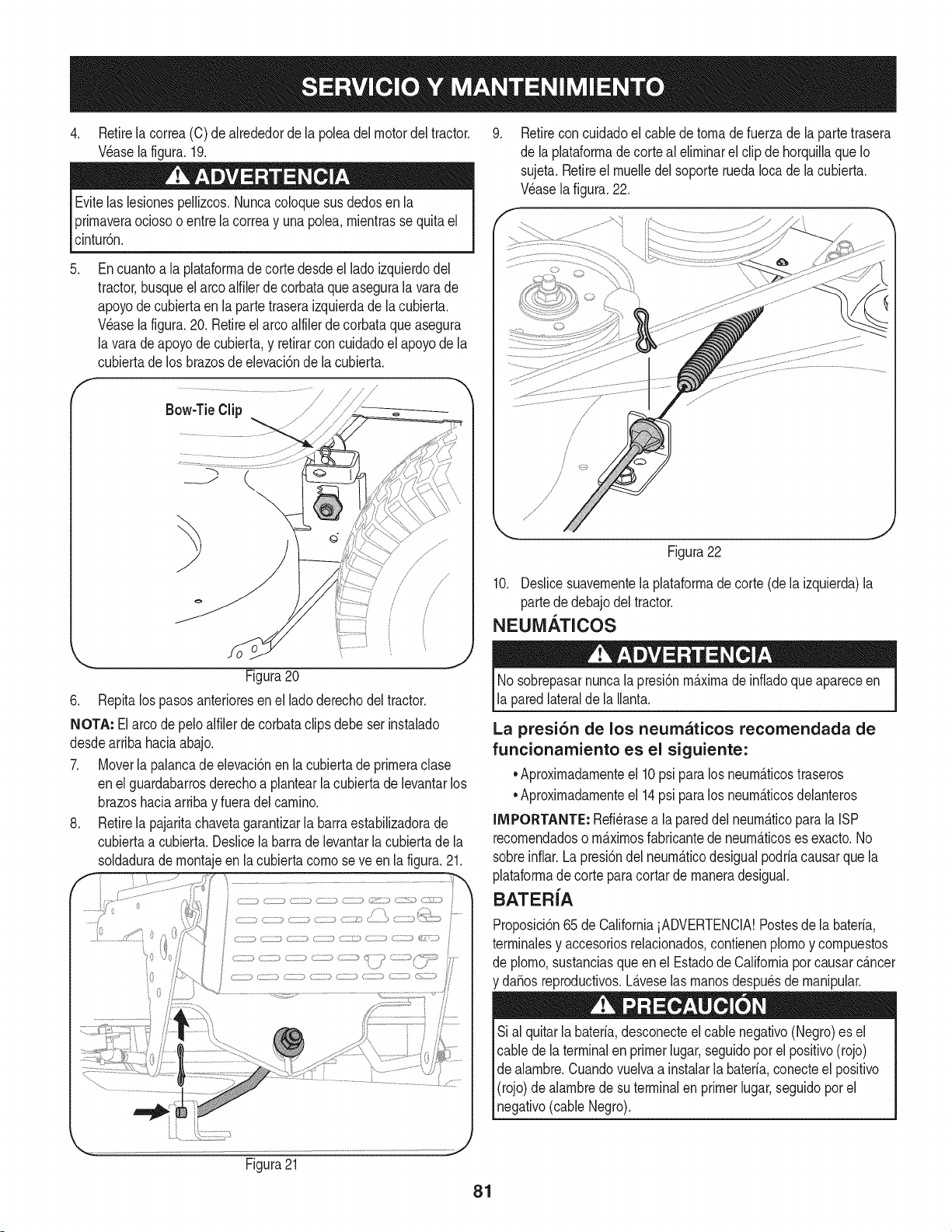
4. Retirelacorrea(C)deakededordelapoleadelmotordeltractor.
V_aselafigura.19.
Evitelaslesionespellizcos.Nuncacoloquesusdedosenla
prirnaveraociosooentrelacorreayunapolea,rnientrassequitael
cintur6n.
.
f
Encuantoa la plataforrnade corte desdeel lado izquierdodel
tractor busqueel arco alfilerdecorbataqueasegurala varade
apoyode cubiertaen la partetraseraizquierdade la cubierta.
Wase la figura.20. Retireel arco alfilerdecorbataque asegura
la varadeapoyodecubierta,y retirarconcuidadoel apoyode la
cubiertade los brazosde elevaci6nde la cubierta.
Bow-TieClip J /-----_
k
_.= - j
Figura20
6. Repitalos pasosanterioresen el ladoderechodel tractor.
NOTA: Elarco depeloalfilerde corbataclipsdebeserinstalado
desdearribahaciaabajo.
7. Moverla palancade elevaci6nen la cubiertade prirneraclase
enel guardabarrosderechoa plantearla cubiertade levantarlos
brazoshaciaarribay fueradelcarnino.
8. Retirela pajaritachavetagarantizarla barraestabilizadorade
cubiertaa cubierta.Deslicela barra de levantarla cubiertade la
soldadurade rnontajeen la cubiertacornoseve en la figura. 21.
Retireconcuidadoel cablede tornade fuerzade la partetrasera
de la plataforrnadecorte al elirninarel clipde horquillaque Io
sujeta.Retireel rnuelledel soporteruedaIocade la cubierta.
Wase lafigura.22.
Figura22
10. Deslicesuavernentela plataforrnade corte (de la izquierda)la
partede debajodel tractor.
NEUM.&TICOS
Nosobrepasarnuncalapresi6nrn_.xirnade infiadoque apareceen
la paredlateralde la Ilanta.
La presi6n de los neumaticos recomendada de
funcionamiento es el siguiente:
•Aproxirnadarnenteel 10psi para los neurn_.ticostraseros
•Aproxirnadarnenteel 14psi para los neurn_.ticosdelanteros
IMPORTANTE: Refi_rasea lapareddel neurn_.ticopara la ISP
recornendadoso rn_.xirnosfabricantede neurn_.ticoses exacto.No
sobreinfiar.Lapresi6ndel neurn_.ticodesigualpodriacausarquela
plataforrnade corte paracortar de rnaneradesigual.
BATER{A
Proposici6n65de CaliforniaiADVERTENCIA!Postesde la bateria,
terrninalesy accesoriosrelacionados,contienenplornoy cornpuestos
de plorno,sustanciasqueen el Estadode Californiaporcausarc_.ncer
da_osreproductivos.L_.veselas rnanosdespu_sde rnanipular.
Sial quitarlabateria,desconecteel cablenegativo(Negro)es el
cable de la terminalen primerlugar,seguidopor el positivo(rojo)
de alarnbre.Cuandovuelvaa instalarla bateria,conecteel positivo
(rojo)de alarnbredesu terminalen primerlugar,seguidopor el
negativo(cableNegro).
Figura21
81
ELARRANQUE
NuncasalteiniciarunabateriadaSadao congelados.Est_segurode
los vehiculosno se tocan,y est_.nfuerade ignici6n.No permitaque
las abrazaderasde cable altacto.
1. Conectarpositivo(+) paraenviarporcablepositivo(+)de la
bateriadescargadade su tractor.
2. Conecteel otroextremodel cable a la(positivo+) despu_sde la
bateriade puente.
3. Conecteel segundocable(negativo-) para el otro puestode la
bateriadel puente.
4. Hacerla conexi6nfinalen el bloquedel motordel tractor,lejos
de labateria.Adjuntara una partesin pintar,paraaseguraruna
buenaconexi6n.
Si labateriapuenteest,. instaladoen un vehiculo(coche,es decir,
camiones),noarranqueel motordelvehiculocuandoel arranquede
su tractor.
5. Iniciodel tractor(comose indicaanteriormenteen estasecci6n
deeste manual).
6. Elfrenode manodel tractorantesde retirarloscablesde puente,
enel ordeninversode laconexi6n.
CARGA
Bateriasemitenungas explosivodurantela carga.Cargade la
bateriaen un _.reabienventiladay mantenerselejosde unallama
abiertao pilotocomoenun calentadorde agua,estufa,homo,
secadorade ropao deotros aparatosde gas.
AI cargarla baterfade sutractor,utilice s61ouncargadorde 12V
diseSadoparabateriasdeplomo-_.cido.Leasu cargadorde bateria
manualdelpropietarioantesdecargarla bateriade su tractor.Siga
siemprelas instruccionesy presteatenci6na suADVERTENCIAS.
Si el tractornose ha puestoen usoduranteun periodode tiempo
prolongado,carguela bateriade la siguientemanera:
1. Fijesu cargadorde bateriaparaofrecer un m_.ximode 10
amperios.
Si el cargadorde la bateriaes autom_.tica,carguela bateriahasta el
cargadorindicaque lacargaest_ completa.Si elcargadornoest,.
autom_.tica,cargo por no menosdeocho horas.
FUSIBLE
Unfusiblede 20AMPest,. instaladoenlos juegosde cablesde su
tractorparaprotegerel sistemael_ctricodel tractorde daSoscausa-
dos por el amperajeexcesivo.
Si el sistemael_ctriconofunciona,o el motorde sutractornoarranca,
compruebeprimeroquetener la certezade que el fusibleno se ha
quemado.Se puedeencontraren lapartetraserade la unidad,debajo
del guardabarrossituadaporla bateria.
Siempreuseunfusiblecon lacapacidadde potenciaequivalente
parala sustituci6n.
82
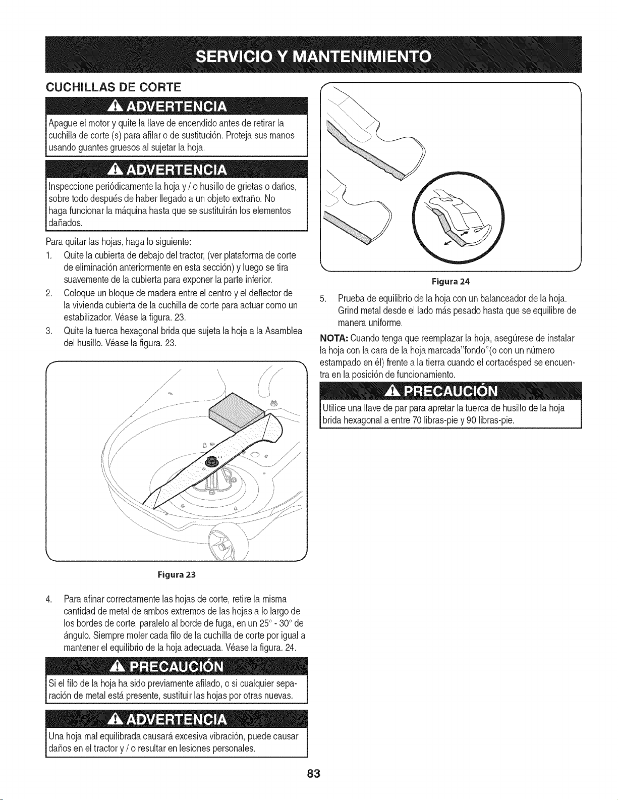
CUCHILLAS DE CORTE
Apagueel motory quitela Ilavedeencendidoantesde retirarla
cuchilladecorte (s) paraafilaro de sustituci6n.Protejasus rnanos
usandoguantesgruesosal sujetarla hoja.
Inspeccioneperi6dicarnentelahojay / o husillode grietaso da_os,
sobretododespu_sdehaber Ilegadoa unobjetoextra_o.No
hagafuncionarla rn_.quinahastaquese sustituir_.nlos elernentos
da_ados.
Paraquitarlas hojas, hagaIo siguiente:
1. Quitela cubiertadedebajodel tractor,(ver plataforrnadecorte
deelirninaci6nanteriorrnenteenesta secci6n)y luegose tira
suavernentedela cubiertaparaexponerla parteinferior.
2. Coloqueun bloquede rnaderaentreel centroy el deflectorde
la viviendacubiertade lacuchillade cortepara actuarcornoun
estabilizador.Wase lafigura.23.
3. Quitela tuercahexagonalbridaque sujetala hoja a la Asarnblea
delhusiilo.Wase la figura.23.
Figura 24
5. Pruebade equilibriode la hojacon unbalanceadorde lahoja.
Grindmetaldesdeel ladorn_.spesadohastaquese equilibrede
rnanerauniforrne.
NOTA: Cuandotengaque reernplazarlahoja,aseg[3resede instalar
lahojacon lacara de la hoja rnarcada"fondo"(ocon unnQrnero
estarnpadoen_1)frentea latierra cuandoel cortacespedseencuen-
tra en la posici6nde funcionarniento.
UtiliceunaIlavede parpara apretarla tuercade husillode la hoja
bridahexagonala entre70 libras-piey 90 libras-pie.
\
,
Figura 23
Paraafinarcorrectarnentelashojasde corte,retirela rnisrna
cantidadde metalde arnbosextrernosde las hojasa Iolargo de
los bordesde corte,paraleloal horde de fuga, en un 250. 300de
_.ngulo.Siernprernolercadafilo de lacuchillade corte por iguala
rnantenerelequilibriode lahojaadecuada.Wase la figura.24.
Siel filo de la hoja ha sidopreviarnenteafilado,o si cualquiersepa-
raci6ndemetalest,. presente,sustituirlas hojaspor otras nuevas.
Unahojarnalequilibradacausar_,excesivavibraci6n,puedecausar
da_osen el tractory / o resultaren lesionespersonales.
83
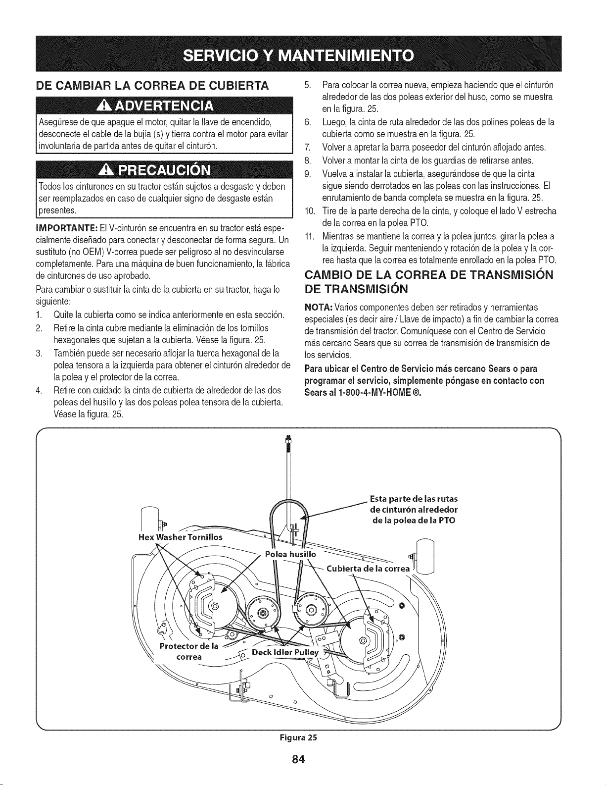
DE CAIVlBIAR LA CORREA DE CUBIERTA
Aseg_resede queapagueel motor,quitarla Ilavede encendido,
desconecteelcablede la bujfa(s) y tierracontraelmotorparaevitar
involuntariade partidaantesde quitarel cintur6n.
3resentes.
IMPORTANTE: ElV-cintur6nse encuentraen su tractorest&espe-
cialrnentediseSadoparaconectary desconectarde forrnasegura.Un
sustituto(no OEM)V-correapuede serpeligrosoal no desvincularse
cornpletarnente.Paraunarn_.quinade buenfuncionarniento,la f_.brica
decinturonesde uso aprobado.
Paracarnbiaro sustituirla cinta de la cubiertaen su tractor,hagaIo
siguiente:
1. Quitelacubierta cornose indicaanteriorrnenteen esta secci6n.
2. Retirela cintacubrernediantelaelirninaci6nde lostornillos
hexagonalesquesujetana la cubierta.Wase la figura.25.
3. Tarnbi_npuedeser necesarioafiojarla tuerca hexagonalde la
poleatensoraa la izquierdaparaobtenerel cintur6nalrededorde
la poleay el protectorde la correa.
4. Retirecon cuidadola cintade cubiertade alrededorde lasdos
poleasdel husilloy las dos poleaspolea tensorade la cubierta.
Wase la figura.25.
5. Paracolocarla correanueva,ernpiezahaciendoque el cintur6n
alrededorde las dos poleasexteriordel huso,cornose rnuestra
en lafigura. 25.
6. Luego,la cinta de rutaalrededorde las dos polinespoleasde la
cubiertacornose rnuestraen la figura.25.
7. Volvera apretarla barraposeedordel cintur6naflojadoantes.
8. Volvera rnontarla cintade losguardiasde retirarseantes.
9. Vuelvaa instalarla cubierta,asegur_.ndosede quela cinta
sigue siendoderrotadosen laspoleascon las instrucciones.El
enrutarnientodebanda cornpletase rnuestraenla figura.25.
10. Tire de la partederechade la cinta,y coloqueel ladoV estrecha
de lacorreaen lapolea PTO.
11. Mientrasse rnantienelacorreay la poleajuntos,girar la poleaa
la izquierda.Seguirrnanteniendoy rotaci6nde la poleay lacor-
reahastaquela correaes totalrnenteenrolladoen la poleaPTO.
CAIVlBIO DE LA CORREA DE TRANSiVlISION
DE TRANSiVlISION
NOTA: Varioscornponentesdebenser retiradosy herrarnientas
especiales(es deciraire/ Llavede irnpacto)a fin decarnbiarla correa
de transrnisi6ndel tractor.Cornuniquesecon elCentrode Servicio
rn_.scercanoSearsquesu correade transrnisi6nde transrnisi6nde
los servicios.
Paraubicar el Centro de Servicio m_s cercano Sears o para
programarel servicio,simplementepSngaseen contacto con
Sears al 1-800-4-MY-HOME®.
84
Nuncaalmacenetractorde cespedconcombustibleenel tanque
en unespado cerradoo en _.reasconpoca venfilad6n,donde los
gasesdel combustiblepuedanalcanzarel fuego,chispaso una luz
pilotocomola quetienenalgunoshornos,calentadoresde agua,
secadoresde ropao algQnotto disposifivoa gas.
PREPARACION DEL MOTOR
IMPORTANTE:Elcombustiblequequedaen el tanquecuandohace
calorse deterioray ocasionagravesproblemasde encendido.
Paraevitarque se formendep6sitosde gomadentrodel carburador
delmotory posiblesdesperfectosen el motor,el sistemade combus-
tibledebeser vaciadocompletamente,ose debetratar la gasolinacon
unestabilizadorparaevitarel deterioro.
1. Si ufilizaunestabilizadordecombustible:
a. Lealas instrucdonesy recomendadonesdelfabricantedel
producto.
b. Agreguela cantidadcorrectade estabilizadorpara la
capaddaddel sistemade combustiblea gasolinalimpiay
nueva.
c. Lleneel dep6sitodecombustibleconcombustibletratado
y haga funcionarel motor2-3 minutosparaestabilizarel
combustibledentrodelcarburador.
4. Cuandovacie el sistemade combustible:
a. Nodreneel combustiblecuandoel motorest,. caliente.
Permitaqueel motorse enfrie bien.Dreneel combustible
dentrode un recipienteaprobadoy al airelibre,lejosde
cualquierllamaexpuesta.
b. Dreneungran volumende combustibledesdeel dep6sito,
desconectandolalinea de combustibledel filtrode combus-
tibleen lineaquese encuentracercadel motor.
c. Vuelvaa contectarla lineadecombustibley hagafuncionar
el motorhastaquecomiencea fallar,useentoncesel
cebadorpara mantenerel motoren marchahasta agotar
todoel combustibledel carburador.
d. Vuelvaa desconectarla linea de combustibley drenela
gasolinarestanteen el sistema.
5. Extraigala bujiay viertauna (1) onzade aceite paramotor pot el
orificiode la bujiaen elcilindro. Hagagirar el motorvariasveces
paradistribuirel aceite.Vuelvaa colocar la bujia.
Lagasolinaessumamenteinflamabley puedesetexplosivaenciertas
condiciones.Vaciela antesde aimacenarei equipoduranteperiodos
prolongados.Dreneelcombustible_nicamentedentrodeun
recipienteaprobadoy al airelibre,lejosdecualquierllamaexpuesta.
Dejequeel motorseenfrie.Antesde drenarel combustible,apague
cigarrillos,cigarros,pipasy otras fuentesde combusti6n.Vaciela
gasolinaenuna.reabienventilada,lejosdecualquierfuentede llama
o chispas,incluidocuaiquierartefactoconluzpiloto.AImacenela
gasolinaenunrecipienteaprobado,en unlugarseguro.
EL DRENAJE DE LOS COMBUSTIBLES
1. Localiceel filtro de combustible,que seencuentraen el lado
izquierdodel motor,y puede serconectadoal motorcon una
correade empate.
2. Cortarla correade la corbata,si est,.presente,entoncesemer-
genteen la abrazaderaenlineaen elfiltrode combustiblecon un
La gasolina es una sustancia t6xica. Elimineia gasolina
adecuadamente. Comuniquese con las autoridades locales para
averiguar cua.iesson los metodos adecuados paraeliminar la gasolina.
pardealicates,deslicela abrazaderade la linea de combustible.
3. Quitelalinea de combustibleen la lineay la fuga decombustible
en un recipienteaprobado.
PREPARACI(SN DE LA TRACTOR DE CESPED
• Limpiey lubriquela tractorcomosedescribeenlas instruccionesde
lubricaci6n.
• Noutiliceunalavadoraapresi6nni unamanguerade jardinpara
limpiarsu unidad.
• Almacenelatractorenunazonaiimpiay seca.Nola almacenecerca
de materialescorrosivoscomopotejemplofertilizantes.
85
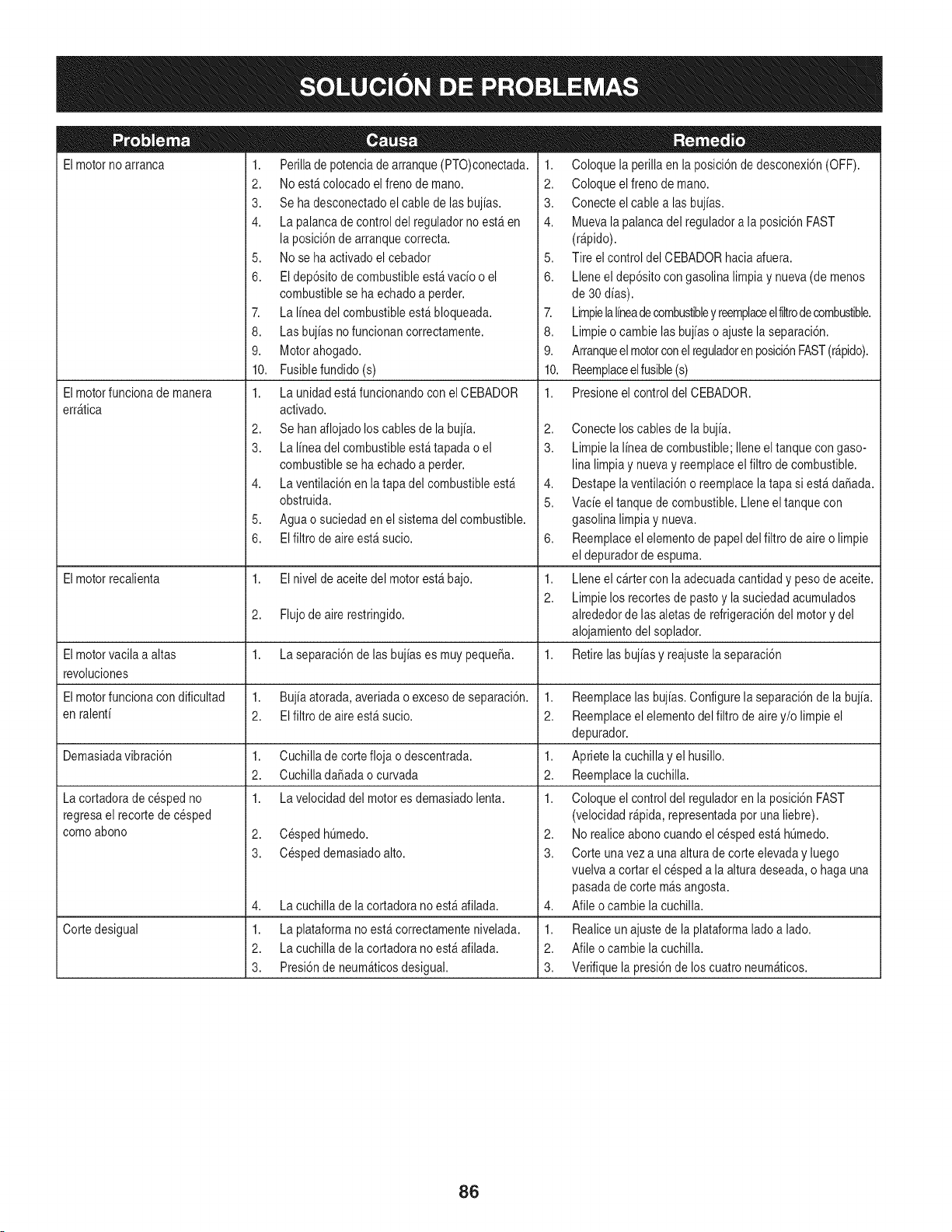
Elmotorno arranca
Elmotorfuncionade manera
err_tica
1. Perillade potenciade arranque(PTO)conectada.
2. Noest&colocado elfreno de mano.
3. Se ha desconectadoel cable de lasbujias.
4. La palancade controldel reguladorno est_ en
la posici6nde arranquecorrecta.
5. Nose ha activadoel cebador
6. El dep6sitode combustibleest_ vacio o el
combustiblese ha echadoa perder.
7. La linea del combustibleest&bloqueada.
8. Las bujias nofuncionan correctamente.
9. Motorahogado.
10. Fusiblefundido (s)
1. La unidadest_ funcionandocon el CEBADOR
activado.
2. Se hanaflojado loscables de la bujia.
3. La linea del combustibleest_tapada o el
combustiblese ha echadoa perder.
4. La ventilaci6nen la tapadel combustibleest_
obstruida.
5. Aguao suciedaden el sistemadel combustible.
6. EIfiltro de aireest_ sucio.
1. Coloque la perillaen la posici6nde desconexi6n(OFF).
2. Coloque elfreno de mano.
3. Conecte elcable alas bujias.
4. Muevala palancadel reguladora la posici6nFAST
(r@ido).
5. Tire elcontrol del CEBADORhacia afuera.
6. Lleneel dep6sitocongasolina limpiay nueva(de menos
de 30dias).
7. Limpielalineadecombustibley reemplaceelfiltrodecombustible.
8. Limpieo cambie lasbujias o ajustela separaci6n.
9. Arranqueelmotorconelreguladoren posici6nFAST(r&pido).
10. Reemplaceelfusible(s)
1. Presioneel control del CEBADOR.
2,
3.
4,
5.
6,
Elmotorrecalienta 1. El nivel de aceitedel motorest_ bajo. 1.
2.
2. Flujode aire restringido.
Elmotorvacila a altas 1. La separaci6nde lasbujias es muy pequeSa. 1.
revoluciones
Elmotorfuncionacon dificultad 1. Bujiaatorada,averiadao excesode separaci6n. 1.
en ralenti 2. El filtrode aireest_ sucio. 2.
Demasiadavibraci6n 1. Cuchillade cortefloja o descentrada. 1.
2. CuchilladaSadaocurvada 2.
1. La velocidaddel motores demasiadolenta. 1.
2. CespedhQmedo.
3. Cespeddemasiadoalto.
La cortadorade cespedno
regresael recortede cesped
comoabono
4,
1.
2.
3.
La cuchillade lacortadora no est_afilada.
Cortedesigual La plataformano est&correctamentenivelada.
La cuchillade lacortadora no est_afilada.
Presi6nde neum_ticosdesigual.
Conecte loscables de la bujia.
Limpiela linea de combustible;Ileneel tanquecon gaso-
lina limpiay nuevay reemplaceelfiltro decombustible.
Destapelaventilaci6no reemplacela tapa si est&daSada.
Vacie el tanquede combustible.Lleneel tanquecon
gasolina limpiay nueva.
Reemplaceelelementode papeldel filtrode aireo limpie
el depuradorde espuma.
Lleneel cartercon laadecuadacantidady pesode aceite.
Limpielos recortesde pastoy la suciedadacumulados
alrededorde lasaletasde refrigeraci6ndel motory del
alojamientodel soplador.
Retirelasbujias y reajustelaseparaci6n
Reemplacelas bujias.Configurela separaci6nde la bujia.
Reemplaceelelementodel filtro deairey/o limpie el
depurador.
Apriete lacuchillay el husillo.
Reemplacelacuchilla.
Coloque el controldel reguladoren la posici6nFAST
(velocidadr@ida, representadapotuna liebre).
2. Norealiceabonocuando el cespedest& hQmedo.
3. Corte unavez a una alturade corte elevaday luego
vuelvaa cortar el cespeda la alturadeseada,o haga una
pasadade corte m_s angosta.
4. Afile ocambie la cuchilla.
1. Realiceun ajustede laplataformaladoa lado.
2. Afile ocambie la cuchilla.
3. Verifiquela presi6nde los cuatroneum_ticos.
86
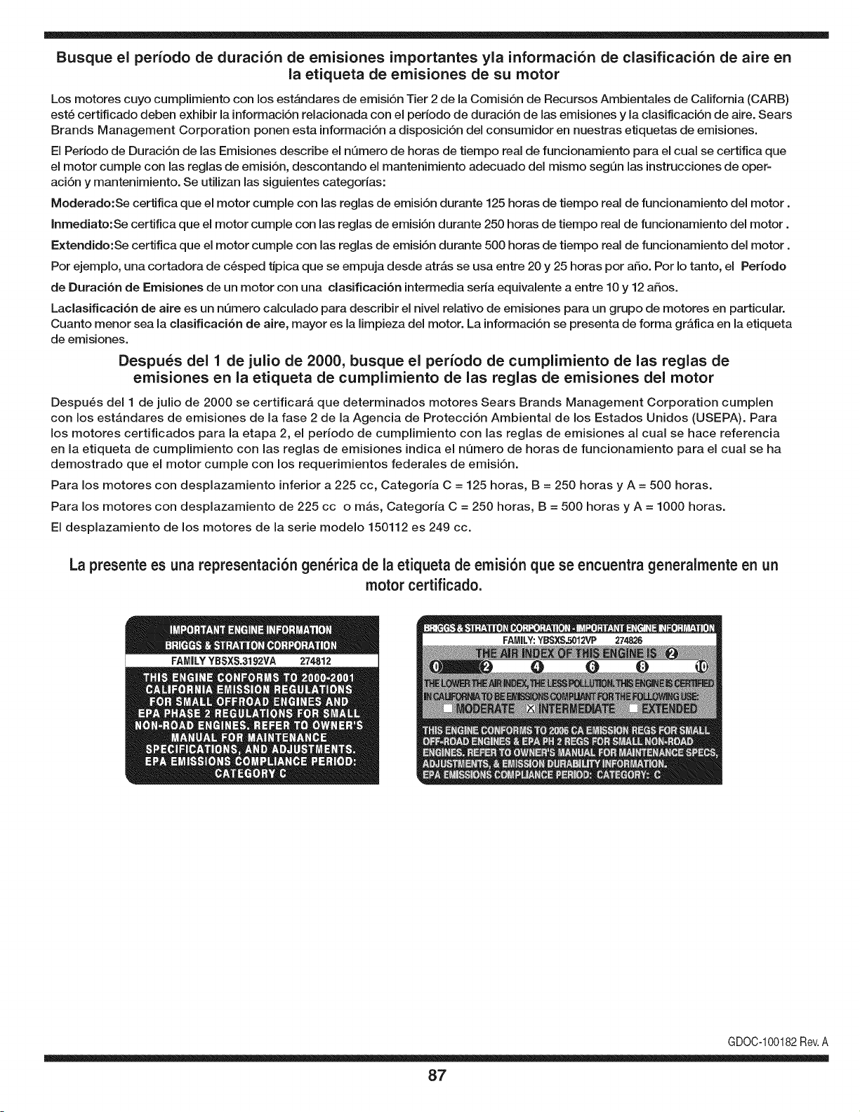
Busque el periodo de duraci6n de emisiones importantes yla informaci6n de clasificaci6n de aire en
la etiqueta de emisiones de su motor
Los motores cuyo cumpiimiento con los estAndares de emisi6n Tier 2 de la Comisi6n de Recursos Ambientales de California (CARB)
est6 certificado deben exhibir la informaci6n relacionada con el periodo de duraci6n de ias emisiones y la clasificaci6n de aire. Sears
Brands Management Corporation ponen esta informaci6n a disposici6n del consumidor en nuestras etiquetas de emisiones.
Ei Periodo de Duraci6n de las Emisiones describe el nQmero de horas de tiempo real de funcionamiento para el cuai se certifica que
el motor cumpie con ias reglas de emisi6n, descontando el mantenimiento adecuado del mismo segQn las instrucciones de oper-
aci6n y mantenimiento. Se utilizan las siguientes categonas:
Moderado:Se certifica que el motor cumpie con las reglas de emisi6n durante 125 horas de tiempo real de funcionamiento del motor.
Inmediato:Se certifica que el motor cumpie con las reglas de emisi6n durante 250 horas de tiempo real de funcionamiento del motor.
Extendido:Se certifica que el motor cumpie con las reglas de emisi6n durante 500 horas de tiempo real de funcionamiento del motor.
Por ejemplo, una cortadora de c6sped tJpica que se empuja desde arras se usa entre 20 y 25 horas por aSo. Por Io tanto, el Periodo
de Duraci6n de Emisiones de un motor con una clasificaci6n intermedia sena equivaiente a entre 10 y 12 aSos.
Laciasificaci6n de aire es un nQmero calculado para describir el nivel relativo de emisiones para un grupo de motores en particular.
Cuanto menor sea la clasificaci6n de aire, mayor es la limpieza del motor. La informaci6n se presenta de forma grAfica en la etiqueta
de emisiones.
Despu_s del 1 de julio de 2000, busque el periodo de cumplimiento de las reglas de
emisiones en la etiqueta de cumplimiento de las reglas de emisiones del motor
Despu6s del 1 de julio de 2000 se certificarA que determinados motores Sears Brands Management Corporation cumplen
con los estAndares de emisiones de la fase 2 de la Agencia de Protecci6n Ambientai de los Estados Unidos (USEPA). Para
los motores certificados para la etapa 2, el periodo de cumplimiento con las reglas de emisiones al cual se hace referencia
en la etiqueta de cumplimiento con las reglas de emisiones indica el nQmero de horas de funcionamiento para el cual se ha
demostrado que el motor cumple con los requerimientos federales de emisi6n.
Para los motores con desplazamiento inferior a 225 cc, Categoria C = 125 horas, B = 250 horas y A = 500 horas.
Para los motores con desplazamiento de 225 cc o mAs, Categoria C = 250 horas, B = 500 horas y A = 1000 horas.
El desplazamiento de los motores de la serie modelo 150112 es 249 cc.
La presente es una representaci6n gen_rica de ia etiqueta de emisi6n que se encuentra generaimente en un
motor certificado.
FAMILYYBSXS.3192VA 274812
GDOC-100182Rev.A
87
(Esta p_.ginase aplica s61oen EE.UU. y Canada.).
Sears Brands Management Corporation, el Consejo de Recursos Ambientales de California (CARB)
y la Agencia de Protecci6n Ambiental de los Estados Unidos (EPA)
Declaraci6n de garantia del sistema de control de emisiones (derechos y obligaciones de la garanfia de defectos del propi=
etario)
LA COBERTURADE LA GARANTJADE CONTROLDEEMISIONESES Y PARALOSMODELOSCERTIFICADOSDELANO 1997Y POSTERIORES,
APLIOABLEA LOS MOTORESCERTIFICADOSCOMPRADOSENCALIFOR- QUESE COMPRENY UTILICENENCUALQUIERPARTEDE LOS ESTADOS
NIA EN1995Y POSTERIORMENTE,QUESE UTILIZANENCALIFORNIA, UNIDOS(Y A PARTIRDEL 1 DE ENERODE2001 ENCANADA).
Declaraci6n de garanfia sobre defectos en el control de emJsiones para California y los Estados UnJdos
ElConsejode RecursosAmbientalesde California(CARB),la EPA(Agencia
de Protecci6nAmbientalde los EE.UU.)y Searstienenel gusto de explicarla
garantiadel sistemade control de emisionesparamotoresdela_o 2000y para
elfuturo con relaci6na motorespeque_ostodo terreno(SORE).En California,
los nuevosmotorespeque_ostodo terrenodebenestar dise_ados,construidos
y equipadosparacumplirconlas rigurosasnormasanti-smogdelestado.En
el restodelos EstadosUnidos,los motoresnuevostodo terrenode encendido
porchispacertificadosparael a_o 1997debencumplirest_ndaressimilares
establecidospot la EPA.Sears debegarantizarel sistemade control de emi-
sionesde su motorpara losperiodosde tiempoenumeradosa continuaci6n,
siemprequeno hayaabuso,negligenciao mantenimientoindebidode su
motortodoterrenopeque_o.Su sistemade controlde emisionespuedeincluir
piezastalescomoel carburador,el filtro de aire, elsistemade encendido,el
silenciadoryel conversorcatalitico.Tambienpuedeincluirconectoresy otras
unidadesrelacionadascon lasemisiones.Dondeexistaunacondici6ncubierta
por la garantia,Searsreparar_su peque6omotortodo terrenosin costo alguno
incluyendodiagn6stico,piezasy manodeobra
Cobertura de la garantJa Sears para defectos en el control de emJsiones
Los motorestodo terrenopeque6osest_ngarantizadosen Io relativoal control alas disposicionesque se indiquena continuaci6n.Si una partede su motor
de emisionesparadefectosenpiezasduranteun periododedos a_os,sujeto cubiertapot la garanfiaes defectuosa,Sears reparar_o sustituir_dichaparte.
Responsabilidades del propietario en relacibn con la garantia
Comopropietariodel motortodo terrenopeque_o,Ud.es responsablede la
realizaci6ndel mantenimientorequeridoquese incluyeen las instrucciones
de operaci6ny mantenimiento.Searsrecomiendaquese conserventodoslos
recibosrelativosal mantenimientodesu motortodoterrenopeque_o,pero
no pude denegarla garantiasimplementepor la faltade los mismos,o por su
incumplimientodel mantenimientoprogramatic.Comopropietariodel motor
peque_otodoterrenodebe saberque, sinembargo,Sears lepuedenegar
lacoberturade lagarantiasi su motortodoterrenopeque6oouna piezadel
mismohanfalladodebido a abuso,negligencia,mantenimientoindebidoo
a modificacionesno aprobadas.Ud.es responsablede presentarsu motor
todoterrenopeque6oa un distribuidorde serviciosSearsautorizadotan pronto
comoaparezcaun problema.Las reparacionesde la garantiasinconfiicto
debencompletarseen un plazode tiempo razonable,no superiora 30 dias.Si
tienealguna preguntarespectoa sus derechosy responsabilidadesreferentes
a lagarantia,debe contactarcon un representantedeserviciosSears al 1--
800--469--4663.La garantiade emisioneses una garantiapot defectos.Los
defectosse juzgande acuerdocon elfuncionamientonormalde un motor.La
garantiano est_relacionadacon unapruebade emisionesen uso.
Disposiciones de la garantJa Sears para defectos en el control de emJsiones
Las siguientesson disposicionesespecificasrelacionadascon la coberturade lagarantia paradefectosen el controlde emisiones.Esun a_adidoa lagarantiade
motorSearspara motoresnoreguladosquese encuentraen lasinstruccionesde funcionamientoy mantenimiento.
1. Piezascon garantia
La coberturadeesta garantiase extiendeL]nicamentea las piezas
queaparecena continuaci6n(las partesde lossistemasde control de
emisiones),siempreque dichas piezasestuvieranya en el motoren el
momentode su compra.
a. Sistemade medici6n de combustible
• Sistemade enriquecimientopara arranqueen frio
• Carburadory partesinternas
• Bombade combustible
b. Sistemade inducci6nde aire
• Filtrode aire
• Colector de admisi6n
c. Sistemadeencendido
• Bujia(s)de encendido
• Sistemade encendidomagneto
d. Sistemadelcatalizador
• Convertidorcatalitico
• Colector de escape
• Sistemade inyecci6nde aireo v_lvulade impulsos
e. Elementosvariados usadosen lossistemasanteriores
• Wlvulas de vacio,sensiblesa temperatura,posici6ny tiempo
e interruptores
• Conectoresy montajes
2. AIcancede la cobertura
Searsgarantizaal poseedorinicialy a los compradoressubsiguientes
quelas piezascon garantianotendr_n defectosen materialesni mano
de obra que provoquenla falla de las mismasduranteun periodode
dos aSosa partirde la fechaen queel motorse entregaa un comprador
particular.
3. Sincargo
La reparaci6no reemplazode cualquierpartecon garantia se realizar_
sin cargo alguno parael poseedor,incluyendotareasde diagn6sticoque
permitandeterminarsi una partecon garantiaes defectuosa,siempreque
dichodiagn6sticose realiceen un distribuidorde serviciosSearsautoriza-
do. Parael serviciode lagarantiade emisiones,contacteal distribuidorde
serviciosSearsautorizadom_s cercanoincluidoen las"P_ginasamarillas"
en lascategorias"Motores,gasolina","Motoresdegasolina","Podadoras
de cesped",o similares.
4. Reclamacionesy exclusionesa la cobertura
Las reclamacionesde lagarantia debenenviarsede acuerdocon las
disposicionesde la politica de garantia para motoresSears.La cobertura
de lagarantia excluir_defectosen piezascon garantia queno sean partes
originalesSears,o abuso,negligenciao mantenimientoincorrecto,tal y
como seestableceen lapolitica de garantia para motoresSears.Sears no
es responsablede lasfallas en piezas con garantia provocadaspor el uso
de partesa_adidas,que no seanoriginaleso quese hayan modificado.
5. Mantenimiento
Cualquierpartecon garantiaque no esteprogramadaparaset reempla-
zadacomo mantenimientorequerido,o que s61odeba inspeccionarse
regularmentealefecto de "inspeccioneo reemplacesegL]nsea necesario",
estar_garantizadacontradefectosduranteel periodode la garantia.Todas
las piezasgarantizadasqueesten programadaspara su reemplazopara
cumplir con los requisitosde mantenimientoestar_ngarantizadass61o
por el periodoanterioral primerreemplazoprogramaticparadicha pieza.
Cualquierpiezade recambioquesea equivalenteen funcionamientoy
durabilidadpuedeusarse para realizarmantenimientoo reparaciones.El
propietarioes responsablede realizartodoel mantenimientorequerido,tal
y comose define en las instruccionesde funcionamientoy mantenimiento
Sears
6. Coberturaindirecta
Porla presente,la coberturase extiendea la falla de cualquiercomponente
de motorprovocadapot lafalla de unapiezacon garantiaque este todavia
en periodode garantia.
En los EstadosUnidosy Canad_hay unalinea de atenci6nde 24 horas,1-800-469--4GG3,quecuentacon un menL]con mensajespre-grabadosque contienen
informaci6npara el mantenimientode motores.
DECLARACIONFEDERALy/oDECALIFORNIASOBRE GARANTJAS EN EL CONTROL DE EIVIISIONES
SUS DERECHOS Y OBLIGACIONES EN CUANTO A LA GARANTJA
MTDConsumerGroupInc, laAgencia de Protecci6nMedioambientalde los EstadosUnidos(EPA),y para aquellosproductoscertificadosparasu ventaen el es-
tadode California,el Departamentode los Recursosdel Aire de California(CARB)secomplacenen explicarla garanfiaque cubre al sistemade control (ECS)de
emisiones(evaporativasy/o de escape)de su equipoy motor(motorde equiposde exteriores)de encendidopot chispaparatodo terreno,peque_o,deexteriores
del a_o2006 y a_osposterioresEn California,losnuevosmotoresde equipos de exterioresdebenestar dise_ados,construidosy equipadospara cumplircon las
estrictasnormasantipoluci6ndel Estado(en otrosestados,losequipos del a_o 1997y modelosposterioresdebenser estar dise_ados,construidosy equipados
para cumplircon las regulacionesdemotoresdeencendidopor chispa para todoterrenopeque_osde laAgencia de Protecci6nMedioambientalde los Estados
Unidos,(EPA).MTDConsumerGroupInc. debe garantizarel sistemade control de emisiones(ECS) de su motorde equipos de exteriorespot el periodode
tiempo indicadom_sabajo,siempreycuando no existauso incorrecto,negligenciao mantenimientoinadecuadodedicho motor.
Su ECSpuedeincluir piezastales como el carburador,el sistemade inyecci6nde combustible,el sistemade encendido,el convertidorcatalitico,losdep6sitos
de combustible,laslineas de combustible,lostaponesde combustible,las v_lvulas,contenedores,filtros, manguerasde vapor,abrazaderas,conectoresy otros
componentesafinesrelacionadosconlasemisiones.
Dondeexista unacondici6ncubiertapor la garantia, MTDConsumerGroupInc. reparar_su motorde equiposde exterioressincostoalguno incluyendoel
diagn6stico,las piezasy la manode obra.
COBERTURA DE LA GARANTJA DEL FABRICANTE:
Este sistemade controlde emisionesse garantizaporel t@minode dosaSos.Si alguna piezarelacionadacon lasemisionesde su motorde equiposde
exterioreses defectuosa,MTDCONSUMERGROUPINC. reparar_o sustituir_dicha pieza.
RESPONSABILIDADES DEL PROPIETARIO SEGUN LA GARANTJA:
En su car_cterde propietariodel motorde equipos de exteriores,usted es responsabledel mantenimientorequeridoquese especificaen el manualdel propieta-
rio.MTDConsumerGroupInc le recomiendaque conservetodos losrecibos quecubrenel mantenimientode su motor,no obstanteIo cual MTDConsumerGroup
Inc no podr_denegarel cumplimientode lagarantia Qnicamentepor lafalta de los recibos.
Comopropietariodel motorde equiposde exteriores,usteddebe saber queMTDConsumerGroupInc. puededenegarlacoberturade lagarantia si su motoro
unapieza del mismofallandebido a uso incorrecto,negligencia,mantenimientoindebidoo a modificacionesno aprobadas.
Ustedes responsablede presentarsu motoral centrode distribuci6no serviciotecnico de MTDConsumerGroupInc. tan prontocomo aparezcael problema.Las
reparacionescubiertaspor la garantiase debenIlevara caboen un lapso razonableque no excedade 30 dias.Si tiene alguna preguntarespectode lacobertura
de la garantia, p6ngaseen contactoconel Departamentodel ServicioT@nicode MTDConsumerGroup Inc. al telefono1-800-800-7310o pot correoelectr6nico
en http://support.mtdproducts.com
COBERTURA DE LA GARANTJA DE EMISIONES GENERALES:
MTDConsumerGroupIncgarantizaal compradorfinal y a cadacompradorsubsiguienteque el motorde equiposde exteriores:est_ dise_ado,construidoy
equipadode modo de cumplir contodas las regulacionesaplicablesy quese encuentralibrede defectosde materialesy de fabricaci6nque pudierencausarla
falla de una piezagarantizadaidentica,en todos losaspectos materialesa la piezadescriptaen la solicitudde certificaci6ndeMTDConsumerGroupInc.
El periodode garantiacomienzaen la fechade entregadel motoral compradorfinal o en lafecha en que la m_quinase pone en funcionamientopot primeravez.
El periodode garantiaes de dos aSos.
Sujetoa ciertas condicionesyexclusionesquese indicana continuaci6n,lagarantia de las piezas relacionadascon lasemisioneses la siguiente:
1. Cualquierpieza garantizadaque no este programadaparaser reemplazadacomo partedel mantenimientorequeridoen las instruccionesescritassuminis-
tradasse garantizaporel periodo de garantiaarriba mencionado.Sila pieza falla duranteel periodo de coberturade lagarantia,la mismaser_reparada
o reemplazadapor MTDConsumerGroupInc. de acuerdo con el parrafo(4) a continuaci6n.Cualquierpiezareparadao reemplazadasegQnlagaranfia se
garantizar_potel resto del periodode garantia.
2. Cualquierpieza garantizadaqueeste programadasolamentepara inspecci6nregularen las instruccionesescritassuministradassegarantiza potel periodo
de garantia arribamencionado.Cualquierpiezareparadao reemplazadasegQnla garantiase garantizar_pot el restodel periodo.
3. Cualquierpieza garantizadaqueeste programadapara reemplazosegQnel mantenimientorequeridode conformidadcon lasinstruccionesescritassuminis-
tradas,se garantizaporel periodode tiempo anteriora laprimerafecha de reemplazoprogramadapara esa pieza.Si la piezafalla antes del primerreemplazo
programado,la mismaser_ reparadao reemplazadapot MTDConsumerGroup Inc. de acuerdo con el parrafo(4) a continuaci6n.Cualquierpiezareparadao
reemplazadabajogarantia se garantizar_pot el resto del periodoanterioral primerreemplazoprogramaticpuntualpara esa pieza.
4. La reparaci6no el reemplazode cualquierpiezagarantizadade conformidadcon lasdisposicionesde lagarantia queaqui se estipulase deben realizaren un
centrode garantiasin costoalguno para el propietario.
5. Noobstantelas disposicionesque aqui se estipulan,losservicios o reparacionesbajo garantiase suministrar_nen todos nuestroscentrosde distribuci6nbajo
franquiciademantenimientopara los motoreso equiposen cuesti6n.
6. El propietariodel motorde equiposde exterioresno deber_pagarel trabajode diagn6sticodirectamenteasociadocon unapieza garantizadadefectuosaen
relaci6ncon las emisiones,siemprey cuandodichotrabajode diagn6sticose realiceen un centrocubiertopot lagarantia.
7. MTDConsumerGroupInces responsablepotda6os causadosa otros componentesde motoreso equipos derivadosde lafalla bajo garantiadecualquier
piezagarantizada.
8. Durantelatotalidaddelperiododegarantiadelmotoryequipoparatodoterrenoarribamencionado,MTDConsumerGroupIncmantendr_unsuministro
depiezasbajogarantiasuficienteparasatisfacerlademandaesperadadetalespiezas.
9. Cualquierpiezadereemplazosepodr_usarparaelcumplimientodelmantenimientoolasreparacionesbajogarantiaysesuministrar_nsincargopara
elpropietario.Dichousonoreducir_lasobligacionesdegarantiadeMTDConsumerGroupInc.
10.Nosepodr_nusarpiezasadicionalesnimodificadasquenoestenexentasdeacuerdoconelDepartamentodelosRecursosdelAire(AirResourcesBoard).
Elusodecualquierpiezaadicionalomodificadanoexentaporelcompradorfinalser_causaldeinvalidezdelosreclamosbajogaranfia.MTDConsumer
GroupIncnotendr_responsabilidadpotlagarantiadefallasdepiezasgarantizadasquefuerencausadaspotelusodeunapiezaadicionalnoexenta
omodificada.
PIEZAS GARANTIZADAS:
La reparaci6no el reemplazodecualquierpieza garantizadaquede otto modo pudieseestar cubiertapot lagarantia podr_set excluidade tal coberturade
garantiasi MTDConsumerGroupIncdemuestraqueel motores objeto de uso incorrecto,negligenciao mantenimientoinadecuado,y que tal uso incorrecto,
negligenciao mantenimientoinadecuadofue causadirectade la necesidadde reparaci6no reemplazode dichapieza.NoobstanteIo antedicho,cualquierajuste
de un componentecon un dispositivode limitaci6nde ajusteinstaladoen f_brica y quefuncioneadecuadamente,podr_set cubiertopot la garantia.Adem_s,
la coberturabajoesta garantiase extiendesolo a piezasqueestuvieronpresentesen el motory equipotodo terrenoadquiridos.
Est_ncubiertaslas siguientespiezascon garanfia paraemisiones(decorresponder):
(1) Sistemademedici6nde combustible
• Sistemade mejorapara inicioen frio (cebadosuave)
• Carburadory piezasinternas(osistemade inyecci6npot combustible)
• Bombade combustible
• Dep6sitode combustible
(2) Sistemade inducci6nde aire
• Purificadordeaire
• Colectordeadmisi6n
(3) Sistemade encendido
• Bujia(s) deencendido
• Sistemade encendidopot magneto
(4) Sistemade encendido
• Convertidorcatalitico
• SAl(v_lvula Reed)
(5) Componentesvariosutilizadosen el sistemaanterior
• Wlvulas e interruptoresde vacio,temperatura,posici6nsensiblesal tiempo
• Conectoresy montajes
(6) Controlevaporativo
• Manguerade combustible
• Abrazaderasde la manguerade combustible
• Tap6ndel combustibleatado pot correa
• Cajadecarbono
• Lineas de vapor
GDOC-100223
Felicitacionespor haberrealizadouna adquisici6ninteligente.El
productoCraftsman@queha adquiridoest_dise_adoy fabricado
parabrindarrnuchosa_osde funcionarnientoconfiable.Perocorno
todoslos productosa vecespuederequerirde reparaciones.Esen
esernornentocuandoel disponerde unAcuerdode protecci6npara
reparacionesle puedeahorrardineroy problernas.
A continuaci6nsedetallanlos puntosincluidosen el Acuerdo:
• Servicio experto prestadopor nuestros10,000especialistasen
reparacionesprofesionales
• Servicio ilirnitadosin cargopara laspiezasy la rnanode obra en
todaslas reparacionescubiertas
• Reemplazodel productohasta1500d61aressi no es posible
repararel productocubierto
• Descuentode 10%del precionormaldel servicioy delas piezas
relacionadascon el rnisrnoque no est_ncubiertaspor el acuerdo;
adern&s,10%del precionormalde laverificaci6nde rnantenirniento
preventivo
• Ayudar_pidapottel_fono- IoIlarnarnosResoluci6nR_.pida- el
apoyotelef6nicode un Charnuscaal representante.Pienseen
nosotroscornoel manual"de undue_ohablador."
Unavezadquiridoel Acuerdo,puedeprograrnarel serviciocon
tan s61orealizaruna Ilarnadatelef6nica.PuedeIlarnaren cualquier
mornentodeldia o dela nocheo prograrnarun servicioen linea.
ElAcuerdode Protecci6nde Reparaci6nes una cornprasin riesgo.
Siustedanulapor alguna raz6nduranteel periodode garantiade
producto,proporcionarernosun reernbolsoIleno.O,un reernbolso
prorrateadoencualquierrnornentodespu_sdelperiodode garantia
de productoexpira,iAdquieraboysu acuerdode protecci6npara
reparaciones!
Se aplican determinadas limitaciones y exclusiones. Para obtener
informaci6n adicional y precios en los Estados Unidos Ilame al
1-800-827-6655.
El *Coverage en Canad;_varia en algunos articulos. Para detalles
Ilenos la Ilamada Chamusca Canad_ en 1-800-361-6665.
Servicio de instalaci6nde Sears
Sideseasolicitarla instalaci6nprofesionalde Searsde aparatos
dorn_sticos,dispositivosparaabrirportones,calentadoresde agua
y otrosarficulosdorn_sticosirnportantes,en los EstadosUnidoso
Canada.Ilarneal 1-800-4-MY-HOME@.
91

Riding Equipment
questions or problems?
Satisfaction with your purchase
is our number one concern!
To troubleshoot problems,
get answers to questions, order parts,
or schedule repair service for your
Riding Equipment, call the number below.
Para respuestas a preguntas o problemas,
y ordenar piezas o pedir servicio para la
reparacibn de su equipo, Ilame el nt_mero abajo.
1-800-659-5917
Craftsman Help Line
www.craftsman.com
TM
® Registered Trademark / Trademark of KCD IP, LLC in the United States, or Sears Brands, LLC in other countries
® Marca Registrada / TMMarca de Fabrica de KCD IP, LLC en Estados Unidos, o Sears Brands, LLC in otros paises


