Loading ...
Loading ...
Loading ...
Westinghouse Portable Power | 25
4. Both the rocker arms should be loose at TDC on
the compression stroke. If they are not, rotate the
engine 360°.
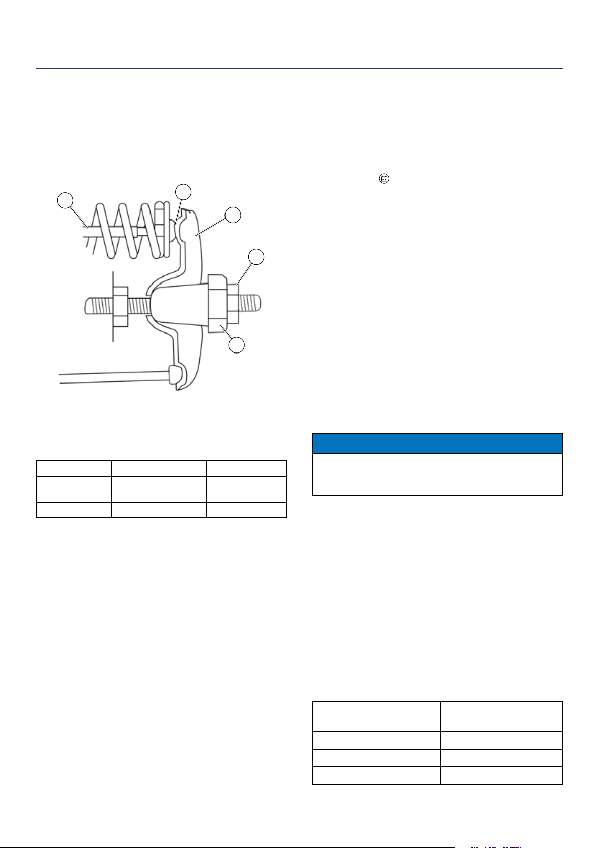
5. Insert a feeler gauge between the rocker arm and
the push rod and check for clearance (see Figure 19).
See table below for valve lash specications
Figure 19
(1) Push Rod, (2) Feeler Gauge Area
(3) Rocker Arm, (4) Jam Nut, (5) Adjusting Nut
Standard Valve Lash
Intake Valve Exhaust Valve
Valve Lash
0.0035 ± 0.0043 in
(0.09 ± 0.11 mm)
0.0043 ± 0.0051 in
(0.11 ± 0.13 mm)
Bolt Torque
8-12N.m 8-12N.m
6. If an adjustment is required, hold the adjusting nut
and loosen the jam nut.
7. Turn the adjusting nut to obtain the correct valve
lash. When the valve lash is correct, hold the ad-
justing nut and tighten the jam nut to 106 in-lb (12
N•m).
8. Recheck the valve lash after tightening the jam nut.
9. Perform this procedure for both the intake and
exhaust valves.
10. Install the rocker arm cover, gasket and spark plug.
CLEANING THE INVERTER
It is important to inspect and clean the inverter before
every use.
Clean All Engine Air Inlet and Outlet Ports – Make
sure all engine air inlet and outlet ports are clean of any
dirt and debris to ensure the engine does not run hot.
MAINTENANCE
1
2
3
4
5
BATTERY SERVICE
To ensure the battery remains charged, the generator
should be started every 2 to 3 months and run for a
minimum of 15 minutes or a charger should be plugged
into the generator and the generator should be charged
overnight. Plug the cord from the charger into the
charging port “
” on the generator. Plug the charger
into a 110/120-volt AC outlet.
Battery Replacement
1. Remove the engine service panel (see Figure 11 in
Air Filter Maintenance section)
2. Remove the spark plug wire from spark plug (see
Figure 16 in Spark Plug Maintenance section).
3. Remove battery service panel
(see Figure 1 Hooking Up the Battery section).
4. Loosen the rubber strap holding the battery in
place.
5. Disconnect the black negative (-) battery cable from
the battery rst.
6. Disconnect the red positive (+) battery cable
second and remove the battery.
NOTICE
Dispose of the used battery properly according to
the guidelines established by your local or state
government.
7. Install the new battery into the generator frame.
8. Connect the red positive (+) battery cable to the
battery rst.
9. Connect the black negative (-) battery cable to the
battery second.
10. Replace rubber strap to hold battery in place.
11. Replace battery service panel.
12. Install the spark plug wire onto spark plug.
13. Replace engine service panel.
See below for the battery specication
when replacing the battery.
After Market Battery
Model
YT5AL
Volts 12
Amp Hr 5
Dimensions 4.63 in by 2.38 in by 5 in
Loading ...
Loading ...
Loading ...