Loading ...
Loading ...
Loading ...
SECTION3: TRACTORSET-UP
IMPORTANT:Your tractor is shipped with motor oil in the engine. However, you MUST check the oil level before
starting the engine and operating. Refer to the separate Briggs & Stratton Operator/Owner Manual (or Tecumseh
eng ne s Owner s Manua ) packed w th your tractor. Read nstruct ons carefu y.
NOTE: Reference to right or left hand side of the unit
is observed from the driver's seat, facing forward.
ToolsRequiredForAssembly
(1) 1/2" socket wrench (for steering wheel)
(1) 9/16" wrench or socket wrench (for seat)
(2) 7/16" wrenches or socket wrenches (for battery)
AttachingtheBatteryCables
NOTE: The positive battery terminal is marked Pos.
(+). The negative battery terminal is marked Neg. (-).
• The positive cable (heavy red wire) is secured to
the positive battery terminal (+) with a hex bolt and
hex nut at the factory. Make certain that the rubber
boot covers the terminal to help protect itfrom
corrosion.
• Remove the hex bolt and wing nut from the
negative cable.
• Remove the black plastic cover, if present, from the
negative battery terminal and attach the negative
cable (heavy black wire) to the negative battery
terminal (-) with the bolt and wing nut.
• Make certain the hold-down rod is in position over
the battery, securing it in place. See Figure 1.
Rubber
Boot
Hex Bolt
Figure 1
NOTE: If the battery is put into service after the date
shown on top of battery, charge the battery as
instructed on page 21 of this manual prior to operating
the tractor.
AttachingTheSteeringWheel
The hardware for attaching the steering wheel has
been packed within the steering wheel, beneath
steering wheel cap. Carefully pry off the steering
wheel cap and remove the hardware.
NOTE: There are two different styles of steering
wheel cap. See Figure 2. Styles vary by model
• Remove the steering bellow from its packaged
location on the PTO (blade engage) lever (found on
the right hand side of tractor). NOTE: Tractor model
698 does NOT require a steering beflow and does
NOT come equipped with one.
• On models so equipped, place the steering bellow
over the steering shaft extending through the dash.
See Figure 2.
NOTE: If the openings on each end of the steering
bellow are two different sizes, the smaller end goes
down, against the dash of the lawn tractor.
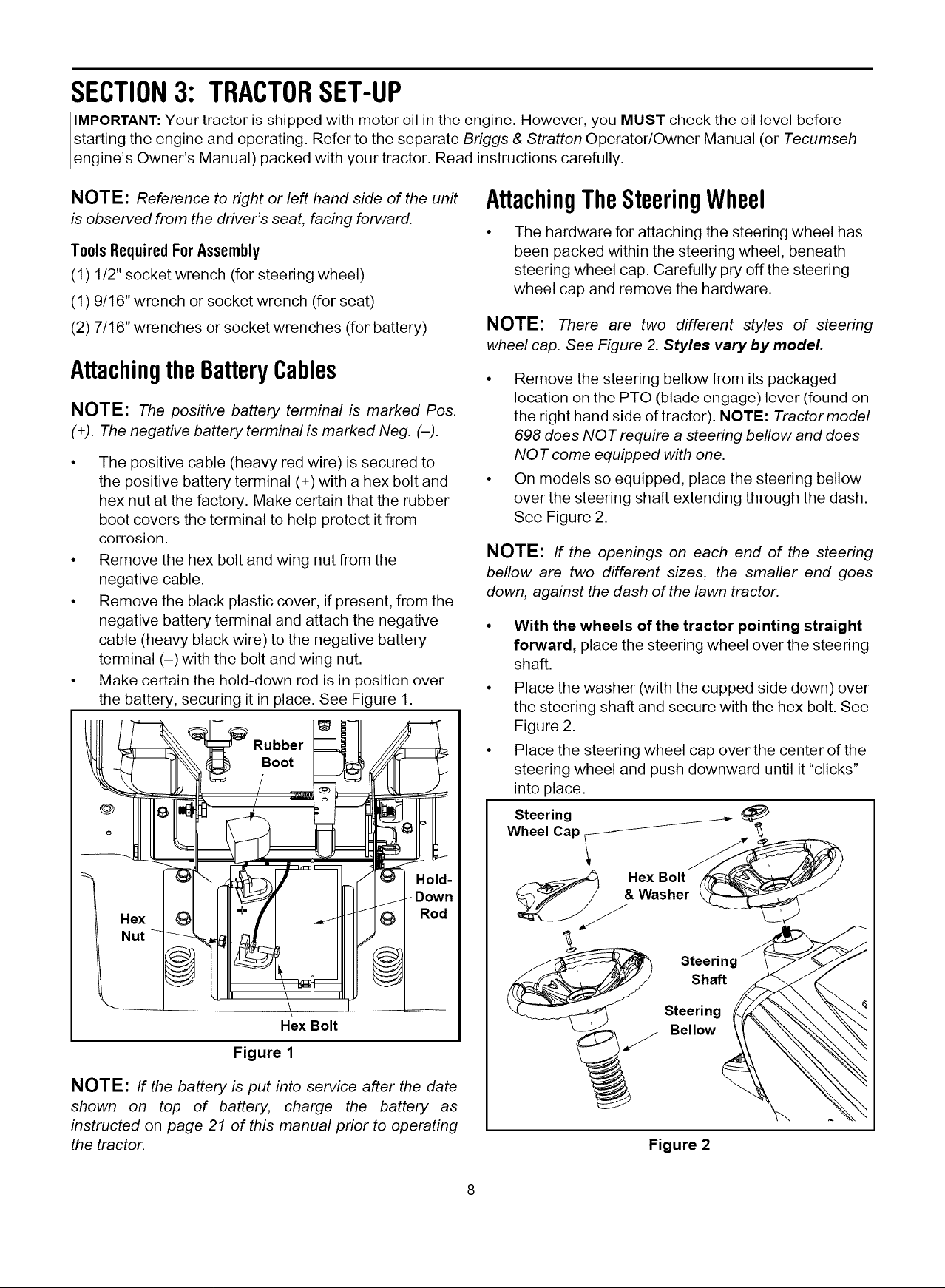
With the wheels of the tractor pointing straight
forward, place the steering wheel over the steering
shaft.
Place the washer (with the cupped side down) over
the steering shaft and secure with the hex bolt. See
Figure 2.
Place the steering wheel cap over the center of the
steering wheel and push downward until it "clicks"
into place.
Steering _
Wheel Cap 1
Washer
Steering
Shaft
Steeri ng
Bellow
Figure 2
Loading ...
Loading ...
Loading ...