Loading ...
Loading ...
Loading ...
NOTE: When reassembfing, make certain belt keeper
pins are assembled in the same locations from which
they were removed.
• Remove the deck belt from around the engine
pulley.Return the PTO (blade engage) lever to the
engaged (all the way forward) position.
• Locate the deck anti-sway rod and adjustable deck
links found near the front of the cutting deck. See
Figure 25 & Figure 26.
• First remove the hairpin clip which secures the anti-
sway rod to the front portion of the cutting deck,
then remove the hairpin clips which secure the
adjustable deck hangers. Retain the hairpin clips.
• Carefully lower the front portion of the deck to the
ground.
• Remove the hairpin clips which secure the rear
deck hangers to the deck stabilizer bracket. See
Figure 27. Retain the hairpin clips.
NOTE: The style and shape the stablizer bracket and
stablizer rod vary. Yours may differ slightly from that
shown in Figure 27.
• Carefully lower the rear portion of the deck to the
ground.
NOTE: For normal service and maintenance, the
deck stabilizer bracket doesn't need to be removed
from the tractor. If removing the cutting deck in order to
mount an attachment, however, remove the stabilizer
bracket by simply removing the hairpin clip which
secures it to the the stabilizer rod. See Figure 27.
• Place the PTO (blade engage) lever in the BLADES
STOP position to raise the lift links up, and out of
the way.
• Carefully slide the deck from beneath the right side
of the lawn tractor.
Tires
Recommended operating tire pressure is
approximately 10 p.s.i. Maximum tire pressure under
any circumstances is 30 p.s.i. Equal tire pressure
should be maintained on all tires.
,_ WARNING: Excessive pressure (over 30
p.s.i.) when seating beads may cause tire/rim
assembly to burst with force sufficient to
cause serious injury.
CuttingBlades
WARNING:
,_ WARNING: Periodically inspect the bladeadapter and/or spindle for cracks or damage,
especially if you strike a foreign object.
Replace immediately if damaged.
O
Rear Deck Hangers
Stabilizer Bracket
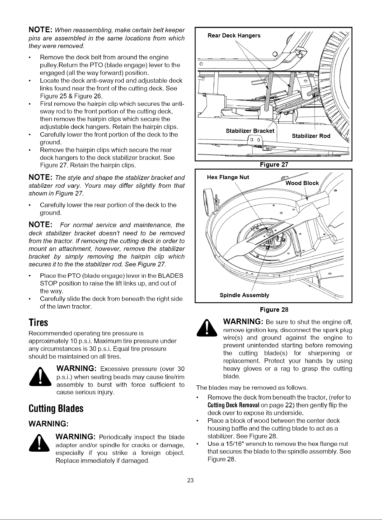
Hex Flange Nut
Figure 27
Spindle Assembly
Figure 28
WARNING: Be sure to shut the engine off,
remove ignition key, disconnect the spark plug
wire(s) and ground against the engine to
prevent unintended starting before removing
the cutting blade(s) for sharpening or
replacement. Protect your hands by using
heavy gloves or a rag to grasp the cutting
blade.
The blades may be removed as follows.
• Remove the deck from beneath the tractor, (refer to
CuttingDeckRemovalon page 22) then gently flip the
deck over to expose its underside.
• Place a block of wood between the center deck
housing baffle and the cutting blade to act as a
stabilizer. See Figure 28.
• Use a 15/16" wrench to remove the hex flange nut
that secures the blade to the spindle assembly. See
Figure 28.
23
Loading ...
Loading ...
Loading ...