Loading ...
Loading ...
Loading ...
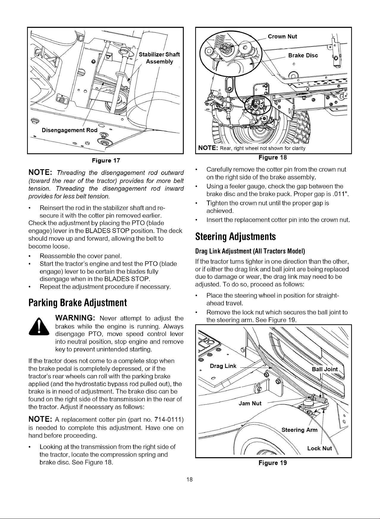
Stabilizer Shaft
Assembly
Disengagement Rod
Figure 17
NOTE: Threading the disengagement rod outward
(toward the rear of the tractor) provides for more belt
tension. Threading the disengagement rod inward
provides for less belt tension.
• Reinsert the rod in the stabilizer shaft and re-
secure it with the cotter pin removed earlier.
Check the adjustment by placing the PTO (blade
engage) lever in the BLADES STOP position. The deck
should move up and forward, allowing the belt to
become loose.
• Reassemble the cover panel.
• Start the tractor's engine and test the PTO (blade
engage) lever to be certain the blades fully
disengage when in the BLADES STOP.
• Repeat the adjustment procedure if necessary.
ParkingBrakeAdjustment
WARNING: Never attempt to adjust the
brakes while the engine is running. Always
disengage PTO, move speed control lever
into neutral position, stop engine and remove
key to prevent unintended starting.
If the tractor does not come to a complete stop when
the brake pedal is completely depressed, or if the
tractor's rear wheels can roll with the parking brake
applied (and the hydrostatic bypass rod pulled out), the
brake is in need of adjustment. The brake disc can be
found on the right side of the transmission in the rear of
the tractor. Adjust if necessary as follows:
NOTE: A replacement cotter pin (part no. 714-0111)
is needed to complete this adjustment. Have one on
hand before proceeding.
• Looking at the transmission from the right side of
the tractor, locate the compression spring and
brake disc. See Figure 18.
Crown Nut
NOTE: Rear, right wheel not shown for clarity
Figure 18
• Carefully remove the cotter pin from the crown nut
on the right side of the brake assembly.
• Using a feeler gauge, check the gap between the
brake disc and the brake puck. Proper gap is .011"
• Tighten the crown nut until the proper gap is
achieved.
• Insert the replacement cotter pin into the crown nut.
SteeringAdjustments
BragLink Adjustment(AllTractors Model)
If the tractor turns tighter in one direction than the other,
or if either the drag link and ball joint are being replaced
due to damage or wear, the drag link may need to be
adjusted. To do so, proceed as follows:
• Place the steering wheel in position for straight-
ahead travel.
• Remove the lock nut which secures the ball joint to
the steering arm. See Figure 19.
Drag Link
Steering Arm
Figure 19
Lock Nut
18
Loading ...
Loading ...
Loading ...