Loading ...
Loading ...
Loading ...

16 - English
LATCH
ASSEMBLY
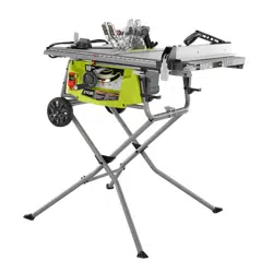
UNFOLDING THE STAND SUPPORTS
See Figure 7.
NOTE: Do not use this leg stand with other equipment or
for other purposes.
NOTE: During shipping, the foam block between the saw’s
housing and motor holds the stand leg bolts in place.
Remove the foam block before assembling the stand, making
sure the bolts remain in place.
Place the saw on a flat surface with the underside of the
saw facing up.
Cut the zip tie that holds the support brackets together.
Fold out the stand. Use the latch to secure the free end
of the support bracket to the frame of the saw.
INSTALLING STAND LEGS
See Figure 8 - 9.
Many of the leg stand parts are movable. All hardware must
be tightened securely but not so tight that the leg stand won’t
open and close. For easier assembly, match letter to letter,
then install hardware.
Locate the following parts:
Stand leg .....................................................................4
Lock Nut (M8) ............................................................. 2
Assemble each side separately. Install all legs with feet
pointing outward.
Carefully remove the bolt from the support bracket while
holding the pivot plate in place. Set the bolt aside.
Locate one of the legs with two holes drilled into it. Insert
the leg into the inner stand support bracket tube.
NOTE: The two holes are for installing the crosspiece.
Align the hardware holes of the inner and outer support
brackets and pivot plate. Insert the bolt through all pieces
and secure with a lock nut. Tighten the nut using a
13 mm wrench. Then loosen nut slightly to allow legs to
pivot freely.
HOLES
PIVOT
PLATE
OUTER STAND
SUPPORT
BRACKET
INNER STAND
SUPPORT
BRACKET
LOCK
NUT
BOLT
Fig. 9
Fig. 7
LEG
NOTE: Do not overtighten as this will not allow the stand
to move freely.
To repeat on the other side, remove the bolt. Insert the
leg with two holes into the inner stand support bracket.
Insert the adjustment foot into the outer support bracket.
LETTERS
Fig. 8
Loading ...
Loading ...
Loading ...