Loading ...
Loading ...
Loading ...

12 - English
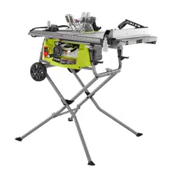
FEATURES
HEIGHT/BEVEL ADJUSTING HANDWHEEL - Located on
the front of the saw, use this handwheel to lower and raise
the blade for height adjustments or blade replacement. This
handwheel also makes the adjustment for bevel angles easy.
MITER GAUGE - The miter gauge aligns the wood for a
cross cut. The easy-to-read indicator shows the exact angle
for a miter cut.
MITER GAUGE GROOVE - The miter gauge rides in the
groove on the saw table.
OUTFEED SUPPORT - This table extension at the back of
the tool gives the operator additional support when cutting
long workpieces.
RIP FENCE - A sturdy metal fence guides the workpiece
and is secured with the locking handle. Push stick storage
is located on the rip fence.
NOTE: Do not place the rip fence on the left side of the blade
when cutting material greater than 3/4 inches thick.
RIP SCALE - Located on the front rail, the easy-to-read rip
scale provides precise measurements for rip cuts.
RIVING KNIFE - A removable metal piece of the blade
guard assembly, slightly thinner than the saw blade, which
helps keep the kerf open and prevent kickback. When in the
through sawing, or “up” position, it is higher than the saw
blade. When in the non-through sawing, or “down” position,
it is below the saw blade teeth.
SLIDING TABLE EXTENSION - Located on the right side
of the saw table, this table extension gives the operator ad-
ditional support when cutting wide workpieces.
SWITCH ASSEMBLY - This saw has an easy access switch
assembly located below the front rail. To lock the switch, in-
stall a padlock (not included) through the holes in the switch
and cover. Make certain the switch is inoperable. If the switch
is still operable with the padlock installed, a padlock with
a larger shackle diameter must be used. Store the padlock
key in another location.
OPERATING COMPONENTS
The upper portion of the blade projects up through the table
and is surrounded by an insert called the throat plate. The
height of the blade is set with a handwheel on the front of
the saw. Detailed instructions are provided in the Operation
section of this manual for the basic cuts: cross cuts, miter
cuts, bevel cuts, and compound cuts.
The rip fence is used to position work for lengthwise cuts.
A scale on the front rail shows the distance between the rip
fence and the blade.
It is very important to use the blade guard assembly for all
through-sawing operations. The blade guard assembly in-
cludes: riving knife and blade guard with anti-kickback pawls.
SWITCH ASSEMBLY
See Figure 4.
This saw is equipped with an on/off switch that has a built-in
locking feature. This feature is intended to prevent unauthor-
ized and possible hazardous use by children and others.
NOTE: The switch cover does not have to be raised to oper-
ate the switch.
TO TURN THE SAW ON:
Press the top button on the switch to turn the saw on.
NOTE: If AC power is disconnected or interrupted while
the saw is running, the saw will turn off. To restart the
saw, restore AC power and press the top of the switch.
TO TURN THE SAW OFF:
Press the bottom button on the switch to turn the saw
off.
TO LOCK THE SAW:
With the saw turned off, install a padlock (not included)
through the holes in the switch and switch cover.
WARNING:
ALWAYS make sure your workpiece is not in contact with
the blade before operating the switch to start the tool.
Failure to heed this warning may cause the workpiece to
be kicked back toward the operator and result in serious
personal injury.
WARNING:
To reduce the risk of accidental starting, always make
sure the top button on the switch is not depressed before
plugging tool into the power source.
Fig. 4
SWITCH IN
LOCKED POSITION
SWITCH ON SWITCH OFF
Loading ...
Loading ...
Loading ...