
ENGLISH ESPAÑOL
LG
Window-Type Air Conditioner
OWNER'S MANUAL
LG
MODELS: LB8000ER,LW8000ER
PRECAUTIONS
www.lgservice.com
IMPORTANT
• Please read this owner's manual carefully and thoroughly
before installing and operating your room air conditioner.
• Please retain this owner's manual for future reference after
reading it thoroughly.
• Antes de instalar y poner en marcha su ventilador de
casa, haga el favor de leer cuidadosamente esta
instrucción de Usuario.
• Luego de su lectura, guarde este manual para el futuro
usuario para las referencias.
Downloaded from www.ManualsFile.com manuals search engine
2
Window-Type Air Conditioner Owner’s Manual
TABLE OF CONTENTS
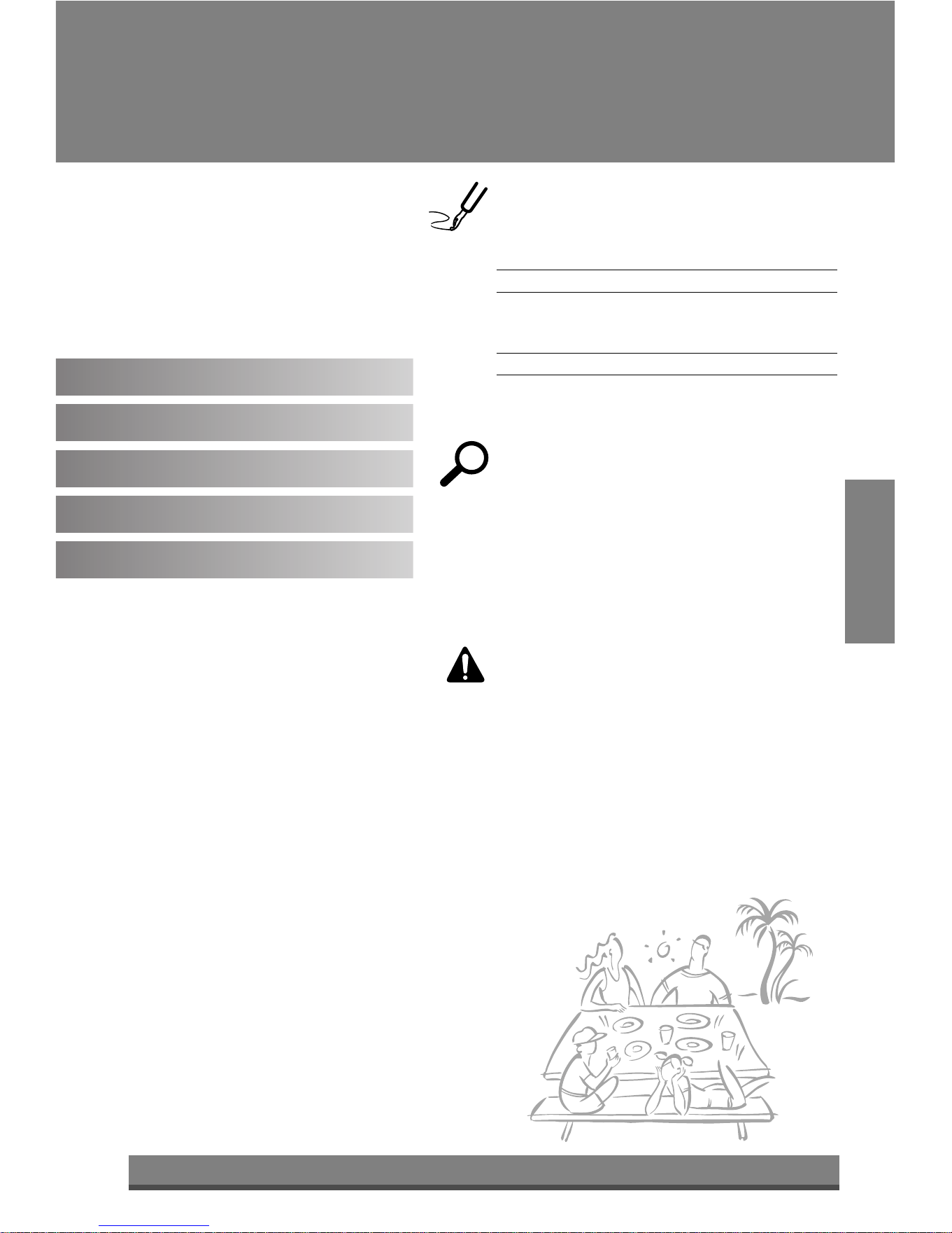
1. Safety Precautions
2. Operating Instructions
3. Care and Maintenance
4. Hardware Installation
5. Common Issues
FOR YOUR RECORDS
Write the model and serial numbers here:
Model #
Serial #
You can find them on a label on the side of each unit.
Dealer's Name
Date Purchased
■ Staple your receipt to this page in the event you need
it to prove date of purchase or for warranty issues.
READ THIS MANUAL
Inside you will find many helpful hints on how to use
and maintain your air conditioner properly. Just a little
preventive care on your part can save you a great deal
of time and money over the life of your air conditioner.
You'll find many answers to common problems in the
chart of troubleshooting tips. If you review our chart of
Troubleshooting Tips first, you may not need to call
for service at all.
PRECAUTION
• Contact the authorized service technician for repair or
maintenance of this unit.
• Contact the installer for installation of this unit.
• The air conditioner is not intended for use by young
children or invalids without supervision.
• Young children should be supervised to ensure that
they do not play with the air conditioner.
• When the power cord is to be replaced, replacement
work shall be performed by authorized personnel only
using only genuine replacement parts.
• Installation work must be performed in accordance with
the National Electric Code by qualified and authorized
personnel only.
Downloaded from www.ManualsFile.com manuals search engine
3
ENGLISH
Precautions
Safety
Precautions
To prevent injury to the user or other people and property damage, the following instructions must
be followed.
■ Incorrect operation due to ignoring instruction will cause harm or damage. The seriousness is
classified by the following indications.
WARNING
CAUTION
This symbol indicates the possibility of death or serious injury.
This symbol indicates the possibility of injury or damage to properties only.
■ Meanings of symbols used in this manual are as shown below.
Be sure not to do.
Be sure to follow the instruction.
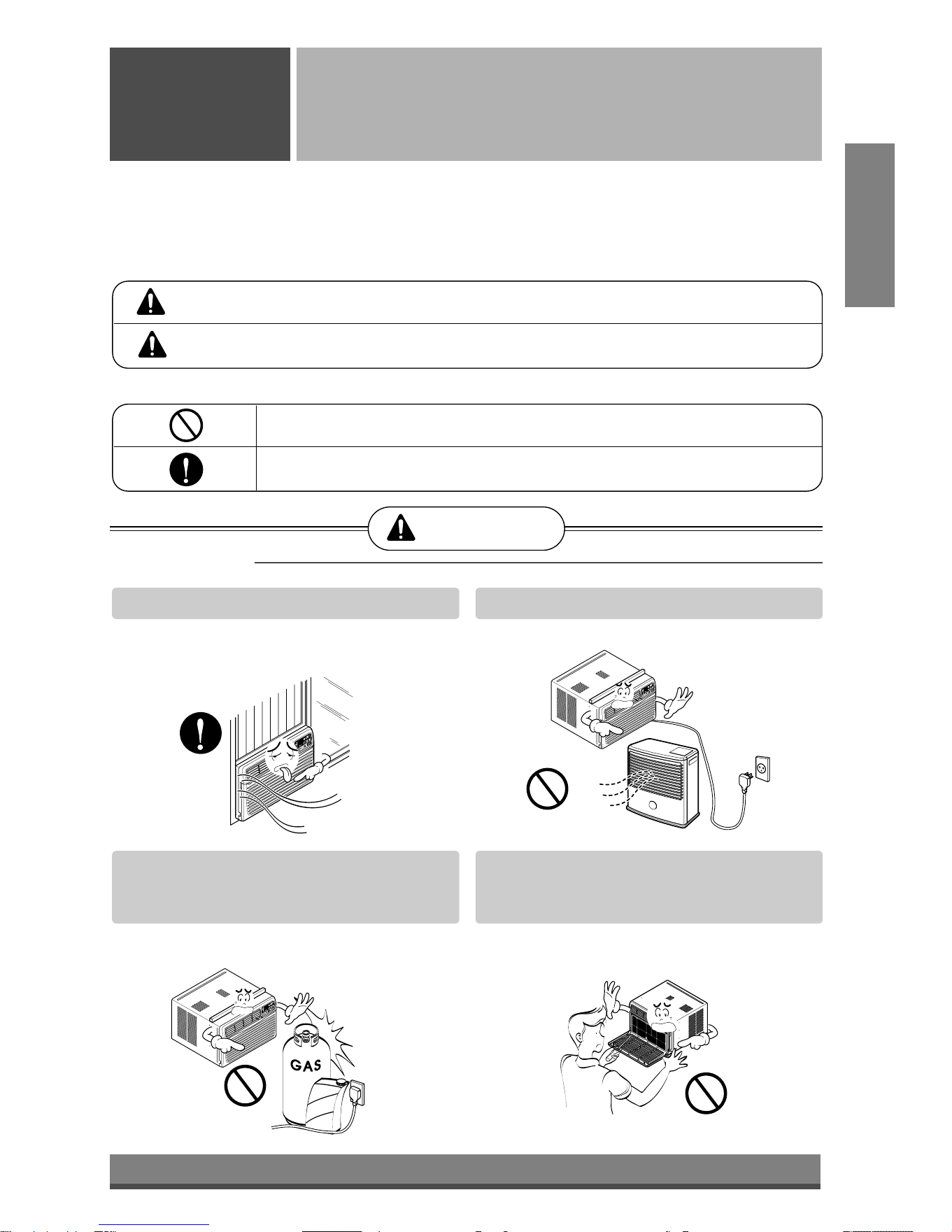
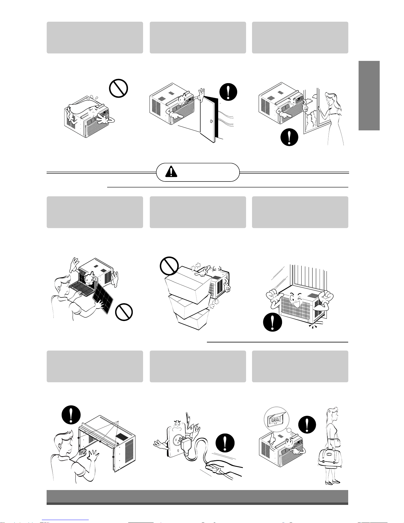
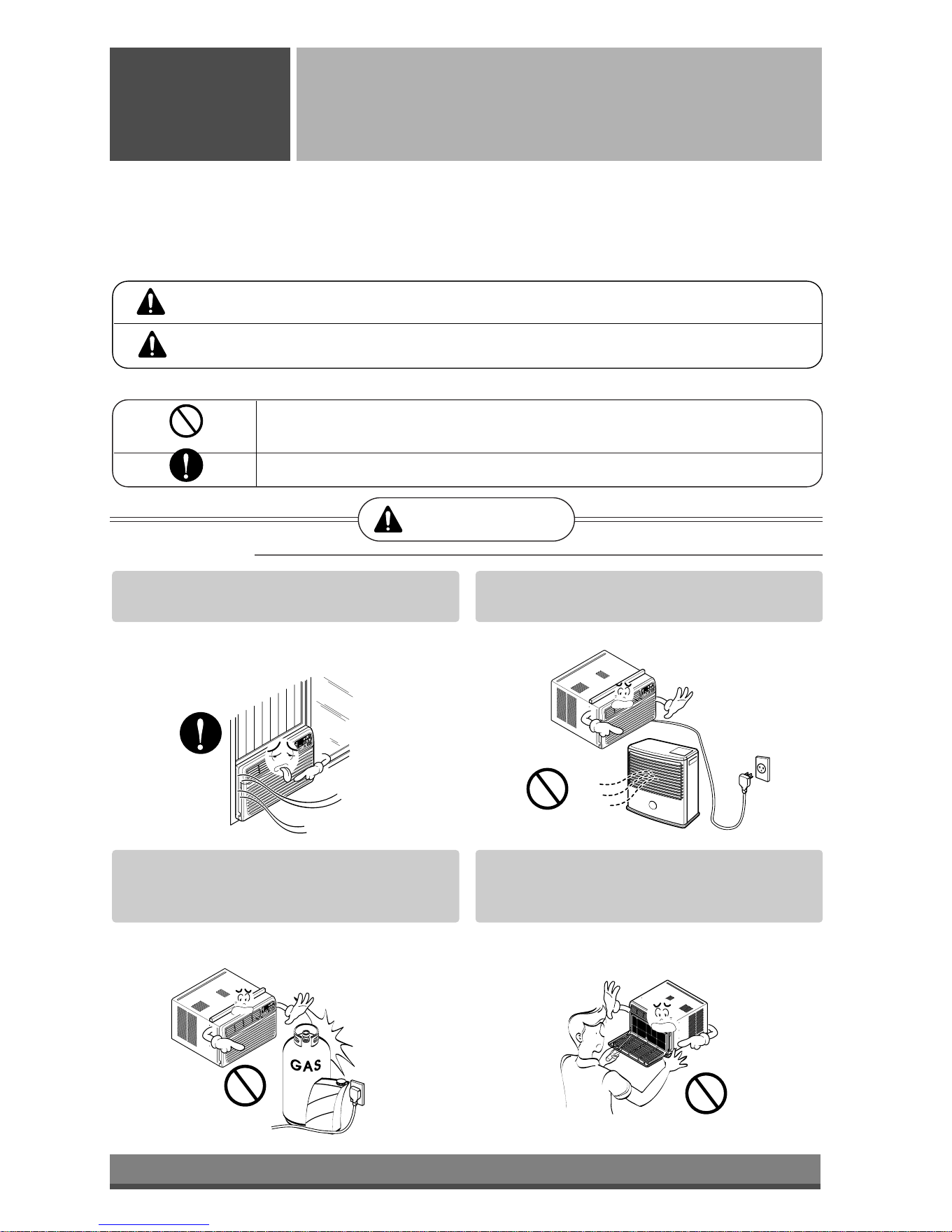
WARNING
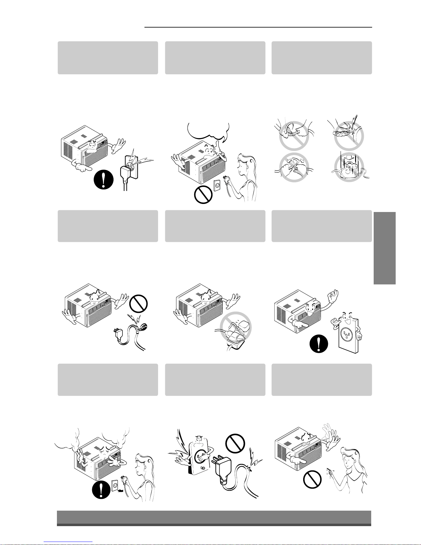
■ Installation
Always install the expansion panel(s).
• No installation may cause fire and electric
shock accident.
Do not place the power cord near a heater.
• It may cause fire and electric shock.
Do not use the power cord near flammable
gas or combustibles such as gasoline,
benzene, thinner, etc.
• It may cause explosion or fire.
Do not disassemble or modify products.
• It may cause failure and electric shock.
Gasoli
n
Downloaded from www.ManualsFile.com manuals search engine
4
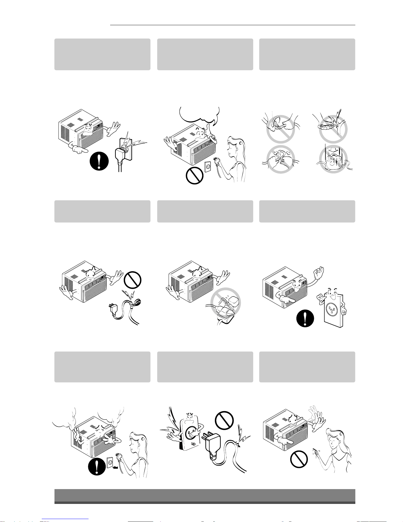
■ Operation
Plug in the power plug
properly.
• Otherwise, it will cause
electric shock or fire due to
heat generation or electric
shock.
Do not operate or stop the
unit by inserting or pulling
out the power plug.
• It will cause electric shock or
fire due to heat generation.
Do not damage or use an
unspecified power cord.
• It will cause electric shock or
fire.
Do not modify power cord
length.
• It will cause electric shock or
fire due to heat generation.
Do not share the outlet with
other appliances.
• It will cause electric shock or
fire due to heat generation.
Always plug into a
grounded outlet.
• No grounding may cause
electric shock (See
Installation Manual).
Unplug the unit if strange
sounds, odors, or smoke
come from it.
• Otherwise it may cause fire
and electric shock accident.
Do not use the socket if it is
loose or damaged.
• It may cause fire and electric
shock.
Do not operate with wet
hands or in damp
environment.
• It will cause electric shock.
ON
ON
Downloaded from www.ManualsFile.com manuals search engine
5
ENGLISH
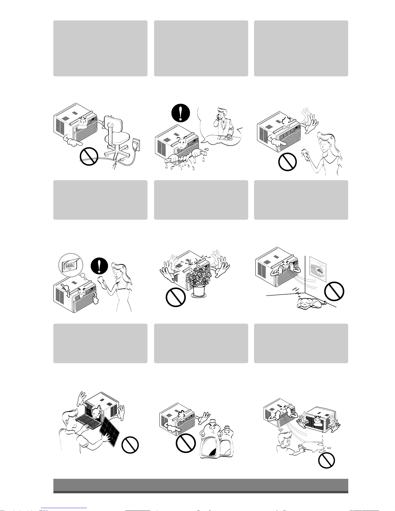
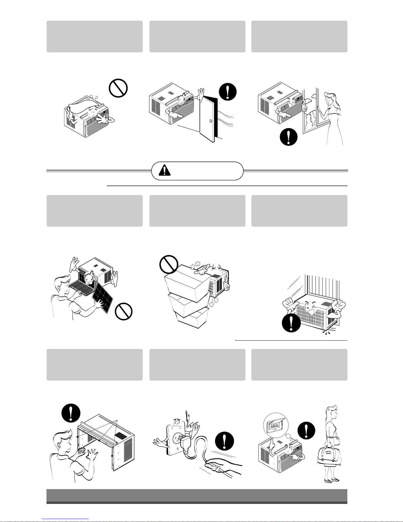
Do not allow water to run
into electric parts.
• It will cause failure of machine
or electric shock.
Leave the door closed while
the air conditioner is
running.
• It is not designed to cool the
entire house.
Ventilate before operating
air conditioner when gas
goes out.
• It may cause explosion, fire,
and burn.
Never touch the metal parts
of the unit when removing
the filter.
• They are sharp and may
cause injury.
Do not block the inlet or
outlet.
• It may cause failure of
appliance or accident.
Ensure that the outer case
is not damaged by age or
wear.
• If leaving appliance damaged,
there is concern of damage
due to the falling of product.
Be cautious not to touch the
sharp edges when
installing.
• It may cause injury.
Hold the plug by the head
when taking it out.
• It may cause electric shock
and damage.
Turn off the main power
switch when not using it for
a long time.
• Prevent accidental startup
and the possibility of injury.
CAUTION
■ Installation
Sharp
edges
■ Operation
Downloaded from www.ManualsFile.com manuals search engine
6
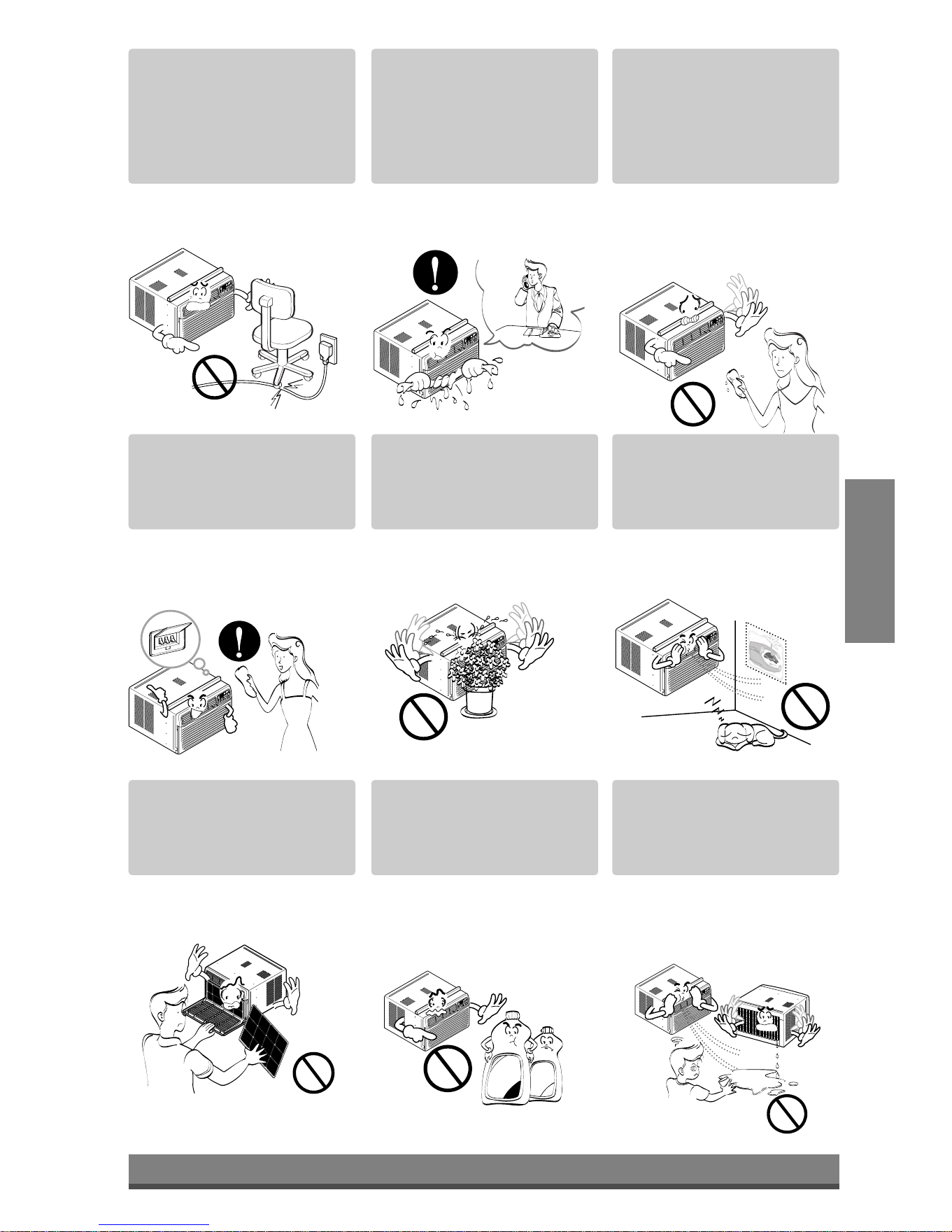
Do not place heavy object
on the power cord and take
care so that the cord should
not be pressed.
• There is danger of fire or
electric shock.
If water enters the product,
turn off the the power switch
of the main body of appliance.
Contact service center after
taking the power-plug out
from the socket.
Do not clean the air
conditioner with water.
• Water may enter the unit and
degrade the insulation. It may
cause an electric shock.
Turn off the power and
breaker firstly when
cleansing the unit.
• Since the fan rotates at high
speed during operation, it
may cause injury.
Do not put a pet or house
plant where it will be
exposed to direct air flow.
• This could injure the pet or
plant.
Do not use this appliance
for special purposes such
as pets, foods, precision
machinery, or objects of art.
• It is an air conditioner, not a
precision refrigeration system.
Always insert the filter
securely.
Clean it every two weeks.
• Operation without filters will
cause failure.
Use a soft cloth to clean. Do
not use wax, thinner, or a
strong detergent.
• The appearance of the air
conditioner may deteriorate,
change color, or develop
surface flaws.
Do not drink water drained
from air conditioner. / Do
not direct airflow at room
occupants only.
• It contains containments and
will make you sick. / This
could damage your health.
• It will cause electric shock
or failure of machine.
W
a
x
Thinner
Downloaded from www.ManualsFile.com manuals search engine

TITLE 1
SECTION
7
ENGLISH
Prior to Operation
Safety
Precautions
Preparing for operation
Contact an installation specialist for installation.
Plug in the power plug properly.
Do not share the same outlet with other appliances
Do not use an extension cord.
Do not start/stop operation by plugging/unplugging the power cord.
If cord/plug is damaged, replace only with an authorized part.
6
5
4
3
2
1
Usage
Cleaning and maintenance
Do not use water to clean inside the air conditioner. Exposure to water can destroy the insulation, leading
to possible electric shock.
When cleaning the unit, first make sure that the power and breaker are turned off. The fan rotates at a
very high speed during operation. There is a possibility of injury if the unit’s power is accidentally
triggered on while cleaning inner parts of the unit.
2
1
Service
For repair and maintenance, contact your authorized service dealer.
Being exposed to direct airflow for an extended period of time could be hazardous to your health. Do not
expose occupants, pets, or plants to direct airflow for extended periods of time.
Due to the possibility of oxygen deficiency, ventilate the room when using together with stoves or other
heating devices.
Do not use this air conditioner for non-specified special purposes (e.g. preserving precision devices,
food, pets, plants, and art objects). Usage in such a manner could harm such property.
3
2
1
Downloaded from www.ManualsFile.com manuals search engine
8
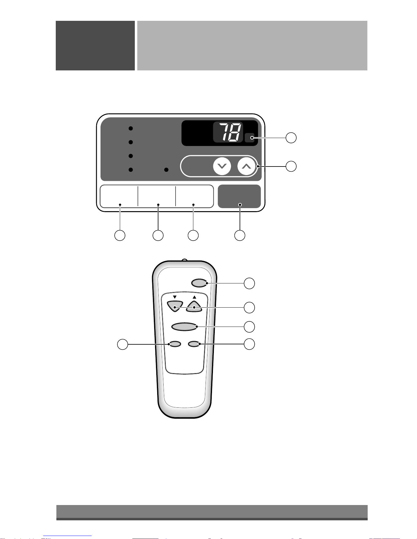
Power
Temp
Fan Speed
Timer Mode
1
2
3
4
5
'
F
TIMER POWERMODE
TEMP
FAN
SPEED
F1 LOW
F2 MED
F3 HIGH
Dry Timer
Fan
Energy
Saver
Cool
1
2
6
3 45
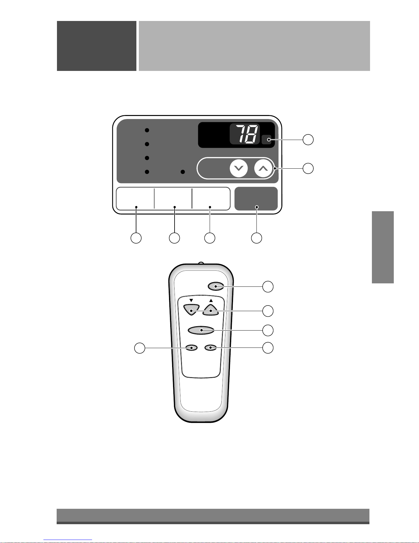
Remote Control Operations
Operating
Instructions
The remote control and control panel will look like those represented in the following pictures.
Downloaded from www.ManualsFile.com manuals search engine
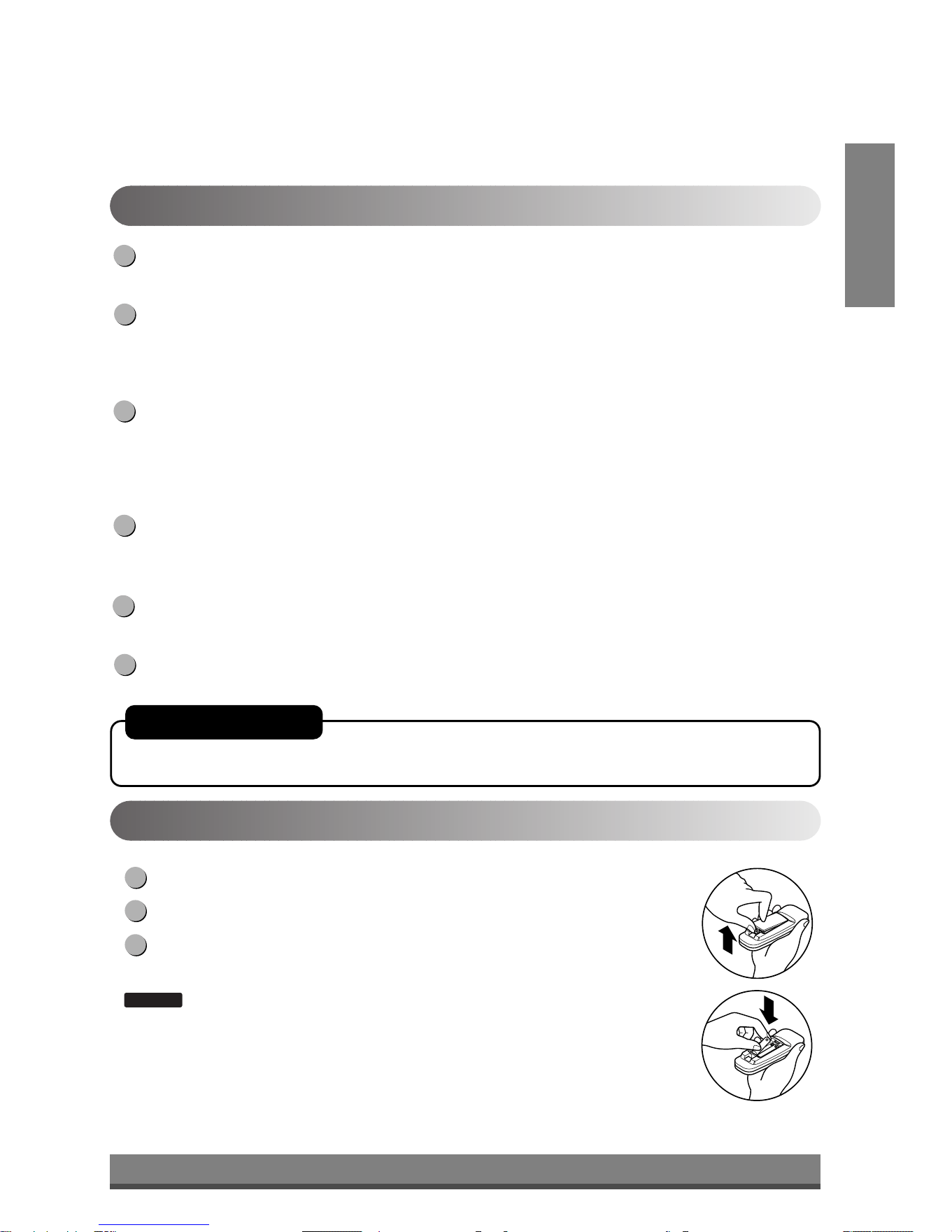
9
ENGLISH
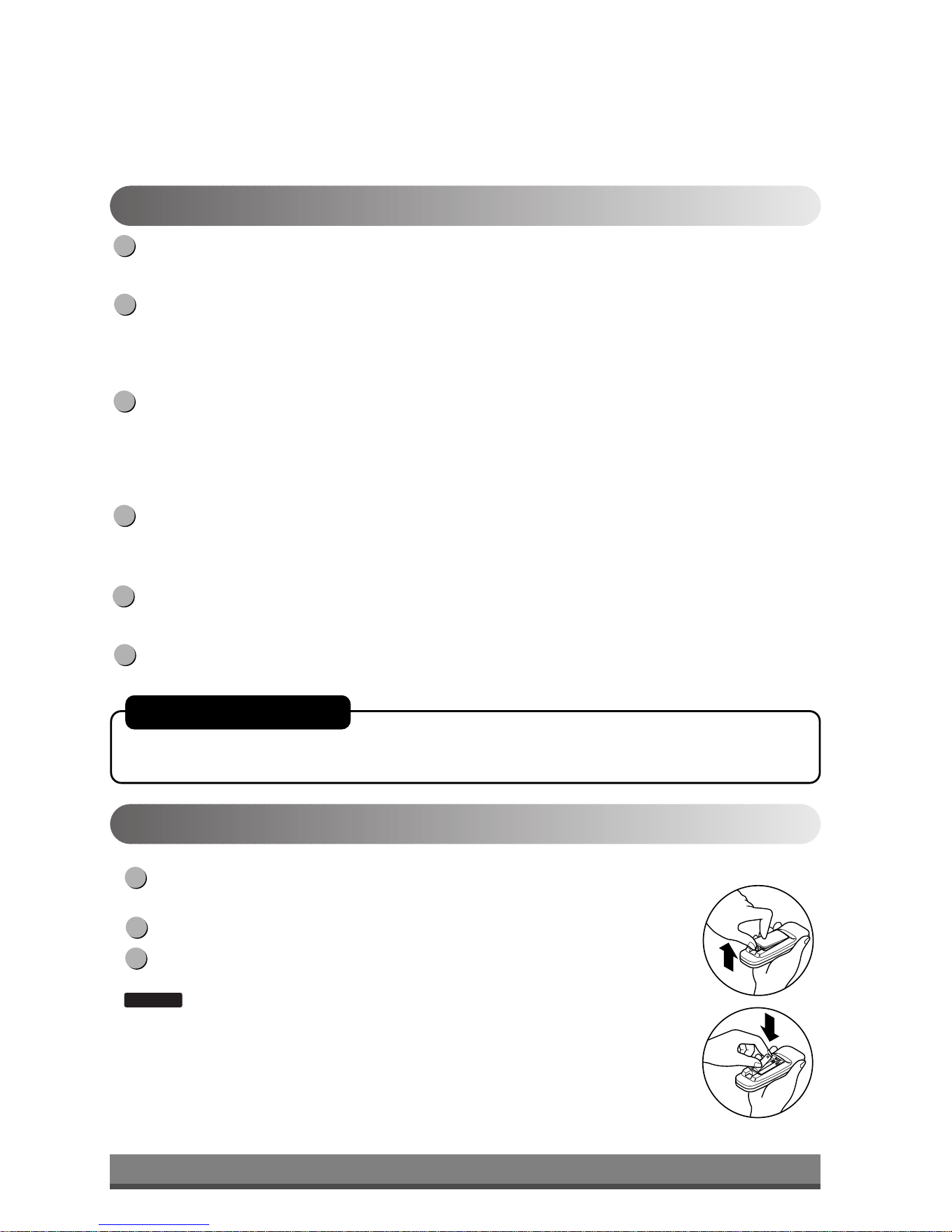
Push out the cover on the back of the remote control with your thumb
Pay attention to polarity and insert two new AAA 1.5V batteries.
Reattach the cover.
:
Do not use rechargeable batteries. Make sure that both batteries are new.
• In order to prevent discharge, remove the batteries from the remote control if the air
conditioner is not going to be used for an extended period of time
Keep the remote control away from extremely hot or humid places.
To maintain optimal operation of the remote control, the remote sensor should not be
exposed to direct sunlight.
• The remote control can be mounted on a wall using the mountable holder.
NOTICE
3
2
1
Inserting the Remote Control Batteries
POWER
Operation starts when this button is pressed and stops when you press the button again.
TEMPERATURE CONTROL
The thermostat monitors room temperature to maintain the desired temperature.
The thermostat can be set between 60°F~86°F (16°C~30°C).
The unit takes an average of 30 minutes to adjust the room temperature by 1°F.
OPERATION MODE SELECTOR
Select cooling mode to cool the room.
Select energy saver mode for energy saving operation.
Select fan mode for basic ventilating fan operation.
Select dry mode for dry operation.
FAN SPEED SELECTOR
For increased power while cooling, select a higher fan speed.
3 steps: High ➔ Low ➔ Med
ON/OFF TIMER
The timer can be set to start and stop the unit in hourly increments (up to 12 hours).
REMOTE CONTROL SENSOR
6
5
4
3
2
1
Remote Control OperationsRemote Control Operations
AUTO RESTART
In failure of electric power, the unit runs as previous setting operation.
Downloaded from www.ManualsFile.com manuals search engine
10
OPEN
VENTCLOSE
Part A
Adjusting the Air Flow Direction
Operating
Instructions
Vent Control
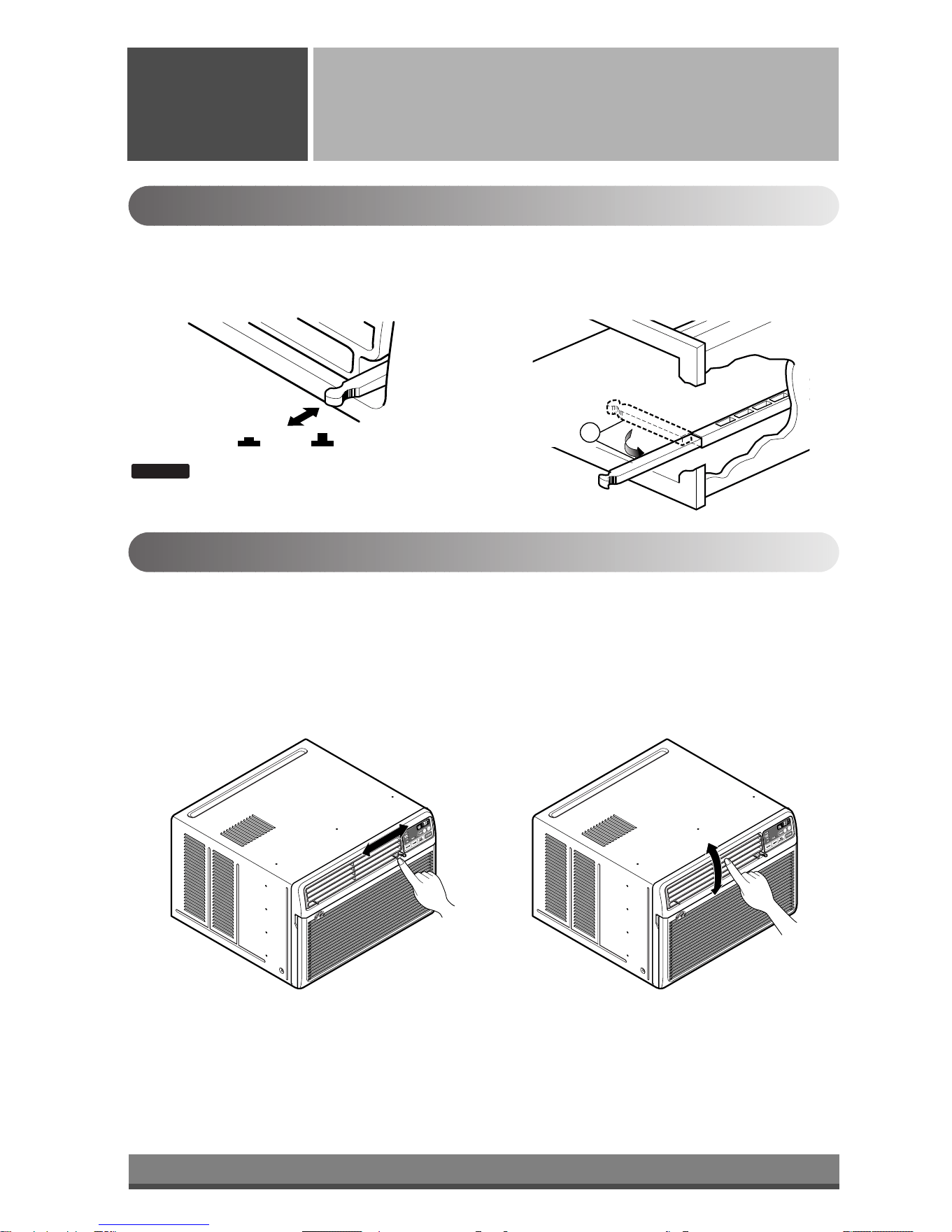
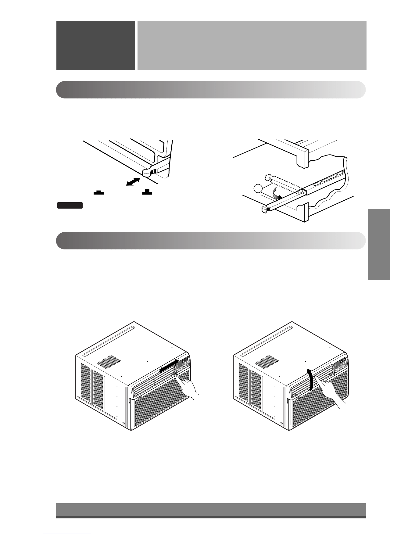
For maximum cooling efficiency, CLOSE the vent. This will allow internal air circulation.
OPEN the vent to discharge stale air.
Adjusting the Air Flow Direction
• Recommended orientation of louvers
Adjust louvers to face upwards when cooling to maximize cooling efficiency.
Airflow can be adjusted by changing the direction of the air conditioner's louvers. This can also increase the
cooling efficiency of the air conditioner.
: Before using the ventilation feature, position
the vent lever straight by pulling Part A out
and snapping it into place.
NOTICE
Adjusting horizontal air flow Adjusting vertical air flow
• Adjusting Horizontal Air Flow Direction
Adjusting the vertical louvers left and right will
change horizontal airflow.
• Adjusting Vertical Air Flow Direction
Adjusting the horizontal vane up and down will
change vertical airflow. The vane can be adjusted
by nudging the vane backward or forward.
Downloaded from www.ManualsFile.com manuals search engine
11
ENGLISH
Drain pipe
Drain cap
Care and Maintenance
Care and
Maintenance
Turn the power off and unplug the power plug before cleaning the air conditioner.
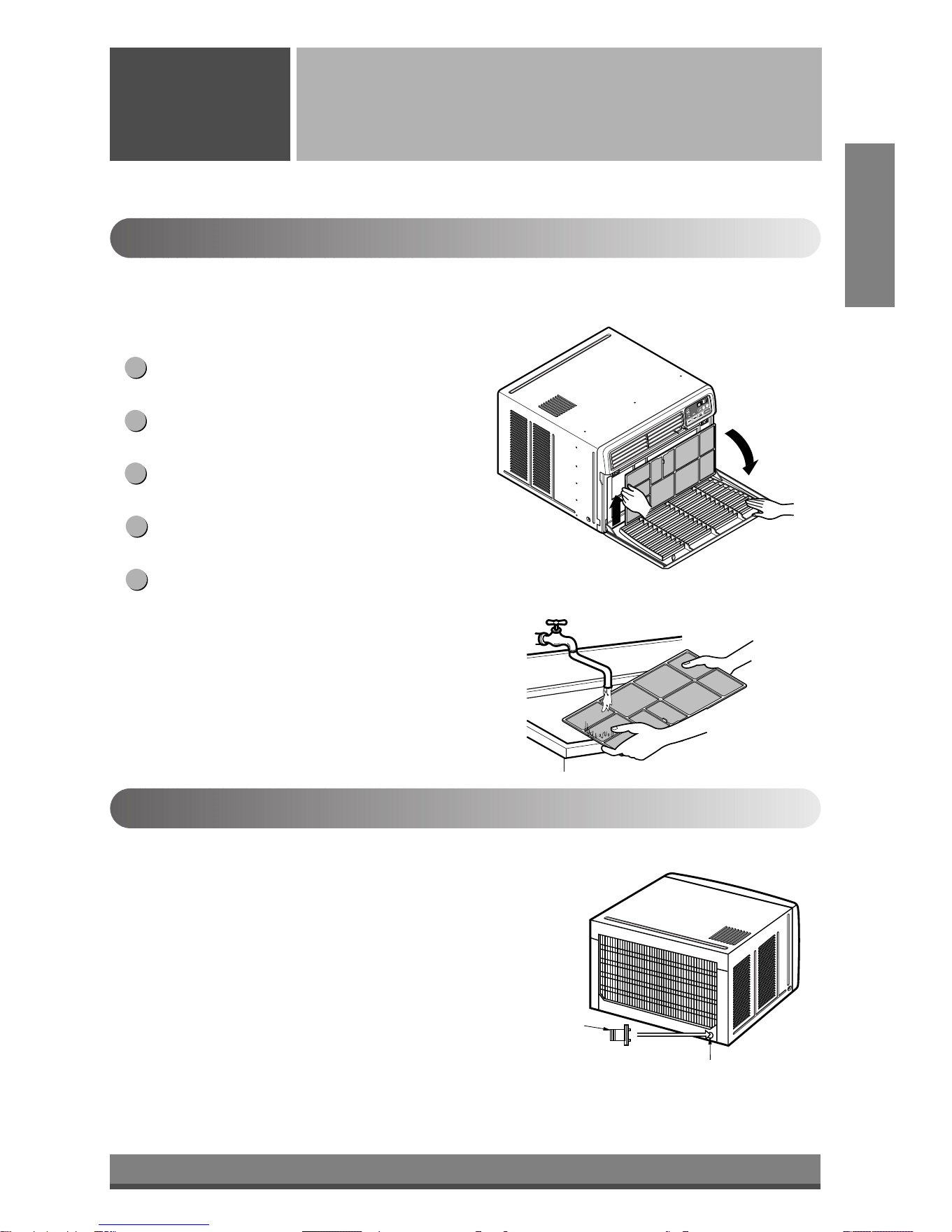
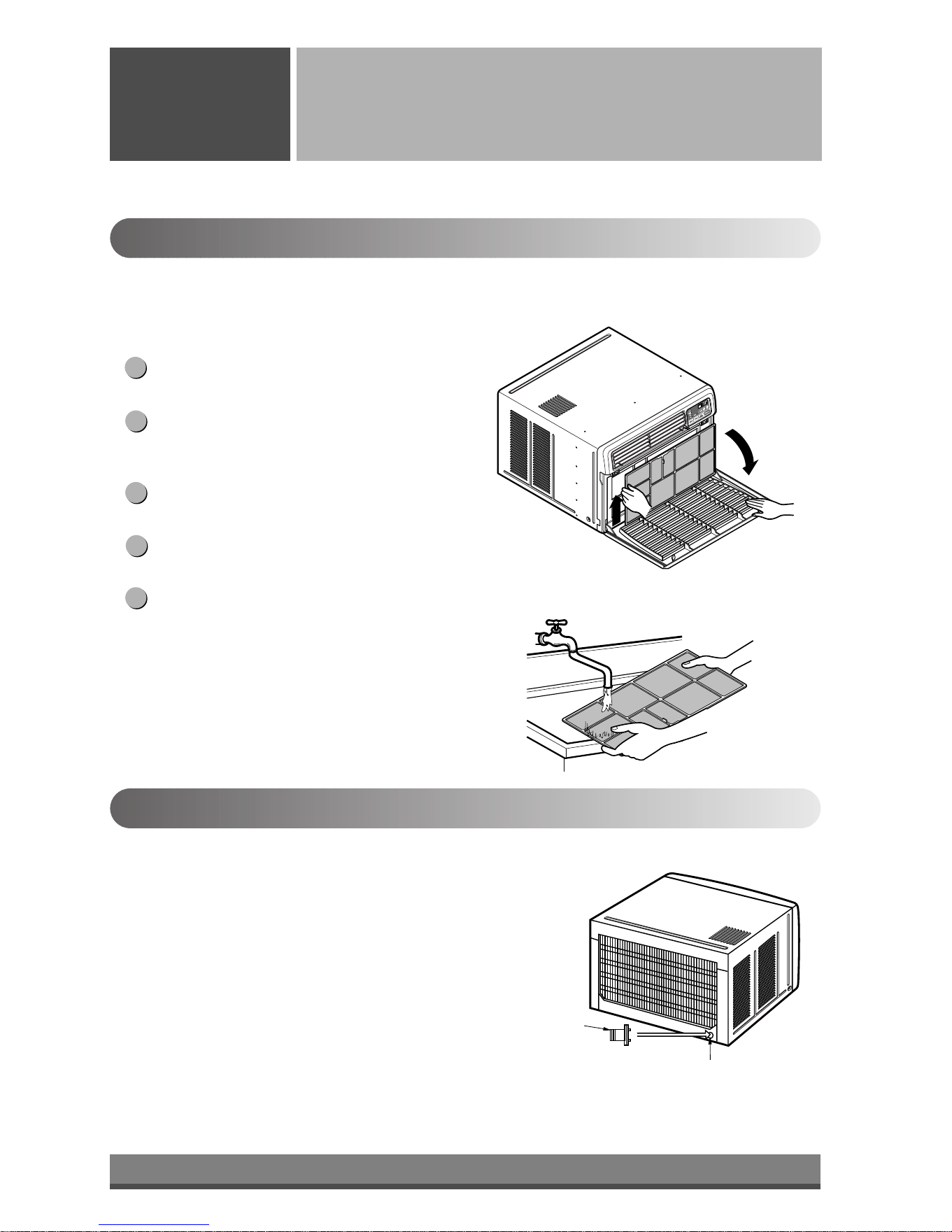
Air Filter
The air filter behind the inlet grille should be checked and cleaned at least once every 2 weeks (or as
necessary) to maintain optimal performance of the air conditioner.
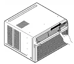
How to remove the air filter
The grille may be opened from the top for easy
maintenance after installation.
Open the inlet grille by pulling off the exposed door
on the top of the unit (based on installation).
Pull the tab slightly to release the filter. Pull the filter
in the same direction as the opening.
Clean the filter with warm, soapy water. The water
should be below 40°C (104°F).
Rinse off and gently shake off excess water from the
filter. Let it dry before replaceing it.
5
4
3
2
1
Drainage
The base pan may overflow due to high humidity. To drain the excess
water, remove the drain cap from the back of the unit and secure the
drainpipe.
When pressing the drainpipe into place, apply force in the direction
away from the fins to avoid injuring yourself.
Downloaded from www.ManualsFile.com manuals search engine
TITLE 1
SECTION
12
4
1
2
3
13
11
14
12
7
10
B
A
6
5
8
15
9
Power Cord
Power Cord
Hardware Installation
Hardware
Installation
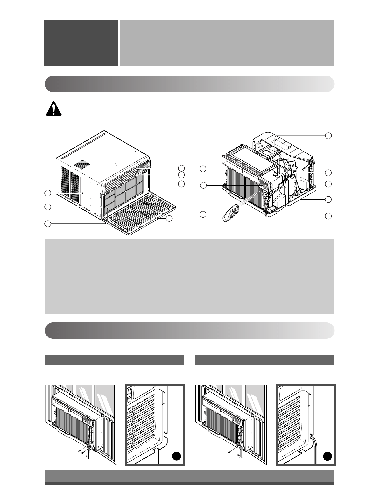
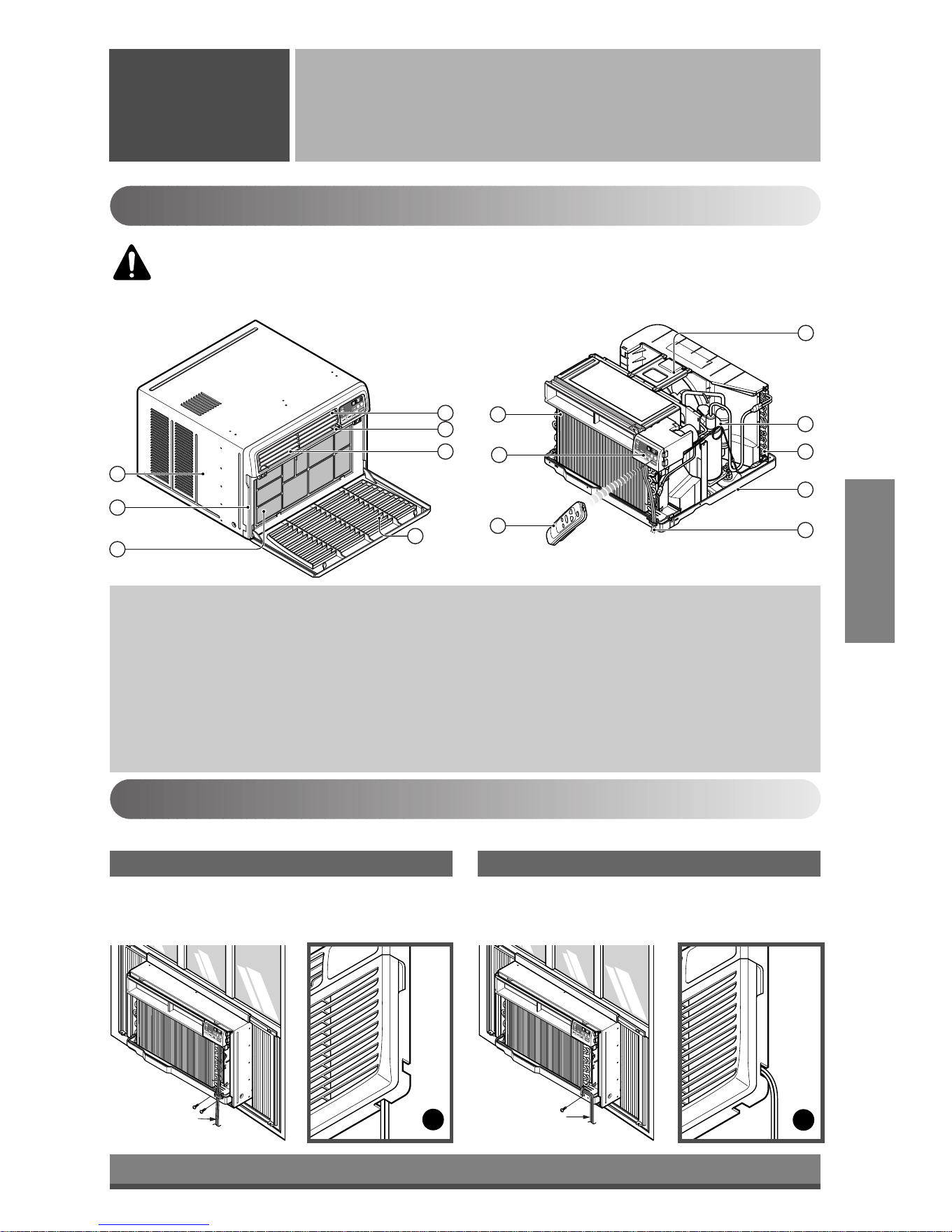
Product Features
1. CABINET
2. FRONT GRILLE
3. AIR FILTER
4. AIR INTAKE (INLET GRILLE)
5. AIR DISCHARGE
6. VERTICAL AIR DEFLECTOR
(HORIZONTAL LOUVER)
7. EVAPORATOR
8. HORIZONTAL AIR DEFLECTOR
(VERTICAL LOUVER)
9. CONTROL PANEL
10. POWER CORD
11. COMPRESSOR
12. BASE PAN
13. BRACE
14. CONDENSER
15. REMOTE CONTROLLER
Installing the Power cord
You can choose between two methods below according to your window stool shape and preference.
• Fasten the stopper using 2 screw holes, and lead
out the power cord through slit "A".
• Fasten the stopper using left screw hole, and rotate
properly to lead the power cord out through slit "B".
Using slit "A" Using slit "B"
CAUTION: This appliance should be installed in accordance with national wiring
regulations. The following information serves acts as a guide to help to explain product
features.
Downloaded from www.ManualsFile.com manuals search engine
13
About
1
/2"
30"~60"
Awning
Cooled air
Fence
Over 20"
Heat
radiation
23" to 36"
15" min.
Inner sill
Offset
Window
Sash
Sill
Exterior
Interior wall
20
1
/12" min.
(Without frame curtain)
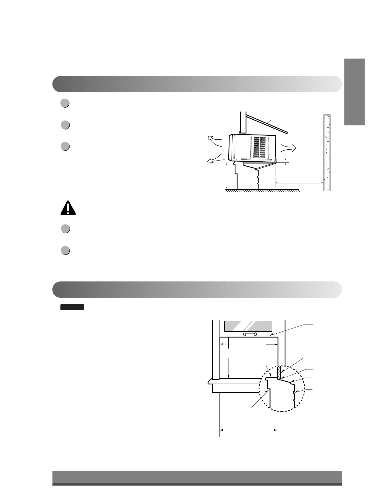
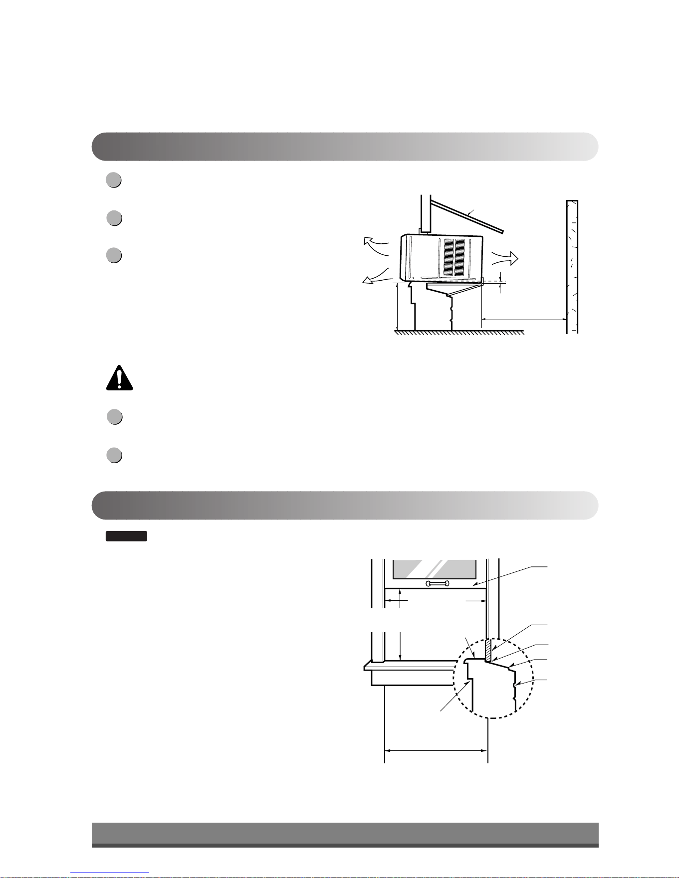
How to Install the Unit
To prevent vibration and noise, make sure the unit
is installed securely and firmly.
Install the unit where the sunlight does not shine
directly on the unit.
There should be no obstacles, such as a fence and
wall, within 20" from the back of the cabinet
because it will prevent heat radiation of the
condenser.
Restriction of outside air will greatly reduce the
cooling efficiency of the air conditioner.
Install the unit a little slanted so the back is slightly lower than the front (about 1/2").
This will force condensed water to flow to the outside.
Install the unit with the bottom about 30"~60" above the floor level.
5
4
3
2
1
Window Requirements
: All supporting parts should be secured to firm wood, masonry, or metal.
• This unit is designed for installation in standard double
hung windows with actual opening widths from 23"
to 36".
• The top and bottom window sash must open sufficiently
to allow a clear vertical opening of 15" from the bottom
of the upper sash to the window stool.
NOTICE
CAUTION: All side louvers of the cabinet must remain exposed to the outside of the
structure.
ENGLISH
Downloaded from www.ManualsFile.com manuals search engine
14
1
2 3 4
8 13
10
765
9
12
1114
9
10
13
Shipping
Screws
(Type A)
(Type A)
5
11
11
9
5
5
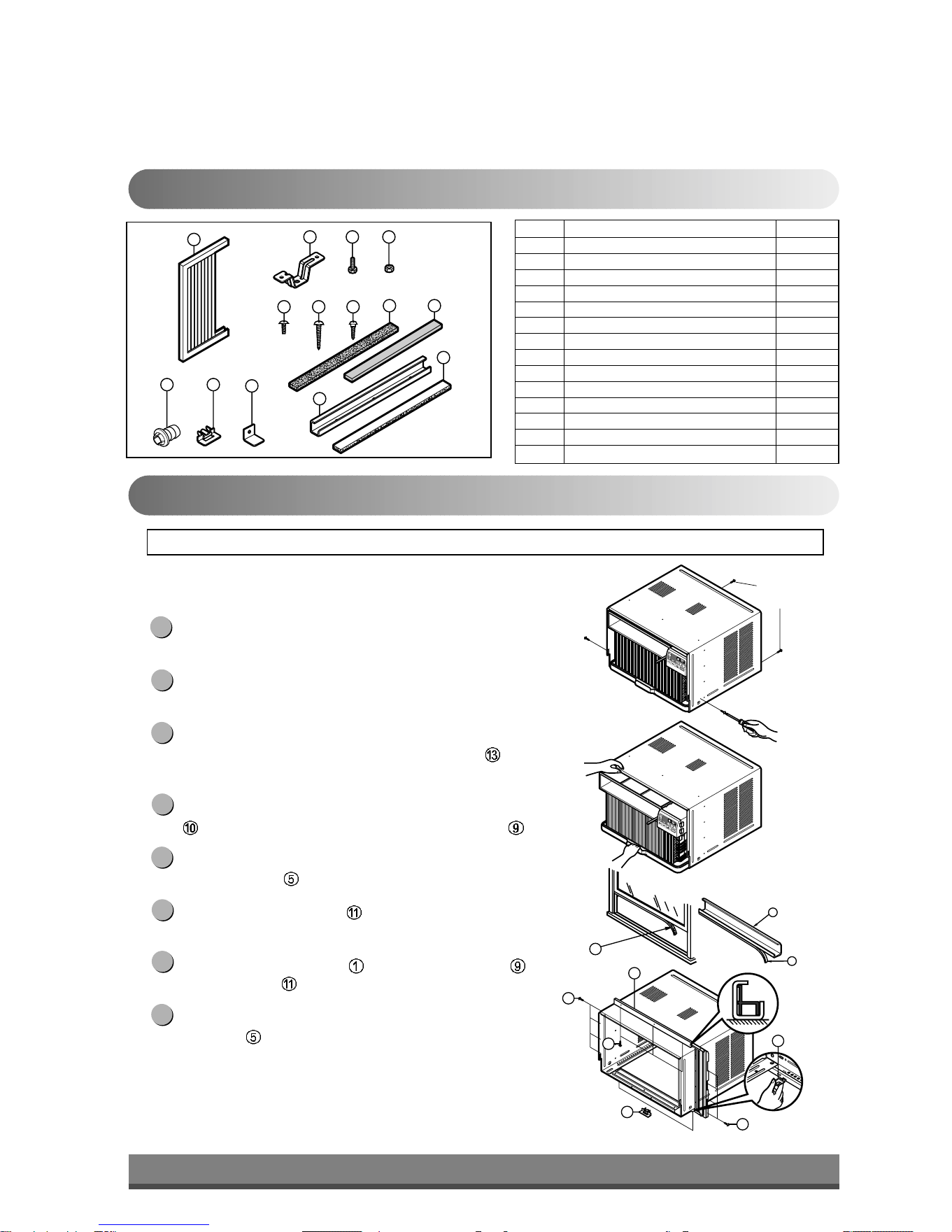
Installation Kits Contents
Suggested Tool Requirements
NO. NAME OF PARTS Q'TY
1 FRAME CURTAIN 2
2 SILL SUPPORT 2
3 BOLT 2
4 NUT 2
5 SCREW (TYPE A) 16
6 SCREW (TYPE B) 3
7 SCREW (TYPE C) 5
8 FOAM-STRIP 1
9 UPPER GUIDE 1
10 FOAM-PE 1
11 FRAME GUIDE 2
12 WINDOW LOCKING BRACKET 1
13 FOAM-PE 1
14 DRAIN PIPE 1
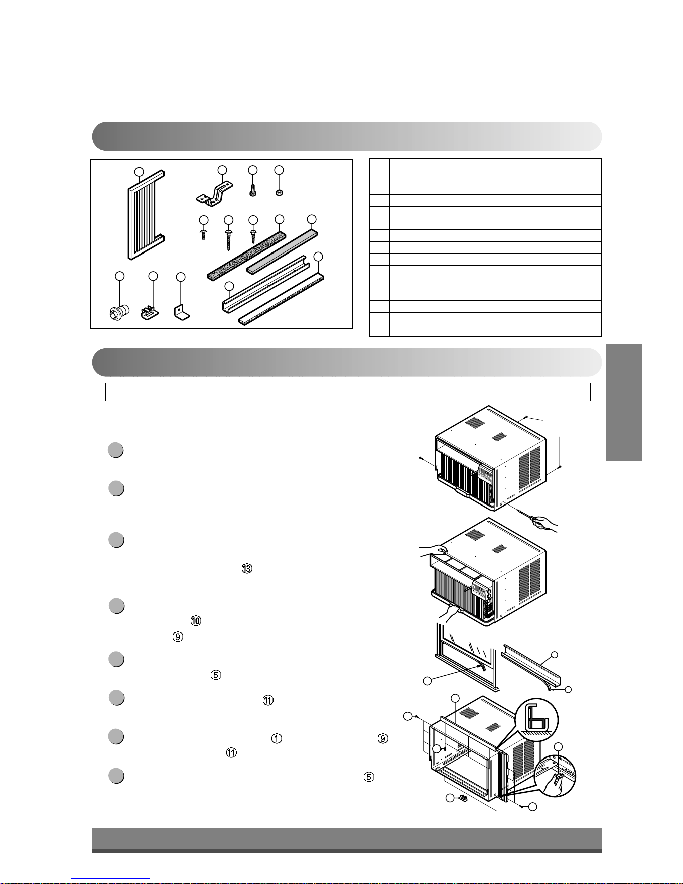
PREPARATION OF CHASSIS
Remove the screws which fasten the cabinet at both
sides and at the back.
Slide the unit from the cabinet by gripping the base pan
handle and pulling forward while bracing the cabinet.
Cut the window sash seal to the proper length.
Peel off the backing and attach the Foam-PE
to the
underside of the window sash.
Remove the backing from the top upper guide Foam-PE
and attach it to the bottom of the Upper Guide .
Attach the upper guide onto the top of the cabinet with 3
Type A screws
.
Insert the Frame Guides into the bottom of the
cabinet.
Insert the Frame Curtain
into the Upper Guide and
Frame Guides .
Fasten the curtains to the unit with 4 Type
A screws
.
8
7
6
5
4
3
2
1
SCREWDRIVER(Philips and Flatead), RULER, KNIFE, HAMMER, PENCIL, LEVEL
Downloaded from www.ManualsFile.com manuals search engine
15
ENGLISH
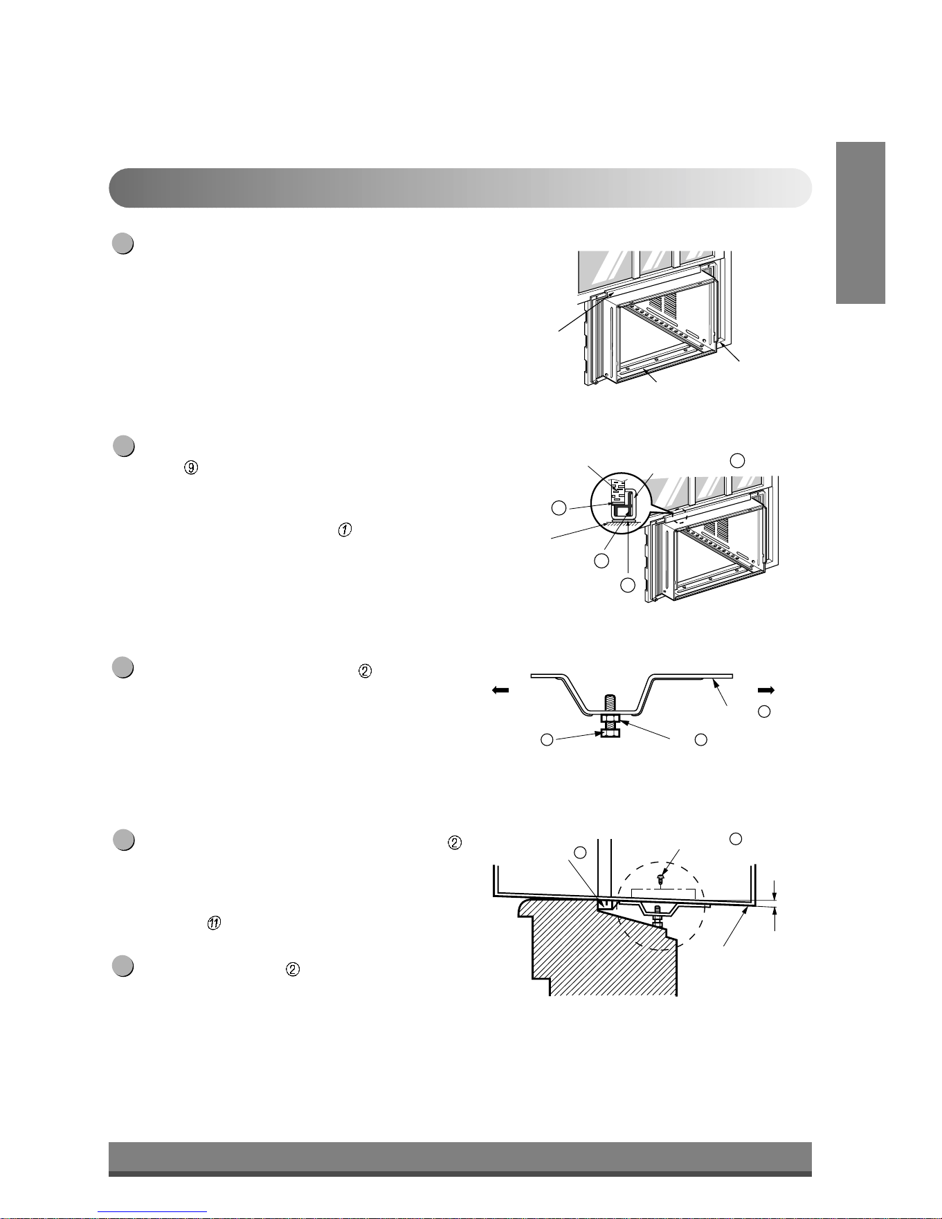
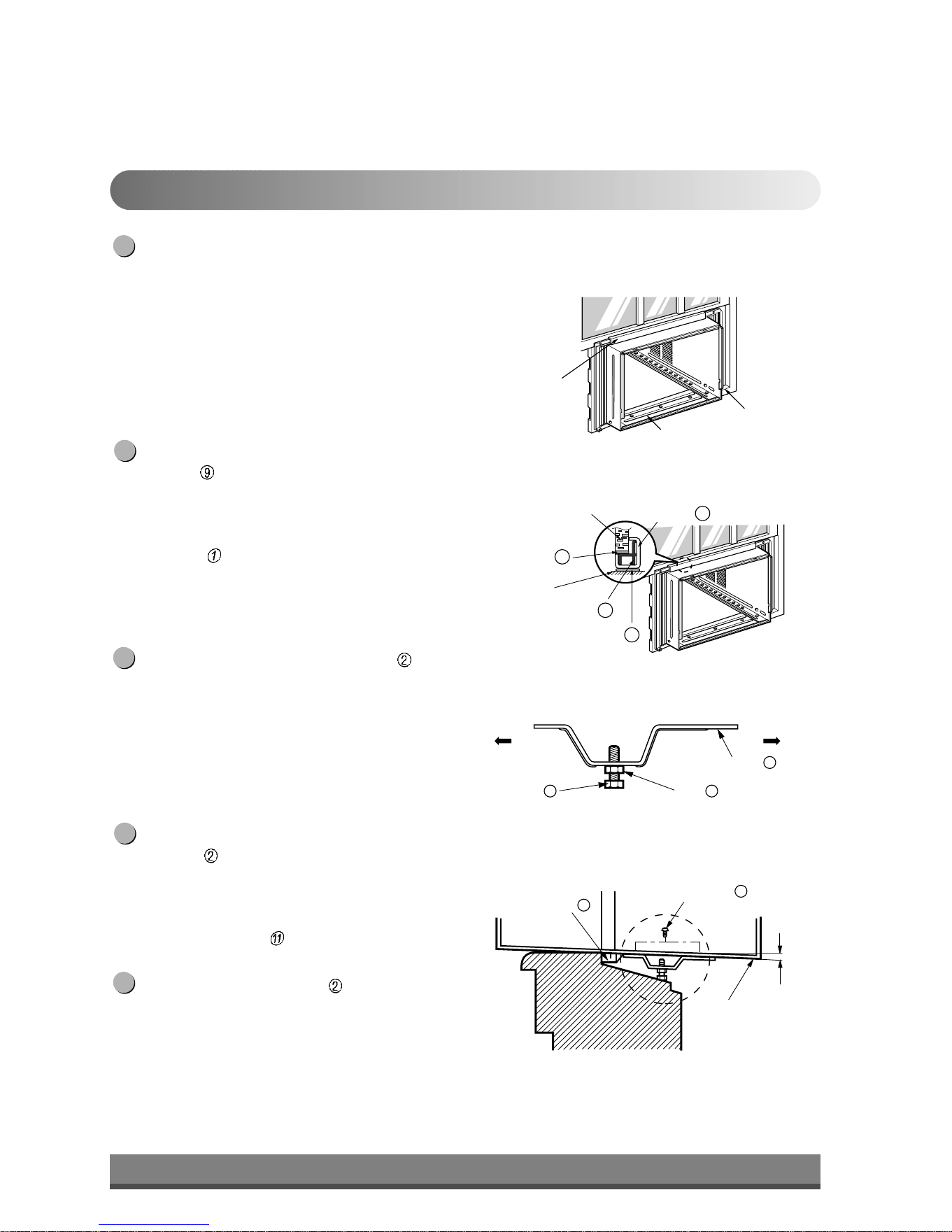
Cabinet Installation
Open the window. Mark a line on center of the
window stool.
Carefully place the cabinet on the window stool and
align the center mark on the bottom front with the
center line marked in the window stool.
Pull the bottom window sash down behind the Upper
Guide
until it meets.
NOTE: Do not pull the window sash down tightly that the
movement of Frame Curtain is restricted.
Loosely assemble the Sill Support using the parts
in Fig. 3.
Select the position that will place the Sill Support
near the outer most point on sill (See Fig. 4)
NOTE: Be careful when you install the cabinet (Frame
Guides
are broken easily).
Attach the Sill Support to the cabinet track hole in
relation to the selected position using 2 Type A
screws in each support (See Fig. 4).
5
4
3
2
1
INDOOR OUTDOOR
Sill Support
2
Nut
4
Bolt
3
INDOOR OUTDOOR
Cabinet
About
1
/2"
Frame Guide
11
Screw(Type A)
5
Upper Guide
Window stool
Front Angle
Window Sash Upper guide
9
Frame Curtain
1
Foam-pe
10
Foam-pe
13
Cabinet
Fig. 1
Fig. 2
Fig. 3
Fig. 4
Downloaded from www.ManualsFile.com manuals search engine
16
Sash track
Front Angle
About
1
/2"
Screw(Type B)
6
Screw(Type B)
6
Sill Support
2
Sill Support
2
Foam-Strip
8
Fig. 5
Type C
7
Fig. 6
Screw(Type A)
Screw
(Type A)
Power cord
Fig. 7
Fig. 8
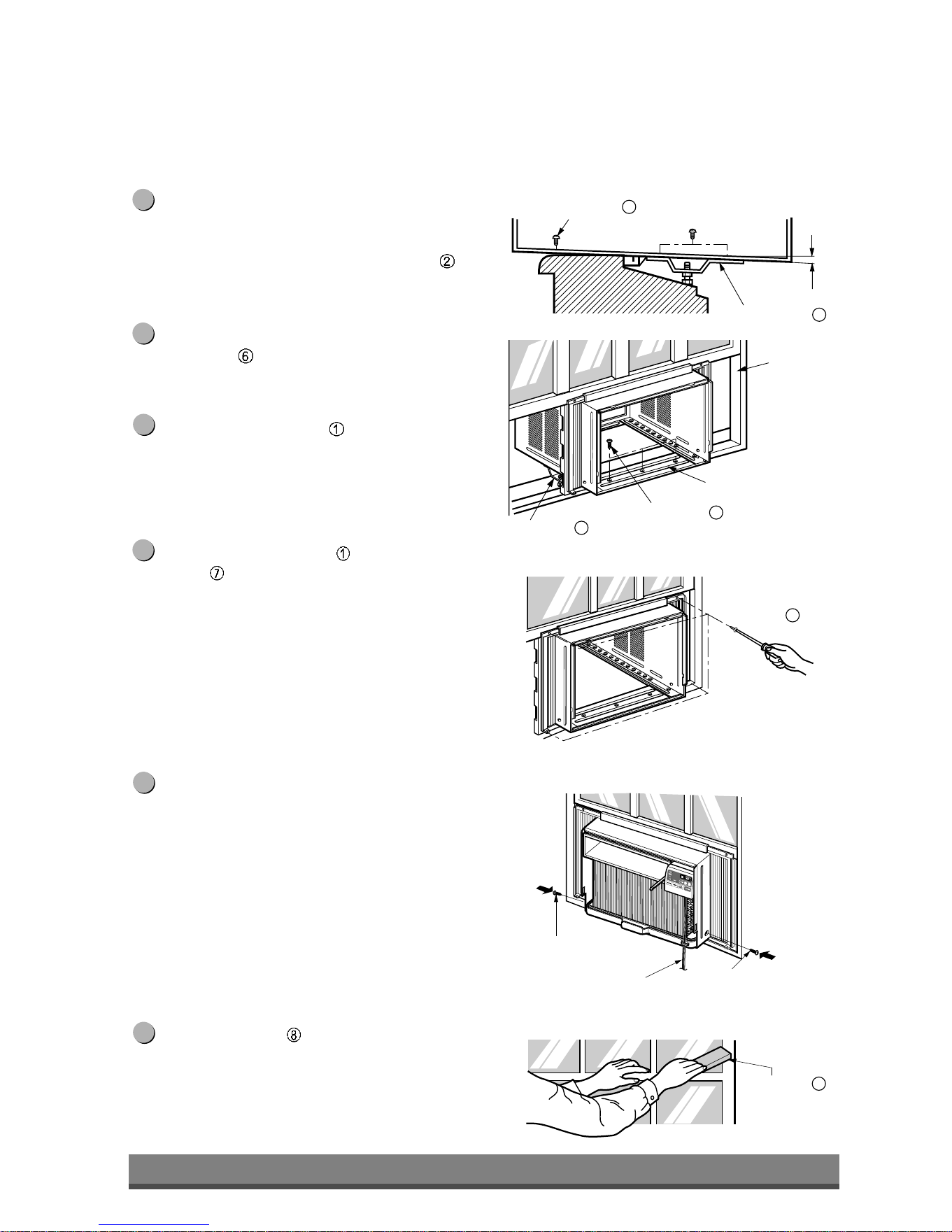
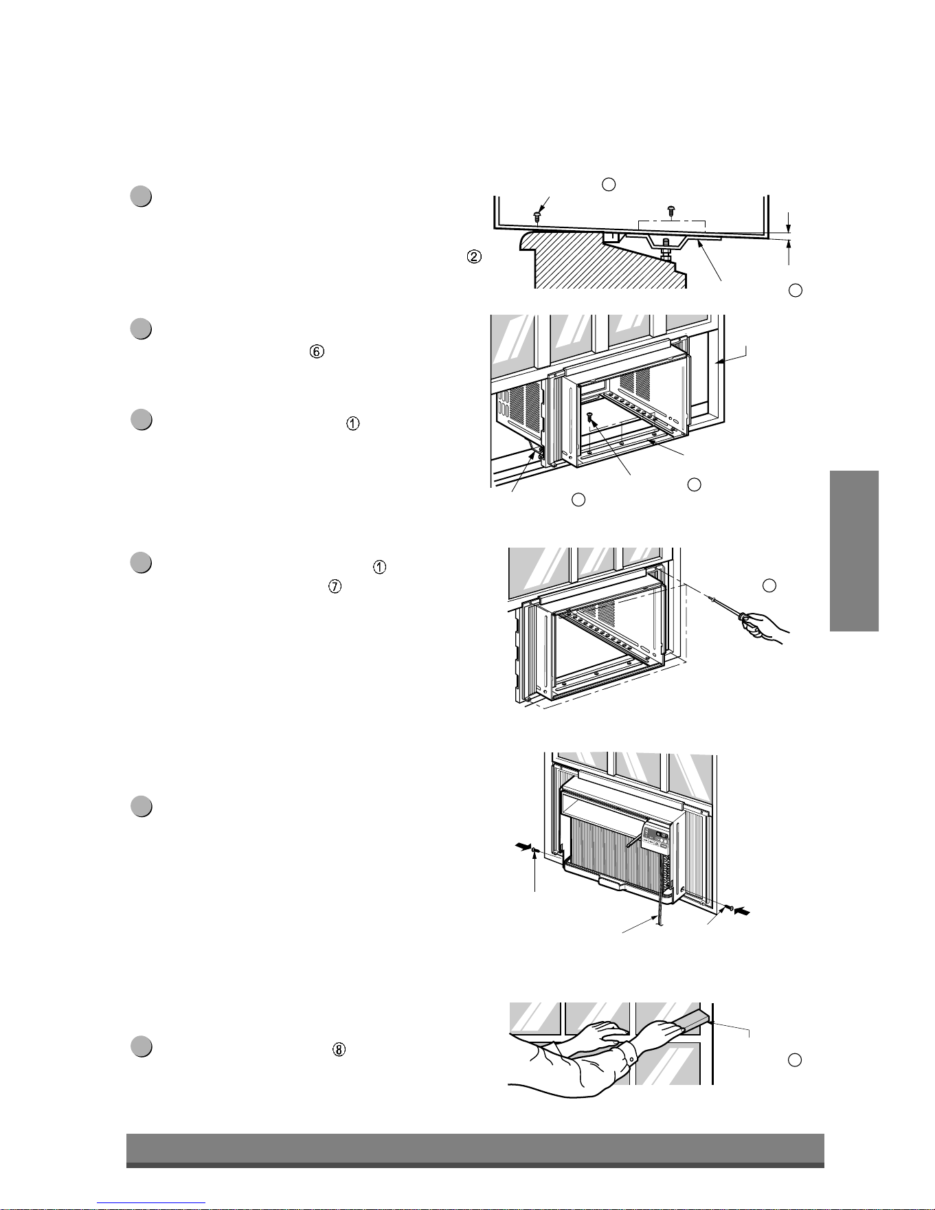
The cabinet should be installed with a very slight tilt
(about 1/2") downward toward the outside
(See Fig. 5).
Adjust the bolt and the nut of Sill Support for
balancing the cabinet.
Attach the cabinet to the window stool by driving
the screws
(Type B: Length 16mm (5/8 inch)
and below.) through the front angle into window
stool.
Pull each Frame Curtain
fully to each window
sash track, and repeat step 2.
Attach each Frame Curtain the window sash using
screws (Type C). (See Fig. 6)
CAUTION: Do not drill a hole in the bottom pan.
The unit is designed to operate with
approximately 1/2" of water in bottom pan.
There is no need to add water if the pan is dry.
Slide the unit into the cabinet. (See Fig. 7)
CAUTION: For security purpose, reinstall screws (Type A)
at cabinet's sides.
Cut the Foam-Strip
to the proper length and insert
between the upper window sash and the lower
window sash. (See Fig. 8)
11
10
9
8
7
6
Downloaded from www.ManualsFile.com manuals search engine
17
ENGLISH
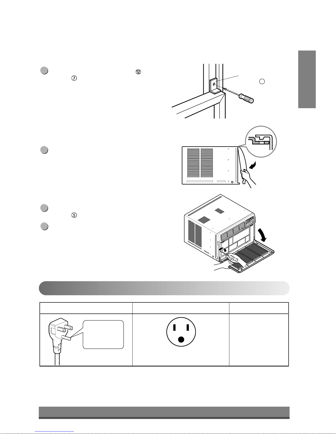
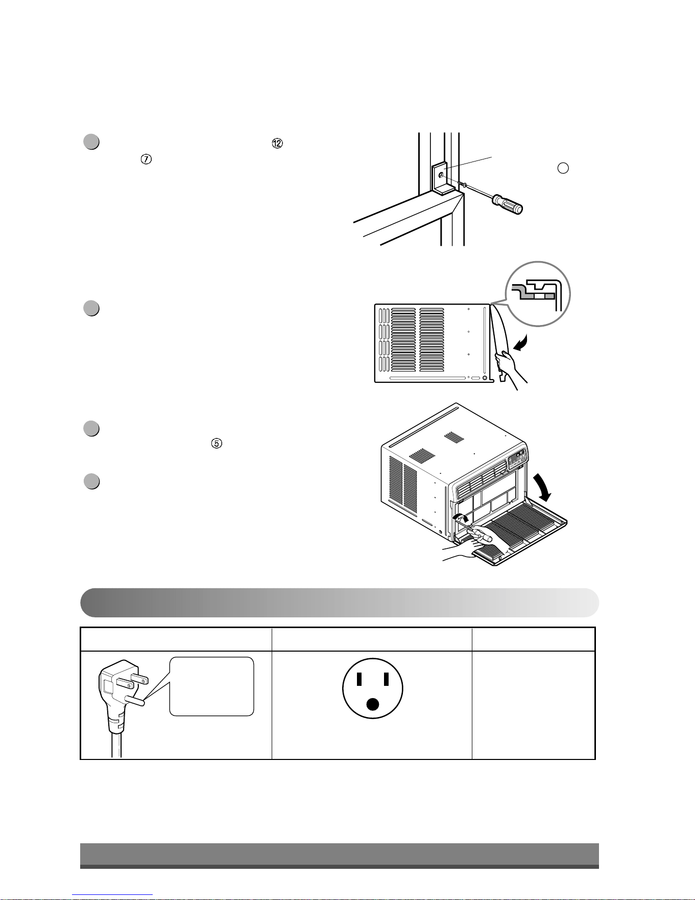
Window locking
bracket
12
Do not under any
circumstances cut
or remove the
grounding prong
from the plug.
Line Cord Plug Use Wall Receptacle Power Supply
Power supply cord with
3-prong grounding plug
Standard 125V, 3-wire grounding
receptacle rated 15A, 125V AC
Use 15 AMP, time
delay fuse or circuit
breaker.
Fig. 9
Fig. 10
Fig. 11
Attach the Window Locking Bracket with a Type
C screw . (See Fig. 9)
Attach the front grille to the cabinet by inserting the
tabs on the grille into the tabs on the front of the
cabinet. Push the grille in until it snaps into place.
(See Fig. 10)
Pull down the inlet grille and secure it with a Type
A screw
through the front grille. (See Fig. 11)
Window installation of room air conditioner is
now completed. See ELECTRICAL DATA for
attaching power cord to electrical outlet.
15
14
13
12
Electrical Data
Use of extension cords
• Because of potential safety hazards, we strongly discourage the use of an extension cord. However, if you wish
to use an extension cord, use a CSA certified/UL-listed 3-wire (grounding) extension cord, rated at 15A, 125V.
Downloaded from www.ManualsFile.com manuals search engine
18
PREFERRED METHOD
Ensure proper ground
exists before use
TEMPORARY METHOD
Adapter plug
Receptacle cover
Metal screw
Fig. 12
Fig. 13
Electrical Safety
IMPORTANT
(PLEASE READ CAREFULLY)
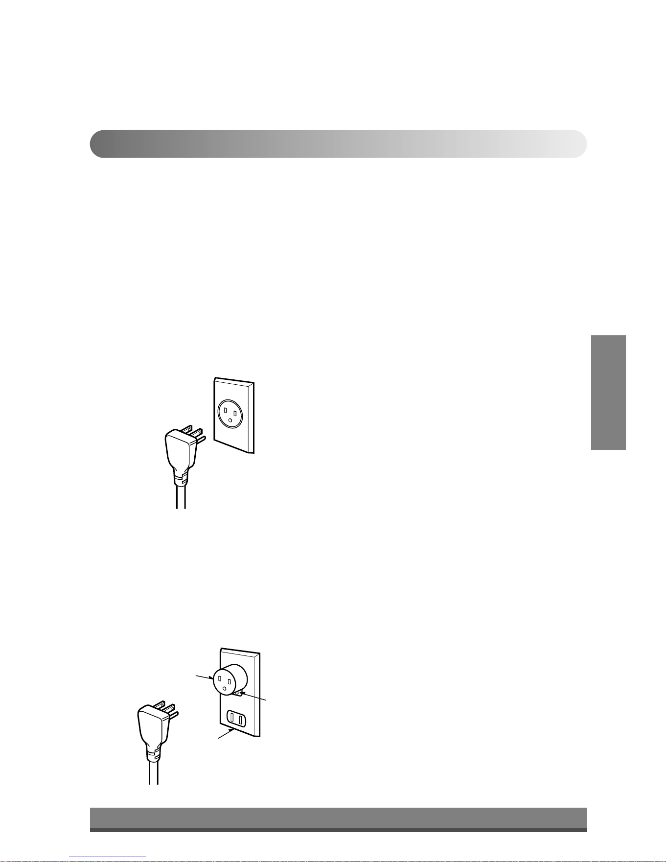
FOR THE USER'S PERSONAL SAFETY, THIS
APPLIANCE MUST BE PROPERLY GROUNDED
The power cord of this appliance is equipped with a
three-prong (grounding) plug. Use this with a standard
three-slot (grounding) wall power outlet (Fig. 12) to
minimize the hazard of electric shock. The customer
should have the wall receptacle and circuit checked by
a qualified electrician to make sure the receptacle is
properly grounded.
DO NOT CUT OR REMOVE THE THIRD (GROUND)
PRONG FROM THE POWER PLUG.
A. SITUATIONS WHEN THE APPLIANCE WILL BE
DISCONNECTED OCCASIONALLY:
Because of potential safety hazards, we strongly
discourage the use of an adapter plug. However, if you
wish to use an adapter, a TEMPORARY
CONNECTION may be made. Use UL-listed adapter,
available from most local hardware stores (Fig. 13).
The large slot in the adapter must be aligned with the
large slot in the receptacle to assure a proper polarity
connection.
CAUTION: Attaching the adapter ground terminal to
the wall receptacle cover screw does not
ground the appliance unless the cover
screw is metal, and not insulated, and the
wall receptacle is grounded through the
house wiring. The customer should have
the circuit checked by a qualified electrician
to make sure the receptacle is properly
grounded.
Disconnect the power cord from the adapter, using one
hand on each. Otherwise, the adapter ground terminal
might break. DO NOT USE the appliance with a
broken adapter plug.
B. SITUATIONS WHEN THE APPLIANCE WILL BE
DISCONNECTED OFTEN.
Do not use an adapter plug in these situations.
Unplugging the power cord frequently can lead to an
eventual breakage of the ground terminal. The wall
power outlet should be replaced by a three-slot
(grounding) outlet instead.
USE OF EXTENSION CORDS
Because of potential safety hazards, we strongly
discourage the use of an extension cord. However, if
you wish to use an extension cord, use a CSA
certified/UL-listed 3-wire (grounding) extension cord,
rated at 15A, 125V.
Downloaded from www.ManualsFile.com manuals search engine
19
Common Problems and Solutions
Common
Issues
Before calling for service, please review the following list of common problems and solutions.
The air conditioner is operating normally when:
• You hear a pinging noise. This is caused by water being picked up by the condenser on rainy days or in highly
humid conditions. This feature is designed to help remove moisture in the air and improve cooling efficiency.
• You hear the thermostat click. This is caused by the compressor cycle starting and stopping.
• You see water dripping from the rear of the unit. Water may be collected in the base pan in highly humid
conditions or on rainy days. This water overflows and drips from the rear of the unit.
• You hear the fan running while the compressor is silent. This is a normal operational feature.
The air conditioner may be operating abnormally when:
Problem Possible Causes What To Do
■ The air conditioner is unplugged or
not plugged in completely
■ The fuse is blown/circuit breaker is
triggered
■ Power failure.
■ Air flow is restricted
■ The THERMOSTAT may not be
set cool enough
■ The air filter is dirty.
■ The air conditioner was just
turned on.
■ Cold air is escaping.
■ Cooling coils are iced up
■ The cooling coils are iced over.
• Make sure the plug is completely plugged into
the outlet
• Check the fuse/circuit breaker box and replace
the fuse or reset the breaker
• In the event of a power failure, set the power
control to OFF. When the power is restored,
wait 3 minutes to restart the air conditioner to
prevent the compressor from overloading
• Make sure there are no curtains, blinds,
furniture or other obstacles in front of the air
conditioner
• Turn the knob to a higher setting. The highest
setting provides maximum cooling
• Clean the filter at least every 2 weeks. Refer to
the “Care and Maintenance” section (p.11) of
the manual.
• After the air conditioner is turned on, you need
to give the air conditioner some time to cool the
room.
• Check for open furnace floor resisters and cold
air returns.
• CLOSE the air conditioner vent
• See Ice appears on the air conditioner below
• Ice may block the air flow and obstruct the air
conditioner from properly cooling the room. Set
the fan at MED or HIGH while setting the
thermostat at 1 or 2 until the ice melts.
The air conditioner
does not operate
at all
Air conditioner
does not cool
Ice appears on the
air conditioner.
ENGLISH
Downloaded from www.ManualsFile.com manuals search engine

2
Manual del usuario del acondicionador de aire tipo Ventana
TABLA DE CONTENIDOS
1. Precauciones de seguridad
2. Instrucciones operativas
3. Cuidado y mantenimiento
4. Instalación de la unidad
5. Problemas habituales
PARA SUS ARCHIVOS
Escriba aquí el modelo y número de serie:
Modelo n°:
Serie n°:
Puede encontrar estos datos en la etiqueta situada en
el lateral de cada unidad.
Nombre del distribuidor:
Fecha de compra:
■
Adjunte su recibo a esta página con la grapadora para
el momento que lo necesite para probar la fecha de su
adquisición o para la validación de la garantía.
LEA ESTE MANUAL
En su interior encontrará muchos consejos útiles sobre la
utilización y mantenimiento de su acondicionador de aire.
Unos pocos cuidados por su parte le pueden ahorrar mucho
tiempo y dinero durante la vida de su acondicionador de aire.
En la tabla de consejos para la solución rápida de problemas
encontrará muchas respuestas a los problemas más
habituales. Si revisa primero nuestra Tabla de Consejos
para la solución rápida de problemas, tal vez no necesite
llamar nunca al servicio técnico.
PRECAUCIÓN
• Póngase en contacto con un técnico del servicio
autorizado para realizar la reparación y mantenimiento
de esta unidad.
• Póngase en contacto con un instalador para realizar la
instalación de esta unidad.
• Cuando se va a cambiar el cable eléctrico, el trabajo de
reemplazamiento debe ser realizado únicamente por
personal autorizado, utilizando las piezas de cambio
genuinas únicamente.
• El trabajo de reemplazamiento debe ser realizado de
acuerdo con el Código Eléctrico Nacional únicamente
por personal autorizado.
ESPAÑOL
Downloaded from www.ManualsFile.com manuals search engine
3
Precauciones
Precauciones de
seguridad
Para prevenir tanto lesiones al usuario u otras personas como daños materiales, es preciso seguir
estas instrucciones.
■ El manejo incorrecto debido a la instrucción ignorada puede causar lesioes o daños cuya
gravedad está clasificada en als siguientes indicaciones.
ADVERTENCIA
PRECAUCION
Este símbolo indica la posibilidad de lesiones mortales o graves.
Este símbolo indica la posibilidad de lesiones o daños materi-ales.
■ El significado de los símbolos utilizados en este manual se indica a continuación.
Asegúrese de no hacerlo.
Asegúrese de seguir las instrucciones.
ADVERTENCIA
■ Instalación
Instale siempre el (los) panel(es) de
expansion.
• No instalarlo puede causar incendio y/o
accidente eléctrico.
No coloque el cable eléctrico cerca de un
calefactor.
• Puede causar incendio y descarga eléctrica.
No use el cable de corriente cerca de gas
inflamable o combustibles tales como
gasolina, benzina, solvente, etc.
• Puede causar explosión o incendio.
No desarme o modifique los productos.
• Puede causar fallos y descarga eléctrica.
Gasoli
n
Downloaded from www.ManualsFile.com manuals search engine
4
■ Funcionamiento
Enchufe la corriente
adecuadamente.
• De otro modo, causará
descarga eléctrica o incendio
debido a la generación de
calor.
No haga funcionar o detenga
la unidad insertando o
tirando del enchufe.
• Causará descarga eléctrica o
incendio debido a la
generación de calor.
No dañe ni use un cable no
especificado.
• Causará descarga eléctrica o
incendio.
No modifique la longitud del
cable de corriente eléctrica.
• Causará descarga eléctrica o
incendio debido a la
generación de calor.
No comparta la salida con
otros artefactos.
• Causará descarga eléctrica o
incendio debido a la
generación de calor.
Siempre enchufe las piezas
eléctricas en una salida
conectada a masa.
• Si no hay conexión a masa,
se puede producir una
descarga eléctrica. (Vea el
Manual de instalación.)
Desenchufe la unidad si se
producen sonidos u olores
extraños en la unidad.
• En caso que no, puede
causar incendio y accidente
de corto circuito.
No use el tomacorriente si
está suelto o dañado.
• Puede causar incendio y
accidente eléctrico.
No haga funcionar la unidad
con las manos húmedas o
en un ambiente húmedo.
• Puede causar descarga
eléctrica.
ESPAÑOL
ON
ON
Downloaded from www.ManualsFile.com manuals search engine
5
No permita la entrada de
agua.
• Puede causar una falla del
motor o una descarga
eléctrica.
Deje la puerta cerrada
mientras está operando el
aire acondicionado.
• Ésta no está diseñado para
enfriar la casa entera.
Ventile antes de hacer
funcionar el acondicionador
de aire cuando sale el gas.
• Puede causar explosión,
incendio, quemaduras.
Nunca toque las piezas de
metal de la unidad cuando
quite el filtro.
• Son filosas y pueden causar
lesiones.
No bloquee la entrada o la
salida de aire.
• Puede causar fallos en la
unidad o accidentes.
Asegúrese de que la caja
externa no está dañada por
los anõs o desgaste.
•
Si se deja la unidad averiada, hay
posibilidad de daños debido a
que esta puede caer. Hay
responsabilidad sobre el daño
debido a falla
del producto.
Al momento de su instalación,
evite que se contacte con los
bordes afilados.
• Hay riesgo de lesiones
personales.
Sostenga el enchufe por el
cuerpo (no del cable)
cuando lo saque.
• Puede causar descarga
eléctrica y daño.
Desconecte el interruptor
principal de energía cuando
no lo esté usando.
• Prevenga un arranque
accidental y la posibilidad de
lesiones.
PRECAUCION
■ Instalación
Bordes
afilados
■ Funcionamiento
Downloaded from www.ManualsFile.com manuals search engine
6
No coloque objetos sobre el
cable de corriente y cuide
que el cable no quede
presionado.
• Hay peligro de incendio o de
descarga eléctrica.
Si entra agua a la unidad, gire
el interruptor principal del
artefacto. Tome contacto con
el centro de servicio después
de desconectar el enchufe del
tomacorriente.
No limpie la unidad de aire
acondicionado con agua.
• Puede entrar agua en la
unidad y disminuir la
aislación. Puede causar una
descarga eléctrica.
Cuando limpie la unidad,
asegúrese primero de que
estén desconectados la
energía y el interruptor.
•
Como el ventilador gira a alta
velocidad cuando está funcionando,
puede causar lesiones.
No coloque una mascota o
una planta donde quede
expuesto al flujo directo de
aire.
• Este puede causar lesiones o
daños en la mascota o la
planta.
No use la unidad para propósitos
especiales tales como animals o
vegetales, máquinas de precision
u objetos de arte.
• Puede causar daño a los
animales o vegetales y
pérdida de objetos.
Siempre asegure los filtros
al insertarlos. Límpielos
cada dos semanas.
• El funcionamiento sin filtros
puede dañar la unidad.
Use una paño suave para
limpiar. No use ceras,
solventes o un detergente
fuerte
•
La unidad del aire acondicionado
puede deteriorarse, cambiar de
color, o desarrollar manchas en
la superficie.
No beba el agua drenada del
acondicionador de aire. No
dirija el flujo de aire sólo a los
ocupantes de la habitación.
• Contiene elementos que
pueden ser nocivos para su
salud. / Esto puede dañar su
salud.
ESPAÑOL
W
a
x
Thinner
• Causará descarga eléctrica
o incendio.
Downloaded from www.ManualsFile.com manuals search engine

7
Previo al funcionamiento
Precauciones de
seguridad
Preparar para el funcionamiento
Contactar un especialista para la instalación.
Coloque el enchufe correctamente.
No comparta la salida con otros artefactos.
No use un cable de extensión.
No arranque/detenga el funcionamiento enchufando/desenchufando el cable de corriente eléctrica.
Si cuerda/tapón se daña, reemplace sólo con una parte autorizada.
6
5
4
3
2
1
Uso
Limpieza y mantenimiento
No use agua para limpiar adentro del acondicionador. La exposición al agua puede destruir la aislación
y esto a su vez provocar una descarga eléctrica.
Cuando limpie la unidad, asegúrese que la corriente y el interruptor estén desconectados. El ventilador
gira a muy alta velocidad cuando está funcionando. Existe la posibilidad de lesionarse si la energía se
conecta accidentalmente cuando esté limpiando las piezas internas de la unidad.
2
1
Servicio
Para reparación y mantenimiento, contacte a su proveedor de servicio.
Estar expuesto al flujo directo de aire por un período largo de tiempo puede constituir un riesgo para su
salud. No exponga a las personas, mascotas o plantas al flujo directo por períodos largos de tiempo.
Debido a la posibilidad de una deficiencia de oxígeno, ventile la habitación cuando utilice al mismo
tiempo estufas u otros aparatos de calefacción.
No use este acondicionador de aire para propósitos determinados no especificados (por ej.: preservar
dispositivos de precisión, alimentos, cachorros, plantas y objetos de arte). Usarlo de esta manera
puede dañar tales elementos.
3
2
1
Downloaded from www.ManualsFile.com manuals search engine
8
Power
Temp
Fan Speed
Timer Mode
'
F
TIMER POWERMODE
TEMP
FAN
SPEED
F1 LOW
F2 MED
F3 HIGH
Dry Timer
Fan
Energy
Saver
Cool
1
2
6
3 45
1
2
3
4
5
Funcionamiento del control remoto
Instrucciones
operativas
El control remoto y el panel de control tendrán un aspecto parecido al de los que aparecen en la
fotografía más abajo.
ESPAÑOL
Downloaded from www.ManualsFile.com manuals search engine
9
ESPAÑOL
Empuje hacia afuera con su pulgar la cubierta en la parte posterior del control
remoto.
Preste atención a la polaridad e inserte dos nuevas baterías AAA 1.5V .
Vuelva a colocar la cubierta
:
No use baterías recargables. Asegúrese que ambas baterías sean nuevas.
• Para evitar que se descarguen, quite las baterías del control remoto si el acondicionador
de aire no va a ser usado por un período largo de tiempo. Mantenga el control remoto
lejos de los lugares húmedos o extremadamente calientes. Para mantener el
funcionamiento óptimo del control remoto, el sensor remoto no debe exponerse a la luz
solar directa.
• El soporte montable del control remoto puede ser montado sobre una pared.
NOTA
3
2
1
Insertar las baterías del control remoto
POWER (encendido)
El funcionamiento se inicia cuando se pulsa esta tecla y se detiene cuando se la presiona nuevamente.
CONTROL DE TEMPERATURA
El termostato monitorea la temperatura de la habitación para mantener la temperatura deseada.
El termostato puede ser colocado entre 60°F~86°F (16°C~30°C).
La unidad toma un promedio de 30 minutos para ajustar la temperatura de la habitación en 1°F.
FUNCIONAMIENTO DEL MODO SELECTOR
Seleccione el modo fresco (cool) para enfriar la habitación.
Seleccione el modo de ahorro de energía para el funcionamiento del ahorro de energía.
Seleccione el modo ventilador (fan) para el funcionamiento del ventilador.
Seleccione el modo seco (dry) para el funcionamiento seco.
SELECTOR DE VELOCIDAD DEL VENTILADOR (FAN SPEED)
Para aumentar la capacidad mientras se refresca, seleccione una mayor velocidad del ventilador.
3 Pasos: High (alta) → Low (baja) → Med (media)
CRONÓMETRO ON/OFF (ENCENDIDO/APAGADO) El cronómetro puede ser colocado para iniciar y detener la unidad
en incrementos por hora (hasta 12 horas).
SENSOR DEL CONTROL REMOTO
6
5
4
3
2
1
Remote Control OperationsFuncionamiento del control remoto
AUTO-ARRANQUE
En caso de fallo de la corriente eléctrica, la unidad funcionará como antes cuando vuelve la
corriente.
Downloaded from www.ManualsFile.com manuals search engine
10
Parte
A
CERRADA VENTILACIÓN ABIERTA
Ajustar la dirección del flujo de aire
Instrucciones
operativas
Control de ventilación
Para máxima eficiencia de frescura, CIERRE la ventilación. Esto permitirá la circulación interna de aire.
ABRA la ventilación para descargar el aire viciado.
Ajustar la dirección del flujo de aire
• Recommended orientation of louvers
Adjust louvers to face upwards when cooling to maximize cooling efficiency.
El flujo de aire puede ser ajustado cambiando la dirección de las rejillas de ventilación del acondicionador de
aire. Esto puede también incrementar la eficacia del acondicionador de aire.
: Antes de usar la función de ventilación, coloque
la palanca de ventilación tirando hacia fuera de
la Parte A y presionándola en su lugar.
NOTA
Adjusting horizontal air flow Adjusting vertical air flow
• Ajustar la dirección del flujo de aire horizontal.
Ajustar las rejillas verticales hacia la izquierda y
derecha cambiará el flujo horizontal.
• Ajustar la dirección del flujo de aire vertical
Ajustar el álabe horizontal hacia arriba y abajo
cambiará el flujo de aire vertical. La aleta puede
ajustarse presionando hacia delante o hacia atrás.
ESPAÑOL
Downloaded from www.ManualsFile.com manuals search engine
11
Caño de drenaje
Tapa de drenaje
Cuidado y mantenimiento
Cuidado y
Mantenimiento
Desconecte la energía y desenchufe la unidad antes de limpiar el acondicionador de aire.
Filtro de Aire
El filtro de aire detrás de la parrilla de entrada debe ser controlado y limpiado por lo menos una vez cada dos
semanas (o cuando sea necesario) para mantener el rendimiento óptimo del acondicionador de aire.
Como quitar el filtro de aire
La rejilla puede ser abierta desde la parte superior
para mantenimiento fácil después de la instalación.
Abra la rejilla de entrada tirando de la puerta
externa en la parte superior de la unidad (basada
en instalación).
Tire de la cuba ligeramente para liberar el filtro.
Tire del filtro en la misma dirección de la abertura.
Limpie el filtro con agua tibia y jabonosa. El agua
debe estar por debajo de los 40°C (104°F).
Enjuague y sacuda suavemente el exceso de agua
del filtro. Déjelo secar antes de colocarlo
nuevamente.
5
4
3
2
1
Drenaje
La bandeja de base puede inundarse debido a un exceso de
humedad. Para drenar el exceso de agua, quite la tapa de drenaje
desde la parte posterior de la unidad y asegure el caño de drenaje.
Cuando presione el caño de drenaje en su lugar, aplique fuerza en la
dirección opuesta a las aletas, para evitar lesionarse.
Downloaded from www.ManualsFile.com manuals search engine
12
ESPAÑOL
4
1
2
3
13
11
14
12
7
10
B
A
6
5
8
9
Cable eléctrica
Cable eléctrica
15
Instalación de la unidad
Instalación de
la unidad
Funciones del producto
1. GABINETE
2. PARRILLA FRONTAL
3. FILTRO DE AIRE
4. TOMA DE AIRE (PARRILLA DE ENTRADA)
5. DESCARGA DE AIRE
6. DEFLECTOR VERTICAL DE AIRE
(ÁLABE HORIZONTAL )
7. EVAPORADOR
8. DEFLECTOR HORIZONTAL DE AIRE (ALABE
VERTICAL )
9. PANEL DE CONTROL
10. CABLE ELÉCTRICA
11. COMPRESOR
12. BANDEJA DE BASE
13. ABRAZADERA
14. CONDENSADOR
15. CONTROL REMOTO
Instalación del cable eléctrica
Puede escoger entre los dos métodos abajo descritos de acuerdo a la forma del taburete de su ventana y su preferencia.
• Aprete el obturador usando 2 hoyos de tornillo, y
saque el cable eléctrico a través de la ranura "A".
• Aprete el obturador usando el hoyo izquierdo de
tornillo, y gire apropiadamente para sacar el cable
eléctrico a través de la ranura "B".
Utilizando la ranura "A" Utilizando la ranura "B"
PRECAUCIÓN: Este dispositivo debe ser instalado de acuerdo con la normas
nacionales de cableado. La información que figura a continuación constituye una guía
para explicar las características del producto.
Downloaded from www.ManualsFile.com manuals search engine
13
23" a 36"
La desviación
saliente
La banda
Dintel
Exterior
Pared Interior
20
1
/12" min.
(sin el marco de la cortina)
15" min
(Con el marco de la cortina)
asiento
Alrededor de
1
/
2
"
30"~60"
Protección
Aire fresco
Cerco
Sobre 20"
Radiación
de calor
Cómo instalar la unidad
Para prevenir la vibración y el ruido, asegúrese que
la unidad esté instalada con seguridad y firmeza.
Instale la unidad donde la luz del sol no caiga
directamente en la misma.
La parte exterior del gabinete debe extenderse
hacia afuera por lo menos a 12" sin obstáculos,
como por ejemplo un cerco o una pared, dentro de
los 20" desde la parte posterior del gabinete
porque evitará la radiación de calor del
condensador.
La restricción del aire exterior reduce en gran parte
la eficiencia de enfriar del acondicionador de aire.
Instale la unidad un poco inclinada para que la parte posterior quede ligeramente más baja que el frente
(alrededor de 1/2"). Esto forzará al agua condensada a fluir hacia el exterior.
Instale la unidad con el fondo aproximadamente 30"~60" por encima del nivel del piso.
5
4
3
2
1
Requisitos de la ventana
: Todas las piezas de soporte deben estar aseguradas con madera fuerte, mampostería, o metal.
• Esta unidad está diseñada para ser instalada en
ventanas dobles basculantes estándar con amplitud de
apertura real desde 23" a 36".
• Las hojas inferiores y superiores de la ventana deben
abrirse lo suficiente para permitir una luz vertical de
15" desde la parte inferior de la hoja superior hasta el
asiento de la ventana.
NOTA
PRECAUCIÓN: Todos los álabes laterales del gabinete deben permanecer expuestos a la
parte exterior de la estructura.
Downloaded from www.ManualsFile.com manuals search engine
1
2 3 4
8 13
10
765
9
12
1114
9
10
13
5
11
11
9
5
5
(TIPO A)
(TIPO A)
Tornillos
de fijación
14
Contenidos de los conjuntos de instalación
Requisitos sugeridos de las ventanas
Nº NOMBRE DE LA PARTE Cantidad
1 MARCO DE LA CORTINA 2
2 DINTEL DE SOPORTE 2
3 PERNO 2
4 TUERCA 2
5 TORNILLO (TIPO A) 16
6 TORNILLO (TIPO B) 3
7 TORNILLO (TIPO C) 5
8 BURLETE DE ESPUMA 1
9GUÍA SUPERIOR 1
10 BURLETE DE ESPUMA-PE 1
11 GUÍA DEL MARCO 2
12
ABRAZADERA de FIJACIÓN A LA VENTANA
1
13 BURLETE de ESPUMA-PE 1
14 CAÑO de DRENAJE 1
PREPARACIÓN DEL CHASIS
Quite los tornillos que unen el gabinete a ambos lados y
a la parte posterior.
Deslice la unidad desde el gabinete asiendo la manija de
la base de la bandeja base mientras con la otra mano
sostiene el gabinete.
Corte el sello de la hoja de la ventana en la medida
adecuada. Quite el recubrimiento del soporte y pegue el
burlete de Espuma-PE
a la cara inferior de la hoja de
la ventana.
Quite el soporte de la guía superior del burlete de
Espuma PE
y péguela a la parte inferior de la guía
superior
.
Fije la guía superior a la parte superior del gabinete con
3 tornillos tipo A
.
Inserte las guías del marco en la parte inferior del
gabinete.
Inserte el marco de la cortina en la guía superior y
las guías del marco .
Fije las cortinas a la unidad con 4 tornillos tipo A .
8
7
6
5
4
3
2
1
DESTORNILLADOR (Philips y Flatead), REGLA, CUCHILLO, MARTILLO, LÁPIZ, NIVEL.
ESPAÑOL
Downloaded from www.ManualsFile.com manuals search engine
ADENTRO AFUERA
Soporte del dintel
2
Tuerca
4
Perno
3
ADENTRO AFUERA
Gabinete
Alrededor de
1
/
2
"
Guía de marco
11
Tornillo(Tipo A)
5
Guía superior
Asiento de la ventana
Angulo frontal
hoja de la ventana
Guía superior
9
Marco de la cortina
1
Burlete de espuma -pe
10
Burlete
de espuma -pe
13
Gabinete
Fig. 1
Fig. 2
Fig. 3
Fig. 4
15
Instalación del gabinete
Abra la ventana. Marque una línea en el centro del
asiento de la ventana.
Coloque cuidadosamente el gabinete sobre el asiento
de la ventana alinee la marca central de la parte
inferior frontal con la línea marcada en el centro del
asiento de la ventana.
Tire la hoja inferior de la ventana detrás de la guía
superior
hasta que se encuentren.
NOTA: No tire hacia abajo la hoja de la ventana de un
modo que impida el movimiento del marco de la
cortina .
Arme de modo flojo el soporte del dintel usando
las partes que se muestran en Fig. 3.
Seleccione la posición en la que colocará el soporte
del dintel
cerca del punto más externo del dintel.
(Ver Fig. 4)
NOTA: Tenga cuidado cuando instala el gabinete (las
guías de marcos
se rompen fácilmente).
Agregue el soporte del dintel al hueco de la guía
del gabinete según la posición seleccionada usando
2 tornillos tipo A en cada soporte (Ver Fig. 4).
5
4
3
2
1
Downloaded from www.ManualsFile.com manuals search engine
Carril de la
hoja de ventana
Ángulo frontal
Aproximadamente
1
/
2
"
Tornillo(Tipo B)
6
Tornillo(Tipo B)
6
Soporte del dintel
2
Soporte del dintel
2
Burlete
de espuma
8
Fig. 5
Tipo C
7
Fig. 6
Tornillo (Tipo A)
Tornillo
(Tipo A)
Cable de alimentación
Fig. 7
Fig. 8
16
El gabinete debe ser instalado con una ligera
inclinación (aproximadamente 1/2") de modo que
el lado externo quede hacia abajo (ver Fig. 5)
Ajuste el perno y la tuerca del soporte al dintel
para equilibrar el gabinete.
Agregue el gabinete al asiento de la ventana
colocando los tornillos (Tipo B: Largo 16mm
5/8 - pulgadas - abajo.) a través del ángulo
frontal en el asiento de la ventana.
Tire cada marco de la cortina completamente
para cada carril de hoja de ventana y repita el paso
2.
Agregue cada marco de la cortina de la hoja de
la ventana usando tornillos
(Tipo C). (ver Fig. 6)
PRECAUCIÓN: No perfore en la bandeja inferior.
La unidad está diseñada para operar con
aproximadamente 1/2" de agua en la
bandeja inferior.
No hay necesidad de agregar agua a la
bandeja si la bandeja está seca.
Deslice la unidad dentro del gabinete. (ver Fig. 7)
PRECAUCIÓN: Para propósitos de seguridad, reinstale
los tornillos (Tipo A) a los lados del
gabinete.
Corte el burlete de espuma
en el largo adecuado
e insértelo entre la hoja superior de la ventana y en
la hoja inferior de la misma. (ver Fig. 8)
11
10
9
8
7
6
ESPAÑOL
Downloaded from www.ManualsFile.com manuals search engine
Abrazadera de fijación
de la ventana
12
Enchufe del cable de línea Use el tomacorriente de pared
Alimentación de energía
Fig. 9
Fig. 10
Fig. 11
Bajo ninguna
circunstancia corte
o quite la clavija
de conexión a
tierra del enchufe.
El cable de alimentación de
energía con enchufe de
conexión a tierra de 3 clavijas
Cable estándar de 125V, 3-hilos
con conexión a masa en un rango
de 15A, 125V AC
Use un fusible de
retardo de 15 AMP,
o un interruptor de
circuito.
17
Agregue la abrazadera de fijación con un tornillo
Tipo C
(ver Fig. 9)
Agregue la parrilla frontal al gabinete insertando
las pestañas en la parrilla dentro de las pestañas
del frente del gabinete. Empuje la parrilla hasta
que se fije en el lugar. (ver Fig.10)
Tire hacia abajo la parrilla de entrada y asegúrela
con un tornillo Tipo A
a través de la parrilla
frontal. (ver Fig. 11)
La instalación del acondicionador de aire de
ventana para habitación está ahora
completada. Ver en DATOS DE ELECTRICIDAD
para unir el cable de alimentación a la salida
eléctrica.
15
14
13
12
Datos sobre electricidad
Uso de los cables de extensión
•
A causa de peligros de seguridad potenciales, desaconsejamos seriamente el uso del cables de extensión.
Sin embargo, si desea usar un cable de extensión, use un cable de extensión CSA certificado/UL-listado 3-hilos
(de conexión a masa), con un rango de 15A, 125V.
Downloaded from www.ManualsFile.com manuals search engine
MÉTODO PREFERIDO
MÉTODO TEMPORARIO
Enchufe adaptador
Cubierta
del tomacorriente
Tornillo de metal
Fig. 12
Fig. 13
Asegúrese de que existe la
descarga correcta a masa
antes de usar
18
Seguridad eléctrica
IMPORTANTE
(POR FAVOR LEA CUIDADOSAMENTE)
PARA LA SEGURIDAD PERSONAL DEL USUARIO,
ESTA UNIDAD DEBE SER CORRECTAMENTE
CONECTADA A MASA
El cable de alimentación de este artefacto está
equipado con un enchufe de tres clavijas (con
conexión a masa). Use éste con una salida en un
tomacorriente estándar de pared con tres ranuras (a
masa) (Fig. 12) para minimizar el peligro de descarga
eléctrica. El usuario debe tener un tomacorriente de
pared y un circuito controlado por un electricista
calificado para asegurarse de que el tomacorriente se
halla debidamente descargado a masa.
NO CORTE O QUITE LA TERCERA CLAVIJA
(MASA )DEL ENCHUFE DE ALIMENTACIÓN DE
ENERGÍA.
A. CIRCUNSTANCIAS EN LAS QUE EL
ARTEFACTO DEBE SER DESCONECTADO
OCASIONALMENTE:
A causa de riesgos potenciales de seguridad,
advertimos seriamente que se debe usar un adaptador
de enchufe. Sin embargo, si desea usar un adaptador,
se puede hacer una CONEXIÓN TEMPORARIA . Use
un adaptador enumerado en UL, la ranura grande en
el tomacorriente para asegurar una conexión de
polaridad correcta.
PRECAUCIÓN: Agregar el adaptador con terminal a
masa al tornillo de la cubierta del
tomacorriente no descarga el artefacto
a masa a menos que el tornillo de la
cubierta sea de metal y no se
encuentre aislado, y el tomacorriente
se halle conectado a masa a través del
cableado de la casa. El usuario debe
hacer controlar el circuito por un
electricista calificado para asegurarse
que el tomacorriente se halla
debidamente conectado a masa.
Desconecte el cable de alimentación del adaptador,
usando una mano en cada uno. De otro modo, la
terminal a masa del adaptador puede romperse.
NO USE el artefacto con un adaptador al enchufe roto.
B. CIRCUNSTANCIAS EN LAS QUE EL
ARTEFACTO DEBE SER DESCONECTADO A
MENUDO.
No use un adaptador al enchufe en estas
circunstancias.
Desenchufar el cable de alimentación frecuentemente
puede llevar a una rotura eventual del polo a masa.
El tomacorriente de pared debe ser reemplazado por
otro de tres ranuras.
USE DE CABLES DE EXTENSIÓN
A causa de riesgos de seguridad potenciales,
desaconsejamos seriamente el uso de cables de
extensión. No obstante si desea utilizar un cable de
extensión, use un cable de extensión CSA certificado
/listado en UL de 3 polos (a masa), con un rango de
15A, 125V.
ESPAÑOL
Downloaded from www.ManualsFile.com manuals search engine
29
19
Problemas y soluciones habituales
Problemas
habituales
Antes de llamar al servicio, tenga a bien revisar la siguiente lista de problemas y sus soluciones.
El acondicionador de aire está funcionando normalmente cuando:
• Escucha un sonido metálico. Lo causa el agua que recoge el condensador en días lluviosos o en condiciones
de mucha humedad. Esta característica está diseñada para ayudar a quitar la humedad en el aire y mejorar la
capacidad de enfriamiento.
• Oye un clic en el termostato. Lo causa el ciclo del compresor que comienza y se detiene.
•
Ve gotear agua de la parte posterior de la unidad. El agua puede ser recogida en la bandeja de base en
condiciones de mucha humedad o días de lluvia. Esta agua desborda y gotea desde la parte posterior de la unidad.
• Oye funcionar el ventilador mientras el compresor está silencioso. Esto es una característica operativa normal.
El acondicionador de aire puede estar funcionando anormalmente cuando:
Problema Causas posibles Qué hacer
■ El acondicionador de aire está
desenchufado o no bien enchufado
■ El fusible está fundido / el disyuntor
está interrumpido
■ Corte de corriente
■ El flujo de aire está disminuido
■ El TERMOSTATO puede no estar
colocado en el fresco suficiente
■ El filtro de aire está sucio.
■ El acondicionador de aire se acaba
de encender.
■ El aire frío se escapa.
■ Los serpentines de enfriamiento
están congelados
■ Los serpentines de enfriamiento
están cubiertos de hielo.
• Asegúrese que el enchufe está completamente
enchufado dentro del tomacorriente
• Compruebe el fusible /la caja del disyuntor y
reemplace el fusible o vuelva el disyuntor a su
lugar.
• En el caso de un corte de corriente, coloque el
control de encendido en OFF. Cuando se haya
restaurado la corriente, espere durante 3 minutos
para volver a hacer funcionar el acondicionador de
aire para prevenir la sobrecarga del compresor.
• Asegúrese que no haya cortinas, persianas,
muebles u otros obstáculos frente al
acondicionador de aire
• Gire la perilla a una posición más alta. Mientras
más alto esté mayor será el frío proporcionado.
• Limpie el filtro al menos una vez cada dos
semanas. Refierase a la sección “Cuidado y
mantenimiento” (p.11) del manual.
• Después que se enciende el acondicionador de
aire, debe darle un tiempo al acondicionador de
aire para enfriar la habitación.
• Busque alguna hornalla de resistencia encendida y
el aire frío vuelve.
• CIERRE la ventilación del acondicionador de aire
• Vea Aparece hielo sobre el acondicionador de
aire abajo
• El hielo puede bloquear la corriente de aire e
impedir que el acondicionador de aire enfríe
correctamente la habitación. Coloque la velocidad
del ventilador en MED o ALTA (HIGH) mientras
coloca el termostato en 1 o 2 hasta que el hielo se
funda.
El acondicionador
de aire no funciona
para nada
El acondicionador
de aire no enfría
Aparece hielo sobre
el acondicionador
de aire
Downloaded from www.ManualsFile.com manuals search engine

WARRANTY PERIOD:
HOW SERVICE IS HANDLED:
The warranted labor covers the cost of In-Home Service on all
parts including the compressor.
THIS LIMITED WARRANTY DOES NOT APPLY TO:
CUSTOMER INTER-ACTIVE CENTER NUMBERS:
To Prove Warranty Coverage
To Obtain Nearest Authorized Service Center or Sales
Dealer, or to Obtain Product, Customer, or Service
Assistance
LG ROOM AIR CONDITIONER LIMITED WARRANTY
-
USA
Labor: 2 Years from the Date of Purchase.
Parts: 2 Years from the Date of Purchase.
Compressor: 5 Years from the Date of
Purchase.
LG Electronics Inc. will repair or at its option replace, without charge, your product if it proves to be defective in
material or workmanship under normal use during the warranty period set forth below, effective from the date of
original consumer purchase of the product. This limited warranty is good only to the original purchaser of the product
and effective only when used in the United States including Alaska, Hawaii, and U.S. Territories.
1. Service trips to your home to deliver, pick up, and/or install the product, instruct, or replace house fuses or
correct wiring, or correction of unauthorized repairs; and
2. Damages or operating problems that result from misuse, abuse, operation outside environmental
specifications or contrary to the requirements or precautions in the Operating Guide, accident, vermin,
fire, flood, improper installation, acts of God, unauthorized modification or alteration, incorrect electrical
current or voltage, or commercial use, or use for other than intended purpose.
3. Therefore, the cost of repair or replacement of such a defective product shall be borne by the consumer.
Retain your Sales Receipt to prove date of purchase.
A copy of your Sales Receipt must be submitted at
the time warranty service is provided.
Call 800-984-7469, 24 hrs a day, 7 days per week.
Press the appropriate option, and please
have your product type (AIR CONDITIONER),and
ZIP/postal code ready.
P/No.: 3828A20437E Printed in China
THIS WARRANTY IS IN LIEU OF ANY OTHER WARRANTIES, EXPRESS OR IMPLIED, INCLUDING WITHOUT LIMITATION, ANY
WARRANTY OF MERCHANTABILITY OR FITNESS FOR A PARTICULAR PURPOSE. TO THE EXTENT ANY IMPLIED WARRANTY IS
REQUIRED BY LAW, IT IS LIMITED IN DURATION TO THE EXPRESS WARRANTY PERIOD ABOVE. LG WILL NOT BE LIABLE FOR
ANY CONSEQUENTIAL, INDIRECT, OR INCIDENTAL DAMAGES OF ANY KIND, INCLUDING LOST REVENUES OR PROFITS, IN
CONNECTION WITH THE PRODUCT. SOME STATES DO NOT ALLOW LIMITATION ON HOW LONG AN IMPLIED WARRANTY
LASTS OR THE EXCLUSION OF INCIDENTAL OR CONSEQUENTIAL DAMAGES, SO THE ABOVE LIMITATIONS OR EXCLUSIONS
MAY NOT APPLY TO YOU.
Call 1-877-714-7486 and choose the appropriate prompt. Please
have product type (Room Air Conditioner), model number, serial
number, and ZIP/postal code ready.
Downloaded from www.ManualsFile.com manuals search engine

