AI
Ii®
C N ITIONE
IN
Please read the operating instructions and safety precautions
carefu/y and thoroughly before installing and operating your
room air conditioner.
M NUEL 'UTILI
CII oE= ,o_UI
ION
Veuilez/re atentivement et en entier ce guide d'ullsation
et [es mesures de securite ci-inc[uses avant de proceder &
rinstalation et au fonctionnement de votre clmalseur.
AI N
ICI
Por favor lea las instrucciones de operaci6n y las precauciones
de seguridad cuidadosa y totalmente antes de insta[ar y operar
su acondicionador de aire de ventana.
MODEL, MODELE, MODELO: HBLG1200H
Manufactured by LG Emectronics
FEATURES 2
SAFE_¢ PRECAUTIONS 3
OPERATING ...................................................................................................................................... 5
F UNCTI,ON ........................................................................................................................................ 5
VENTILATION .................................................................................................................................. 6
TO CONTROL AIR DIRECTION ................................................................................................... 6
HOW TO SECURE THE DRAIN PiPE .......................................................................................... 6
AIR FILTER CLEANING ............................................................................................................... 7
HOW TO USE THE REVERSIBLE INLET GRILLE ...................................................................... 7
ELECTRICAL DATA ........................................................................................................................... 8
BEFORE CALLING FOR SERVICE ................................................................................................... 8
INSTALLATION INSTRUCTIONS ......................................................................................................... 9
ELECTR ICAL SAFETY. ..................................................................................................................... 13
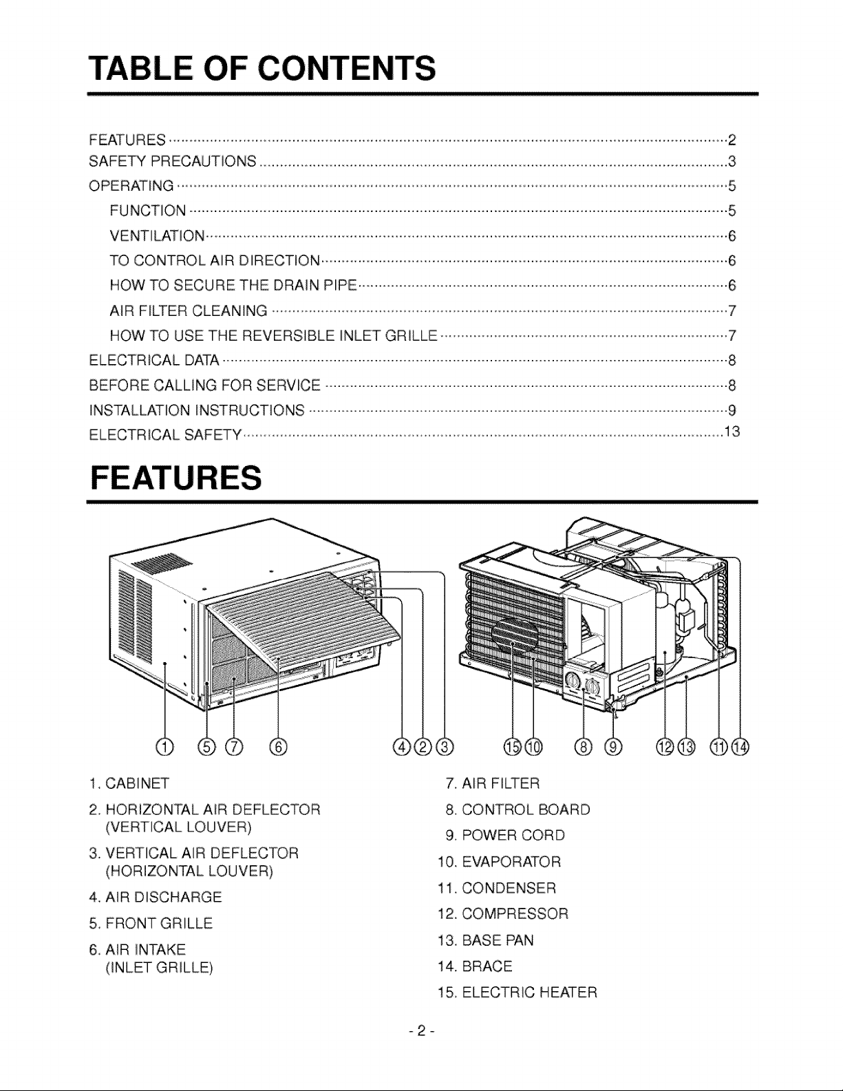
1, CABINET
2, HORIZONTAL AIR DEFLECTOR
(VERTICAL LOUVER)
3, VERTICAL AIR DEFLECTOR
(HORIZONTAL LOUVER)
4. AiR DISCHARGE
5, FRONT GRILLE
6, AIR INTAKE
(INLET GRILLE)
7, AIR FILTER
8, CONTROL BOARD
9, POWER CORD
10. EVAPORATOR
11. CONDENSER
12. COMPRESSOR
13. BASE PAN
14. BRACE
15, ELECTRIC HEATER
To prevent injury tothe user or other people and property damage, the,foliowing instructions must be fol-
lowed.
m incorrect operation due to ignoring ofinstruction wilJcause harm or damage The seriousness is classified
by the following indications,
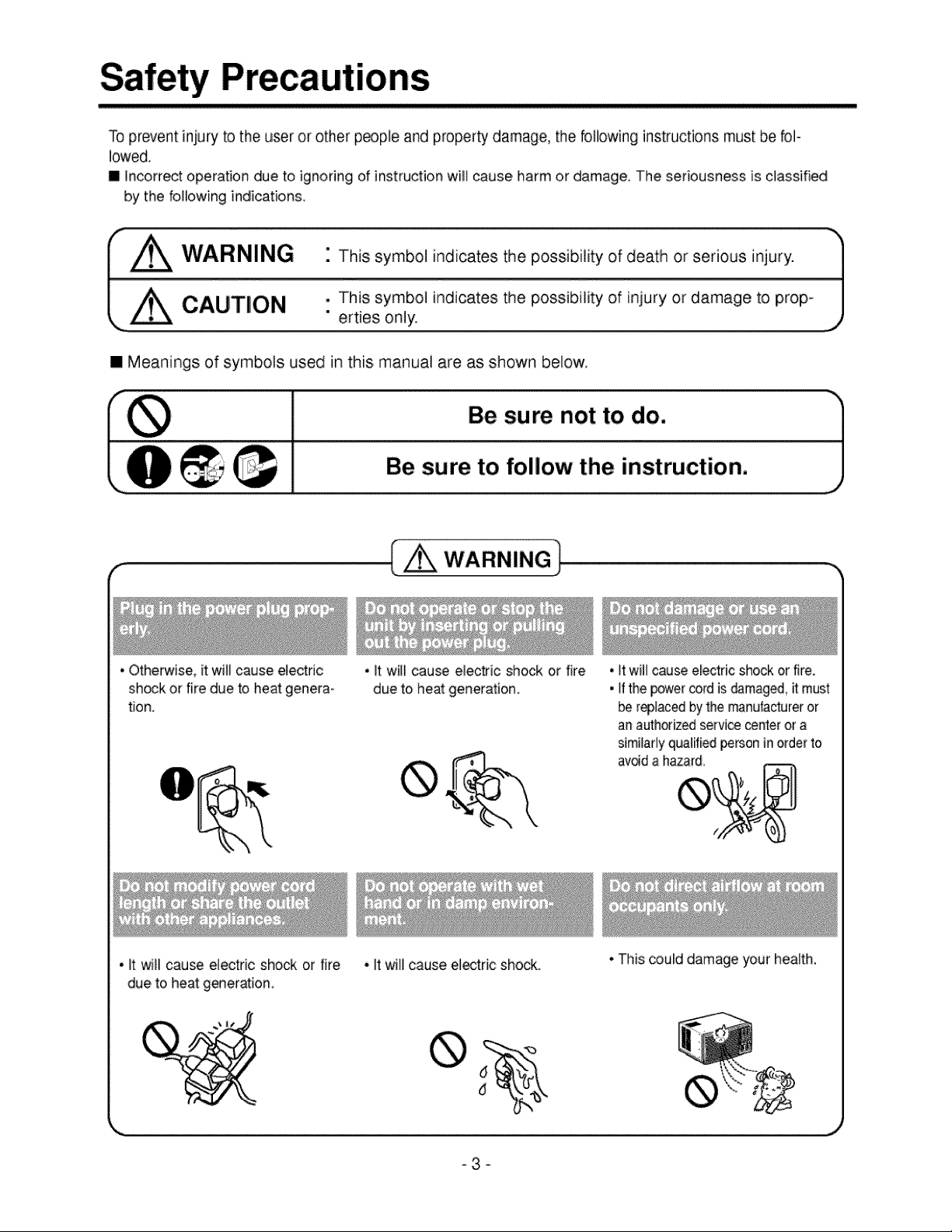
I Z_ WARNING " This symbol indicates the possibility of death or serious injury:
_ CAUTION , This symbol indicates the possibility of injury or damage to prop-
" erties only.
[] Meanings of symbols used in this manual are as shown below,
Be sure not to do.
_ Be sure to follow the instruction.
• Otherwise, it will cause electric
shock or fire due to heat genera-
tion.
. _twill cause electric shock or fire
due to heatgeneration.
•_twill cause e_ectric shock or fire,
•If the _er _rd isdamaged, it must
be r_laced by the manufacturer or
anauthorized service center or a
similarly qualified personJnorder to
avoid ahazard.
. _twill cau_ ellectdcshock or fire
due to heatgeneration.
• itwillcause el_tric: shoals,.
• This coulddamage your health.
°3-
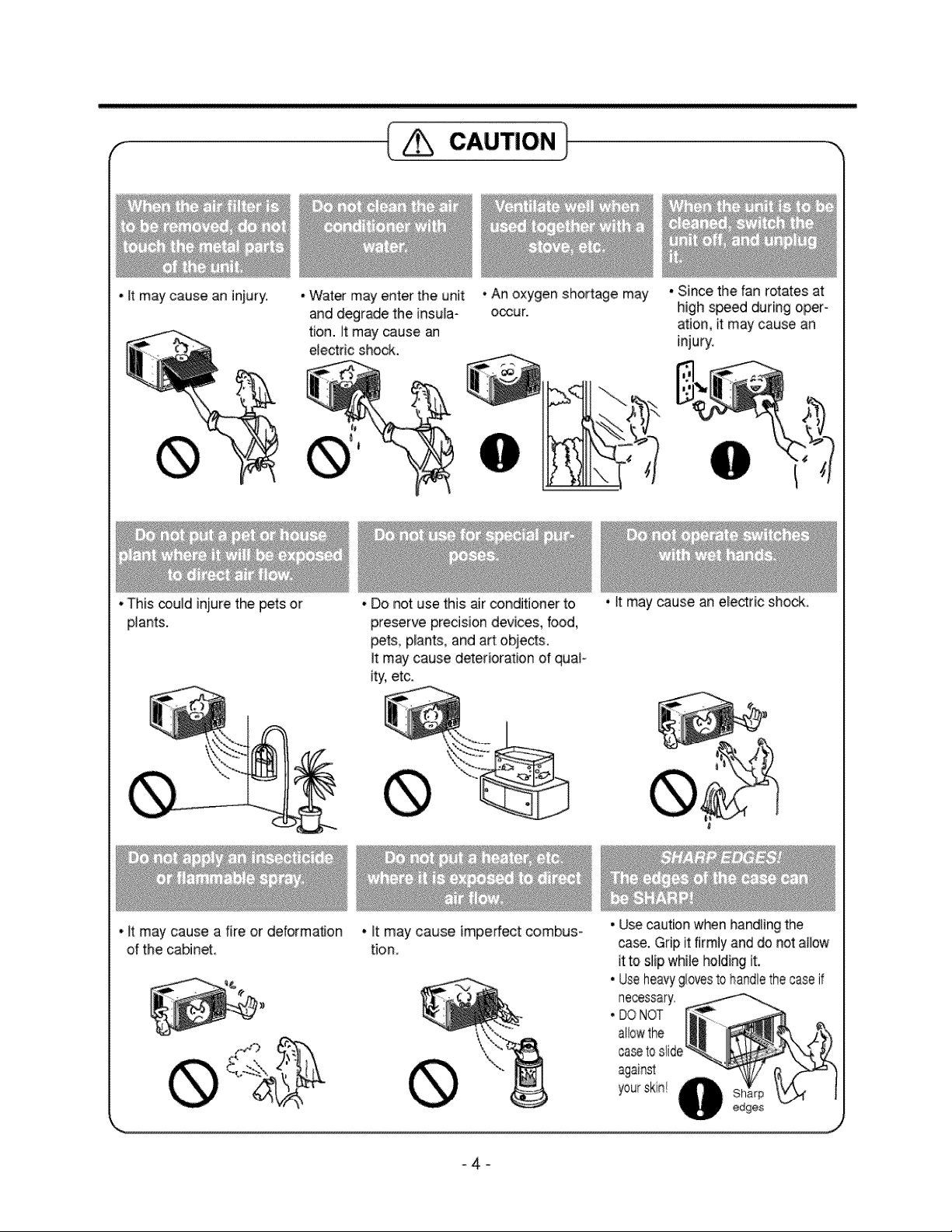
- Itmay cause an iniury. •'Water may enter the unit
• This could injure thepets or
plants.
and degrade the insula-
tion. It may cause an
electric shock.
• It may cause a fire or deformation
ofthe cabinet
• An oxygen shortage may
o_ur.
• Sincethefanrotates at
high speed during oper-
ation, it may cause an
injury.
• Donot use this air conditioner to
preserve precision devices, food,
pets, p_ant&and art:obje_s.
It may cause deterioration ofquaF
ity, etc.
• It may cause imperfect combus-
tion,
• It may cause an ele_ric shock,
• Usecautionwhenhandlingthe
case.Gripitfirmly and do notallow
ittoslip white holdingit,
• Useheavy#lovesto handlethecaseif
necessary.
• DONOT
allowthe
caseto slide
-4-
OPERATING
•WARNING
To reduce the risk of fire, electric shock, or injury to persons, read the IMPORTANT SAFETY
INSTRUCTIONS before operating this appliance.
• CAUTION
When the air conditioner has been performing its cooling operation and is turned off or set to the fan
position, wait at least 3 minutes before resetting to the cooling operation again.
FUNCTION
O
Warmer Cooler _ _
BEFORE RESTARTING
Thermostat WAIT THREEMINUTES Operation
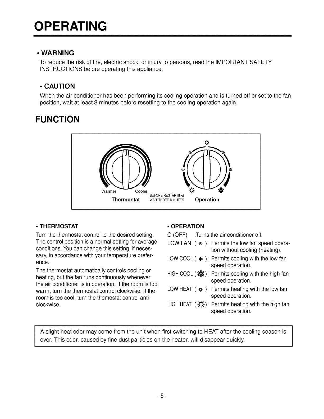
• THERMOSTAT
Turn the thermostat control to the desired setting.
The centrol position is a normal setting for average
conditions. You can change this setting, ifneces-
sary, in accordance with your temperature prefer-
ence.
The thermostat automatically controls cooling or
heating, but the fan runs continuously whenever
the air conditioner is in operation. If the room is too
warm, turn the thermostat control clockwise. If the
room is too cool, turn the themostat control anti-
clockwise.
• OPERATION
O(OFF) :Turns
LOW FAN ( e ):
LOWCOOL( _ ) :
HIGH COOL (_):
LOWHEAT ( -_ ):
HIGH HEAT (-}_):
the air conditioner off.
Permits the low fan speed opera-
tion without cooling (heating).
Permits cooling with the low fan
speed operation.
Permits cooling with the high fan
speed operation.
Permits heating with the low fan
speed operation.
Permits heating with the high fan
speed operation.
A slight heat odor may come from the unit when first switching to HEAT after the cooling season is
over. This odor, caused by fine dust particles on the heater, will disappear quickly.
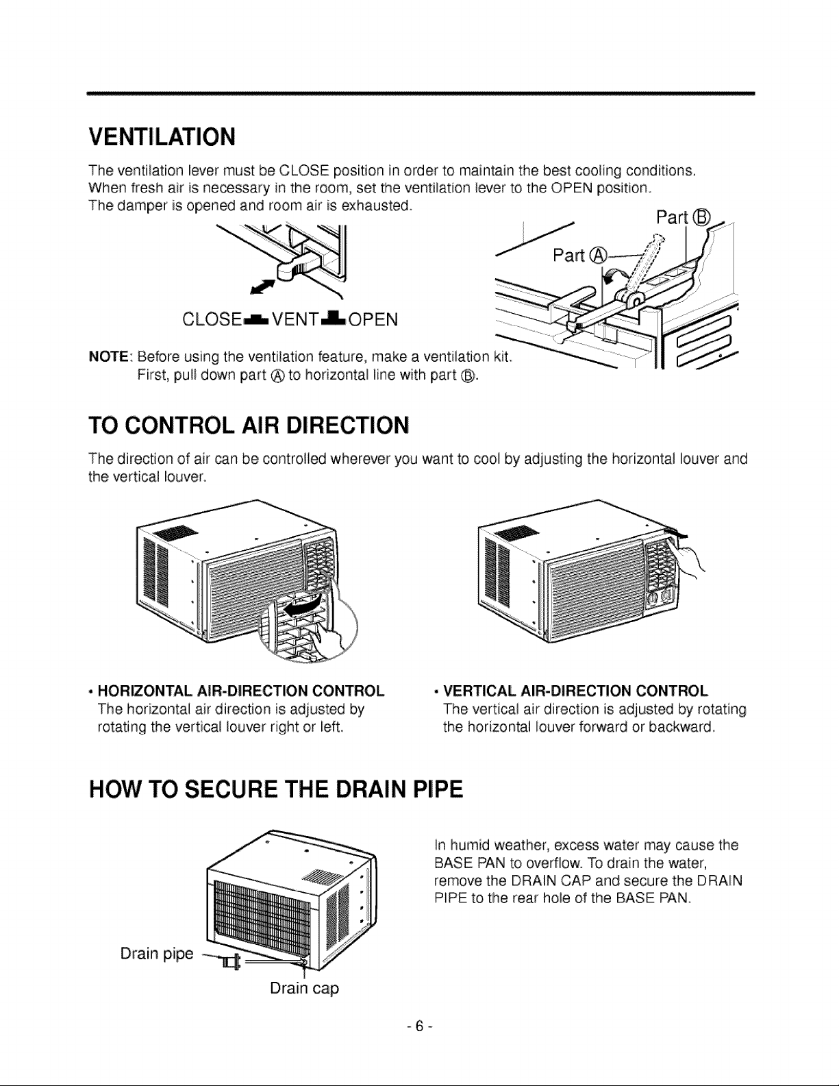
Theventilationlevermustbe CLOSEpositionin orderto maintainthebestcoolingconditions.
Whenfreshair is necessaryinthe room,settheventilationleverto theOPENposition.
Thedamperis openedand roomair is exhausted. Part
NOTE: Before using the ventilation feature, make a ventilation kit.
First, pull down part @ to horizontal line with part @.
TO CONTROL AIR DIRECTION
The direction of air can be controlled wherever you want to cool by adjusting the horizontal louver and
the vertical louver.
• HORIZONTAL AIR-DIRECTION CONTROL
The horizontal air direction is adiusted by
rotating the vertical louver right or left.
. VERTICAL AIR-DIRECTION CONTROL
The vertical air direction is adjusted by rotating
the horizontal louver forward or backward,
HOW TO SECURE THE DRAIN PIPE
In humid weather, ex_ss water may cause the
BASE PAN to ovedlow. To drain the water,
remove the DRAIN CAP and secure the DRAIN
PIPE to the rear hole of the BASE PAN.
Drain pipe -_
Drain cap
°6-
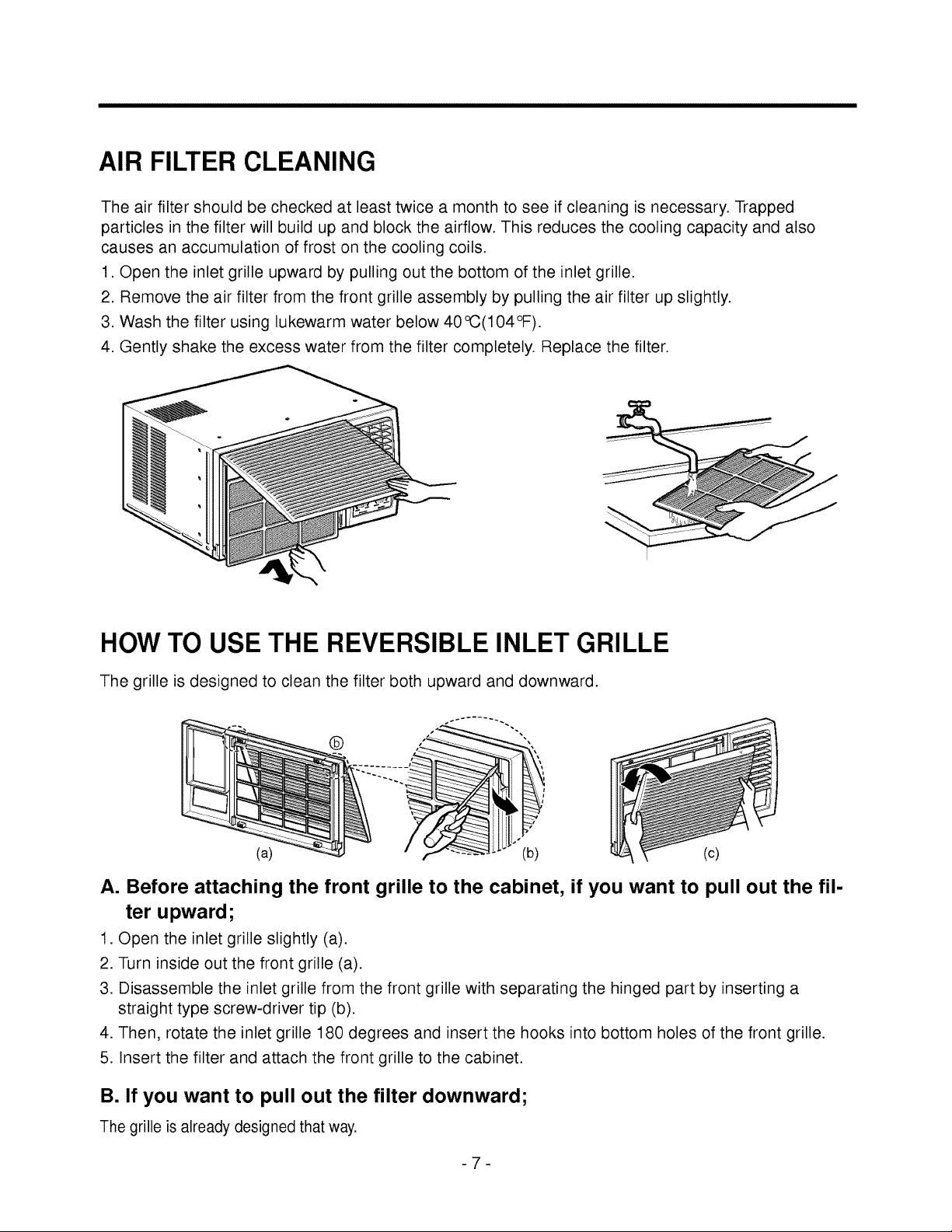
AIR FILTER CLEANING
The air filter should be checked at least twice a month to see if cleaning is necessary. Trapped
particles in the filter will build up and block the airflow. This reduces the cooling capacity and also
causes an accumulation of frost on the cooling coils.
1. Open the inlet grille upward by pulling out the bottom of the inlet grille.
2. Remove the air filter from the front grille assembly by pulling the air filter up slightly.
3. Wash the filter using lukewarm water below 40°C(104°F).
4. Gently shake the excess water from the filter completely. Replace the filter.
HOW TO USE THE REVERSIBLE INLET GRILLE
The grille is designed to clean the filter both upward and downward.
®
(a) (b) (c)
A. Before attaching the front grille to the cabinet, if you want to pull out the fil-
ter upward;
1. Open the inlet grille slightly (a).
2. Turn inside out the front grille (a).
3. Disassemble the inlet grille from the front grille with separating the hinged part by inserting a
straight type screw-driver tip (b).
4. Then, rotate the inlet grille 180 degrees and insert the hooks into bottom holes of the front grille.
5. Insert the filter and attach the front grille to the cabinet.
B. If you want to pull out the filter downward;
The grille isalready designed that way.
ELECTRICAL DATA
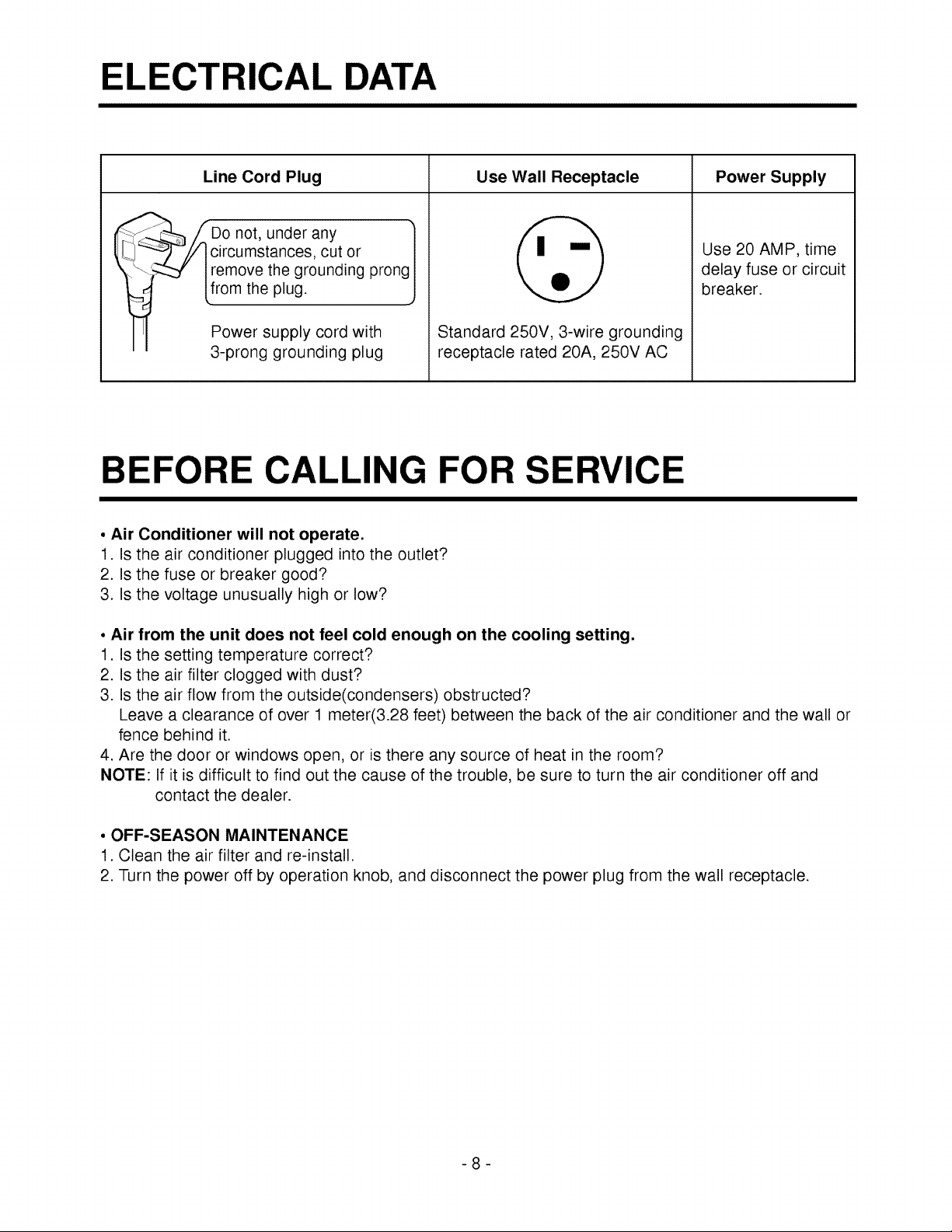
Line Cord Plug
DirOcnOt,under any
umstances, cut or
remove the grounding prong
Lfrom the plug.
Power supply cord with
3-prong grounding plug
Use Wall Receptacle Power Supply
Standard 250V, 3-wire grounding
receptacle rated 20A, 250V AC
Use 20 AMP, time
delay fuse or circuit
breaker.
BEFORE CALLING FOR SERVICE
, Air Conditioner will not operate.
1. Is the air conditioner plugged into the outlet?
2. Is the fuse or breaker good?
3. Is the voltage unusually high or low?
• Air from the unit does not feel cold enough on the cooling setting.
1. Is the setting temperature correct?
2. Is the air filter clogged with dust?
3. Is the air flow from the outside(condensers) obstructed?
Leave a clearance of over 1 meter(3.28 feet) between the back of the air conditioner and the wall or
fence behind it.
4. Are the door or windows open, or is there any source of heat in the room?
NOTE: If it is difficult to find out the cause of the trouble, be sure to turn the air conditioner off and
contact the dealer.
° OFF-SEASON MAINTENANCE
1. Clean the air filter and re-install.
2. Turn the power off by operation knob, and disconnect the power plug from the wall receptacle.
INSTA I
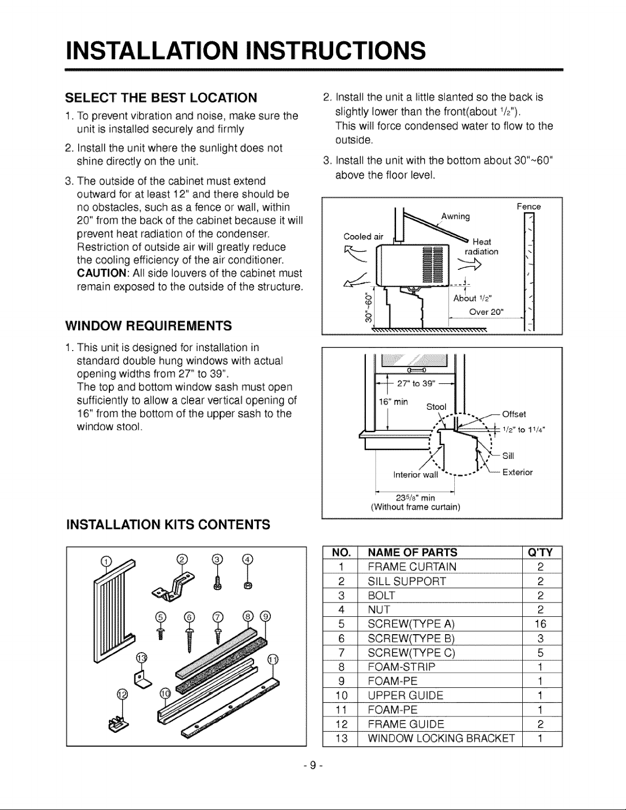
SELECT THE BEST LOCATION
1.To prevent vibration and noise, make sure the
unit isinstalled securely and firmly
2. Install the unit where the sunlight does not
shine directly on the unit.
3. The outside of the cabinet must extend
outward for at least I2" and there should be
no obstacles, such as a fence or wall, within
20" from the back of the cabinet because it will
prevent heat radiation of the condenser.
Restriction of outside air will greatly reduce
the cooling efficiency of the air conditioner.
CAUTION: All side louvers of the cabinet must
remain exposed to the outside of the structure,
WINDOW REQUIREMENTS
1. This unit is designed for installation in
standard double hung windows with actual
opening widths from 27" to 39",
The top and bottom window sash must open
sufficiently to allow a clear vertical opening of
16" from the bosom of the upper sash to the
window stool_
INSTALLATION KITS CONTENTS
2 Install the unit a little slanted so the back is
slightly lower than the front(about !/2").
This will force condensed water to flow to the
outside_
3_ Install the unit with the bosom about 30"~60 ''
above the floor level.
_nterior wall
I
235/8" rain
(Wffhout frame cumin)
Extedor
NAME OF PARTS
FRAME CURTAIN
SILL SUPPORT
BOLT
NUT
SCREW(TYPE A)
NO,
1
2
3
4
5
6
7
8
9
10
11
12
13
SCREW(_PE C)
FOAM-STRIP
FOAM-PE
UPPER GUIDE
FOAM-PE
FRAME GUIDE
WINDOW LOCKING BRACKET
2
2
2
2
16
3
5
1
1
1
1
2
1
SUGGESTED TOOL REQUIREMENTS
SCREWDRIVER(+,-), RULLER, KNIFE, HAMMER,
PENCIL,
LEVEL
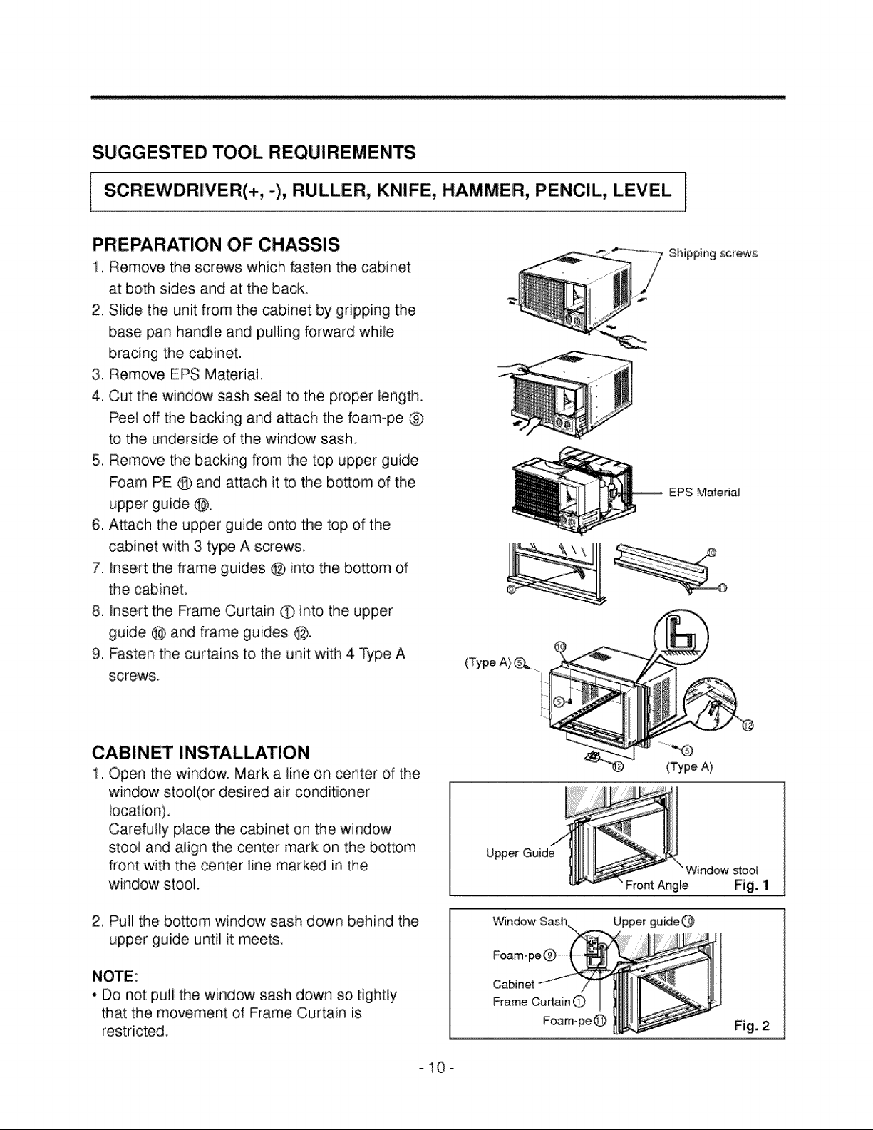
PREPARATION OF CHASSIS
1, Remove the screws which fasten the cabinet
at: both sides and at the back.
2. Slide the unit from the cabinet by' gripping the
base pan handle and pulling forward while
bracing the cabinet.
3. Remove EPS Material.
4, Cut the window sash seal to the proper length.
Peel off the backing and attach the foam-pc @
to the underside of the window sash.
5, Remove the backing from the top upper guide
Foam PE @ and attach it to the bosom of the
upper guide Q,
6. A_ach the upper guide onto the top of the
cabinet with 3 type A screws.
7. insert the frame guides @ into the bottom of
the cabinet.
8. insert the Frame Curtain O) into the upper
guide @ and frame guides @.
9, Fasten the curtains to the unit with 4 Type A
screws.
(Type A}_. i
Shipping screws
EPS Matedal
CABINET INSTALLATION
1. Open the window. Mark a line on center of the
window stool(or desired air conditioner
location).
Carefully place the, cabinet on the window
stool and align the center mark on the bottom
front with the _nter line marked in the
window stool.
2, Pull the bottom window sash down behind the
upper guide until it meets.
NOTE:
• Do not puli the window sash down so tightly
that the movement of Frame Curtain is
restricted.
(Type A)
Upper Guid_indow ;_gll
Window Upper guide
Foam-
Fig. 2
-10-
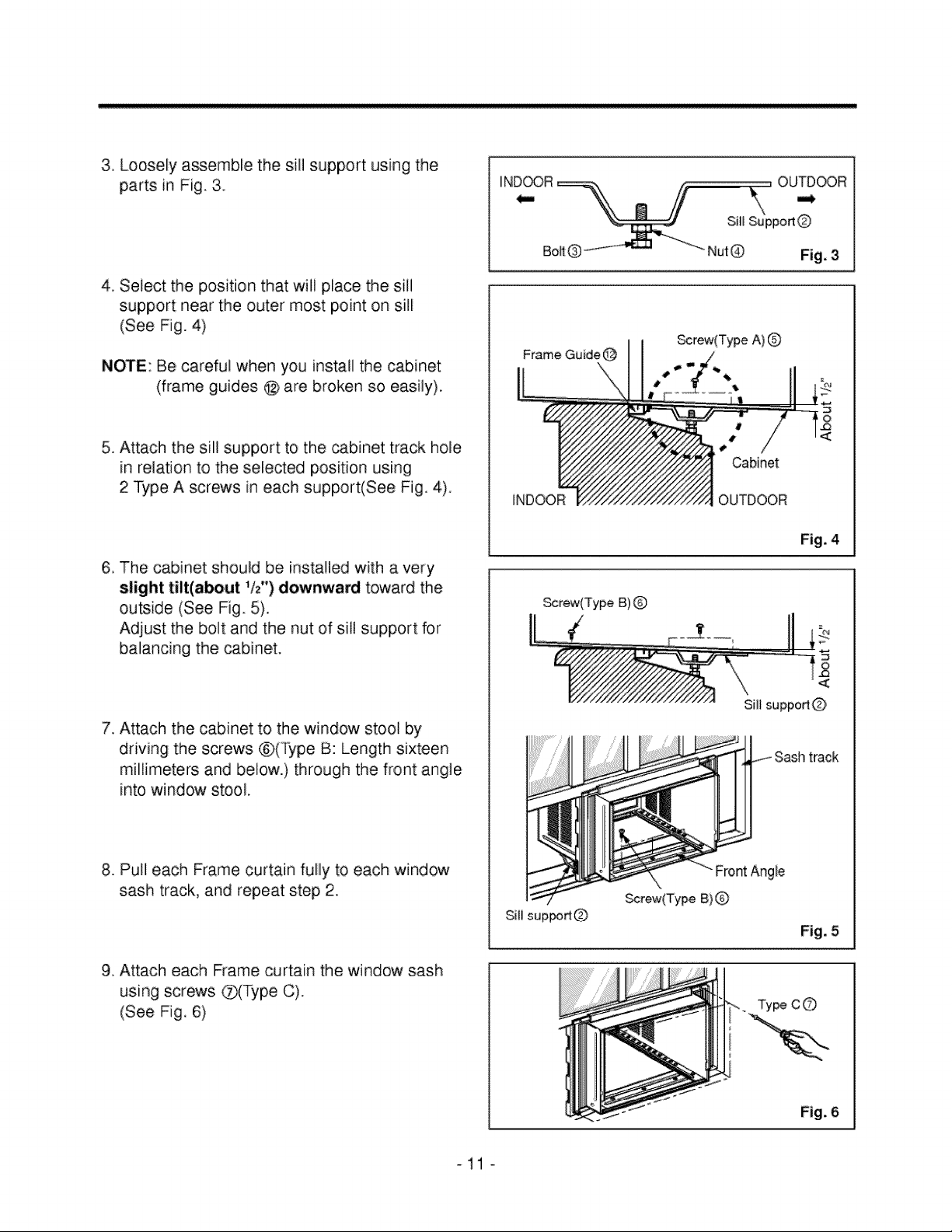
3. Loosely assemble the sill support using the
parts in Fig. 3.
4, Select the position that will place the sill
support near the outer most point on sill
(See Fig. 4)
NOTE: Be, careful when you install the cabinet
(frame guides @ are broken so easily).
5. Attach the sill support to the cabinet track hole
in relation to the selected position using
2 Type A screws in each support(See Fig. 4).
6. The cabinet should be installed with a very
slight tilt(about 1/£) downward toward the
outside (See Fig. 5).
Adjust the bolt and the nut of sift support for
balancing the, cabinet.
7. Attach the cabinet to the window stool by
driving the screws ®(Type B: Length sixteen
millimeters and below.) through the front angle
into window stool,
8. Pull each Frame curtain fullly to each window
sash track, and repeat step 2.
9. Attach each Frame curtain the window sash
using screws Q(Type C).
(See Fig, 6)
NutQ
F_me Guide @
INDOOR
_rew(Type A)@
11,
i,
Cabinet
OUTDOOR
brew(Type B)Q
Sill suppod(_)
FrontAngle
Screw(Type B)
Fig, 3
Fig. 4
Sill supp,ortQ
Fig. 5
c©
-11 o
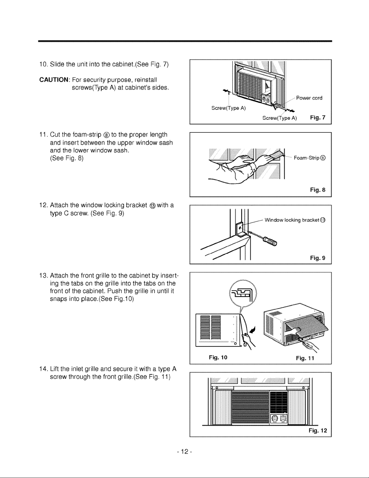
10.Slidethe unitintothecabinet.(SeeFig.7)
CAUTION:Forsecuritypurpose,reinstall
screws(TypeA) at cabinet'ssides.
11,Cutthe foamostnp® to theproperlength
andinsertbetweentheupperwindowsash
andthe lowerwindowsash.
(SeeFig.8)
12.Attachthewindowlockingbracket@witha
typeC screw.(SeeFig.9)
Screw(Type A}
z
Screw(Type A)
.......Power cord
Fig. 7
Foam-S_rip
Fig. 8
locking bracket@
Fig, 9
13. Attach the front grille to the cabinet by insert-
ing the tabs on the grille into the tabs on the
front of the cabinet. Push the grille in until it
snaps into pLace.(See Fig. 10)
14. Lift the inlet grille and secure it with a type A
screw through the front griHe.(See Fig. 11)
..............................................
Fig, i0
Fig. 11
Fig. 12
_12o
ELECTRICAL SAFETY
• ELECTRICAL SAFETY
IMPORTANT GROUNDING INSTRUCTIONS
Air conditioner has a three-prong grounding plug on its
power supply cord, which must be plugged into prop-
erly grounded three-prong wall receptacle foryour pro-
tection against possible shock hazard.
FUSE - Use a time-delay fuse or circuit breaker. Refer
toserial plate for proper power supply requirements.
230, 208, and 230/208 VOLTUNITS
These units are equipped with a three-prong ground-
ing plug on the power supply cord, which must be
plugged into a matching properly grounded three-
prong wall receptacle foryour protection against possi-
ble shock hazard. If such an outlet is not present, one
must be installed by a qualified electrician in accor-
dance with the National Electrical Code and local
codes and ordinances.
NOTE: DO NOT USEAN EXTENSION CORD
ON230, 208, AND 230/208 VOLTUNITS.
-13-
CARACTERISTIQUES 14
MESURES DE SE_CURITE 15
FONCTIONNEMENT ................................................................................................................... 17
LES COMMANDES ......................................................................................................................... 17
LA VENTILATION ........................................................................................................................... 18
AJUSTER LA DIRECTION D'AIR ................................................................................................ 18
COMMENT UTILISER LE TUYAU D'EVACUATION .................................................................... 18
NETTOYAGE DU FILTRE A AIR ................................................................................................... 19
COMMENT UTIMSER LA GRILLE D'ADMISSION REVERSIBLE .............................................. 19
DONNEES SU R L'ELEOTRIOITE .................................................................................................... 20
AVANT DE FAIRE APPEL A UN TECHNICEN ................................................................................ 20
INSTRUCTIONS POUR D'INSTALLATION ......................................................................................... 21
MESURES DE SECURITE ELECTRIQUES .................................................................................... 25
f
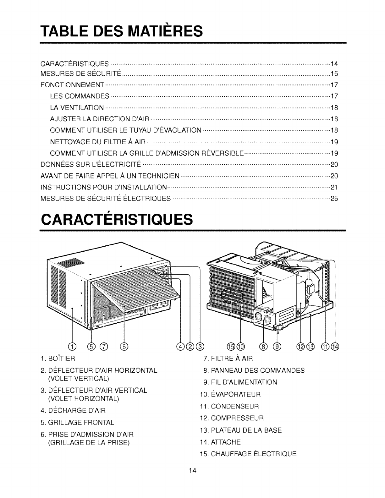
1, BOtTlER
2 DEFLECTEUR D'AIR HORIZONTAL
(VOLET VERTICAL)
3. DEFLECTEUR D'AIR VERTICAL
(VOLET HORIZONTAL)
4. DECHARGE D'AIR
5, GRILLAGE FRONTAL
6. PRISE D'ADMISSION D'AIR
(GRILLAGE DE LA PRISE)
7, FILTRE A AIR
8, PANNEAU DES COMMANDES
9. FIL D'ALIMENTATLON
10. EVAPORATEU R
11. CONDENSEUR
12. COMPRESSEUR
13, PLATEAU DE LA BASE
14. ATTACHE
15, C HAUFFAGE ELECTRIQUE
-14-
Mesures de "
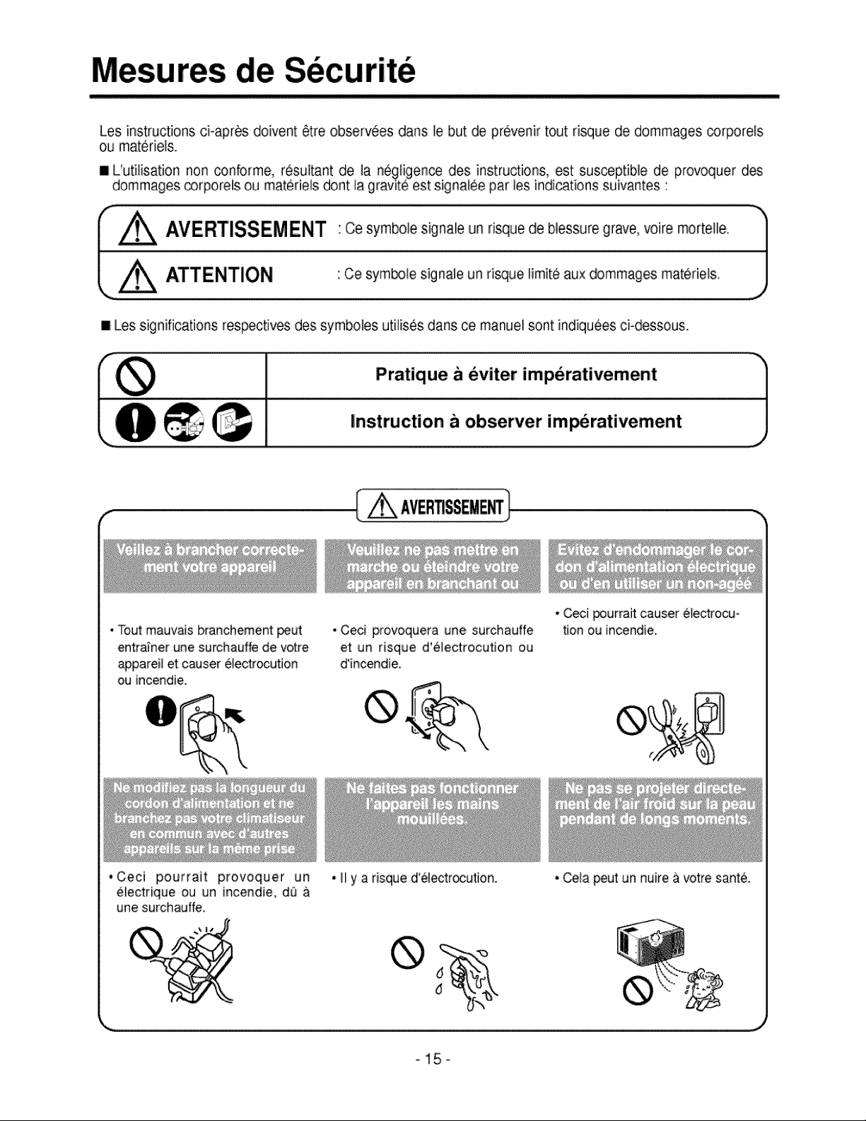
Les instructions ci-apres doivent 6tre observ6es dans le but de prevenir tout risque de dommages _rporels
ou materiels.
I L'utilisation non conforme, resultant de la negligence des instructions, est susceptible de provoquer des
dommages _rporels ou materiels dent la gravite est signalee par les indications suivantes :
_ A'_E'RTISS E rVIE NT " Ce symbOle sig hale un risque de blessure g_ave' MOire mOl'tel'e _%'1
L_ "Ce sym_le signale un ri_ue limit6 aux dommages materiels. ]
/
#
I Les significations respectives des symboles utilises dans ce manuel sont indiqu6es ci-dessous.
Pratique b eviter imperativement -"]
J
Instruction a observer imperativement
( _ AVER_SSEE_)
• Tout mauvais branchement peut
entrainer une surchauffe de votre
appareil et causer electrocution
ou incendie.
*Ceci pourrait provoquer un
•Ceci provoquera une surchauffe
et un risque d'electrocution ou
d'incendie_
. Ny a risqued'eledrc,cution,
. Ceci _urrait causer electrocu o
_on ou incendie,
electrique ou un incendie, dO &
une surchauffe.
• Cela peutun nuire & votre sante.
-15-
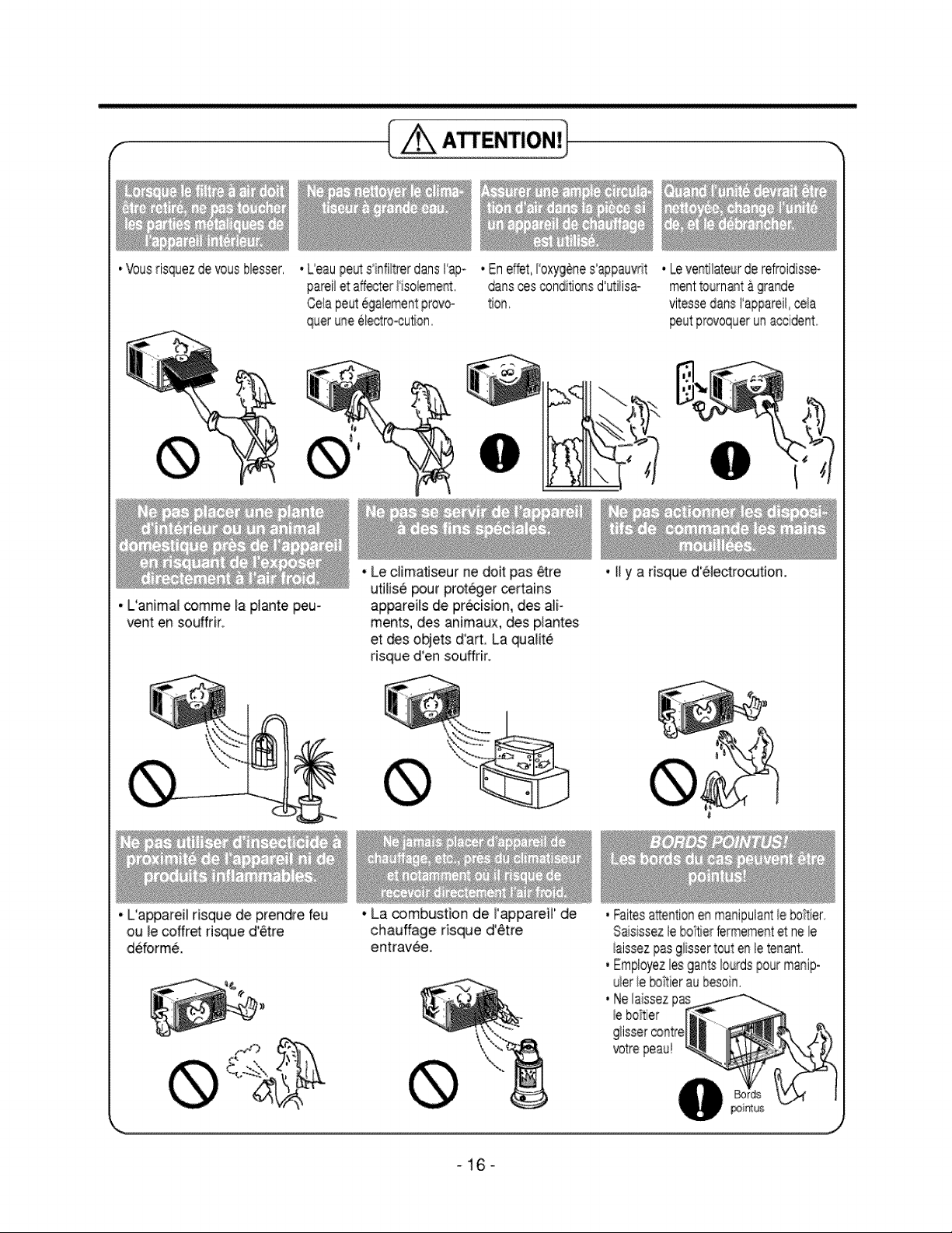
•Vousrisquezdevousblesser
[ o.,]
• Leaupe_ s'infiltrerdansI'apo
pareilet affe_der!1solement
Celiapeutegalementprovo-
queruneelectro-cution
• L'animaJcomme la pJantepeu-
vent en souffrir
•En effet, H'oxyg@nesappauvrit
darts ces conditionsd utiiisa-
tion
. LeventHateurderefroidisse-
menttournant&grande
peutprovoquerunaccident°
• Le ciimaflseur ne doitpas _tre
utiJise_ur proteger _rtains
appareils de pr_ision, des aUi-
merits, desanimaux, des plantes
etdeso_ets d'art. La qualit6
risqued'en souffrir.
• L'appareil risque de prendre feu
ou le coffret risque d'etre
deform&
• La _mbustion de _'appareH' de
chauffage risque d'etre
entravee,
• II ya risque d'electrocution.
,Faitesattentionenmanipulantleboitier
Sasissezlebof_erfermementet ne le
_aissezpasgiissertouten letenant
,Employezliesga_S_ourdspourmanip-
uierieboitieraubesoin.
• Neilaissez
_ebottler
g/issercontre
votrepeau!
_16o
FONCTIONNEMEN'[
• AVERTISSEMENT
Pour reduire le risque d'incendie, de choc electrique ou de blessures aux personnes, lisez les
IMPORTANTES INSTRUCTIONS DE SECURITE AVANT d'utiliser cet appareil.
• ATTENTION
Quand le conditionneur d'air a termine ses operations de refroidissement et qu'il est eteint ou place
en position ventilateur, attendez au moins 3 minutes avant de reinitialiser I'operation de refroidisse-
ment.
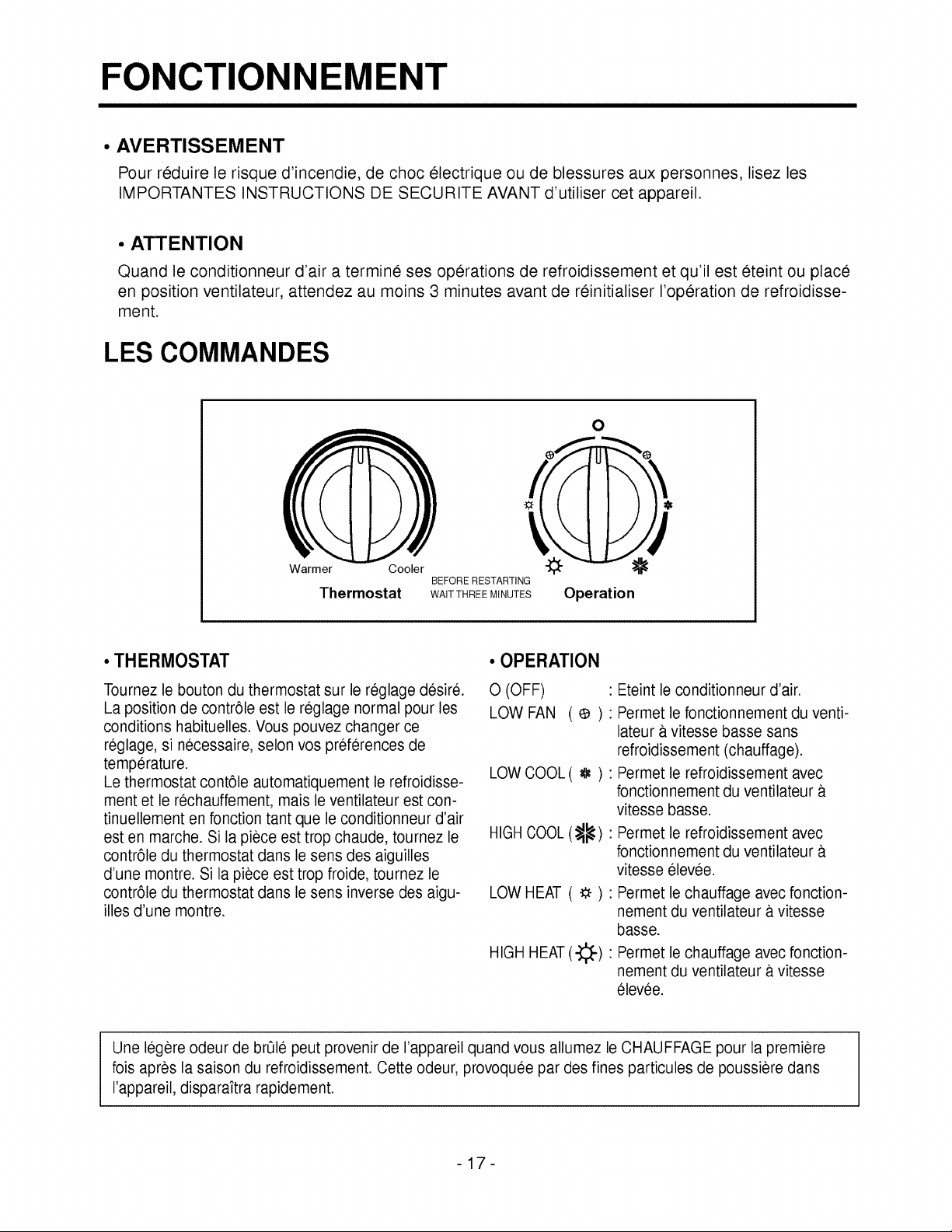
LES COMMANDES
Warmer Cooler
Thermostat
0
BEFORE RESTARTING
WAIT THREEMINUTES Operation
•THERMOSTAT
Tournez le bouton du thermostat sur le reglage desire.
La position de contrele est le reglage normal pour les
conditions habituelles. Vous pouvez changer ce
reglage, si necessaire, selon vos preferences de
temperature.
Le thermostat contele automatiquement le refroidisse-
ment et le rechauffement, mais le ventilateur est con-
tinuellement en fonction tant que le conditionneur d'air
est en marche. Si la piece est trop chaude, tournez le
contrele du thermostat dans le sens des aiguilles
d'une montre. Si la piece est trop froide, tournez le
contrele du thermostat dans le sens inverse des aigu-
illes d'une montre.
• OPERATION
0 (OFF)
LOW FAN (¢):
LOW COOL( _ ):
HIGHCOOL (_)"
LOW HEAT ( -_ ):
HIGHHEAT(-}::_-)"
: Eteint le conditionneur d'air.
Permet le fonctionnement du venti-
lateur 8,vitesse basse sans
refroidissement (chauffage).
Permet le refroidissement avec
fonctionnement du ventilateur a.
vitesse basse.
Permet le refroidissernent avec
fonctionnement du ventilateur a.
vitesse elevee.
Permet le chauffage avec fonction-
nement du ventilateur a.vitesse
basse.
Permet le chauffage avec fonction-
nement du ventilateur a.vitesse
6levee.
Une 16gereodeur de br01e peut provenir de I'appareil quand vous allumez le CHAUFFAGE pour la premiere
lois apres la saison du refroidissement. Oette odeur, provoquee par des fines particules de poussiere dans
rappareil, disparaitra rapidement.
-17-
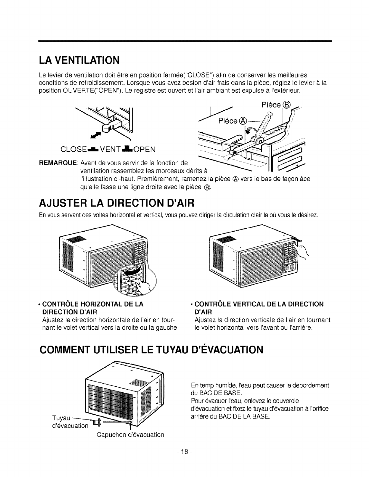
LA VENTILATION
Le levier de ventilation doit 6tre en position fermee("CLOSE") afin de conserver les meilleures
conditions de refroidissement. Lorsque vous avez besion d'air frais dans la piece, reglez le levier & la
position OUVERTE("OPEN"). Le registre est ouvert et Fair ambiant est expulse & I'exterieur.
Pi6ce
CLOSE_ VENT_OPEN
REMARQUE: Avant de vous servir de la fonction de
ventilation rassembiez les morceaux derits
Pfllustration ci=hauL Premierement, ramenez la piece ® vers Je bas de fawn ace
qu'elle fasse une tigne droite avec la piece @.
AJUSTER LA DIRECTION D'AIR
En vous servant des _ltes horizontal etvertical, vous pouvez diriger la circulation d'air la ou vous le desirez
• CONTROLE HORIZONTAL DE LA
DIRECTION D'AIR
Ajustez la direction horizontale de Fair en tour-
nant le volet vertical vers la droite ou la gauche
• CONTROLE VERTICAL DE LA DIRECTION
D'AIR
Ajustez la direction verticale de I'air en tournant
le volet horizontal vers I'avant ou l'arriere.
COMMENT UTILISER LE TUYAU D'EVACUATION
T_yau __
d evacuation _
Capuchon d'evacuation
En temp humide, Feaupeut _user le debordement
du BAC DE BASE.
Pour evacuer reau, enlevez le _uverde
d'evacuation et fixez le tuyau d'evacuation A I'orifioe
arriere du BAC DE LA BASE
-18°
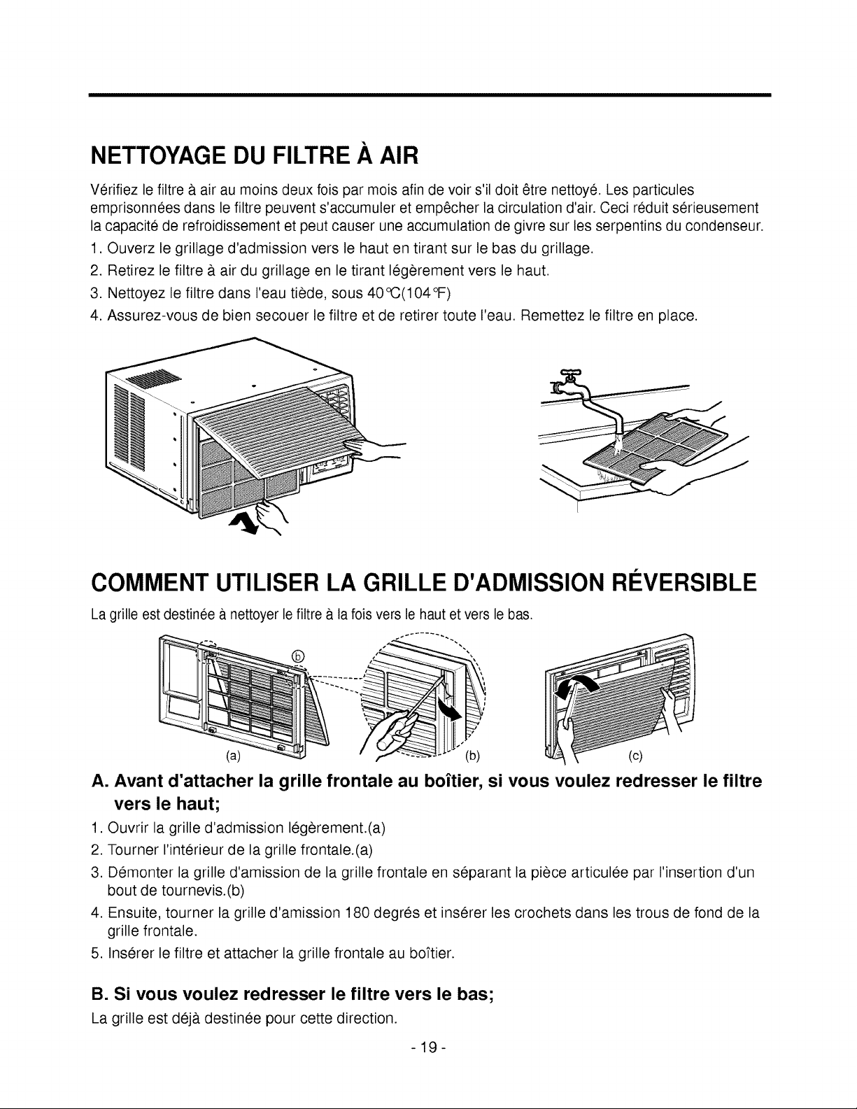
NETTOYAGE DU FILTRE A AIR
Verifiez le filtre & air au moins deux fois par mois afin de voir s'il dolt 6tre nettoye. Les particules
emprisonnees dans le filtre peuvent s'accumuler et emp6cher la circulation d'air. Ceci reduit serieusement
la capacite de refroidissement et peut causer une accumulation de givre sur les serpentins du condenseur.
1. Ouverz le grillage d'admission vers le haut en tirant sur le bas du grillage.
2. Retirez le filtre & air du grillage en le tirant legerement vers le haut.
3. Nettoyez le filtre dans I'eau tiede, sous 40°C(104°F)
4. Assurez-vous de bien secouer le filtre et de retirer toute I'eau. Remettez le filtre en place.
COMMENT UTILISER LA GRILLE D'ADMISSION REVERSIBLE
La grille est destinee a.nettoyer le filtre a la fois vers le haut etvers le bas.
®
(a) (b) (c)
A. Avant d'attacher la grille frontale au boitier, si vous voulez redresser le filtre
vers le haut;
1. Ouvrir la grille d'admission legerement.(a)
2. Tourner I'interieur de la grille frontale.(a)
3. Demonter la grille d'amission de la grille frontale en separant la piece articulee par I'insertion d'un
bout de tournevis.(b)
4. Ensuite, tourner la grille d'amission 180 degres et inserer les crochets dans les trous de fond de la
grille frontale.
5. Inserer le filtre et attacher la grille frontale au boftier.
B. Si vous voulez redresser le filtre vers le bas;
La grille est dej& destinee pour cette direction.
-19-
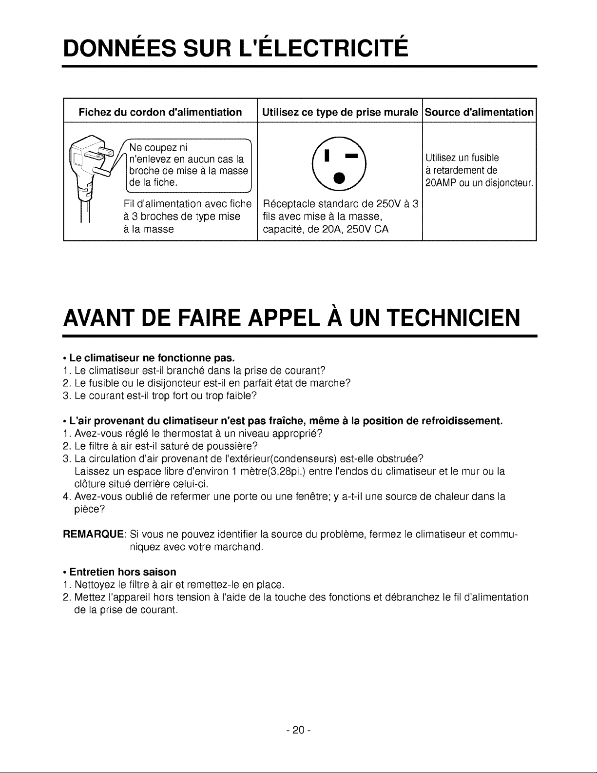
DONNEES SUR L'Et ECTRICITE
Fichez du cordon d'alimentiation
_-_, fNe coupez ni _'
_,f n'enlevez en aucun cas la
-- _ broche de mise a la masse
_ de la fiche. ._
Fil d'alimentation avec fiche
3 broches de type mise
la masse
Utilisez ce type de prise murale Source d'alimentation
Receptacle standard de 250V a. 3
ills avec mise & la masse,
capacite, de 20A, 250V CA
Utilisez un fusible
retardement de
20AMP ou un disjoncteur.
AVANT DE FAIRE APPEt A UN TECHNICIEN
• Le climatiseur ne fonctionne pas.
1. Le climatiseur est-il branche dans la prise de courant?
2. Le fusible ou le disijoncteur est-il en parfait etat de marche?
3. Le courant est-il trop fort ou trop faible?
° L'air provenant du climatiseur n'est pas fraiche, m_me a la position de refroidissement.
1. Avez-vous regle le thermostat & un niveau approprie?
2. Le filtre a. air est-il sature de poussiere?
3. La circulation d'air provenant de I'exterieur(condenseurs) est-elle obstruee?
Laissez un espace libre d'environ 1 metre(3.28pi.) entre I'endos du climatiseur et le mur ou la
cl6ture situe derriere celui-ci.
4. Avez-vous oublie de refermer une porte ou une fenetre; y a-t-il une source de chaleur dans la
piece?
REMARQUE: Si vous ne pouvez identifier la source du probleme, fermez le climatiseur et commu-
niquez avec votre marchand.
• Entretien hors saison
1. Nettoyez le filtre & air et remettez-le en place.
2. Mettez I'appareil hors tension & I'aide de la touche des fonctions et debranchez le fil d'alimentation
de la prise de courant.
- 20 -
IN
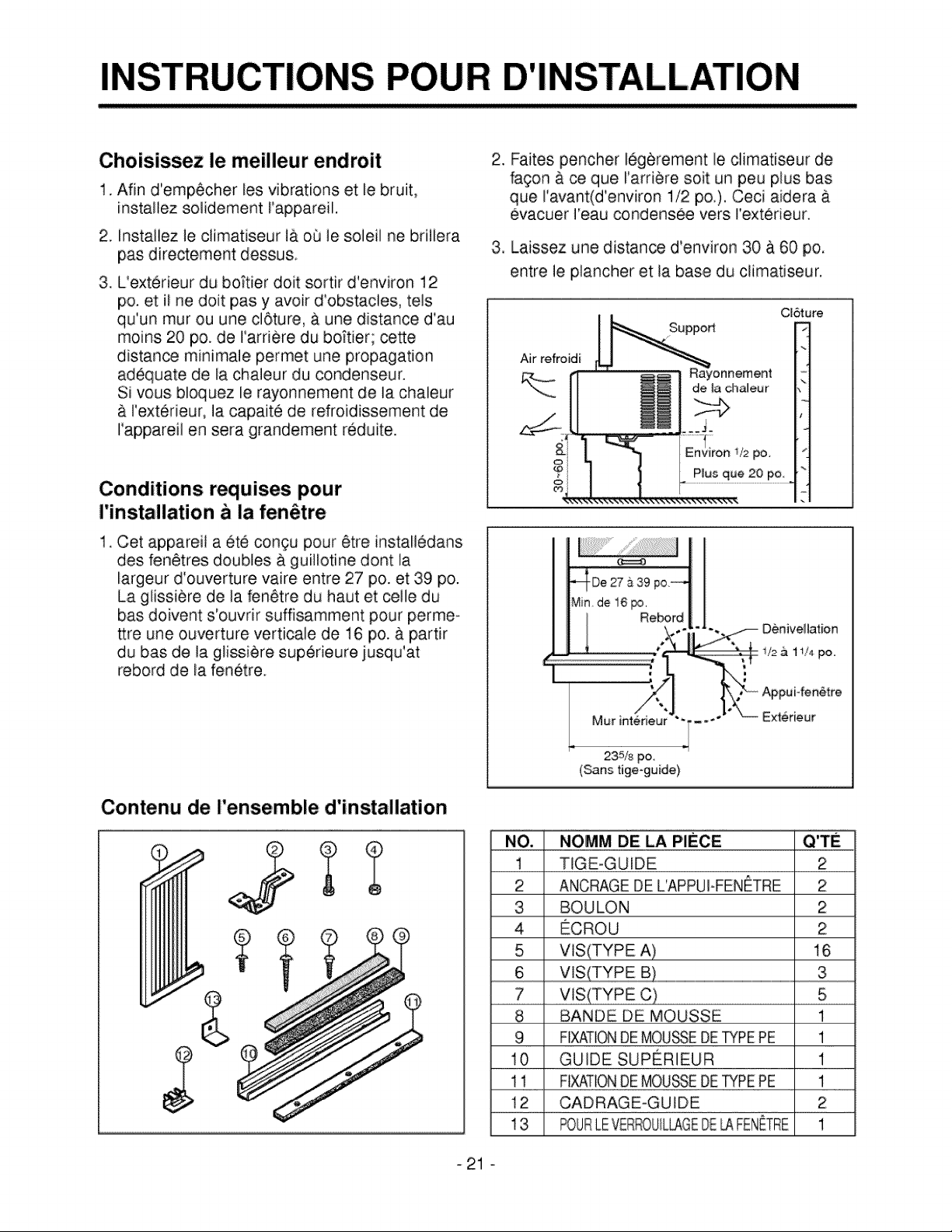
Choisissez le meilleur endroit
1. Afin d'emp6cher les vibrations et le bruit,
installez solidement rappareil.
2, ins,tallez leclimatiseur i& oQ le soleil nebriiiera
pas directement dessu&
3 L'exterieur du bokier doit sortir d'environ 12
po. et il ne doit pas y avoir d'obstacles, teis
qu'un tour ou une cl6ture, & une distance d'au
moins 20 po. de I'ardere du bo_tier; cette
distance minimale permet une propagation
adequate de la chaleur du condenseur.
Si vous. bloquez ie rayonnement de la chaleur
& I'exterieur, la capaite de refroidissement de
I'appareil en sera grandement reduite.
Conditions requises pour
I'installation b la fen_trie
1. Cet appareii a ete congu pour 6tre install6dans
des fen_tres doubles a guillotine dont la
largeur d'ouverture vaire entre 27 po. et 39 po.
La glissiere de la fen6tre du haut et celle du
bas doivent s'ouvrir suffisamment pour perme-
ttre une ouverture verticale de 16 po. & partir
du bas de la glissi_re sup6rieure iusqu'at
rebord de la fenetre.
Contenu de rensemble d'installation
2. Faites pencher legerement le climatiseur de
fagon a ca que I'ardere soit un peu plus bas
que I'avant(d'environ 1/2 po.). Ceci aidera
evacuer reau condensee vers rexterieur.
3, Laissez une distan_ d'environ 30 a 60 po,
entre le plancher et la base du climatiseur.
CL6ture
Air refroidi
Rayonnement
de _a chaJeur
_/2po
Pgusque 20 po
Denivellation
v2 & 1I14po=
Appui-fen6tre
Mur intedeur Exterieur
235/8 po
(Sans tige-guide)
NO., NOMM DE LA PIECE
1 TIGE-GUIDE 2
2 ANCRAGE DEL'APPUFFENETRE 2
3 BOULON 2
4 ECROU 2:
5 VlS(TYPE A) 16
6 VlS ..........................................................................................................................................................................................3
7 VIS(TYPE C) 5
8 BANDE DE MOUSSE 1
9 FIXATIONDE MOU_E DE_PE PE 1
10 GUIDE SUPERIIEUR 1
11 FIXATIONDE MOUSE DETYPEPE 1
12 CADRAGE-GUIDE 2
13 FOURLEVER_DUILLAGEDE_ FENETRE 1
_21 °
OUTILS SUGGERES
I Tournevis(+,-), regle, couteau, marteau, crayon et niveau b bulle d'air [
L I
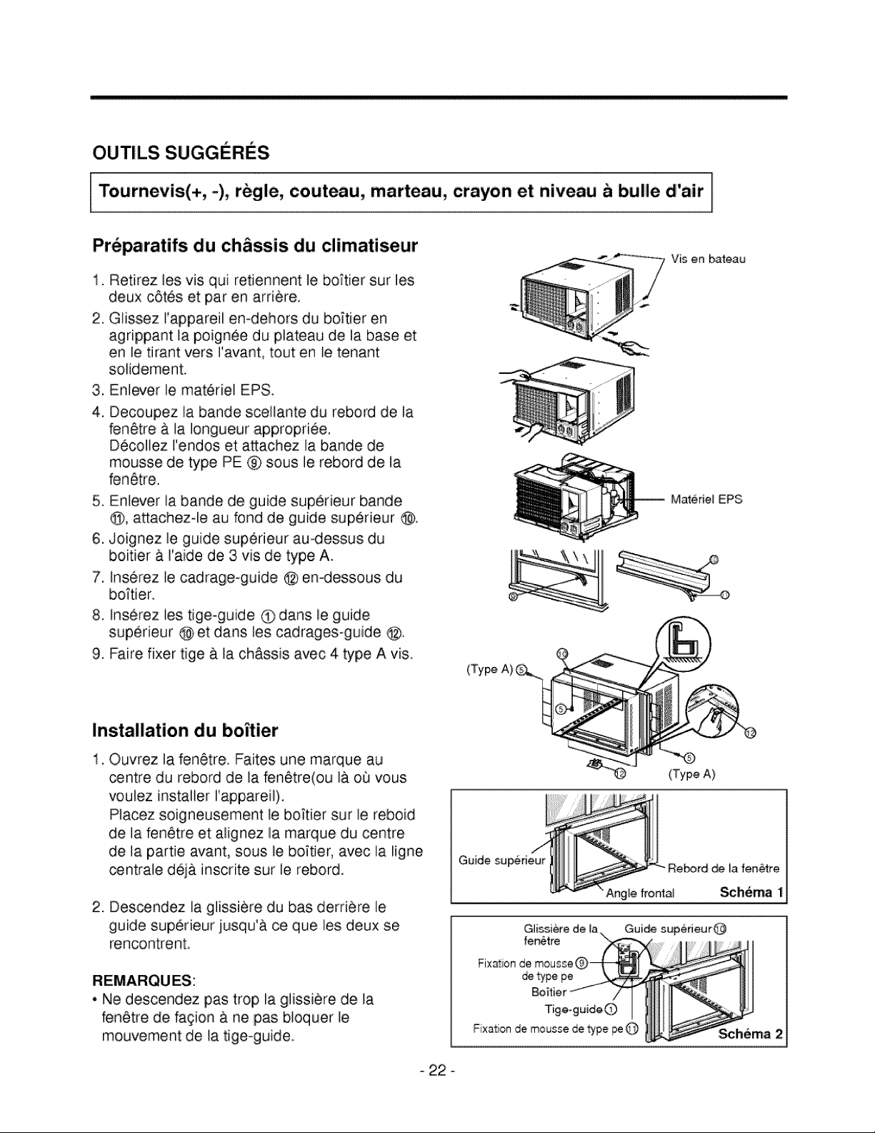
Preparatifs du ch&ssis du climatiseur
1. Retirez les vis qui retiennent le bottler sur les
deux c6tes et par en arriere.
2. Glissez I'appareil en-dehors du boitier en
agrippant la poignee du plateau de la base et
en le tirant vers I'avant, tout en le tenant
solidement.
3. Enlever le materiel EPS.
4. Decoupez la bande scellante du rebord de la
fenetre a. la Iongueur appropriee.
Decollez l'endos et attachez la bande de
mousse de type PE @ sous le rebord de la
fenetre.
5. Enlever la bande de guide superieur bande
@, attachezqe au fond de guide superieur @.
6. Joignez le guide supedeur au-dessus du
boitier & raide de 3 vis de type A.
7, Inse,rez le cadrage-guide @ enodessous du
boTtien
8. Inserez ies tige-guide O dans le guide
superieur @ et dans les cadrages-guide @.
9. Faire fixer tige & la ch&ssis avec 4 type A vis.
Installation du boitier
1. Ouvrez la fenetre. Faites une marque au
_ntre du rebord de la fenetre(ou la o0 vous
voulez installer I'appareil).
Placez soigneusement le boftier sur le reboid
de la fenetre et: alignez la marque du centre
de la pattie avant, sous le boftier, avec la Iigne
centrale deja inscrite sur le rebord.
2. Des_ndez la glissiere du bas derriere le
guide supedeur jusqu'& ce que les deux se
rencontrent
• Ne descendez pas trop la glissiere de la
fenetre de fagion a ne pas bloquer le
mouvement de la tige-guide.
Vis en bateau
Materiel EPS
(TypeA)
Guide supedeur
Re_rd _ la fen6tre
Angle, fror_lal Schema 1
Gl{ssiere de la Guide su
- 22 °
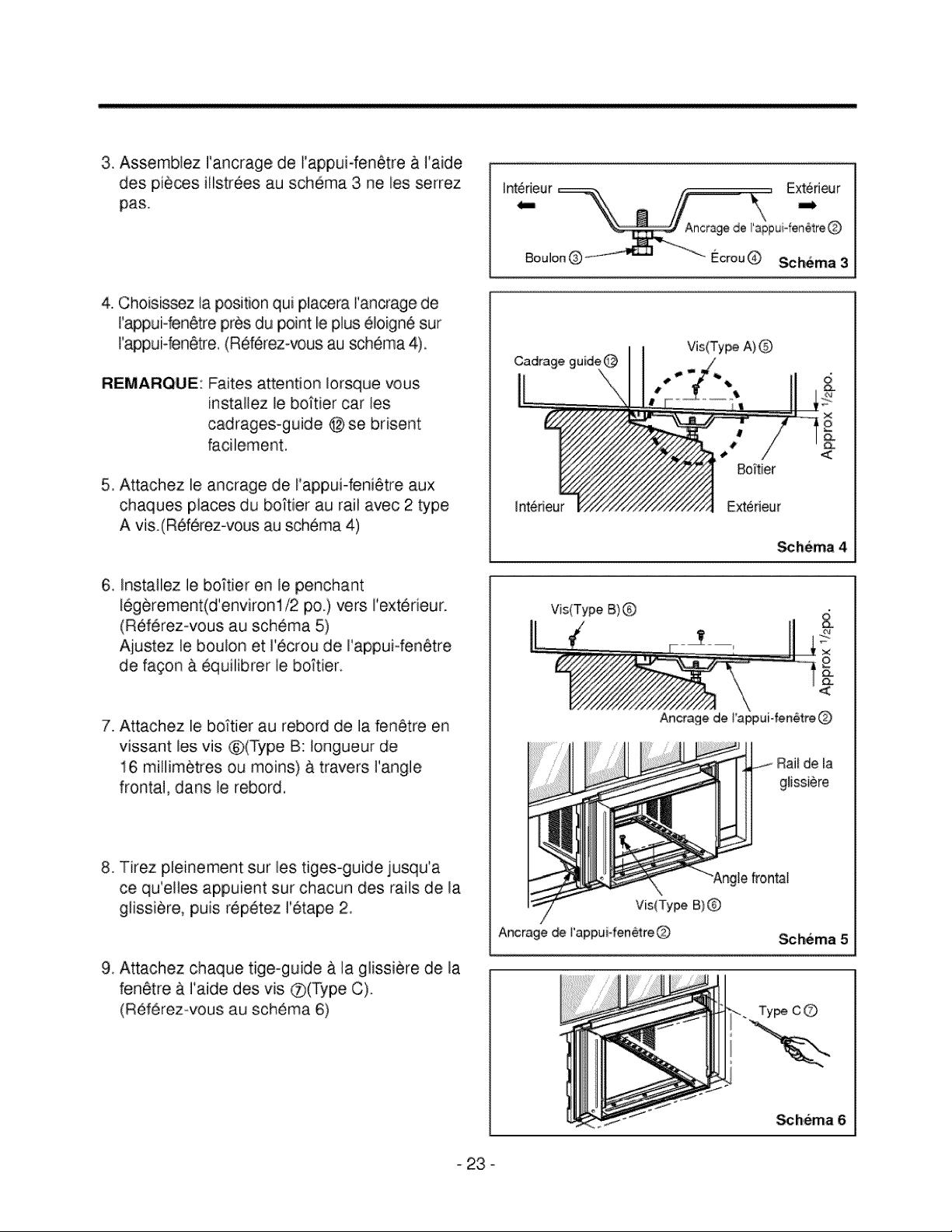
3 Assemblez I'ancrage de I'appuiofen0tre & I'aide
des pieces illstrees au schema 3 ne les serrez
pas.
4. Choisissez la position qui placera rancrage de
rappui-fen0tre pros du point le plus 01oign6 sur
I'appuHen0tre, (Ref6rezwous au schema 4).
REMARQUE: Faites attention Iorsque vous
instaflez le boTtier car les
cadrages-guide @ se brisent
facilement.
5. Attachez le ancrage de I'appui-feni0tre aux
chaques places du boi_tier au rail avec 2 type
A vis.(Referez-vous au schema 4)
6. Installez le boftier en le penchant
legerement(d'environli2 po.) vers I'exterieur.
(Ref0rez-vous au schema 5)
Aiustez le boulon et 1'ecrou de Fappui°fen0tre
de fagon & equilibrer le bottler.
7. Attachez le boi"tier au rebord de la fen0tre en
vissant les vis @(Type B: Iongueur de
16 miflim0tres ou moins) & travers I'angle
frontal, dans le rebord,
8. Tirez pleinement sur les tiges-guide jusqu'a
ce qu'elles appuient sur chacun des rails de la
glissiere, puis repetez I'etape 2.
9, Attachez chaque tige-guide & la glissi_re de la
fen0tre & I'aide des vis Q(Type C).
(Referez-vous au schema 6)
Vis(Type A) 0
Interieur Ext:erieur
<
_hema 4
Vis(Type B)
\
Ancrage de I'appui-fen_tre Q
Rail de la
giissiCre
"Angle_ontal
Vis(Type B)
Ancrage de I'appui-fen_re _ _hema 5
_hema 6
- 23 °
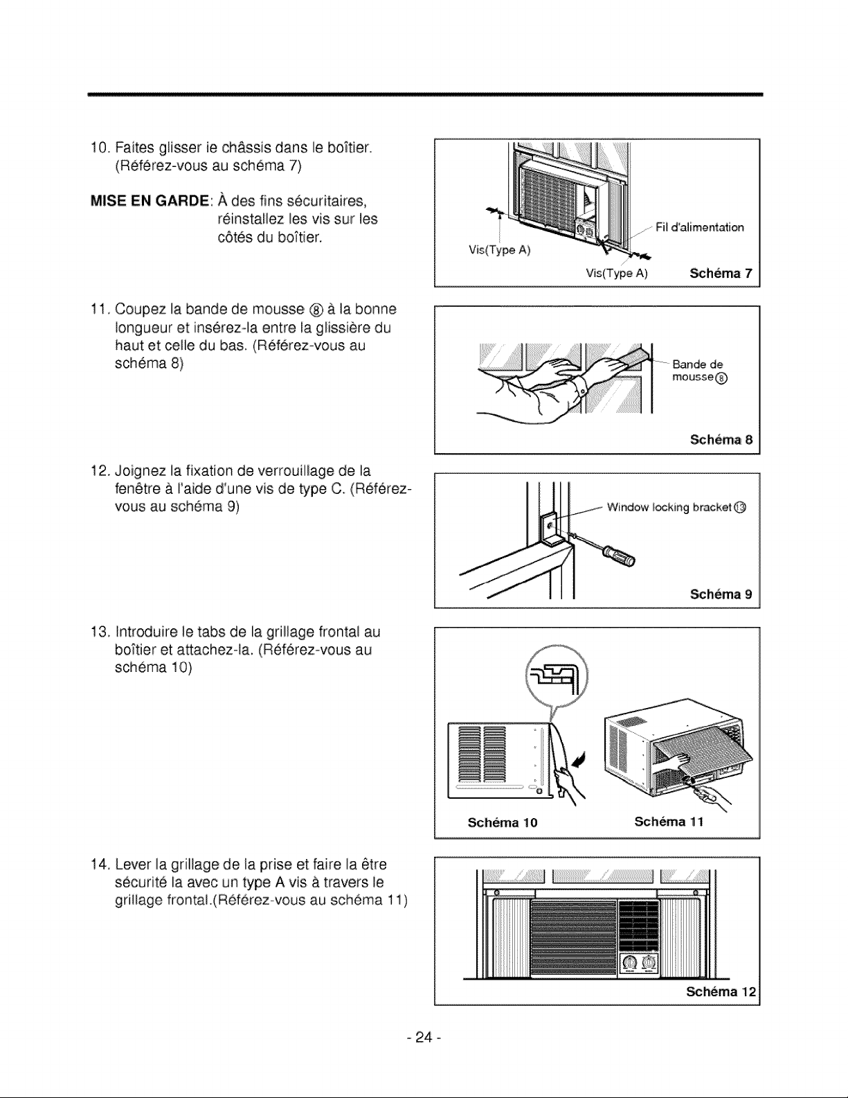
10.Faitesgiisserie ch&ssisdansle boftier.
(Referez-vousau schema7)
MISE EN GARDE: A des fins securitaires,
reinstallez les vis sur les
cetes du bo;tier.
11. Coupez la bande de mousse ® & la bonne
longueur et inserezola entre la glissiere du
haut et celle du bas. (Referez-vous au
schema 8)
12. Joignez la fixation de verrouillage de la
feinetre a I'aide d'une vis de type C+ (Referezo
vous au schema 9)
Vis(Type A)
....Fil d'alimentation
Vis(Type A) _hema 7
Schema 8
Schema 9
13, Introduire le tabs de la grillage frontal au
boJtier et attachez-la, (Referez-vous au
schema 10)
Schema 11
14, Lever la grillage de la prise et faire la #tre
securite la avec un type A vis a travers le
grillage frontal.(Referez-vous au schema 11)
!!i!!!i!7!!i!!!i!7!!i!!!i!7!!i!!!i!7
_hema 12
- 24 °

MESURES DE SECURITE ELECTRIQUES
• MESURES DE SECURITE _'LECTRIQUES
IINSTRUCTIONS IMPORTANTES RELATIVES A LA
MISE A LA TERRE
Le fild'alimentation de ce climatiseur est muni d'une
fiche de mise & la terre & trois broches. Brancheq
cette fiche dans une prise a trois trois ouvertures
standard afin de reduire les risques de choc electrique
ou d'incendie.
FUSIBLE - Veuillez utiliser un fusible a retardement
ou un disjoncteur. Referezvous a la
plaque du numero de serie pour conna/tre
les exigences de tension.
APPAREILS DE 230 et 208 VOLTS
Le fil d'alimentation de cet appareil est muni d'une
fiche de mise a la terre a trois broches. Branchez
cette fiche dans une prise a trois ouvertures standard
(voir le schema ci-dessous) afin de reduire les
risques de choc electrique ou d'incendie.
Si vous ne possedez pas de telle prise, vous devez en
faire installer une par un electricien, selon les normes
du Code National de I' Electricite et les reglements de
la compagnie d'electricite locale.
REMARQUE: N'UTILISEZ PAS DECORDON D'EX-
TENSION.
- 25 -
rABLA DE
CARACTER[ST]CAS 26
PRECAUCIONES IM PORTANTES DE SEG U RIDAD .................................................................... 27
FUNCIONAMIENTO .................................................................................................................... 29
FU NC]O NAMI ENTO ....................................................................................................................... 29
VENTILACt0N .............................................................................................................................. 30
PARA CONTROLAR LA DIRECCION DEL AIRE .......................................................................... 30
COMO INSTALAR EL TUBO DE DESAAGOE ..................................................................................... 30
MMPIEZA DE FIWRO DE AIRE .................................................................................................... 31
COMO USAR LA REJ]LLA DE ENTRADA REVERSIBLE .......................................................... 31
INFORMACJ0N ELECTRICA .............................................................................................................. 32
ANTES DE LLAMAR POR SERVlC]O .............................................................................................. 32
INSTRUCClONES DE INSTALAClON .............................................................................................. 33
SEGUR IDAD ELECTR ICA ............................................................................................................... 37
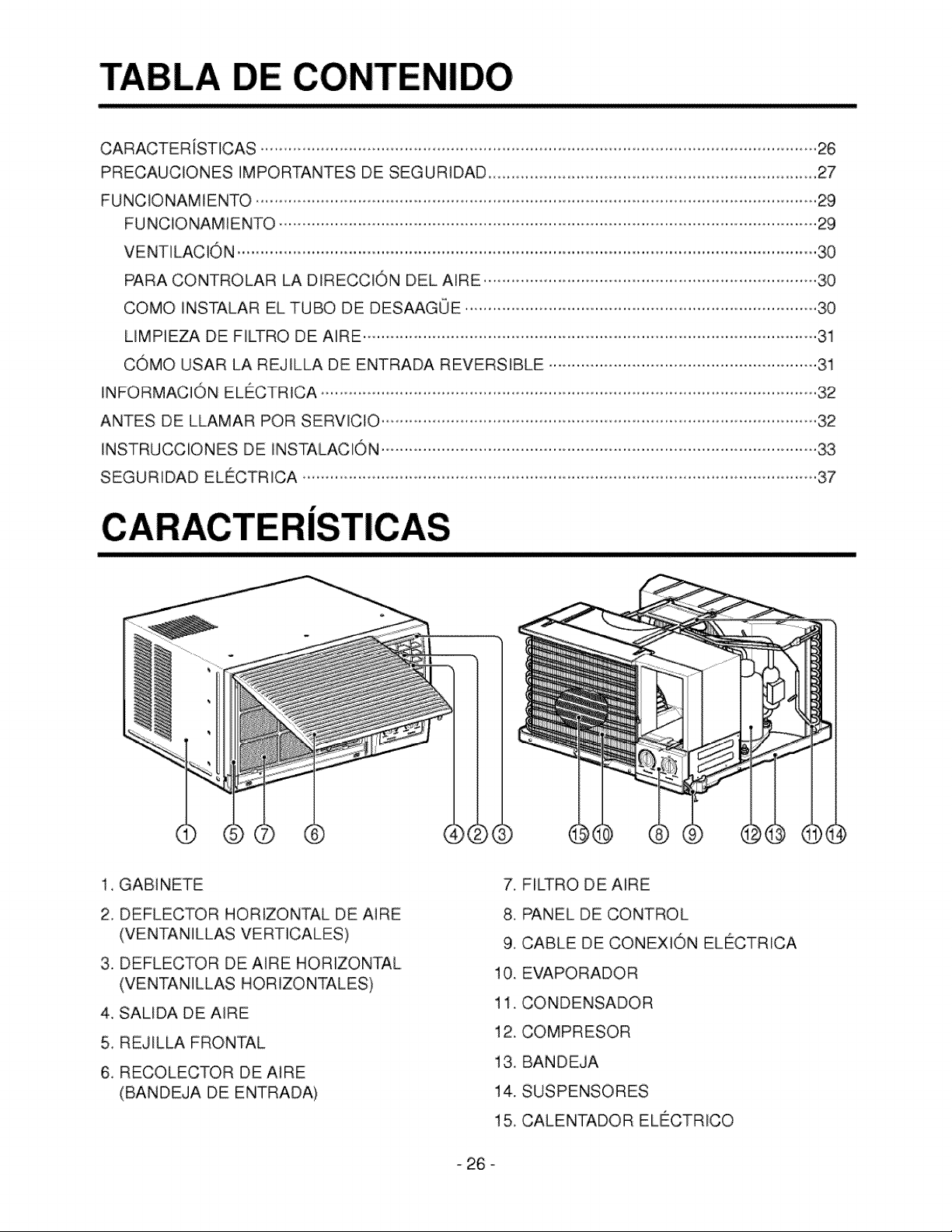
1, GAB]NETE
2, DEFLECTOR HORIZONTAL DE AJRE
(VENTAN]LLAS VERTICALES)
3, DEFLECTOR DE AIRE HORIZONTAL
(VENTAN]LLAS HOR IZONTALES)
4, SALIDA DE AIRE
5, REJILLA FRONTAL
6, RECOLECTOR DE A]RE
(BANDEJA DE ENTRADA)
7, FILTRO DE AIRE
8, PANEL DE CONTROL
9, CABLE DE CONEXlON ELECTRICA
10. EVAPORADOR
11. CONDENSADOR
12. COMPRESOR
13. BANDEJA
14. SUSPENSORES
15, CALENTADOR ELECTRICO
26 o
iones
Paraprevenirtanto lesionesai usuario u otras personascomodaSos materiales,es preciso seguir estas inslTucciones.
mEl manejoincorrectodebido a la inobservanciade estasins_ruccionespu_e causar lesioneso da_oscuya grav_ad
esta clasificadaen Jassiguientes indicaciones.
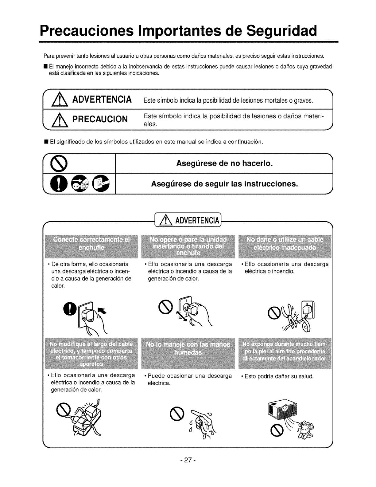
r_ z_ ADVERTENCIA Es_e sirnbolo indioa I_ posibilidad de lesiones mor_les o g[av_.
t± a,osEstes,mbo,o,od,oa,a0os,b,,,0ad0e,es,ooeso0a0osma er,JJ
m El significado de _oss/mbolos utiliza_s en este manual se indica a continuaci6n.
Asegurese de no hacerio.
Asegorese de seguir las instrucciones.
• De otra forma,ello ocasionada
una descarga electdca o inceno
dio a causa de la generaci6n
_ton
• E_lo ocasionarfa una descarga
electrica o incendio a causa de la
generaci6n de talon
•Ello ocasionaria una descarga
el6ctrica o incendio.
• EHoocasionaria una descarga
el_ctrica o incendio a causa de la
generaci6n de calon
•pueide ocasionar una descarga
electrica.
•Esto podrla daSar susalud.
27 o
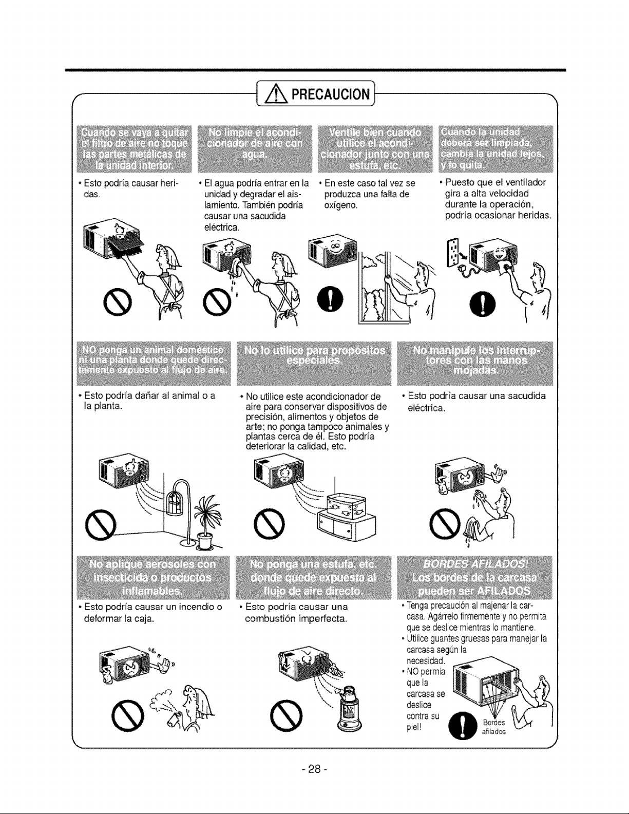
• Estopodriacau_r heri
das
PRECAUCION
• E_aguapodr[a entraren la
unidady degradare_ais-
lamiento.Tambi6npodria
_usar una sacudida
el_trica,
• Es_o_dria daSar a_animal o a
la p_ant&
• Esto _dria causar un incendio o
deformar Jacaja.
• Enesle_so t:aJvez se
produzca unafai_ade
oxigeno,
• Puesto que e_ventilador
gira a altavemocidad
durante ia o_racidn,
_drla ocasionar hedda&
• No utilice este acondicionador de
aire paraconservardispositivos de
precisiSn,alimentosyo_etos de
arte; no ponga tamp_o animates y
p_antascerca de eL Esto podrfa
deteriorar_aca_idad,etc.
• Esto podria causar una
combustidn imperfect&
• Esto p_dria causar una sacudida
electric&
Tengaprecauci6na/maienarIs car°
casa Ag_rm/ofirmementey nopermits
quese deslicemientmsIomantiene
U_liceguantesgruesasparamanejarIs
carcasasegQnla
secesidad,
NOpermia
quela
carcs_ss,se
desHce
contra su
pie1!
- 28 °
FUNCIONAMIENTO
•ADVERTENCIA
Para reducir el riesgo de incendios, sacudidas electricas o da_os alas personas, lea las INSTRUC-
CLONES DE SEGURIDAD IMPORTANTES antes de utilizar este dispositivo.
• ATENCION
Cuando el aire acondicionado ha efectuado su funcion de enfriamiento y se apaga o puesto en funcion
ventilador, espere por Io menos 3 minutos antes de restablecer la funci6n de enfriamiento de nuevo.
FUNCIONAMIENTO
Warmer Cooler
Thermostat
O
BEFORE RESTARTING
WAIT THREE MINUTES Operation
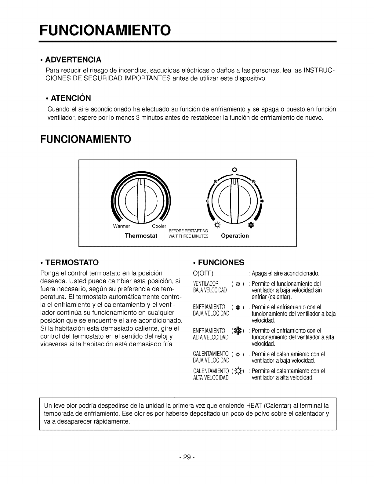
• TERMOSTATO
Ponga el control termostato en la posicion
deseada. Usted puede cambiar esta posicion, si
fuera necesario, segOn su preferencia de tem-
peratura. El termostato automa.ticamente contro-
la el enfriamiento y el calentamiento y el venti-
lador continOa su funcionamiento en cualquier
posicion que se encuentre el aire acondicionado.
Si la habitacion esta. demasiado caliente, gire el
control del termostato en el sentido del reloj y
viceversa si la habitaci6n esta. demasiado frfa.
• FUNCIONES
O(OFF)
VENTILADOR ¢ )
BAJAVELOCIDAD
ENFRIAMIENTO_ )
BAJAVELOCIDAD
ENFRIAMIENTO(:_)
ALTAVELOCIDAD
CALENTAMIENTO(_)
BAJAVELOCIDAD
CALENTAMIENTO(-_-)
ALTAVELOCIDAD
Apagael aireacondicionado.
Permiteel funcionamientodel
ventiladora baja velocidadsin
enfriar (calentar).
Permiteel enfriamientocon el
funcionamientodel ventiladora baja
velocidad.
: Permiteel enfriamientocon el
funcionamientodel ventiladora alia
velocidad.
: Permiteel calentamientoconel
ventiladora baja velocidad.
: Permiteel calentamientoconel
ventiladora alia velocidad.
Un leve olor podria despedirse de la unidad la primera vez que enciende HEAT (Calentar) al terminal la
temporada de enfriamiento. Ese olor es por haberse depositado un poco de polvo sobre el calentador y
va a desaparecer rapidamente.
- 29 -
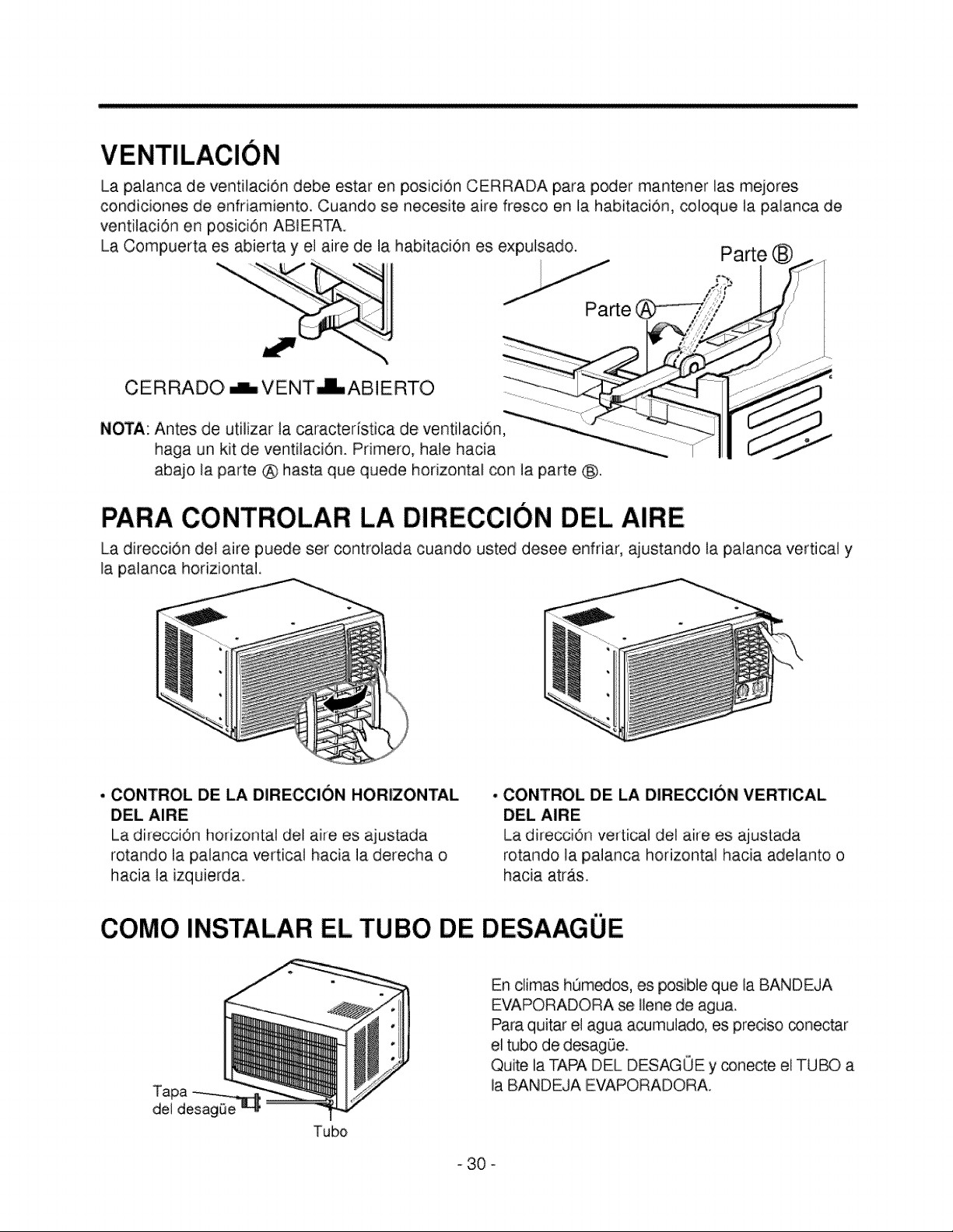
Lapalancade ventilaciondebeestaren posici6nCERRADAparapodermantenerlas mejores
condicionesde enfriamiento.Cuandose necesJteairefrescoen la habitaci6n,coloquela paiancade
ventilaci6nen posbi6nABIERTA.
LaCompuertaesabiertay el airede la habitaci6nes expulsado. Parte ®
Parte
CERRADO _VENT_ABIERTO
NOTA: Antes de utflizar ta caracteristica de ventilaci6n
haga un kit de ventilaci6n. Primero, hale hacia
abajo la parte @ hasta que quede horizontal con la parte _.
PARA CONTROLAR LA DiRECCION DEL AIRE
La direcci6n del aire puede ser controlada cuando usted desee enfriar, ajustando la palanca vertical y
la palanca horiziontah
, CONTROL DE LA DIRECCION HORIZONTAL
OEL AIRE
La direcciOn horizontal del aire es ajustada
rotando la palanca vertical hacia la derecha o
hacia la izquierda.
. CONTROL DE LA DIRECCION VERTICAL
DEL AIRE
La direcci0n vertical del aire es ajustada
rotando la paianca horizontal hacia adelanto o
hacia atras.
COMO iNSTALAR EL TUBO DE DESAAGUE
Tubo
En climas hOm_os, es posible que la BANDEJA
EVAPORADORA se Ilene de agua.
Para quitar el agua acumulado, es preciso conectar
el tubo de desagOe.
Quite la TARA DEL DESAGOE yconecte el TUBO a
la BANDEJA EVAPORADORA.
30 o
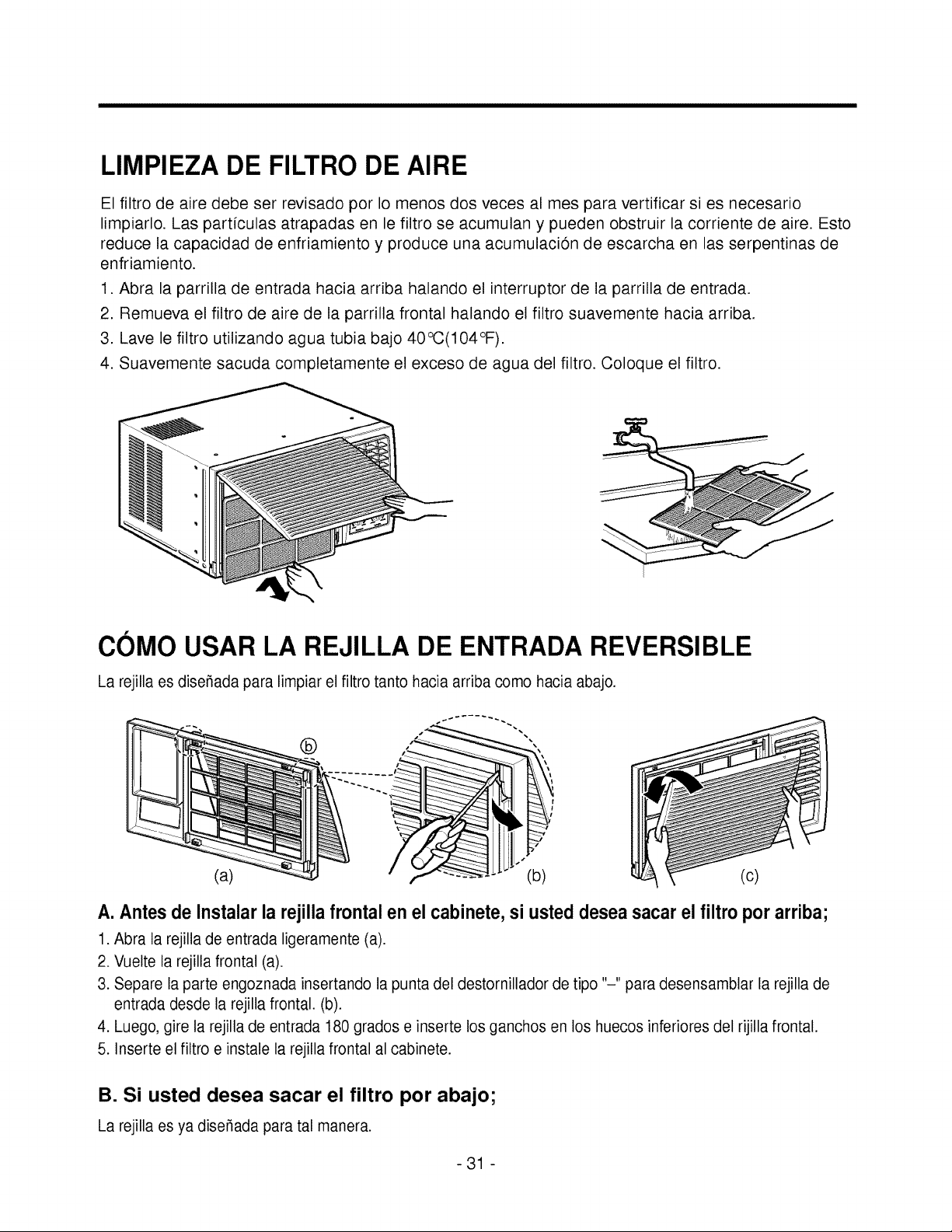
LIMPIEZA DE FILTRODE AIRE
El filtro de aire debe ser revisado por Io menos dos veces al mes para vertificar si es necesario
limpiarlo. Las partfculas atrapadas en le filtro se acumulan y pueden obstruir la corriente de aire. Esto
reduce la capacidad de enfriamiento y produce una acumulaci6n de escarcha en las serpentinas de
enfriamiento.
1. Abra la parrilla de entrada hacia arriba halando el interruptor de la parrilla de entrada.
2. Remueva el filtro de aire de la parrilla frontal halando el filtro suavemente hacia arriba.
3. Lave le filtro utilizando agua tubia bajo 40°C(104°F).
4. Suavemente sacuda completamente el exceso de agua del filtro. Coloque el filtro.
COMO USAR LA REJILLA DE ENTRADA REVERSIBLE
La rejilla es dise_ada para limpiar el filtro tanto hacia arriba como hacia abajo.
®
(c)
(a) 2 (b)
A.Antes deInstalarla rejilla frontal en el cabinete, si usted deseasacarelfiltro porarriba;
1.Abra la rejilla de entrada ligeramente (a).
2. Vuelte la rejilla frontal (a).
3. Separe la parte engoznada insertando la punta del destornillador de tipo "-" para desensamblar la rejilla de
entrada desde la rejilla frontal. (b).
4. Luego, gire la rejilla de entrada 180 grados e inserte losganchos en los huecos inferiores del rijilla frontal.
5. Inserte el filtro e instale la rejilla frontal al cabinete.
B. Si usted desea sacar el filtro por abajo;
La rejilla es ya dise_ada para tal manera.
-31 -
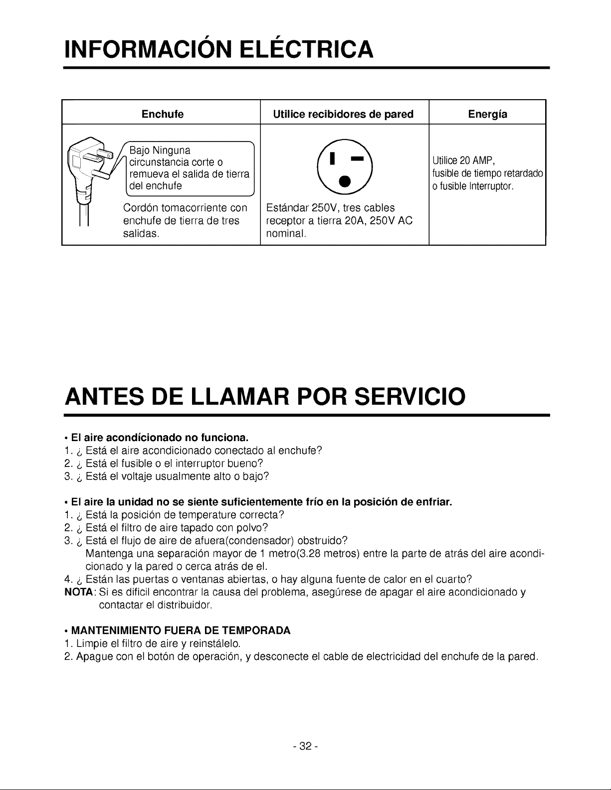
INFORMACION El. ECTRICA
Enchufe Utilice recibidores de pared Energia
_.-, fBajo Ninguna
_Jy circunstancia corte
0
_remueva el salida de tierra
del enchufe
CordOn tomacorriente con
enchufe de tierra de tres
salidas.
Esta.ndar 250V, tres cables
receptor a tierra 20A, 250V AC
nominal.
Utilice 20 AMP,
fusible de tiempo retardado
o fusible Interruptor.
ANTES DE LLAMAR POR SERVICIO
, El aire acondicionado no funciona.
1. _ Esta. el aire acondicionado conectado al enchufe?
2. _ Esta el fusible o el interruptor bueno?
3. _, Est,. el voltaje usualmente alto o bajo?
° El aire la unidad no se siente suficientemente frio en la posicion de enfriar.
1. _ Esta. la posiciOn de temperature correcta?
2. _, Esta. el filtro de aire tapado con polvo?
3. _, Esta. el flujo de aire de afuera(condensador) obstruido?
Mantenga una separacion mayor de 1 metro(3.28 metros) entre la parte de atras del aire acondi-
cionado y la pared o cerca atra.s de el.
4. _ Estan las puertas o ventanas abiertas, o hay alguna fuente de calor en el cuarto?
NOTA: Si es dificil encontrar la causa del problema, asegOrese de apagar el aire acondicionado y
contactar el distribuidor.
• MANTENIMIENTO FUERA DE TEMPORADA
1. Limpie el filtro de aire y reinstalelo.
2. Apague con el boton de operacion, y desconecte el cable de electricidad del enchufe de la pared.
- 32 -
IN I
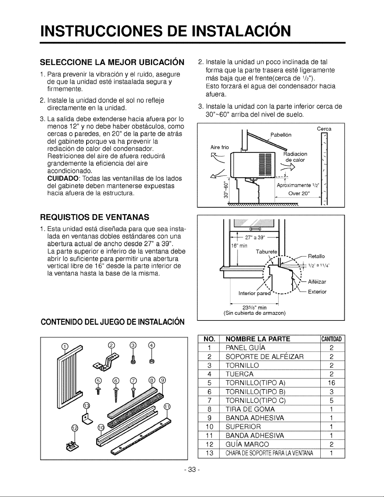
SELECCiONE LA MEJOR UBICACION
1. Para prevenir la vibraci0n y el ruido, asegure
de que la unidad este instaalada segura y
firmemente.
2. Instale taunidad donde elsol norefleje
directamente en la unidad.
3. La salida debe extenderse hacia afuera por Io
menos 12" y no debe haber obstaculos, como
cercas o paredes, en 20" de la parte de atras
del gabinete porque va ha prevenir la
rediaci6n de calor del condensador,
Restriciones del aire de afuera reducira
grandemente la eficiencia del aire
a@ndicionado.
CUIDADO: Todas las ventanillas de los lados
del gabinete deben mantenerse expuestas
hacia afuera de la estructura.
REQUlSTIOS DE VENTANAS
1. Esta unidad esta disefiada para que sea insta-
lada en ventanas dobles estAndares con una
abertura actual de ancho desde 27" a 39".
La parte superior e inferiro de la ventana debe
abnr Io suficiente para permitir una abertura
,vertical libre de 16" desde la parte inferior de
la ventana hasta la base de la misma.
CONITENIDODEL JUEGO DEINSTALACION
2_
.
Instale ia unidad un poco inclinada de tal
forma que la parte trasera est6 ligeramente
mrs baja que el frente(cerca de 1/2").
Esto forzara el agua del condensador hacia
afuera.
Instale la unidad con la parte inferior cerca de
30"~60" arriba del nivel de suelo.
Cerca
I eH6n
Aire frio
_,_ r] _M | Radiacion
Interior pare€
235/8" rain
(Sin cubierta de arm_on)
C_NO,
1
2
3
4
5
6
7
8
9
10
11
12
13
NOMBRE LA PARTE
PANEL GUiA
SOPORTE DE ALFEIZAR
TORNILLO
TUERCA
TOR N ILLO(TIPO A)
TORNILLO
TORN ILLO(TIPO C)
TiRA DE GOMA
BANDA ADH ESlVA
SUPERIOR
BANDA ADH ESWA
GUiA MARCO
CHRPADE_OPORTEPARRLAVB'_ffRNA
2
2
2
2
16
3
5
1
1
1
1
2
1
33 o
HERRAMIENTAS REQU ERIDAS SUGERIDAS
REGLA, CUCJILLO, MARTILLO, LAPIZ NIVEL
DEST_ORNILLADOR(+,
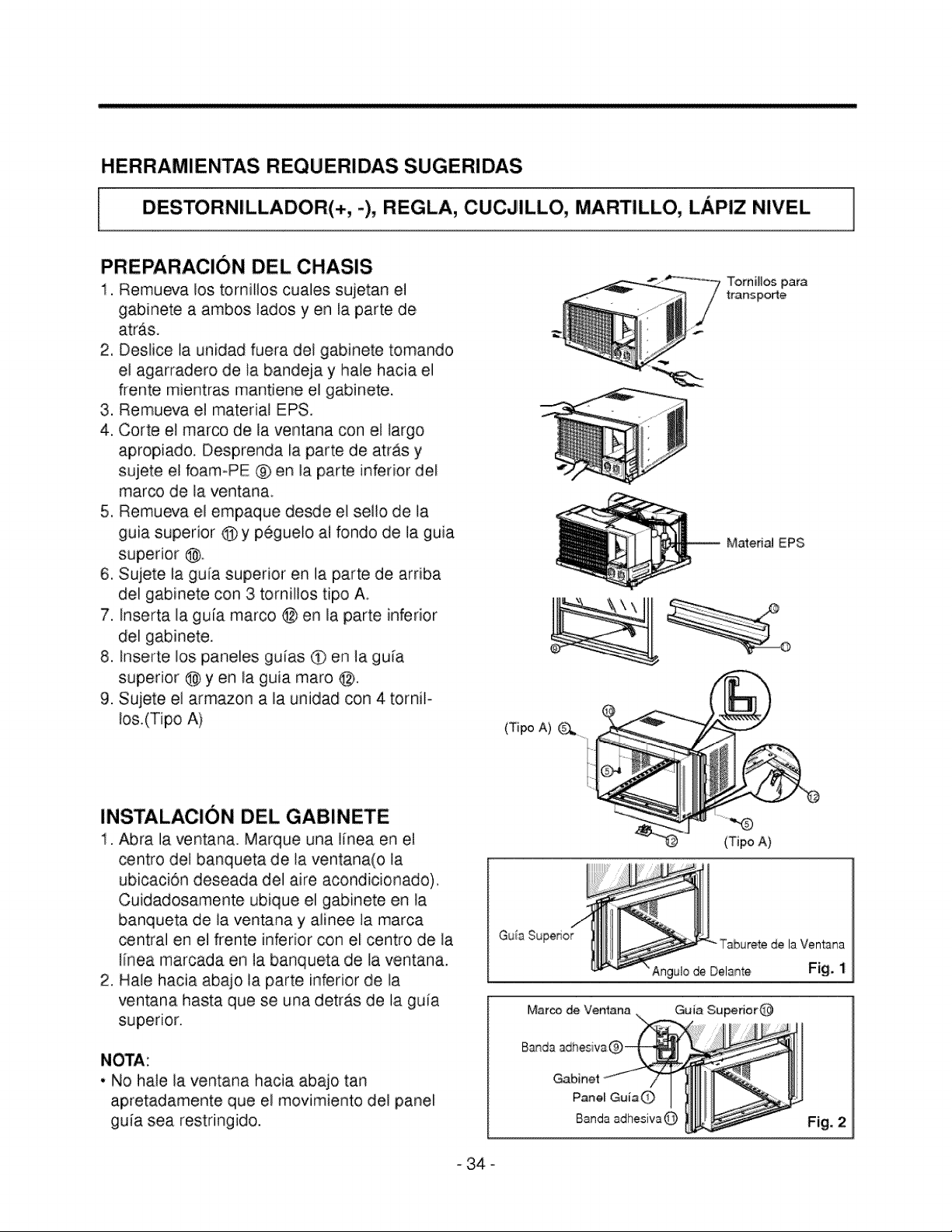
PREPARACION DEL CHASIS
1, Remueva los tornillos cuales sujetan el
gabinete a ambos lados yen la parte de
atr_.s.
2, Deslice la unidad fuera del gabinete tomando
el agarradero de ta bandeja y hale hacia el
ffente mientras mantiene el gabinete.
3. Remueva et material EPS.
4, Corte el marco de la ventana con el largo
apropiado. Desprenda la parte de atras y
sujete el foam-PE @ en la parte inferior del
marco de la ventana.
5, Remueva el empaque desde el sello de la
guia superior @ y peguelo al fondo de la guia
superior @
6, Sujete la gala superior en la parte de arriba
dei gabinete con 3 tornillos tipo A.
7. Inserta la guia marco @ en la parte inferior
del gabinete.
8. Inse_te los paneles gufas • en la guia
superior @ yen Uaguia maro @,
9. Sujete el armazon a la unidad con 4 torniF
Ios.(Tipo A)
INSTALACION DEL GABINETE
1. Abra la ventana. Marque una linea en el
centro del banqueta de la ventana(o la
ubicaci6n deseada del aire acondicionado),
Cuidadosamente ubique el gabinete en la
banqueta de la ventana y alinee la marca
central en el frente inferior con el centro de la
linea marcada en la banqueta de la ventana.
2, Hale hacia abajo la parte inferior de la
ventana hasta que se una detras de la guia
superior.
• No hale la ventana hacia abajo tan
apretadamente que el movimiento dei panel
guia sea restringido.
TomiHos para
trartsporte
Matedal EPS
(Tipo A)
(TipoA)
Gu_aSuperior
Marco de Ventana
de la Ventana
Fig. 1
Fig. 2
- 34 °
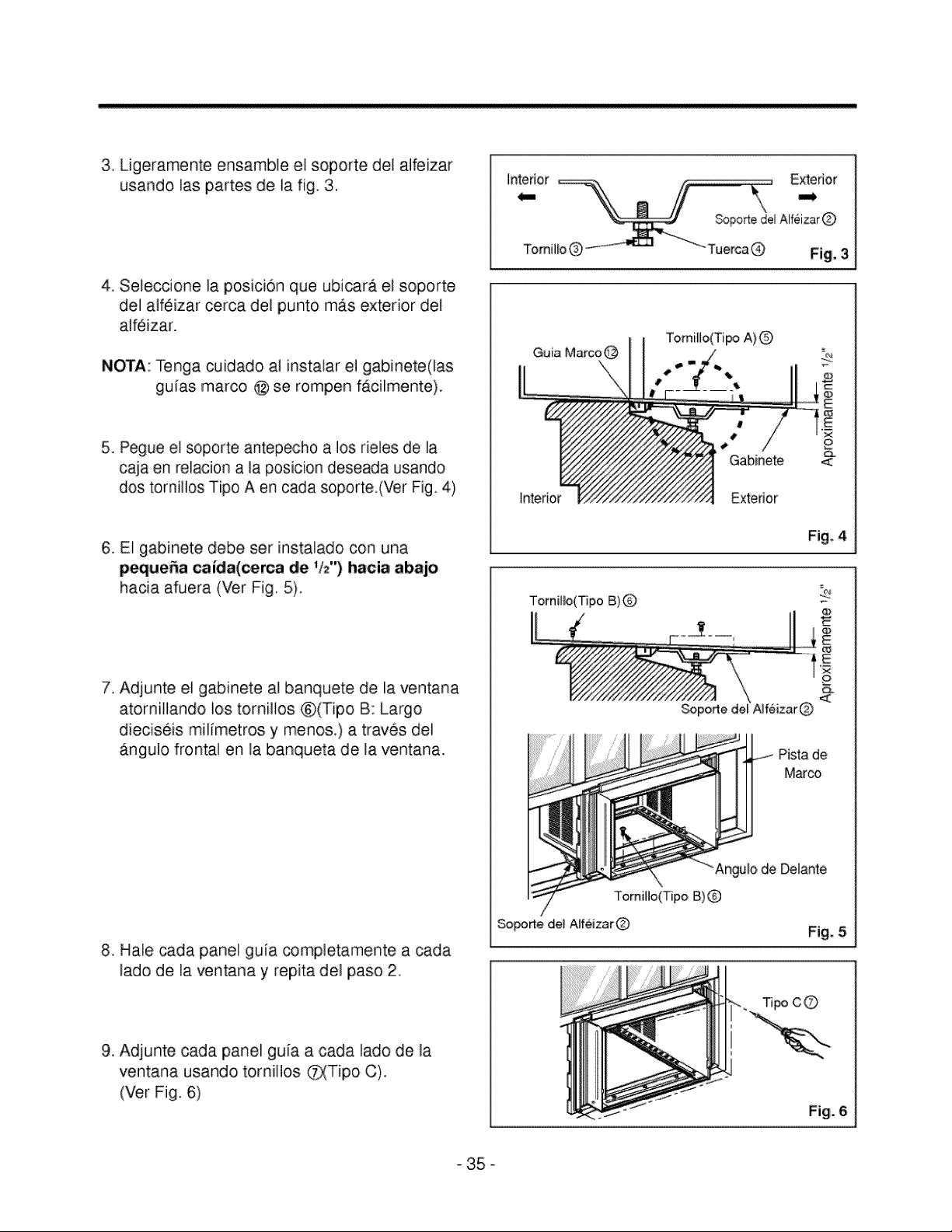
3. Ligeramente ensamble el soporte del alfe[zar
usando las partes de la fig_3,
4, Seleccione la posicion que ubicara el soporte
del a]f6izar cerca de] punto m_s exterior del
alfeizar.
NOTA: Tenga cuidado at [nstalar el gabinete(las
guias marco @ se rompen f_cilmente).
5. Pegue el soporte antepecho a los rie]es de la
caja en relacion a la posicion deseada usando
dos tornillos Tipo A en cada soporte.(Ver Fig. 4)
6. El gabinete debe set instalado con una
peque_a caida(cerca de 1/2") hacia abajo
hacJa afuera (Ver Fig, 5).
7. Adjunte el gabinete al banquete de la ventana
atornillando los tornHIos ®(Tipo B: Largo
dieciseis milimetros y menos,) a traves del
_tngulo frontal en la banqueta de la ventana.
8. Hale cada panel guia completamente a cada
lado de la ventana y repita del paso 2
9. Adjunte cada panel gu[a a cada lado de la
ventana usando tornHIos _Tipo C).
(Ver Fig. 6)
Intedor Exterior
Sopo_e dei AlfeizarQ
Guia Marco@
Interior Extedor
Fig. 4
Tornillo(Tipe B)Q
Angu_ode Delante
TomiHo(T[po B)
Soporte deJ AIf6izar@ Fig. 5
c©
35 o
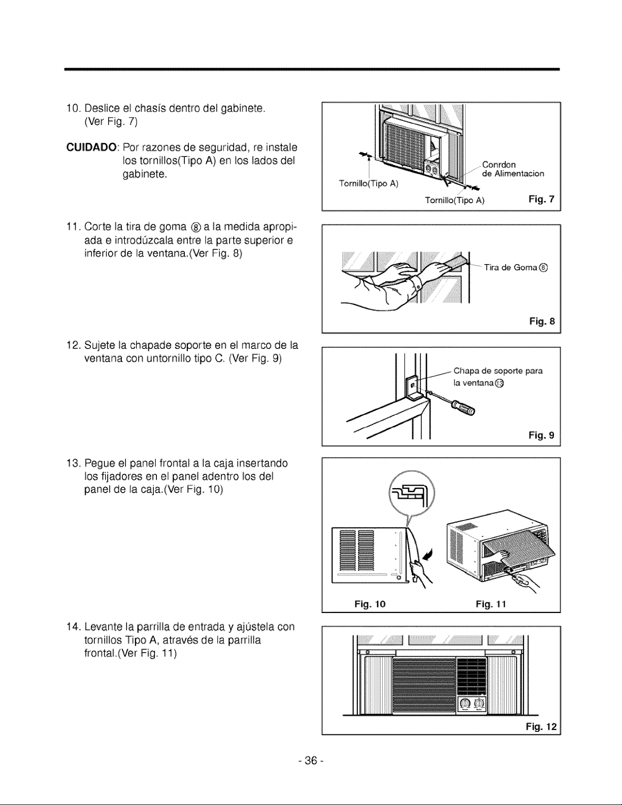
10.Desliceel chasisdentrodel gabinete.
(VetFig.7)
CUIDADO:Potrazonesde seguridad,re instale
lostornillos(TipoA) enlos ladosdel
gabinete.
11.Cortelatira de gomad_a la medidaapropi-
adae introd0zcalaentrela partesuperiore
inferiorde Waventana.(VerFig.8)
12.Sujetelachapadesoporteen el marcode la
ventanaconuntorniIlotipoC. (VetFig9)
13.Pegueel paneJfrontala la cajainsertando
losfijadoresen el paneladentrolosde1
paneide la caja.(VerFig.10)
14.Levantela parrillladeentraday ajOstelacon
tornillosTipoA, atravesde la parrilia
frontal.(VerFig.11)
TorniHo(Ti_ A)
.....Conrdon
....... de A_imenl,acion
TorniHo(Tir_ A} Fig, 7
Tira de GomaQ
F_g.8
soporte para
la ventanaQ
Fig. 9
Fig. 10 Fig. 11
Fig, 12
- 36 °
SEGURIDAD ELECTRICA
• SEGURIDAD ELECTRICA
NSTRUCCIONES DE CONEXiON A TIERRA IMPOR-
TANTES
El aire acondicionado tiene una clavija de conexi6n a
tierra de tres patas en su cable de suminstro de
energia, que devera enchufarse en un tomacorriente
de pared de tres paras conectado a tierra adecuada-
mente para su proteccion contra un posible riesgo de
electrocuci6n.
FUSIBLES: Use un fusible de retardo de tiempo o un
interruptor de circuito. Consulte la placa
de datos para los requisitos del suministro
de energia correcto.
UNIDADES DE 230, 208 y 230/208 VOLTIOS
Estas unidades esta.n equipadas con una clavija de
conexi6n a tierra de tres patas en el cable de sumin-
istro de energia que debera enchufarse en un toma-
corriente de pared para tres patas conectado a tierra
adecuadamente (ver las ilustraciones a continuaci6n)
para su protecci6n contra un posible riesgo de elec-
trocuci6n. Si no tiene un tomacorriente con estas car-
acteristicas, un electricista calificado devera instalar
uno de acuerdo con el C6digo Electrico Nacional y los
c6digos y normas locales.
NOTA: NO USE UN CABLE DE EXTENSION.
- 37 -

Memo
- 38 -
HAM PTON BAY AIR CONDITIONER
LIMITED WARRANTY FOR THE UNITED STATES & CANADA
LG Electronics will repair or at its option replace, without charge, your product which proves tobe
defective in material or workmanship under normal use, during the warranty period listed below
from the date of original purchase. This warranty is good only to the original purchaser of the
product during the warranty period as long as itis in the U.S. including Alaska, Hawaii, and
U.S Territories, and all Canadian Provinces.
WARRANTY PERIOD
MODEL # LABOR PARTS HOW SERVICE IS HANDLED
HBLG1200H 2 Year 2 Year Call 800-984-7469, 24 hrs, a day, 7 days per
COMPRESSOR week. Press the appropriate option, and please
5 Years have your product type(AIR CONDITIONER),
model number, serial number, and ZIP/postal
code ready. All models are in-home service.
No other express warranty is applicable to this product. THE DURATION OF ANY IMPLIED
WARRANTIES, INCLUDING THE IMPLIED WARRANTY OF MERCHANTABILITY, IS LIMITED
TO THE DURATION OF THE EXPRESS WARRANTY HEREIN. LG ELECTRONICS SHALL NOT
BE LIABLE FOR THE LOSS OF THE USE OF THE PRODUCT, INCONVENIENCE, LOSS OR
ANY OTHER DAMAGES, DIRECT OR CONSEQUENTIAL, ARISING OUT OF THE USE OF, OR
INABILITY TO USE, THIS PRODUCT OR FOR ANY BREACH OF ANY EXPRESS OR IMPLIED
WARRANT"(, INCLUDING THE IMPLIED WARRANTY OF MERCHANTABILITY APPLICABLE TO
THIS PRODUCT.
Some states do not allow the exclusion or limitation of incidental or consequential damages or
limitations on how long an implied warranty lasts; so these limitations or exclusions may not apply
to you. This warranty gives you specific legal rights and you may also have other rights which vary
from state to state or province to province.
THE ABOVE WARRANTY DOES NOT APPLY;
• To damages or problems which result from delivery or improper installation.
i ° To damages or problems which result from misues, abuse, accident, alteration, or incorrect
electrical current or voltage.
° To service calls, which do not involve defective workmanship or material, such as explaining the
operation of the unit.
Therefore, these costs are paid bythe consumer.
CUSTOMER ASSISTANCE NUMBERS:
To Prove Warranty Coverage:
..........).
To Obtain Product or Customer -_
Service Assistance:
To Obtain the nearest
Authorized Service Center:
Retain your Sales Receipt to prove date of purchase.
Copy of your Sales Receipt must be submitted atthe time
warranty service is provided.
Call 800-984-7469 (Mon. ~Fri. 7AM-7PM CST)
Press the appropriate menu option, and please have your
product type(AIR CONDITIONER), model number, serial
number, and ZIP/postal code ready.
Call 800-984-7469, 24 hrs, a day, 7 days per week. Press
the appropriate option, and please have your product type _'
(AIR CONDITIONER), and ZIP/postal code ready. _=_
P/No.' 3828A20146S Printed in Korea

