Loading ...
Loading ...
Loading ...
17
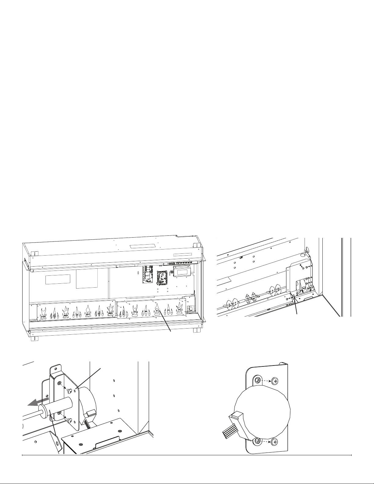
Flicker Motor Replacement
Tools Required: Phillips-Head Screwdriver
1. Follow the instructions for Preparing Firebox for Service on page 10.
2. Remove the 10 screws that secure the ame panel furthest to the right (Figure 13).
3. Remove the 9 screws that secure the icker motor housing (Figure 14).
4. Remove the 2 screws that secure the icker motor bracket to the back panel (Figure 15).
5. Detach the icker rod from the icker motor by carefully exing it and pulling out the rubber sleeve (Figure 15).
6. Remove the 2 screws that secure the icker motor to the icker motor bracket (Figure 16).
7. Trace the wires from the defective icker motor to the main control board.
8. Disconnect the icker motor from the main control board and remove it, cutting any restrictive wire ties.
9. Connect the new icker motor in the correct location on the main control board.
10. Secure the icker motor to the icker motor bracket using the 2 screws previously removed.
11. Secure the icker motor bracket to the back of the rebox, using the 2 screws previously removed.
12. Re-bundle the wires using the provided wire tie.
13. Attach the icker rod to the icker motor.
14. Secure the icker motor housing, using the 9 screws previously removed.
15. Reassemble the rebox.
Remove ame panel Remove ame panel
closest to icker motorclosest to icker motor
Flicker Motor Housing
Flicker Motor BracketFlicker Motor Bracket
Carefully pull out rubber Carefully pull out rubber
sleeve of icker rodsleeve of icker rod
Figure 13
Figure 14
Figure 15
Figure 16
Loading ...
Loading ...
Loading ...