English Manual
PowerSupply&Precautions
CAUTION
WARNING
Make sure your digital piano is rated for the AC voltage supplied in the area
in which the piano will be used. The voltage rating appears on the name plate
on the adaptor.
To ensure proper and safe operation of the instrument, please read the manual
carefully and keep it for future reference.
1) To reduce the risk of fire or electric shock, do not expose this
apparatus to rain or moisture.
2) Please connect the designated DC adaptor to an AC outlet of
the correct voltage.
3) This product should only be used with a standard voltage, if not,
please use an appropriate adaptor that is recommended by the
manufacturer.
4) When opening an
d closing the key cover, be careful not to pinch
hands or fingers.
1) Discharge static electricity by touchingametal surface before
touching the instrument.
2) Protect the keyboard and switches when moving the instrument.
3) Ensure the volume is set to the minimum level before turning on
the instrument.
4) Do not open the inside of the instrument. This instrument contains
precision parts which should not be touched.
5) Turn off the power after use.
6) Unplug the instrument when unused for long periods of time.
7) Do not apply excess force to the buttons and switches.

4
Table of
Contents
Contents
Chapter 1. SP7 Grand Getting Started
1. What’s Included ..................................... 8
2. Power Connection
Chapter 2. Sound Mode
1. Selecting Sounds .................................. 9
1-1 Browse All sounds
1-2 Selecting Sounds by Category ...................... 10
1-3 Selecting a User Sound
1-4 Selecting Sounds by Keyword
/ ID Number Search
Chapter 3. Sound Editing
1. Saving User Sounds .............................. 13
2. Rename a User Sound .......................... 14
3. Controller Editing
3-1 Knob Editing
3-1-1 Assigning a Knob Controller................... 15
3-1-2 Assigning a Knob Color
3-1-3 Assigning a Knob Destination
3-1-3-1 System
3-1-3-2 MIDI CC ......................................... 16
3-1-3-3 AUX FX
3-1-3-4 AUX EQ
3-1-3-5 Zone IFX
3-1-3-6 Audio FX ........................................ 17
3-1-3-7 Vocal Proc
3-1-3-8 Notes
3-1-4 Assigning a Knob Target - ⓐ
3-1-5 Assigning a Knob Min Value - ⓑ
3-1-6 Assigning a Knob Max Value - ⓒ............. 17
3-1-7 Assigning a Knob Initial State - ⓓ
3-1-8 Knob Initial State Send - ⓔ
3-2 Button Editing .................................................. 18
3-2-1 Assigning a Button Controller
3-2-2 Assigning a Button Color
3-2-3 Assigning a Button Destination
3-2-3-1 System ............................................ 19
3-2-3-2 MIDI CC
3-2-3-3 AUX FX
3-2-3-4 AUX EQ ........................................... 20
3-2-3-5 Zone IFX
3-2-3-6 Audio FX
3-2-3-7 Vocal Proc
3-2-3-8 Notes
3-2-4 Assigning a Button Target - ⓐ ................ 21
3-2-5 Assigning a Button Off Value - ⓑ
3-2-6 Assigning a Button On Value- ⓒ
3-2-7 Assigning a Button Initial State - ⓓ
3-2-8 Assigning the Button Type - ⓔ
3-3 Joystick Editing
3-3-1 Assigning the Joystick Controller............ 22
3-3-2 Assigning a Joystick Destination
3-3-3-1 System
3-3-2-2 MIDI CC
3-3-2-3 AUX FX
3-3-2-4 AUX EQ .............................................. 23
3-3-2-5 Zone IFX
3. Controllers ........................................... 11
3-1 X/Y Joystick
3-2 Transpose Button
3-3 Control Knobs ............................................... 12
3-4 Zone Buttons
3-5 SW1(SUSTAIN) and SW2 Pedal
3-6 CC1 (VOLUME) Pedal
2. Touch Screen Display .......................... 11

5
Contents
3-3-2-6 Audio FX
3-3-2-7 Vocal Proc
3-3-2-8 Notes ............................................ 24
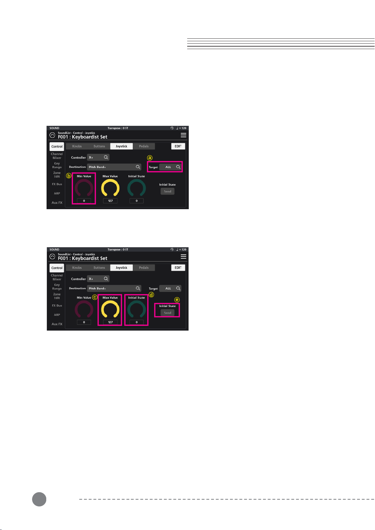
3-3-3 Assigning a Joystick Target - ⓐ
3-3-4 Assigning a Joystick Min Value - ⓑ
3-3-5 Assigning a Joystick Max Value - ⓒ
3-3-6 Assigning a Joystick Initial State - ⓓ
3-3-7 Joystick Initial State Send - ⓔ
3-4 Pedal Editing ................................................. 25
3-4-1 Assigning a Pedal Controller
3-4-2 Assigning Destinations
3-4-2-1 System
3-4-2-2 MIDI CC ........................................ 26
3-4-2-3 AUX FX
3-4-2-4 AUX EQ
3-4-2-5 Zone IFX
3-4-2-6 Audio FX ....................................... 27
3-4-2-7 Vocal Proc
3-4-2-8 Notes
3-4-3 Assigning a Pedal Target - ⓐ
3-4-4 Assigning a Pedal Off Value - ⓑ
3-4-5 Assigning a Pedal On Value - ⓒ
3-4-6 Assigning a Pedal Initial State - ⓓ
3-4-7 Assigning the Pedal Type - ⓔ .............. 28
Table of
Contents
Chapter 4. Multi Sound Editing
4-1 Channel Mixer ............................................... 28
4-1-1 FX Mixer .................................................... 29
4-2 Key Range
4-3 Zone Edit
4-3-1 Common
4-3-1-1 Preset Category ............................ 30
4-3-1-2 Preset Volume
4-3-1-3 ARP Latch
4-3-1-4 Preset BPM
4-3-2 Zone 1-16
4-3-2-1 General
4-3-2-1-1 Program
4-3-2-1-2 Type ...................................... 31
4-3-2-1-3 Activate
4-3-2-1-4 FX Bus
4-3-2-1-5 ARP (Arpeggiator)
4-3-2-1-6 Transpose
4-3-2-1-7 Pan
4-3-2-1-8 Volume
4-3-2-1-9 Destination
4-3-2-2 Keys .............................................. 32
4-3-2-2-1 Velocity Slope
4-3-2-2-2 Velocity Offset
4-3-2-3 Envelope
4-3-2-3-1 Attack .................................... 33
4-3-2-3-2 Decay
4-3-2-3-3 Release
4-3-2-4 Filter
4-3-2-4-1 Cut Off
4-3-2-4-2 Resonance
4-3-2-4-3 Vibrato ................................... 34
4-3-2-4-4 Portamento
4-3-2-4-5 AuxSend
4-3-2-4-6 Misc
4-4 ARP ............................................................... 35
4-4-1 General
4-4-1-1 Key Sort
4-4-1-2 Speed
4-4-1-3 Swing Time
4-4-1-4 Gate Time
4-4-1-5 Velocity Type

6
Table of
Contents
4-4-1-6 Fixed Velocity .................................. 36
4-4-1-7 Fixed Key
4-4-1-8 Key Range
4-4-2 Steps
4-4-2-1 Steps
4-4-2-2 Latch
4-4-2-3 Type
4-4-2-4 Key .................................................. 37
4-4-2-5 Octave
4-4-2-6 Pitch
4-4-2-7 Step Vel.
4-4-2-8 Step Indicator
Chapter 5. FX Editing
5-1 FX Bus ............................................................. 38
5-1-1 Dyn (Dynamic)
5-1-1-1 Compress
5-1-1-2 Distortion
5-1-1-3 Bit Crusher....................................... 39
5-1-2 P.EQ
5-1-3 Mod/Wah
5-1-3-1 Rotary .............................................. 40
5-1-3-2 Chorus
5-1-3-3 Vibrato
5-1-3-4 Flanger ............................................. 41
5-1-3-5 Phaser
5-1-3-6 Wah-Wah
5-1-4 Dly/Trm (Delay/Tremolo) ......................... 42
5-1-4-1 Delay
5-1-4-2 Tremolo
5-1-5 Mix ........................................................... 43
5-2 AUX FX
5-2-1 Delay
Chapter 6. Favorite Mode
6-1 Assigning Favorites
6-2 Recalling Favorites
Chapter 7. Audio Mode
7-1 General ......................................................... 46
7-2 Input 1, 2 ...................................................... 47
7-2-1 Input
7-2-2 Dyn (Dynamic)
7-2-3 P.EQ
7-2-4 Mod/Wah (Modulation, Wah) ................ 48
7-2-5 Mix
7-3 In 1, 2 Vocal Proc
7-3-1 Lead Processing
7-3-1-1 Octave .......................................... 49
7-3-1-2 Gender
7-3-1-3 Mode
7-3-1-4 Chromatic Scale
7-3-1-5 Smooth/Pitch
7-3-1-6 Vib.Style
7-3-1-7 Vib.Rate (Vibrato Rate)
7-3-1-8 Vib.Depth (Vibrato Depth)
7-3-1-9 Vib.Delay (Vibrato Delay)
7-3-2 Auto Harmony ...................................... 50
7-3-2-1 Auto Gender
7-3-2-2 Key
7-3-2-3 Scale
7-3-2-4 Humanization
7-3-2-5 Portamento
7-3-2-6 Volume
5-2-2 Chorus .................................................. 44
5-2-3 Reverb
5-2-4 Equalizer ............................................... 45
Contents

Contents
7
Table of
Contents
7-3-2-7 Harmony Voices
Chapter 8. Global Mode
8-1 Global 1 .......................................................... 51
8-1-1 Master Tune
8-1-2 Auto Power Off
8-1-3 Tempo Mode
8-1-4 Velocity Map (refer to Appendix 2)
8-1-5 MIDI TX Mode ......................................... 52
8-1-6 MIDI RX Mode
8-1-7 Override
8-2 Global 2
8-2-1 Blink Tempo
8-2-2 LCD Bright
8-2-3 LED Bright
8-2-4 String Resonance .................................... 53
8-2-5 Damper Resonance
8-3 Global Control
8-4 LED Color
8-5 Demo Song
8-6 Info .................................................................. 54
8-7 Menu ............................................................... 54
Supplementary Provisions (1)
.....................................
55
Supplementary Provisions (2)
.....................................
56
Product Specification
..................................................
57
Memo
.........................................................................
58
Contents
8
Chapter 1. Started
Chapter 1. SP7 Grand Getting Started
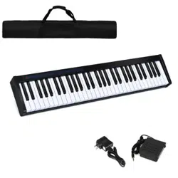
Included with the purchase of the SP7 Grand:
※ The shape of the plug may differ depending on global region.
If any of the above accessories are missing, please contact your KURZWEIL dealer. When transport-
ing the SP7 Grand, we recommend using a protective keyboard case or gig bag.
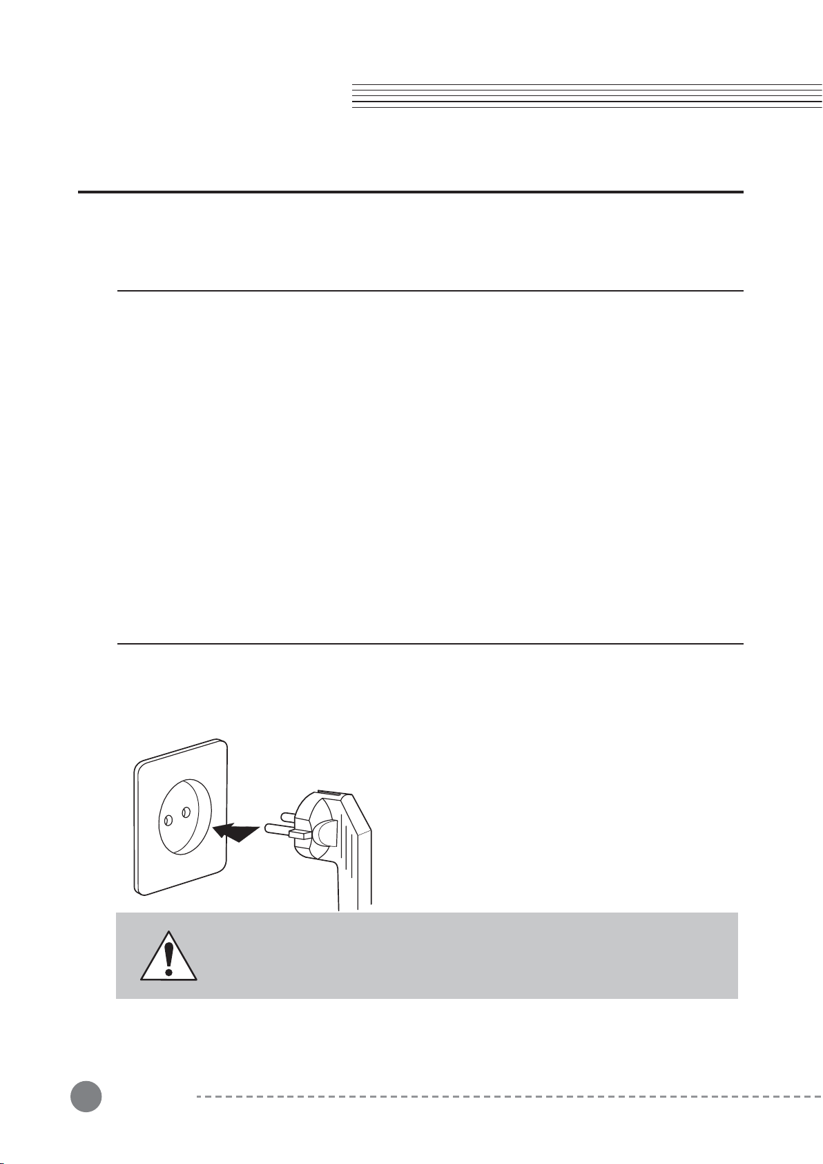
To turn on the power, press the power button which is located on the right side of the back panel
(when seated in front of the SP7 Grand).
The SP7 Grand uses a DC power adapter.
After connecting the power adapter to the rear panel, plug the AC power cord into a wall outlet.
- SP7 Grand stage piano
- DC power adapter, AC power cord
- Sustain pedal
- Product warranty
- SP7 Grand User Manual (this booklet)
- USB cable, Smart Recording cable, balance cables, SD card
1. What’s Included
2. Power Connection
CAUTION: Be sure to use the supplied DC power adapter (15V, 2.5A).
Using the wrong DC power adapter may damage the product.
If the adapter is damaged or missing, contact your KURZWEIL dealer.
Chapter 1
9
Chapter 2
Chapter 2. Sound Mode
Chapter 2. Sound Mode
Sound mode is the default at power up and is the mode used for exploring the various multi Sound
combinations available in the SP7 Grand. The SP7 Grand offers 512 multi combination Sounds
drawing from a pool of 301 high-quality individual programs (many extracted from Kurzweil's flagship
K2700 workstation).
To return to Sound mode from any other mode, press the Sound mode button, the second of the
four mode buttons on the right side of the touch screen.
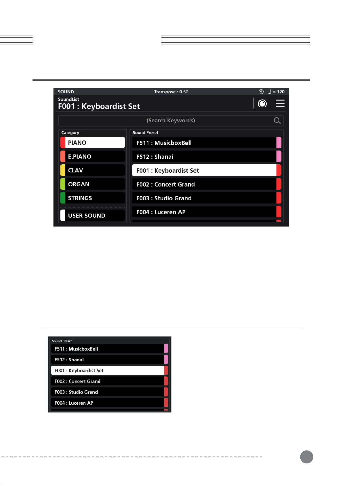
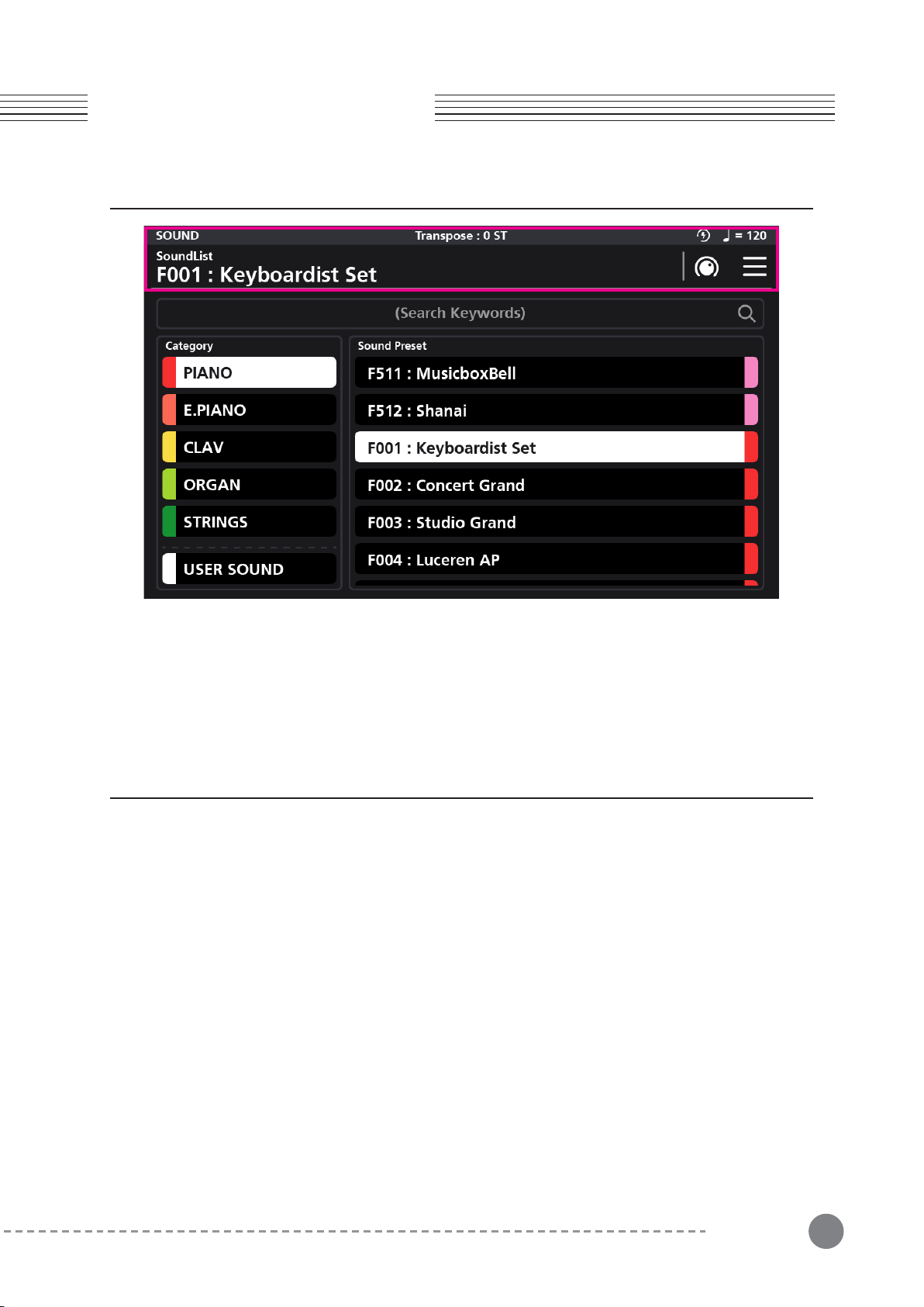
1-1 Browse all sounds
In Sound mode, the preset list is displayed on
the right side of the screen. To make a selection
you can either scroll with your finger through the
list and tap a desired selection, use the Alpha
wheel and/or the Increase (+) and Decrease (-)
buttons.
1. Selecting Sounds
10
Chapter 2. Sound Mode
Chapter 2
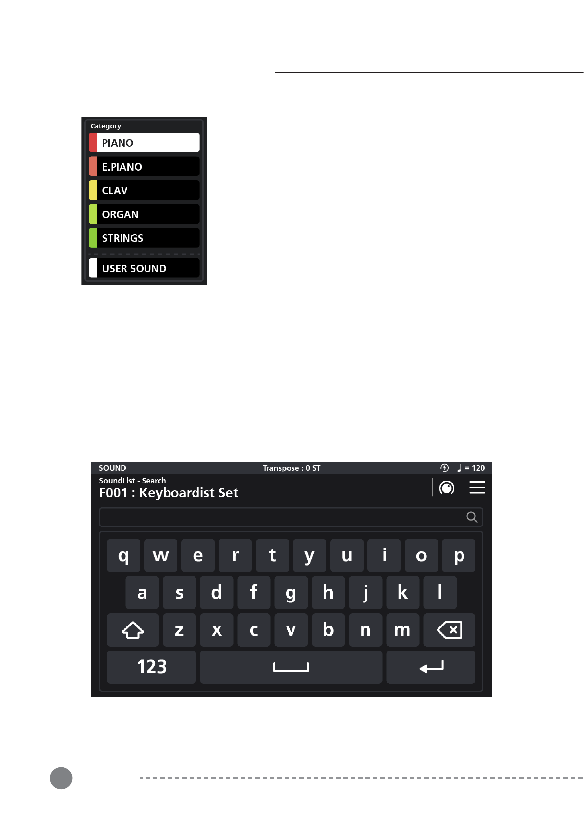
1-2 Selecting Sounds by Category
The sound presets are organized into 14 categories by type: PIANO,
E.PIANO, CLAV, ORGAN, STRING, PAD, ENSEMBLE, BRASS,
WINDS, SYNTH, GUITAR/BASS, DRUMS/PERC, MISC, and USER.
You can select a category by pressing the desired front panel
Category button or by scrolling down the list in the left part of the
screen and then tapping your selection.
When a category is selected, all associated sounds of that category
are displayed in a list on the right side of the screen. You can then
select a specific sound by dragging/tapping through the sound list,
use the Alpha wheel and/or the Increase (+) and Decrease (-)
buttons.
1-3 Selecting a User Sound
Sounds you have edited and saved are stored in the User category. You can access the User
category either by pressing the front panel User Category button or by tapping the on screen User
Sound category tab in the lower left corner of the screen. If there are no Sounds yet stored in the
User area you will see “There is no user preset” displayed in the top center of the screen.
1-4 Selecting Sounds by Keyword / ID Number Search
Touch the (Search Keywords) field at the top center of the screen to reveal a keyboard where you
can type in a name or sound ID number to search by (the search is not case sensitive).
Chapter 2. Sound Mode
11
2. Touch Screen Display
Chapter 2
In Sound mode, the top line of the screen displays the currently selected mode, current sound,
transpose status, MIDI in/out activity, auto power off and tempo information. The column on the
left shows the list of Sound Categories and the column on the right displays the presets within the
given category. The display is a touch screen and most operations can be selected and changed
with a simple touch.
3. Controllers
The SP7 Grand offers a variety of physical controllers that can be used to enhance one’s musical
performance by varying an instrument's characteristics in real-time.
Controllers include knobs, buttons, X/Y joystick and pedals.
3-1 X/Y Joystick
The joystick is a multi-purpose up/down/left/right XY programmable controller that allows you to
control various functions and FX while performing. By default the x-axis controls pitch and the
y-axis controls modulation.
3-2 Transpose Button
Use the Transpose buttons to play in different musical keys. Each press of the + button raises the
key by one semitone (half step). Conversely, each press of the - button lowers the key by one
semitone.
Press both buttons at the same time to return to the non-transposed state of 0.

12
Chapter 2
Chapter 2. Sound Mode
3-3 Control Knobs
A group of 8 customizable LED colored knobs are located to the upper left of the touch screen.
The default controller assignments are: EQ Lo, EQ Mid Lo, EQ Mid Hi, EQ Hi, Delay Time, Delay
Level, Reverb Time, and Reverb Level. These functions can be customized. Adjusting the knobs
alters the values of corresponding graphic parameters displayed on screen.
3-4 Zone Buttons
A group of 8 customizable LED colored buttons are located to the lower left of the touch screen.
By default, these mute and unmute the various Zones which make up the current multitimbral
sound. These button functions can also be customized.
3-5 SW1 (SUSTAIN) and SW2 Pedal
The SW1 (SUSTAIN) pedal defaults to controlling piano sustain, which will sustain any note that is
played while the pedal is pressed, for as long as the pedal is held.
The SW2 pedal defaults to controlling Sostenuto, which will only sustain notes for keys that are
being held down before the pedal is pressed, for as long as the pedal is held.
The SW1 (SUSTAIN) and SW2 pedals can be enabled, disabled or reassigned for each Sound in
the Sound Edit mode. In Global mode, you can also set up controller overrides that allow you to
change the switch pedal assignments for all Sounds.
3-6 CC1 (VOLUME) Pedal
The CC (VOLUME) pedal defaults to controlling volume (pre-FX).
For Organ sounds, the CC (VOLUME) pedal controls organ swell. Organ swell is similar to volume,
except the pedal operates over a narrower range and cannot be turned all the way down to
silence.
The CC (VOLUME) pedal can be enabled, disabled, or reassigned for each Sound in Sound Edit
Mode.
Global Mode can be used to set pedal overrides, which can change the CC pedal assignment for
all Sounds.
13
Chapter 3
Chapter 3. Sound Editing
Chapter 3. Sound Editing
Use Sound Edit mode to edit and save custom sounds to a user ID for later recall.
In Favorite mode or Sound mode, press the knob shaped icon in the upper right hand corner of the
touch screen to enter Sound Edit mode.
Adjust all parameter dials by touch, alpha wheel (once selected), Increase+/Decrease- buttons, or
tap the value field to open a numeric keypad for more precise data entry.
1. Saving User Sounds
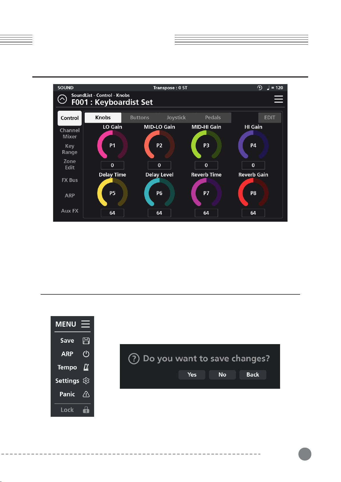
Whenever changes are made to a sound within the Edit menu, it becomes
possible to save that edited sound as a new User sound. To save, tap the
MENU button in the upper right hand corner which reveals a list of options.
Click the “Save" button.
When you click the Save button, a save confirmation dialog window appears,
“Do you want to save changes?” If you do not want to save the changes,
press the “No” button. If you do want to save the changes, press the “Yes”
button. If you want to return to the previous step, press the “Back” button.
14
Chapter 3
Chapter 3. Sound Editing
2. Rename a User Sound
3. Controller Editing
You have the option to rename a user sound during the saving process. Before pressing “Okay”,
press the “Rename” button and a pop-up keyboard will appear allowing you to enter the new
name. Press “Save” when done.
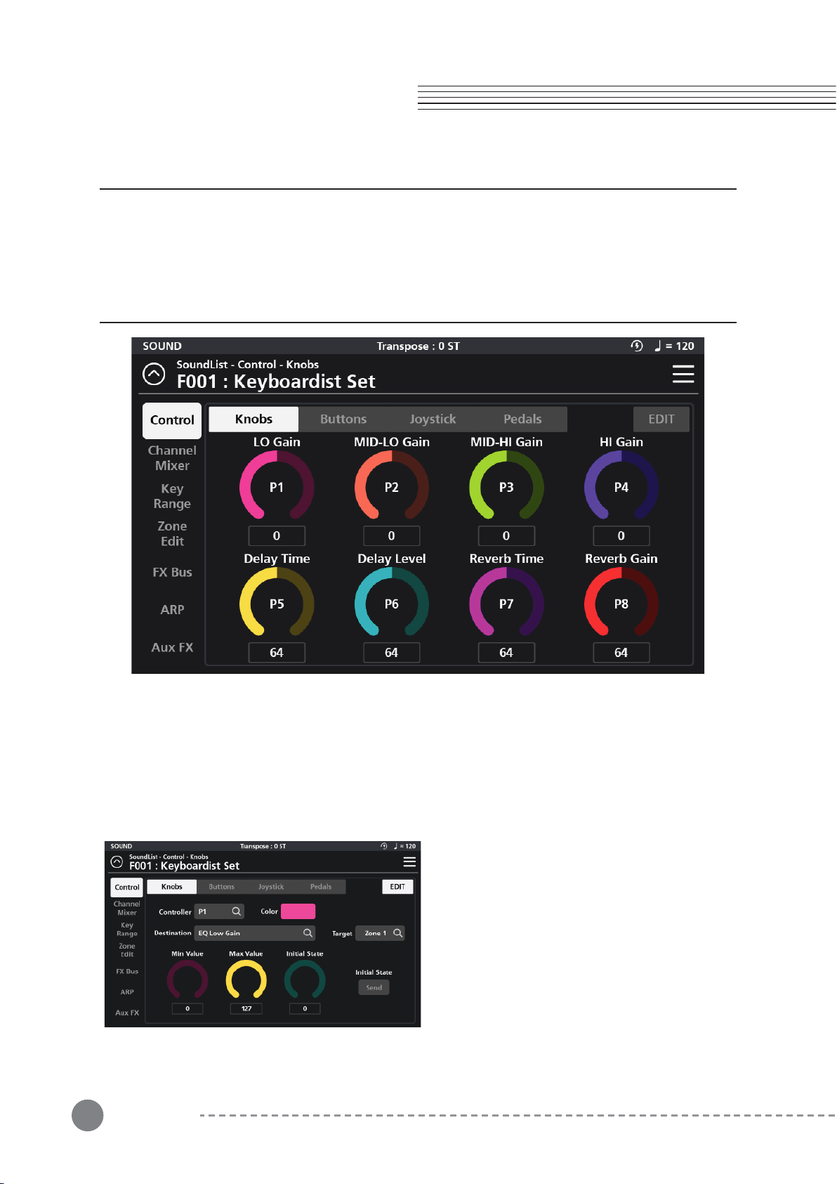
Select the “Control” tab in the top left corner to access the various Controller assignment pages:
Knobs, Buttons, Joystick, and Pedals. To assign a controller, tap the desired Controller type. The
initial page displays an overview of the chosen controller type and the current assignments. To
make a change, click the “EDIT” button at the top right to go to the corresponding controller
editing page.
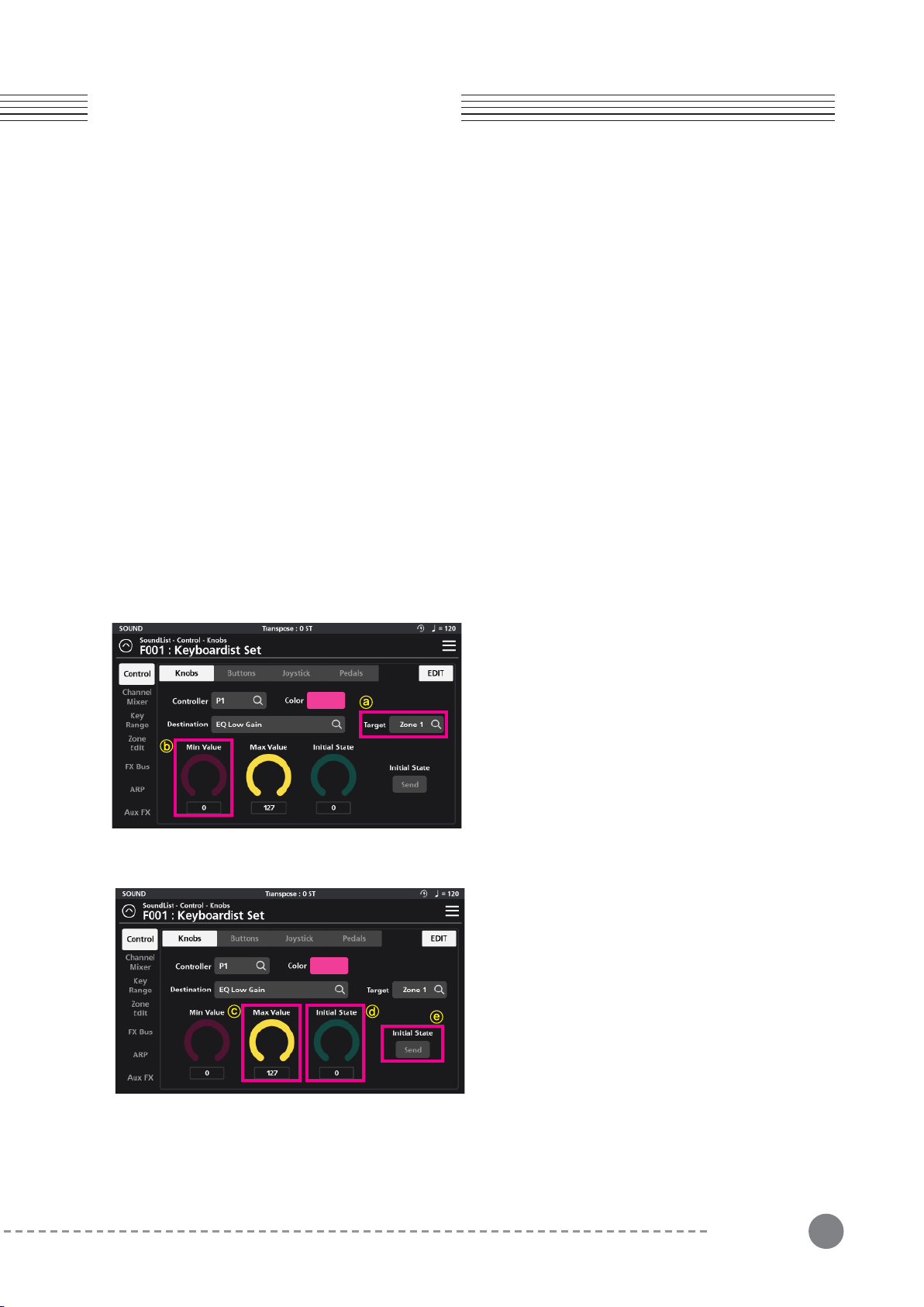
There are 8 control knobs on the SP7 Grand, labeled
P1 to P8. On the “Knob” Edit page, you can select
the Controller knob to edit, edit the Knob Color,
Destination, Target, Min/Max Value, Initial State
value and Send State.
3-1 Knob Editing
15
Chapter 3
Chapter 3. Sound Editing
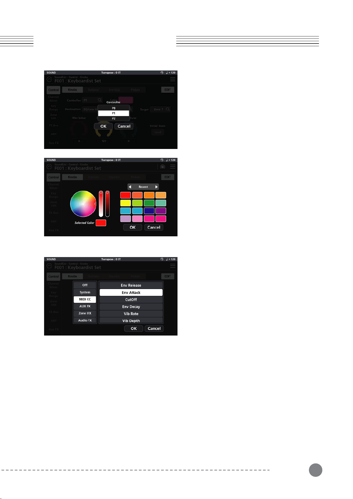
3-1-1 Assigning a Knob Controller
Tap the Controller field and select the desired Knob (P1
to P8) you want to assign. Selecting a given Knob
displays that knob’s parameters on screen.
3-1-2 Assigning a Knob Color
Change the color of the knob LED ring by tapping the
Color tile and, on the following screen, dragging the
small circle about in the color palette wheel. Adjust the
contrast and brightness using the two adjacent vertical
control bars.
On the right you can also select between three groups
of color palettes: The Default color set, a set of Pastels,
and the most Recently used colors. The most recently
used set are automatically saved for convenient
repeated selection. Press OK to commit your selection.
3-1-3 Assigning a Knob Destination
The Destination parameter specifies the function of the
given Knob. Tap the Destination field to access the
function assignment page where you will be presented
with 8 Destination types to choose from: System, MIDI
CC, AUX FX, AUX EQ, Zone IFX, Audio FX, Vocal Proc
and Notes.
3-
1-3-1 System
The “System” tab offers a total of 9 possible choices:
Ctrl Override: When enabled*, all controller assignments mapped within the current Sound are overridden and
take on the Global mode settings instead.
*Caution: Once enabled, the only means to disable this controller is to go to Global mode (Global 1 page) and
manually set the “Override Controller” switch back to Off.
Blink Tempo: Enables the Alpha wheel LED ring to “blink” (strobe) along with the current Global BPM tempo.
ARP Enable: Turns the arpeggiator on/off. (Note: for an arp to run, one of the 8 available arps must first be
assigned to the zone in question on the Zone Edit page - see pg 31 for more detail).
ARP Latch: This destination controls the “Arp Latch” master switch (Zone Edit / Common page). When engaged,
this allows any Arp (A-H), that has its individual “Latch” parameter (ARP / Steps menu) set to “On”, to continue
to play its pattern even after all piano keys have been released.

16
Chapter 3. Sound Editing
Chapter 3
3-1-3-2 MIDI CC
The full compliment of 128 Standard MIDI CCs can be assigned by selecting from a drop down scroll list.
3-1-3-3 AUX FX
The “Aux FX” tab offers 13 possible destinations governing the AUX FX section:
Reverb Size : Controls the size of the reverberant space.
Reverb Level : Controls the amount of reverb.
Reverb Time : Controls the length of reverb decay.
Chorus Level : Controls the amount of the chorus effect.
Chorus Feedback : Controls the level of chorus feedback.
Chorus Rate : Controls the speed of chorus modulation.
Chorus Depth : Controls the maximum detuning range of the chorus modulation.
Cho To Rev : Controls the amount of Chorus fed into the Reverb.
Delay Level : Controls the amount of delay.
Delay Time : Controls the interval of time it takes for the sound to repeat.
Delay Feedback : Controls the amount of delay feedback.
Dly To Rev : Controls the amount of Delay fed into the Reverb.
Dly To Cho : Controls the amount of Delay fed into the Chorus.
3-1-3-4 AUX EQ
The Aux EQ tab offers adjustments covering the 4 frequency bands of the Aux EQ:
EQ Low Gain : This function adjusts the low frequency range.
EQ Mid Low Gain : This function adjusts the low-mid frequency range.
EQ Mid High Gain : This function adjusts the high-mid frequency range.
EQ High Gain : This function adjusts the high frequency range.
3-1-3-5 Zone IFX (Zone Insert Effect)
The “Zone IFX” tab offers 4 possible destinations governing the IFX Mixer:
Output Volume : This function controls the volume level of the post IFX/pre Aux FX signal.
Pan : This function adjusts the left/right balance of the post IFX/pre Aux FX signal.
Reverb Send : This function controls the amount of post IFX sent to the Aux Reverb.
ChoDly Send : This function controls the amount of post IFX signal sent to the Aux Chorus and Delay.
Global BPM: This is the tempo (expressed in Beats Per Minute) applied to the entire instrument.
Pitch Bend+, Pitch Bend- : MIDI pitch bend control.
Program Change : Specify a MIDI program change (0-127) to select a given sound.Zone Activate : Enables/dis-
ables a zone.
17
Chapter 3
Chapter 3. Sound Editing
3-1-3-6 Audio FX
The “Audio FX” tab offers 4 possible destinations governing the Audio Input Mixer:
Output Volume : This function controls the volume level of the post IFX/pre Aux FX signal.
Pan : This function adjusts the left/right balance of the post IFX/pre Aux FX signal.
Reverb Send : This function controls the amount of post IFX sent to the Aux Reverb.
ChoDly Send : This function controls the amount of post IFX signal sent to the Aux Chorus and Delay.
3-1-3-7 Vocal Proc (Vocal Processor)
The Vocal Processor tab offers 3 possible destinations governing the Vocal Processor section:
Lead Process On/Off : This function turns the Lead Processing section on/off.
Auto Harm On/Off : This function turns the Auto Harmony section on/off.
Auto Harm Volume : This function controls the volume level of the Auto Harmony section.
3-1-3-8 Notes
The Notes tab allows you to select individual MIDI note numbers (#0-127) to trigger from the selected controller
knob. The selected note will be triggered throughout the rotation of the knob. The note velocity is determined by
the Max Value. This function can be usefully for triggering percussion hits and sound effects.
3-1-4 Assigning a Knob Target - ⓐ
A Knob’s operating region is determined by its Target
assignment. Depending on the chosen Destination,
Target selection options can be: None, Preset, System,
Zone1~16, Zone ALL, FX A~D, FX ALL, Input 1~2 and
Input ALL.
3-1-5 Assigning a Knob Min Value - ⓑ
Sets the minimum adjustable value of the controller
knob (value range = 0-127).
3-1-6 Assigning a Knob Max Value - ⓒ
Sets the maximum adjustable value of the controller
knob (value range = 0-127).
3-1-7 Assigning a Knob Initial State - ⓓ
If the Initial State Send is enabled, the Initial State is the
starting value (0-127) applied to the given knob when a
Sound is first selected.
3-1-8 Knob Initial State Send - ⓔ
With the Initial State Send enabled, the Initial State
value (above) is set as the knob starting point when a
Sound is first selected.
18
Chapter 3. Sound Editing
Chapter 3
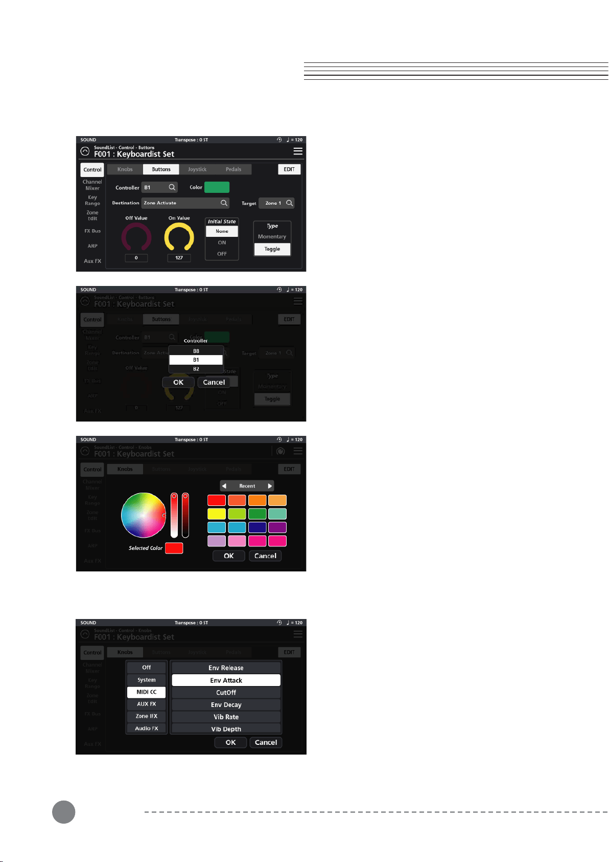
3-2-1 Assigning a Button Controller
Tap the Controller field and select the desired Button
(B1-B8) to assign. Selecting a given button displays
that button’s parameters on screen.
3-2 Button Editing
There are eight programmable controller buttons on the
SP7 Grand, labeled B1 to B8. On the “Buttons” Edit
page you can change the Color, assign a Destination,
change the Target, set the Min/Max values, Initial State
and button behavior Type.
3-2-2 Assigning a Button Color
Change the color of the selected button by tapping the
Color tile and, on the following screen, dragging the
small circle about in the color palette wheel.
Adjust the contrast and brightness using the two
adjacent vertical control bars.
On the right you can also select between three groups
of color palettes: The Default color set, a set of Pastels,
and the most Recently used colors. The most recently
used set are automatically saved for convenient
repeated selection.
Press OK to commit your selection.
3-2-3 Assigning a Button Destination
The Destination parameter specifies the function of the
given Button. Tap the Destination field to access the
function assignment page where you will be presented
with 8 Destination types to choose from: System, MIDI
CC, AUX FX, AUX EQ, Zone IFX, Audio FX, Vocal Proc
and Notes.

19
3-2-3-1 System
The “System” tab offers a total of 9 possible choices:
Ctrl Override: When enabled*, all controller assignments mapped within the current Sound are overridden and
take on the Global mode settings instead.
*Caution: Once enabled, the only means to disable this controller is to go to Global mode (Global 1 page) and
manually set the “Override Controller” switch back to Off.
Blink Tempo: Enables the Alpha wheel LED ring to “blink” (strobe) along with the current Global BPM tempo.
ARP Enable: Turns the arpeggiator on/off. (Note: for an arp to run, one of the 8 available arps must first be
assigned to the zone in question on the Zone Edit page - see pg 31 for more detail).
ARP Latch: This destination controls the “Arp Latch” master switch (Zone Edit / Common page). When engaged,
this allows any Arp (A-H), that has its individual “Latch” parameter (ARP / Steps menu) set to “On”, to continue
to play its pattern even after all piano keys have been released.
Global BPM: This is the tempo (expressed in Beats Per Minute) applied to the entire instrument.
Pitch Bend+, Pitch Bend- : MIDI pitch bend control.
Program Change : Specify a MIDI program change (0-127) to select a given sound.Zone Activate : Enables/dis-
ables a zone.
3-2-3-2 MIDI CC
The full compliment of 128 Standard MIDI CCs can be assigned by selecting from a drop down scroll list.
3-2-3-3 AUX FX
The “Aux FX” tab offers 13 possible destinations governing the AUX FX section:
Reverb Size : Controls the size of the reverberant space.
Reverb Level : Controls the amount of reverb.
Reverb Time : Controls the length of reverb decay.
Chorus Level : Controls the amount of the chorus effect.
Chorus Feedback : Controls the level of chorus feedback.
Chorus Rate : Controls the speed of chorus modulation.
Chorus Depth : Controls the maximum detuning range of the chorus modulation.
Cho To Rev : Controls the amount of Chorus fed into the Reverb.
Delay Level : Controls the amount of delay.
Delay Time : Controls the interval of time it takes for the sound to repeat.
Delay Feedback : Controls the amount of delay feedback.
Dly To Rev : Controls the amount of Delay fed into the Reverb.
Dly To Cho : Controls the amount of Delay fed into the Chorus.
Chapter 3
Chapter 3. Sound Editing

20
Chapter 3. Sound Editing
Chapter 3
3-2-3-4 AUX EQ
The Aux EQ tab offers adjustments covering the 4 frequency bands of the Aux EQ:
EQ Low Gain : This function adjusts the low frequency range.
EQ Mid Low Gain : This function adjusts the low-mid frequency range.
EQ Mid High Gain : This function adjusts the high-mid frequency range.
EQ High Gain : This function adjusts the high frequency range.
3-2-3-5 Zone IFX (Zone Insert Effect)
The “Zone IFX” tab offers 4 possible destinations governing the IFX Mixer:
Output Volume : This function controls the volume level of the post IFX/pre Aux FX signal.
Pan : This function adjusts the left/right balance of the post IFX/pre Aux FX signal.
Reverb Send : This function controls the amount of post IFX sent to the Aux Reverb.
ChoDly Send : This function controls the amount of post IFX signal sent to the Aux Chorus and Delay.
3-2-3-6 Audio FX
The “Audio FX” tab offers 4 possible destinations governing the Audio Input Mixer:
Output Volume : This function controls the volume level of the post IFX/pre Aux FX signal.
Pan : This function adjusts the left/right balance of the post IFX/pre Aux FX signal.
Reverb Send : This function controls the amount of post IFX sent to the Aux Reverb.
ChoDly Send : This function controls the amount of post IFX signal sent to the Aux Chorus and Delay.
3-2-3-7 Vocal Proc
The Vocal Processor tab offers 3 possible destinations governing the Vocal Processor section:
Lead Process On/Off : This function turns the Lead Processing section on/off.
Auto Harm On/Off : This function turns the Auto Harmony section on/off.
Auto Harm Volume : This function controls the volume level of the Auto Harmony section.
3-2-3-8 Notes
The Notes tab allows you to select individual MIDI note numbers (#0-127) to trigger from the selected controller
button. The note velocity is determined by the Max Value. This function can be usefully for triggering percussion
hits and sound effects.
21
Chapter 3
Chapter 3. Sound Editing
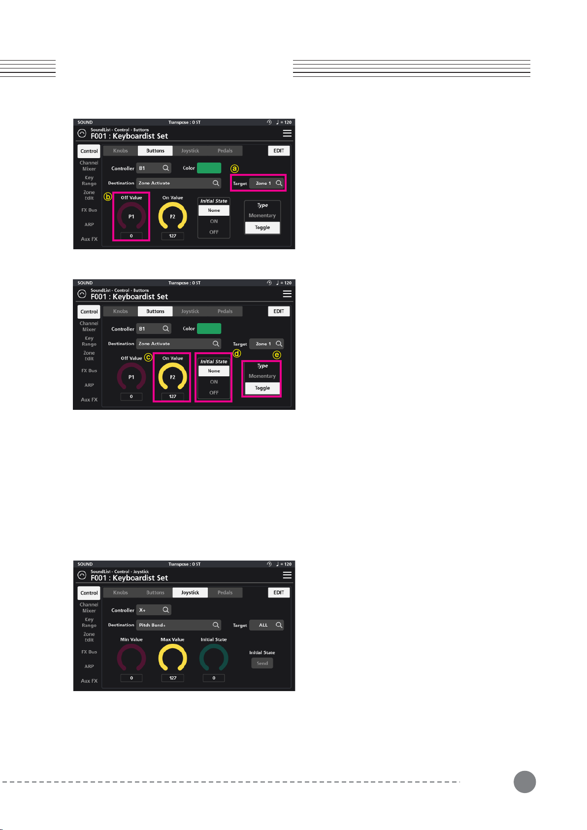
3-2-4 Assigning a Button Target - ⓐ
A Button’s operating region is determined by its Target
assignment. Depending on the chosen Destination,
Target selection options can be: None, Preset, System,
Zone1~16, Zone ALL, FX A~D, FX ALL, Input 1~2 and
Input ALL.
3-2-5 Assigning a Button Off Value - ⓑ
The Off value is the value (0-127) sent when the given
Button is turned Off (dim).
3-2-6 Assigning a Button On Value- ⓒ
The On Value is the value (0-127) sent when the given
Button is turned On (lit).
3-2-7 Assigning a Button Initial State - ⓓ
The Initial State establishes a given button’s default
starting point when a sound is first selected. “None”
sets no initial state and, as such, will adopt the state (on
or off) of that same button from the previously selected
sound. A setting of On or Off specifically sets the
button to On (lit) or Off (dim) when the sound is first
selected.
3-2-8 Assigning the Button Type - ⓔ
Use the Type parameter to set the button behavior to Momentary or Toggle.
When Type is set to Momentary, the button sends its “On Value” when pressed, and its “Off Value” when
released.
When Type is set to Toggle, the button alternates between sending its “On Value” or “Off Value” each time it is
pressed. No value is sent when the controller is released.
The X/Y joystick of SP7 Grand consists of four inde-
pendently programmable directions: Left (X-), Right
(X+), Up (Y+), and Down (Y-). On the “Joystick” Edit
page, you can edit the Destination, Target, Min/Max
value and Initial State for each of the four joystick
directions.
3-3 Joystick Editing
22
Chapter 3. Sound Editing
Chapter 3
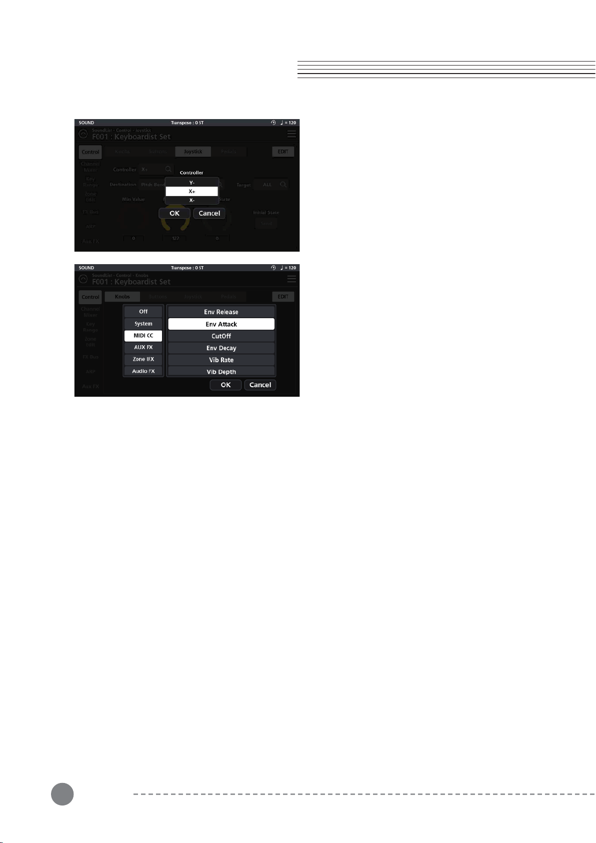
3-3-1 Assigning the Joystick Controller
Tap the Controller field and select the desired joystick
direction: X+, X-, Y+ or Y- by tapping on the touch
screen. Press OK to commit.
3-3-2 Assigning a Joystick Destination
The Destination parameter specifies the function of the
given joystick direction. Tap the Destination field to
access the function assignment page where you will be
presented with 8 Destination types to choose from:
System, MIDI CC, AUX FX, AUX EQ, Zone IFX, Audio
FX, Vocal Proc and Notes.
3-3-2-1 System
The “System” tab offers a total of 9 possible choices:
Ctrl Override: When enabled*, all controller assignments mapped within the current Sound are overridden and
take on the Global mode settings instead.
*Caution: Once enabled, the only means to disable this controller is to go to Global mode (Global 1 page) and
manually set the “Override Controller” switch back to Off.
Blink Tempo: Enables the Alpha wheel LED ring to “blink” (strobe) along with the current Global BPM tempo.
ARP Enable: Turns the arpeggiator on/off. (Note: for an arp to run, one of the 8 available arps must first be
assigned to the zone in question on the Zone Edit page - see pg 31 for more detail).
ARP Latch: This destination controls the “Arp Latch” master switch (Zone Edit / Common page). When engaged,
this allows any Arp (A-H), that has its individual “Latch” parameter (ARP / Steps menu) set to “On”, to continue
to play its pattern even after all piano keys have been released.
Global BPM: This is the tempo (expressed in Beats Per Minute) applied to the entire instrument.
Pitch Bend+, Pitch Bend- : MIDI pitch bend control.
Program Change : Specify a MIDI program change (0-127) to select a given sound.Zone Activate : Enables/dis-
ables a zone.
3-3-2-2 MIDI CC
The full compliment of 128 Standard MIDI CCs can be assigned by selecting from a drop down scroll list.
3-3-2-3 AUX FX
The “Aux FX” tab offers 13 possible destinations governing the AUX FX section:

23
Chapter 3
Chapter 3. Sound Editing
Reverb Size : Controls the size of the reverberant space.
Reverb Level : Controls the amount of reverb.
Reverb Time : Controls the length of reverb decay.
Chorus Level : Controls the amount of the chorus effect.
Chorus Feedback : Controls the level of chorus feedback.
Chorus Rate : Controls the speed of chorus modulation.
Chorus Depth : Controls the maximum detuning range of the chorus modulation.
Cho To Rev : Controls the amount of Chorus fed into the Reverb.
Delay Level : Controls the amount of delay.
Delay Time : Controls the interval of time it takes for the sound to repeat.
Delay Feedback : Controls the amount of delay feedback.
Dly To Rev : Controls the amount of Delay fed into the Reverb.
Dly To Cho : Controls the amount of Delay fed into the Chorus.
EQ Low Gain : This function adjusts the low frequency range.
EQ Mid Low Gain : This function adjusts the low-mid frequency range.
EQ Mid High Gain : This function adjusts the high-mid frequency range.
EQ High Gain : This function adjusts the high frequency range.
3-3-2-4 AUX EQ
The Aux EQ tab offers adjustments covering 4 frequency bands of the Aux EQ:
Output Volume : This function controls the volume level of the post IFX/pre Aux FX signal.
Pan : This function adjusts the left/right balance of the post IFX/pre Aux FX signal.
Reverb Send : This function controls the amount of post IFX sent to the Aux Reverb.
ChoDly Send : This function controls the amount of post IFX signal sent to the Aux Chorus and Delay.
3-3-2-5 Zone IFX (Zone Insert Effect)
The “Zone IFX” tab offers 4 possible destinations governing the IFX Mixer:
Output Volume : This function controls the volume level of the post IFX/pre Aux FX signal.
Pan : This function adjusts the left/right balance of the post IFX/pre Aux FX signal.
Reverb Send : This function controls the amount of post IFX sent to the Aux Reverb.
ChoDly Send : This function controls the amount of post IFX signal sent to the Aux Chorus and Delay.
3-3-2-6 Audio FX
The “Audio FX” tab offers 4 possible destinations governing the Audio Input Mixer:
Lead Process On/Off : This function turns the Lead Processing section on/off.
Auto Harm On/Off : This function turns the Auto Harmony section on/off.
Auto Harm Volume : This function controls the volume level of the Auto Harmony section.
3-3-2-7 Vocal Proc (Vocal Processor)
The Vocal Processor tab offers 3 possible destinations governing the Vocal Processor section:
24
Chapter 3. Sound Editing
Chapter 3
3-3-2-8 Notes
The Notes tab allows you to select individual MIDI note numbers (#0-127) to trigger from the selected joystick
direction. The selected note will be triggered throughout the joystick throw. The velocity range is determined by
the Min/Max Values. This function can be usefully for triggering percussion hits and sound effects.
3-3-3 Assigning a Joystick Target - ⓐ
A given joystick direction’s operating region is deter-
mined by its Target assignment. Depending on the
chosen Destination, Target selection options can be:
None, Preset, System, Zone1~16, Zone ALL, FX A~D,
FX ALL, Input 1~2 and Input ALL.
3-3-4 Assigning a Joystick Min Value - ⓑ
Sets the minimum adjustable value of the selected
joystick direction (value range = 0-127).
3-3-5 Assigning a Joystick Max Value - ⓒ
Sets the maximum adjustable value of the selected
joystick direction (value range = 0-127).
3-3-6 Assigning a Joystick Initial State - ⓓ
If the Initial State Send is enabled, the Initial State is the
starting value (0-127) applied to the given joystick
direction when a Sound is first selected.
3-3-7 Joystick Initial State Send - ⓔ
With the Initial State Send enabled, the Initial State
value (above) is set as the given joystick direction’s
starting point when a Sound is first selected.
25
3-4 Pedal Editing
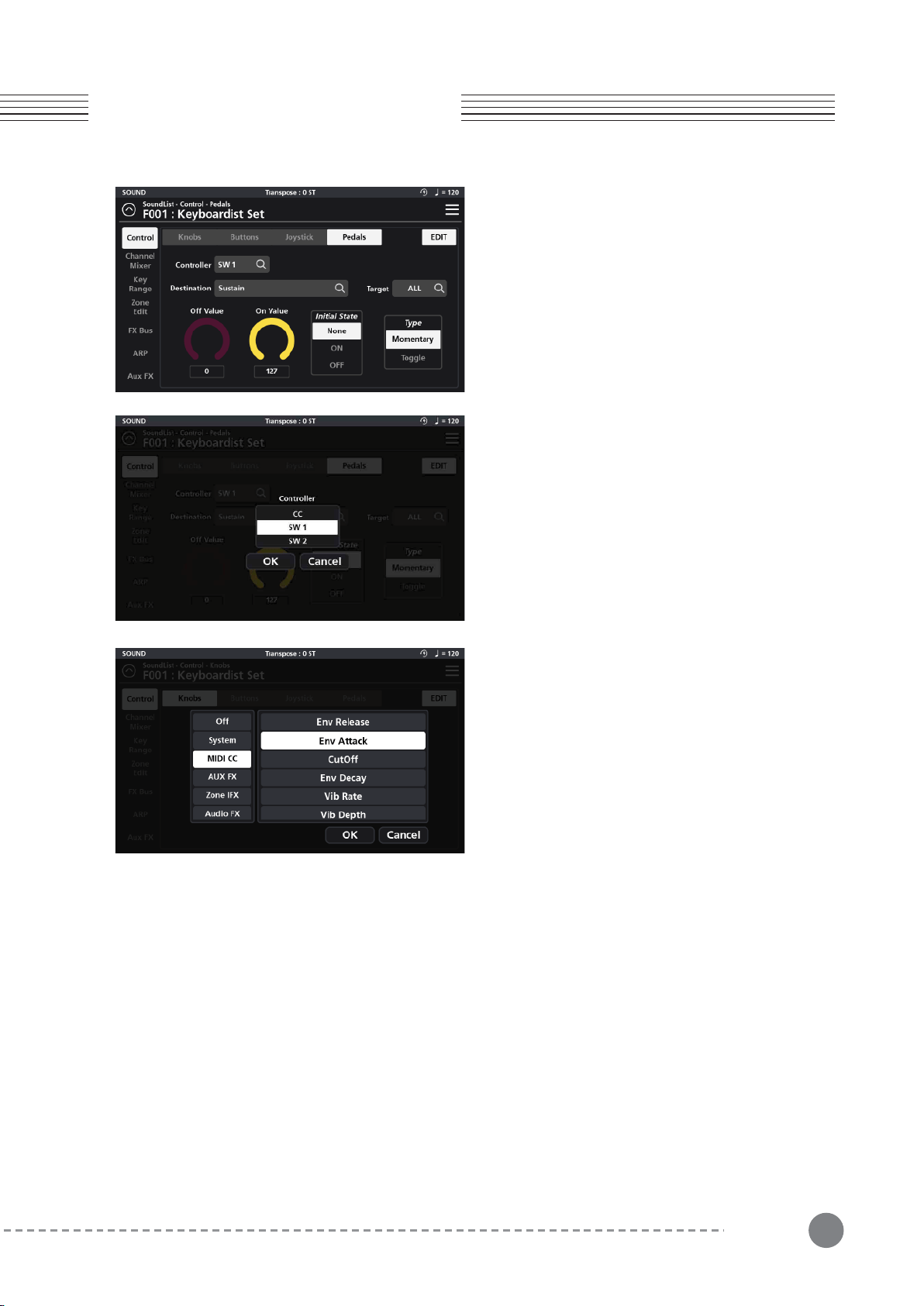
3-4-1 Assigning a Pedal Controller
Tap the Controller field and select the desired Pedal
(SW1, SW2, CC) to assign. Selecting a given pedal
displays that pedal’s parameters on screen.
3-4-2 Assigning Destinations
The Destination parameter specifies the function of the
given Pedal. Tap the Destination field to access the
function assignment page where you will be presented
with 8 Destination types to choose from: System, MIDI
CC, AUX FX, AUX EQ, Zone IFX, Audio FX, Vocal Proc
and Notes.
3-4-2-1 System
The “System” tab offers a total of 9 possible choices:
Ctrl Override: When enabled*, all controller assignments mapped within the current Sound are overridden and
take on the Global mode settings instead.
*Caution: Once enabled, the only means to disable this controller is to go to Global mode (Global 1 page) and
manually set the “Override Controller” switch back to Off.
Blink Tempo: Enables the Alpha wheel LED ring to “blink” (strobe) along with the current Global BPM tempo.
ARP Enable: Turns the arpeggiator on/off. (Note: for an arp to run, one of the 8 available arps must first be
assigned to the zone in question on the Zone Edit page - see pg 31 for more detail).
ARP Latch: This destination controls the “Arp Latch” master switch (Zone Edit / Common page). When engaged,
this allows any Arp (A-H), that has its individual “Latch” parameter (ARP / Steps menu) set to “On”, to continue
to play its pattern even after all piano keys have been released.
Chapter 3
Chapter 3. Sound Editing
The SP7 Grand has three programmable pedals: SW1,
SW2 and CC (Volume). On the “Pedals” Edit page you
can assign a Destination, change the Target, set the
Min/Max values, Initial State and pedal behavior Type.

Global BPM: This is the tempo (expressed in Beats Per Minute) applied to the entire instrument.
Pitch Bend+, Pitch Bend- : MIDI pitch bend control.
Program Change : Specify a MIDI program change (0-127) to select a given sound.Zone Activate : Enables/dis-
ables a zone.
26
Chapter 3. Sound Editing
Chapter 3
Reverb Size : Controls the size of the reverberant space.
Reverb Level : Controls the amount of reverb.
Reverb Time : Controls the length of reverb decay.
Chorus Level : Controls the amount of the chorus effect.
Chorus Feedback : Controls the level of chorus feedback.
Chorus Rate : Controls the speed of chorus modulation.
Chorus Depth : Controls the maximum detuning range of the chorus modulation.
Cho To Rev : Controls the amount of Chorus fed into the Reverb.
Delay Level : Controls the amount of delay.
Delay Time : Controls the interval of time it takes for the sound to repeat.
Delay Feedback : Controls the amount of delay feedback.
Dly To Rev : Controls the amount of Delay fed into the Reverb.
Dly To Cho : Controls the amount of Delay fed into the Chorus.
3-4-2-2 MIDI CC
The full compliment of 128 Standard MIDI CCs can be assigned by selecting from a drop down scroll list.
3-4-2-3 AUX FX
The “Aux FX” tab offers 13 possible destinations governing the AUX FX section:
EQ Low Gain : This function adjusts the low frequency range.
EQ Mid Low Gain : This function adjusts the low-mid frequency range.
EQ Mid High Gain : This function adjusts the high-mid frequency range.
EQ High Gain : This function adjusts the high frequency range.
3-4-2-4 AUX EQ
The Aux EQ tab offers adjustments covering the 4 frequency bands of the Aux EQ:
Output Volume : This function controls the volume level of the post IFX/pre Aux FX signal.
Pan : This function adjusts the left/right balance of the post IFX/pre Aux FX signal.
Reverb Send : This function controls the amount of post IFX sent to the Aux Reverb.
ChoDly Send : This function controls the amount of post IFX signal sent to the Aux Chorus and Delay.
3-4-2-5 Zone IFX (Zone Insert Effect)
The “Zone IFX” tab offers 4 possible destinations governing the IFX Mixer:
27
Chapter 3
Chapter 3. Sound Editing
3-4-2-6 Audio FX
The “Audio FX” tab offers 4 possible destinations governing the Audio Input Mixer:
3-4-2-8 Notes
The Notes tab allows you to select individual MIDI note numbers (#0-127) to trigger from the selected pedal. The
velocity is determined by the Min/Max Value (CC pedal) or Max Value (SW pedals). This function can be usefully
for triggering percussion hits and sound effects.
Lead Process On/Off : This function turns the Lead Processing section on/off.
Auto Harm On/Off : This function turns the Auto Harmony section on/off.
Auto Harm Volume : This function controls the volume level of the Auto Harmony section.
3-4-2-7 Vocal Proc
The Vocal Processor tab offers 3 possible destinations governing the Vocal Processor section:
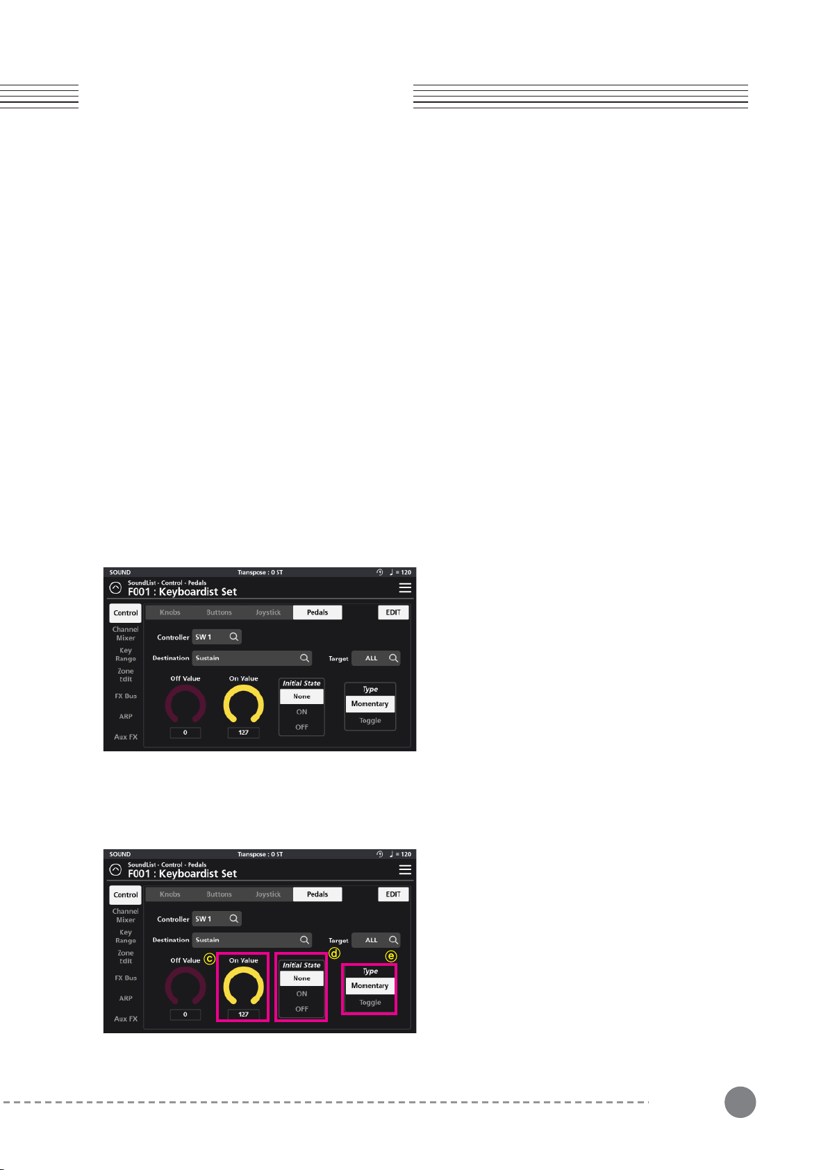
3-4-3 Assigning a Pedal Target - ⓐ
A Pedal’s operating region is determined by its Target
assignment. Depending on the chosen Destination,
Target selection options can be: None, Preset, System,
Zone1~16, Zone ALL, FX A~D, FX ALL, Input 1~2 and
Input ALL.
3-4-4 Assigning a Pedal Off Value - ⓑ
For SW pedals, the Off value is the value (0-127) sent
when the given Pedal is released.
For the CC pedal, the Off value sets its minimum
adjustable value (value range = 0-127).
3-4-5 Assigning a Pedal On Value - ⓒ
For SW pedals, the On value is the value (0-127) sent
when the given Pedal is depressed.
For the CC pedal, the On value sets its maximum
adjustable value (value range = 0-127).
Output Volume : This function controls the volume level of the post IFX/pre Aux FX signal.
Pan : This function adjusts the left/right balance of the post IFX/pre Aux FX signal.
Reverb Send : This function controls the amount of post IFX sent to the Aux Reverb.
ChoDly Send : This function controls the amount of post IFX signal sent to the Aux Chorus and Delay.
28
Chapter 4. Multi Sound Editing
Chapter 4
Chapter 4. Multi Sound Editing
In the SP7 Grand, all Sounds are actually comprised of up to 16 individual zones (multitimbral). Each zone can have
its own sound preset, key range, mix settings and unique controller assignments. By assigning a zone controller
(button, pedal or knob) to the “Zone Activate” Destination, you can conveniently mute and unmute different zones
to create multi-layered/split combination sounds on the fly.
Multi sound editing is accessed from the Channel Mixer, Key Range, and Zone Edit tabs of the Sound EDIT page.
Adjust all parameter dials by touch, alpha wheel (once selected), Increase+/Decrease- buttons, or tap the value
field to open a numeric keypad for more precise data entry.
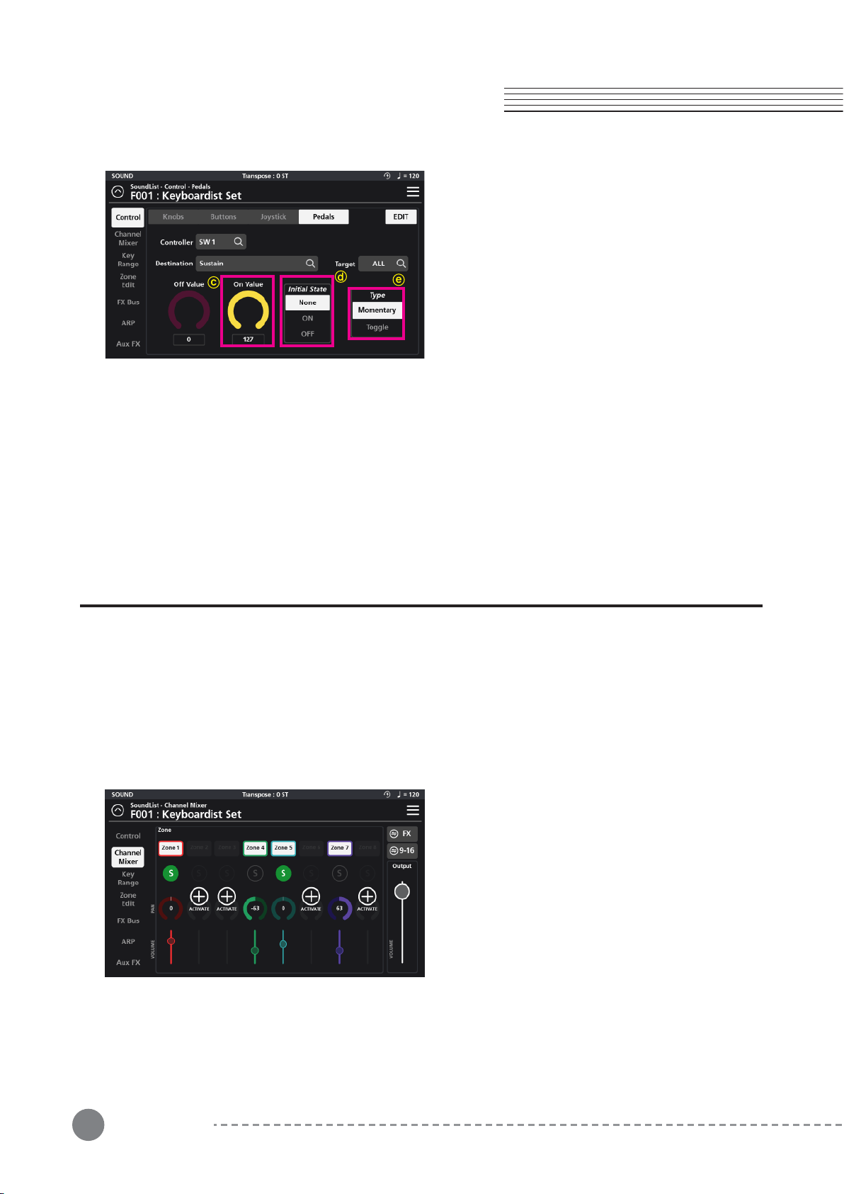
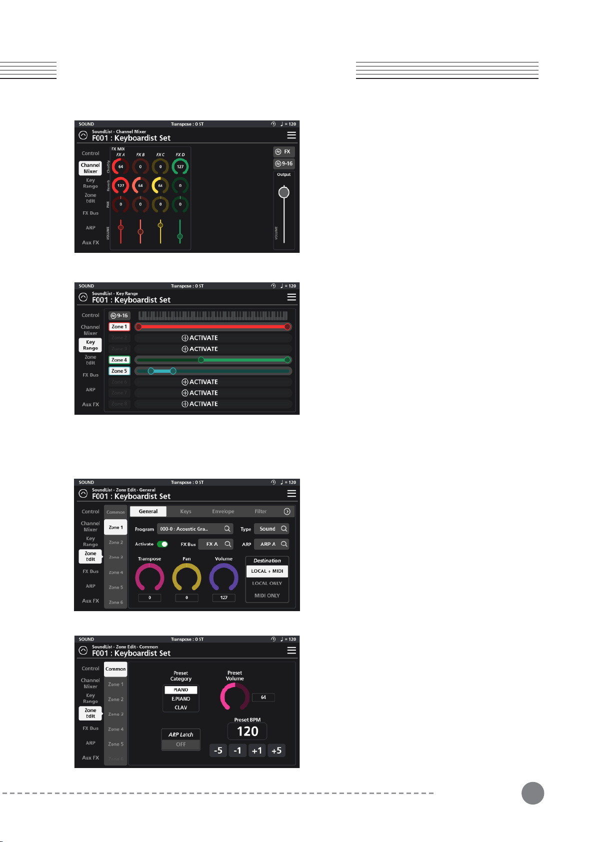
The Channel Mixer is used to adjust the mix settings of
the 16 multi zones. For easier viewing and adjustment,
the mixer is divided on screen into two banks of 8
channels, which you can toggle between by tapping the
“9-16” (1-8) button in the upper right.
Each of the 16 mixer channel strips consists of a zone
on/off status icon, solo, zone activate, pan and volume
fader.
Enable a new channel (zone) by clicking the (+) ACTI-
VATE icon. To disable a channel, tap the corresponding
numbered zone on/off status icon (at the top of the
channel strip).
Control the overall mix level using the Output volume
fader on the right.
3-4-6 Assigning a Pedal Initial State - ⓓ
The Initial State establishes a given pedal’s default
starting point when a sound is first selected. “None”
sets no initial state and, as such, will adopt the state (on
or off) of that same pedal from the previously selected
sound. A setting of On or Off specifically sets the pedal
to the corresponding On or Off value when the sound is
first selected.
3-4-7 Assigning the Pedal Type - ⓔ
Use the Type parameter to set an SW pedal behavior to Momentary or Toggle.
When Type is set to Momentary, the given SW pedal sends its “On Value” when pressed, and its “Off Value” when
released.
When Type is set to Toggle, the given SW pedal alternates between sending its “On Value” or “Off Value” each time
it is pressed. No value is sent when the pedal is released.
4-1 Channel Mixer
29
Chapter 4
Chapter 4. Multi Sound Editing
4-1-1 FX Mixer
The effects (FX) mixer conveniently displays the same
FX controls as found on the individual FX Bus Mix pages
but offers the advantage of viewing all four busses at a
glance (FX A, FX B, FX C, and FX D).
Each FX mixer channel strip contains controls for
Cho/Dly (Chorus/Delay), Reverb, Pan, and Volume.
To return to the Channel Mixer page, tap the “Zone”
button in the upper right hand corner.
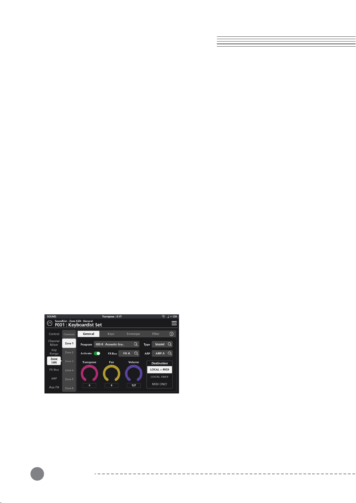
4-2 Key Range
The Key Range page allows you to define the region of the
keyboard that each zone will occupy. For easier viewing and
adjustment, the 16 possible zones are divided on screen into
two banks of 8 zones, which you can toggle between by
tapping the “9-16” (1-8) button just to the left of the graphic
piano keyboard. Enable a new zone by clicking the (+)
ACTIVATE icon. To disable a zone, tap the corresponding
numbered zone on/off status icon (to the left of each graphic
range). As needed, drag the left and right circles at the ends of
each zone to determine the area over which that zone will play.
4-3 Zone Edit
The left side of the Zone Edit page displays 16 zone
selector tabs (1-16) for accessing each zones’ individual
parameters as well as a Common tab at the top of the
list for editing parameters common to all zones.
4-3-1 Common
The settings in the Common tab consist of Preset
Category, Preset Volume, Arpeggiator (ARP) Latch
On/Off, and Preset BPM settings.
30
Chapter 4. Multi Sound Editing
Chapter 4
4-3-1-1 Preset Category
This parameter sets the category that the sound will be grouped into when you press one of the Category tabs or
buttons from the Sound mode.
4-3-1-2 Preset Volume
With this parameter you can set the default volume for the multi as a whole.
4-3-1-3 ARP Latch
A “latched” arpeggiator allows an arp pattern, once initially triggered, to continue to run without manually holding
down piano keys. The Common page “ARP Latch” function acts as a master switch, turning the arpeggiator latch
on/off for the whole multi.
Each of the eight Arps (A-H), in turn, has its own individual “Latch” switch (ARP / Steps menu) which determines
if that given Arp will be included in any latched arpeggiator activity.
Set the Arp Latch switch to On to enable latched arpeggiator activity. Set the Arp Latch switch to Off to stop all
latched arpeggiator activity.
Tip: Consider assigning “ARP Latch” as a destination to a button/pedal/knob for convenient use during performance.
4-3-1-3 Preset BPM
The Preset BPM parameter sets the master tempo (in beats per minute) for all tempo related elements in the
multi combination including arps and tempo related effects. Change the tempo value by pressing the -5, -1, +1,
+5 increment buttons or by tapping on the BPM field to access a numeric keypad and type in desired values.
4-3-2 Zone 1-16
In addition to the common parameters affecting all zones, each zone can be individually edited and further
customized by selecting the desired zone from the tabs on the left. Each zone uses the same MIDI channel as its
zone number (zone 1= channel 1, zone 2 = channel 2, etc). Zone Edit settings are grouped into 8 subpages:
General, Keys, Envelope, Filter, Vibrato, Portamento, AuxSend, and Misc (Miscellaneous).
4-3-2-1 General
The General tab is for Program selection, Type (Sound
vs Drum), Activate On/Off, FX Bus selection, Arpeggia-
tor (ARP) selection, Transpose, Pan, Volume, and
Destination.
31
Chapter 4
Chapter 4. Multi Sound Editing
4-3-2-1-2 Type
Programs in the SP7 Grand are grouped into two broad categories: Sound (non-percussion) and Drum (percus-
sion). The “Type” selector toggles between the category of Programs displayed (Sound or Drum) in the Program
selection field (above). Click on the magnifying glass icon and a pop-up window will appear allowing you to make
a selection.
4-3-2-1-3 Activate
The Activate On/Off switch enables (green) and disables (red) the selected zone.
Tip: Consider assigning “Zone Activate” as a destination to a button/pedal/knob to mute/unmute zones for
convenient use during performance.
4-3-2-1-4 FX Bus
Select the insert FX Bus (A-D) to process the zone. Disable the insert effect by selecting Bypass.
4-3-2-1-5 ARP (Arpeggiator)
Tap the ARP field to assign one of the eight available arpeggiators (A-H) to trigger the current zone. Selecting
None will disable the arpeggiator.
4-3-2-1-6 Transpose
The Transpose parameter shifts the pitches generated by the given Zone. You can transpose up or down in
semitone steps.
4-3-2-1-7 Pan
The Pan parameter sets the panning (left/right stereo placement) of each Zone.
4-3-2-1-8 Volume
The Volume parameter sets the volume of each Zone.
4-3-2-1-9 Destination
The Destination parameter controls the MIDI output routing of the selected zone. The destination can be set as
Local+MIDI (internal sound+external MIDI transmission), Local ONLY (internal sound only - no MIDI output), and
MIDI ONLY (external MIDI output only - no internal sound triggering).
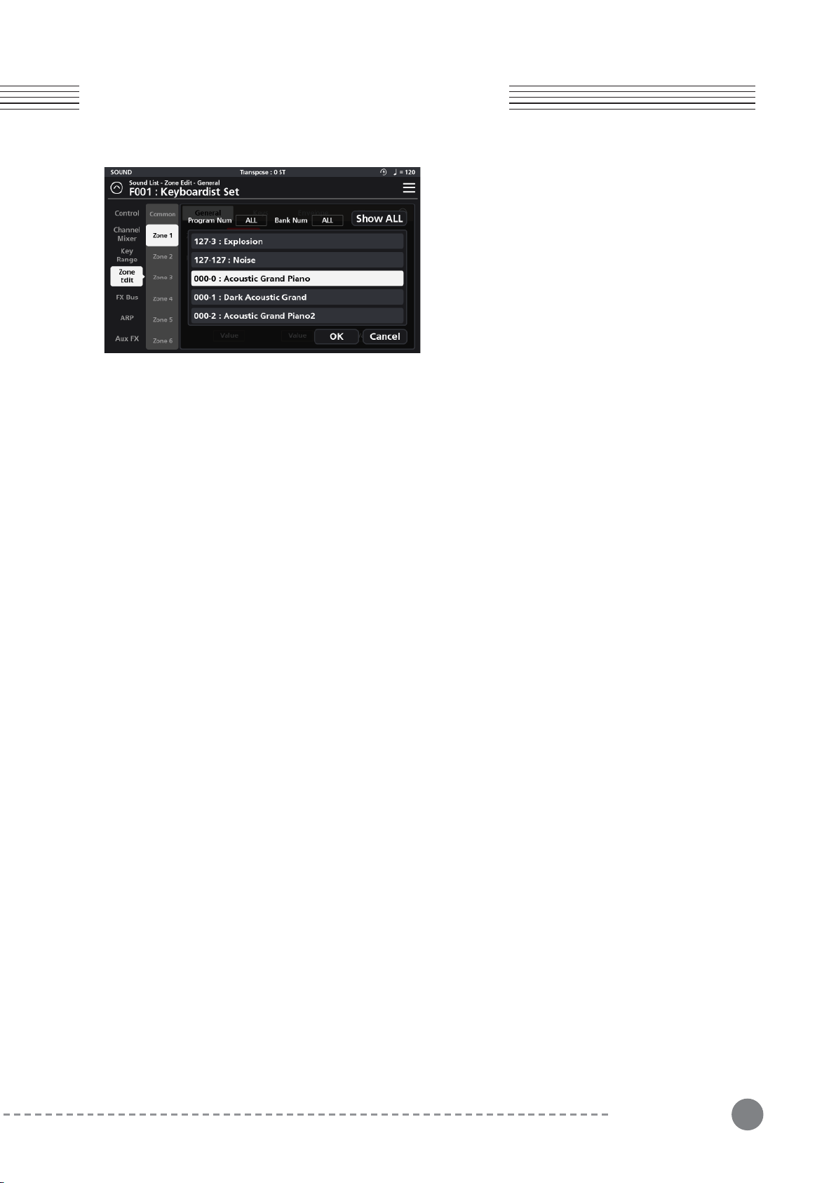
4-3-2-1-1 Program
Select the program for the current Zone. Click the magnify-
ing glass icon to display the program list. You can select the
desired program simply by scrolling through the list.
You can also filter the list by Program and/or Bank Number.
Each Program ID is formatted as XXX-Y where “XXX” =
program number and “Y” = Bank number.
Tap the “Program Num” and/or “Bank Num” field to access
a numeric keypad to apply a filtered search.
Click the “Show All” button at any time to re-display the full
list of available programs.
32
Chapter 4. Multi Sound Editing
Chapter 4
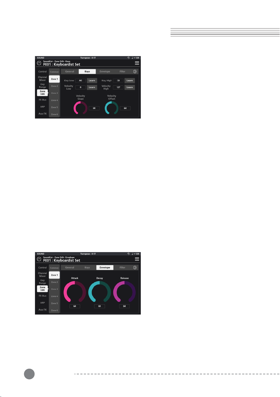
4-3-5-2 Keys
Under the Keys tab you can set both the key and
velocity ranges for the current zone.
With "Key Low” and “Key High”, you can select the
lowest and highest notes on the keyboard that the
current zone will trigger (these values mirror those on
the graphic Key Range page).
With “Velocity Low” and “Velocity High”, you can set the
lowest and highest note velocities that will trigger the
given layer.
The simplest method to change these parameters is to employ the “Learn” function associated with each.
When pressed, the “Learn” icon will light, prompting you to strike the piano keyboard to enter either key or
velocity ranges. When entering velocities, the note you strike does not matter, only the strength in which you
strike it (0-127) is captured.
4-3-2-2-2-1 Velocity Slope
The Velocity Slope parameter allows scaling of the overall dynamic range of the layer. The default value is 64
(linear). Values above 64 increasingly amplify velocities (making the output louder with less effort) while values
below 64 gradually diminish velocities (making the output quieter even with stronger velocities).
4-3-2-2-2 Velocity Offset
The Velocity Offset parameter applies a fixed amount (adding or subtracting) to the velocities performed. Values
above the default (64) create stronger/louder velocities while values below 64 create weaker/softer velocities.
4-3-2-3 Envelope
The Envelope page offers a 3-segment amplitude
envelope generator with Attack, Decay and Release
controls to help shape the sound.
33
Chapter 4
Chapter 4. Multi Sound Editing
4-3-2-3-1 Attack
Attack is the amount of time it takes for a note, when struck, to go from silence to full volume. The greater the
value the slower the attack. Smaller values equal a faster attack.
4-3-2-3-2 Decay
Decay is the amount of time it takes for a held note to transition from its maximum volume to a sustained level.
The greater the value the slower the decay. Smaller values equal a faster decay.
4-3-2-3-3 Release
Once a key is let go, Release is the the amount of time it takes for the note volume to drop from its sustained
level to silence. The greater the value the slower the release time. Smaller values equal a faster release time.
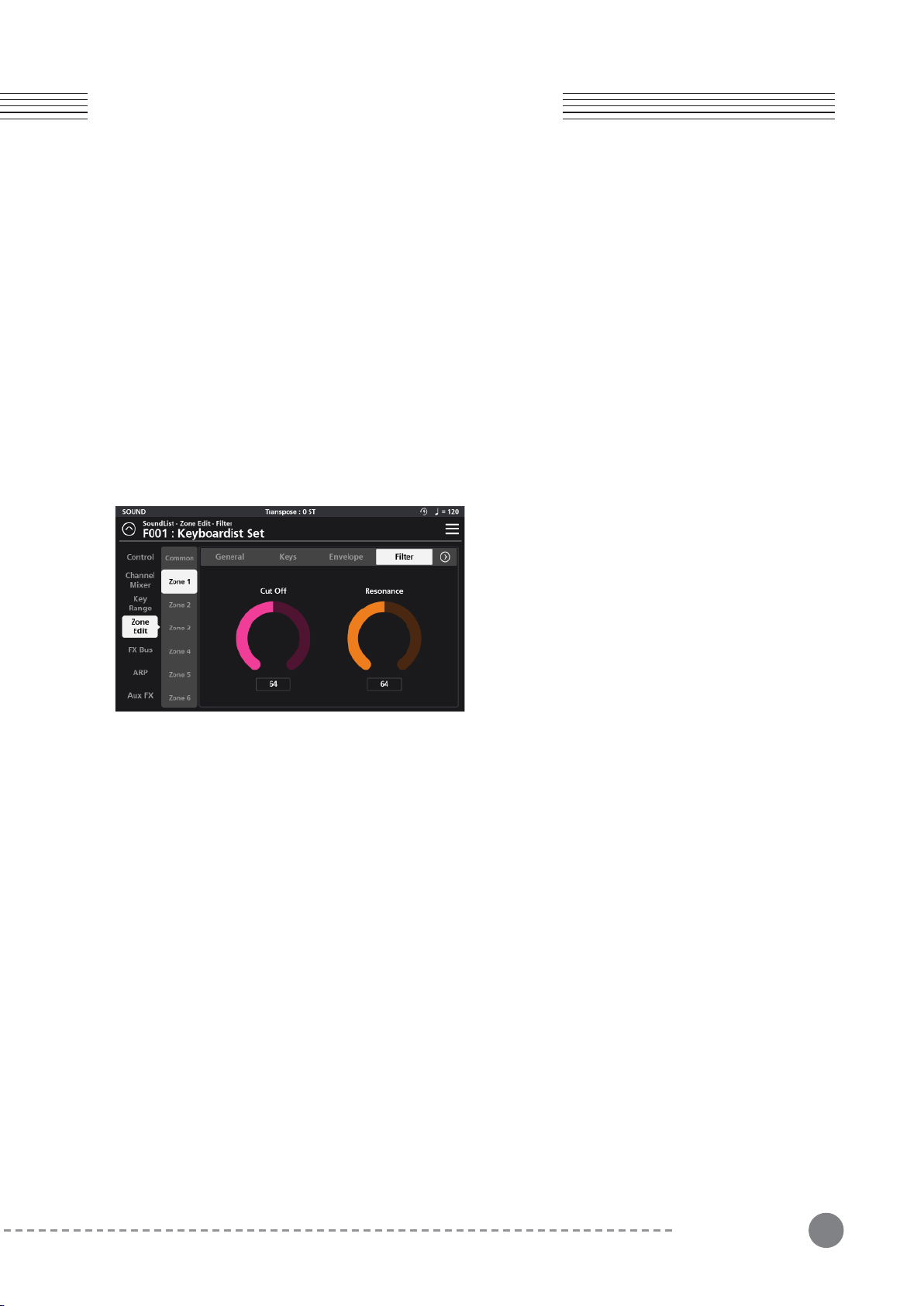
4-3-2-4-1 Cut Off
The Cut Off parameter controls the frequency above which the signal is attenuated. Higher cutoff values allow
higher frequencies to pass (be audible) and thus output a brighter sound. Lower cutoff frequencies gradually
remove more of the upper frequency spectrum and produce darker tones.
4-3-2-4-2 Resonance
The Resonance parameter controls the amount of emphasis applied at the filter cutoff frequency (as set above)
creating a distinct effect.
4-3-2-4 Filter
The Filter tab provides access to a low pass filter with
Cut Off and Resonance controls.
34
Chapter 4. Multi Sound Editing
Chapter 4
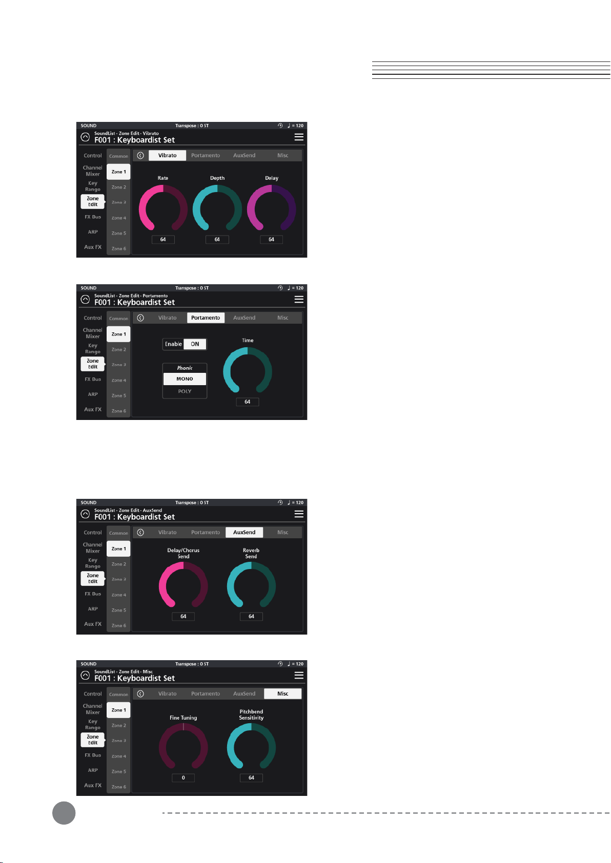
4-3-2-4-3 Vibrato
The Vibrato tab provides access to a variable low
frequency oscillator (LFO) with Rate, Depth, and Delay
controls that effect the pitch of the sound.
The Rate dial sets the speed of the vibrato.
The Depth dial controls the amount of pitch variation.
The Delay dial lets you set the time interval between
the start of the sound and the start of the vibrato effect.
4-3-2-4-4 Portamento
With Portamento enabled, notes played in a program
can glide from the pitch of the previously played note to
the pitch of the currently played note.
The Portamento tab provides parameters to control the
behavior of the portamento effect.
Tap the “Enable” On/Off switch to engage the
effect.Use the “Phonic” parameter to select between
Monophonic (Mono) and Polyphonic (Poly) performance.
Mono plays only one note at a time.
Poly permits polyphonic playing and note gliding.
The “Time” parameter determines the time it takes to glide between notes. Lower values create faster transitions
where higher values create slower ones.
4-3-2-4-5 AuxSend
The AuxSends tab provides effects send controls for
the Delay/Chorus and Reverb sections of the Aux FX
4-3-2-4-6 Misc
On the Miscellaneous (Misc) page you will find adjust-
ments for Fine Tuning and Pitch Bend Sensitivity.
The Fine Tuning dial allows you to tune the program +/-
100 cents (+/- 1 semitone). The Pitch Bend Sensitivity
controls the range of operation of any Pitch Bend activity
(default controller is the x-axis of the joystick). Pitch bend
can be adjusted +/- 24 semitones (+/- 2 octaves).
35
Chapter 4
Chapter 4. Multi Sound Editing
4-4 ARP (Arpeggiator)
The arpeggiator is a rhythmic/melodic pattern generator that is fed by notes played on the keyboard. The SP7
Grand has 8 independent arpeggiators (A to H) and employs a hybrid design blending traditional arpeggiator
functions along with a step-based sequencer. The settings that governing all Arp operations are found on the two
Arp tabs: General and Steps.
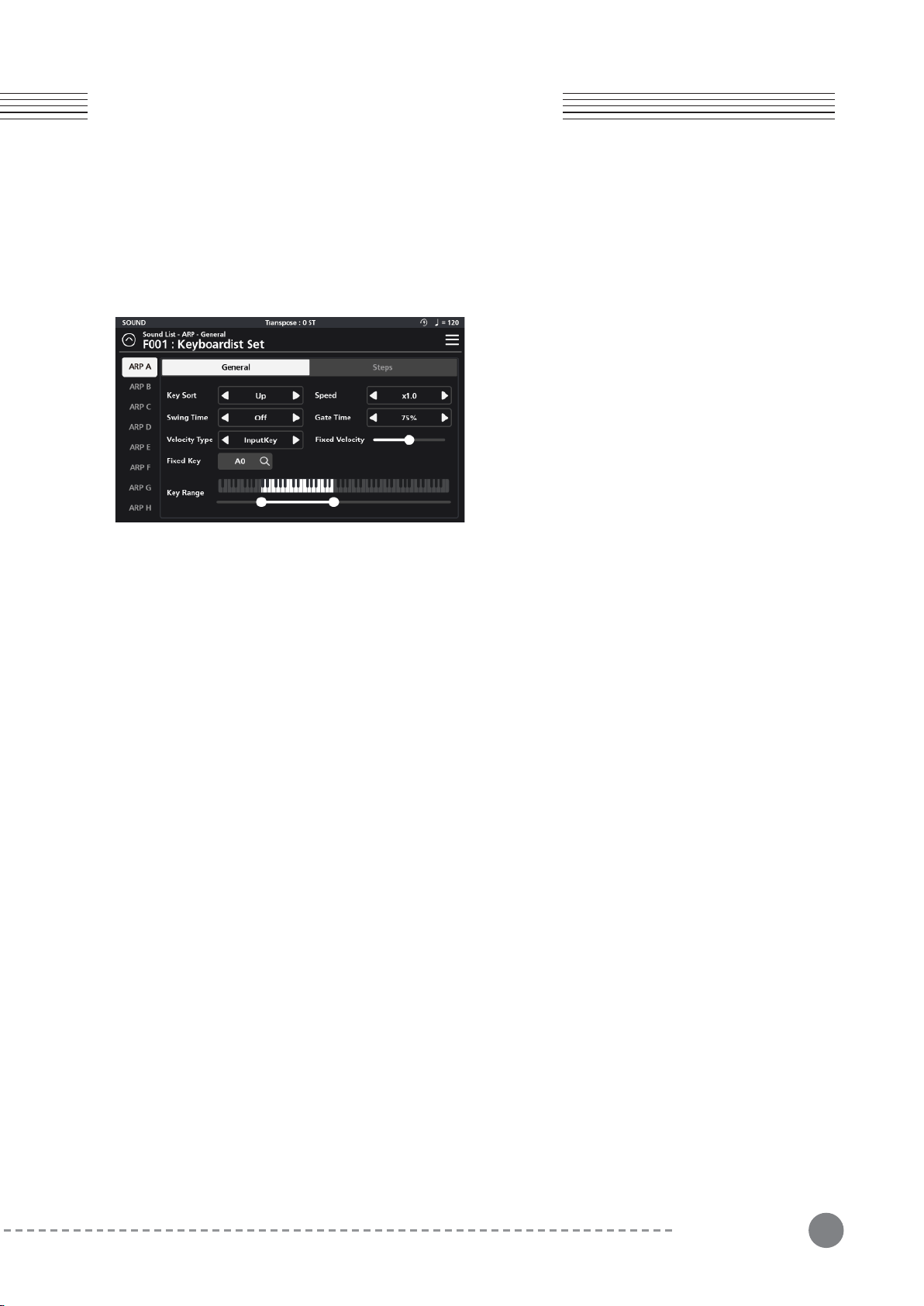
4-4-1-1 Key Sort
Key Sort determines the note order in which the arpeggiator pattern will run.
The arpeggiator can run its patterns following one of 3 methods: as played (None), upwards (Up) or downwards (Down).
4-4-1-2 Speed
The arpeggiator plays at the root tempo specified on the Zone Edit Common page.
The Speed parameter provides 3 options that allow you to further scale the speed of the arp: x1 (no change) x0.5
(half-time) or x2.0 (double-time).
For example if the Common page tempo is set at 100 and you select x0.5 the resultant playback speed would be
50. Choose x2.0 and the resultant tempo would be 200.
4-4-1-3 Swing Time
Swing Time is a function that creates rhythms with a triplet feel by modifying the timing of the rhythmic intervals.
The setting choices are: OFF, 25%, 50% and 75%. The higher the setting, the stronger the swing feel.
4-4-1-4 Gate Time
Gate Time is a function that modifies the duration of the notes played by the arpeggiator.
Value setting choices are: 90%, 75%, 50%, and 25%. Higher percentages create more connected (legato-like)
notes where smaller percentages creates more staccato-like results.
4-4-1-5 Velocity Type
The Velocity Type parameter controls the strength of the notes played by the arpeggiator. When set to “InputKey”
the velocity sounded by the arpeggiator is as played. When set to “Fixed”, each note sounded by the arpeggiator
has the same velocity and that velocity is determined by the adjacent “Fixed Velocity” slider. With the value of “
Step” assigned, the velocity of each note in the pattern is determined by the individual steps of the step sequenc-
er (Steps tab).
4-4-1 General
The General tab displays settings for Key Sort, Speed,
Swing Time, Gate Time, Velocity Type, Fixed Velocity,
Fixed Key, and Key Range.
36
Chapter 4. Multi Sound Editing
Chapter 4
4-4-1-6 Fixed Velocity
When the Velocity Type (above) is set to Fixed, the Fixed Velocity slider determines the uniform velocity of all
notes in the pattern. Moving the slider to the right increases the intensity, while moving it to the left, decreases it.
4-4-1-7 Fixed Key
The Fixed Key field allows you to specify a single note pitch (A0-C8) that will trigger for any pattern step (Steps
tab) whose “Key” parameter is set to a value of “Fixed”.
4-4-1-8 Key Range
The Key Range parameter determines the range of notes played by the arpeggiator. Set the lowest and highest
notes by dragging the left and right set points below the onscreen piano graphic.
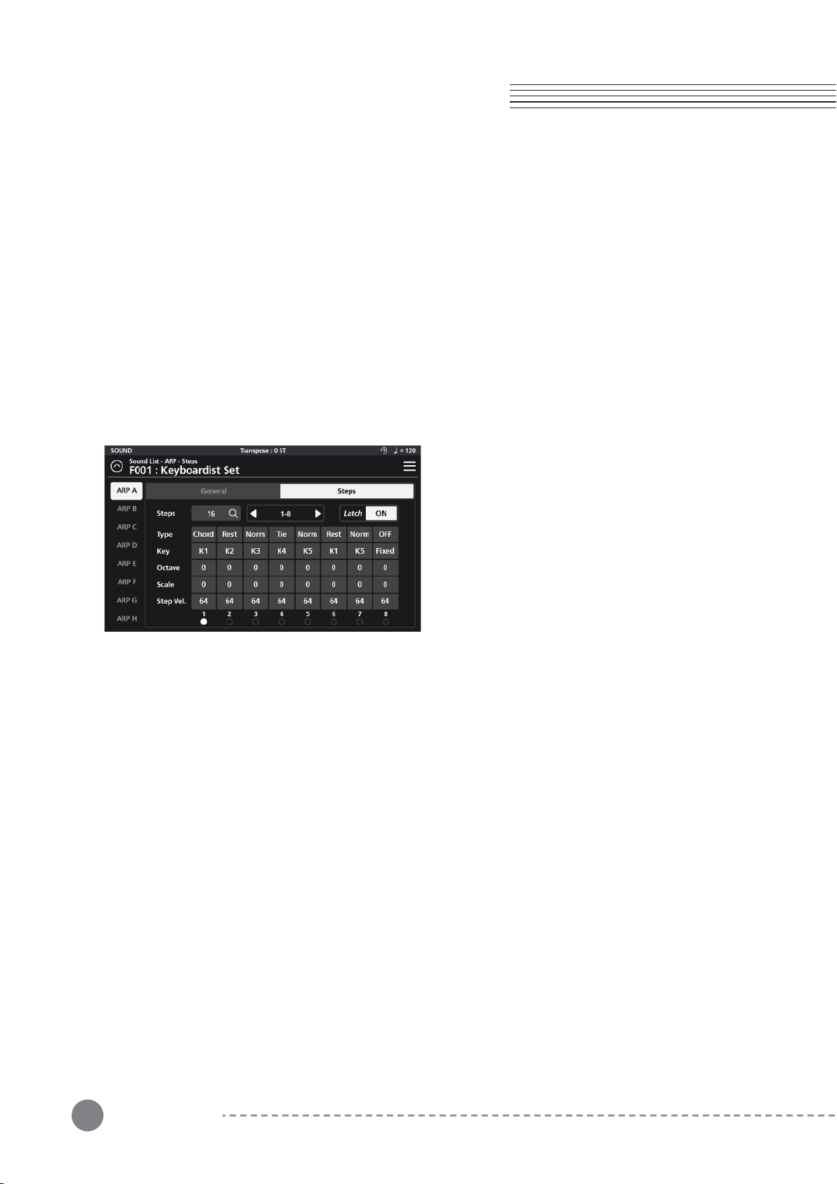
4-4-2-1 Steps
Arpeggiator patterns support up to 32 individual events (steps). The “Steps” parameter allows you to specify how
many steps the pattern will contain (1-32).
Note, the grid only displays up to 8 steps at a time, as such you choose which group of 8 steps you wish to
view/edit at any given moment. The selector field to the right of the “Steps” parameter allows you to choose
which group of 8 steps to view (1-8, 9-16, 17-24 or 25-32).
4-4-2-2 Latch
This is an on/off switch that activates the individual arpeggiator latch function. (Note: the Zone Edit/Common “
ARP Latch” master switch must be ‘On’ for any Arp (A-H) in the multi to run).
When Latch is engaged, this allows the given arpeggiator to continue to play its pattern even after all piano keys
have been released.
The parameters of the step-sequencer grid discussed below, define the behavior of each step of the current
arpeggiator pattern.
4-4-2-3 Type
The Type parameter allows you to choose the type of performance for the designated step.
There are 5 available types: Norm, Rest, Tie, Chord.
4-4-2 Steps
On the Steps tab you will find a step-sequencer grid
that forms the basis of the arpeggiator pattern to be
triggered. The Steps tab displays settings for Steps,
Latch, Type, Key, Octave, Pitch and Step Velocity.

37
4-4-2-4 Key
The Key parameter assigns the notes you play to the individual pattern steps. Up to 5 notes are possible, labeled
K1 to K5. By assigning K1-K5 to the various steps, you determine which performed note(s) is triggered at each
step in the pattern.
Select “Fixed” to trigger the note selected as the “Fixed Key” (General tab).
4-4-2-5 Octave
The Octave parameter sets the octave of the note of the specified step (+/- 3 oct).
4-4-2-6 Pitch
The Pitch parameter transposes the pitch of the note of the specified step (+/- 12 semitones).
4-4-2-7 Step Vel. (Step Velocity)
When the Velocity Type parameter (General tab) is set to “Step”, the Step Vel. Value becomes the note velocity of
the specified step.
4-4-2-8 Step Indicator
The Step Indicator is a visual aid located at the bottom of the step grid. When the arpeggiator is running, a white
dot moves along in time, advancing with each pattern step, making for easier editing.
Norm : Plays a single note.
Rest : Adds a musical rest (silence) at the specified step.
Tie : Creates a musical tie in relation to the previous note in the pattern. A new note attack is not struck unless
the pitch itself changes.
Chord : Plays a chord instead of playing a single note for that specified step.
OFF : Turns off the specified step.
Chapter 4
Chapter 4. Multi Sound Editing
38
Chapter 5. FX Editing
Chapter 5
Chapter 5. FX Editing
5-1 FX Bus
The effect bus (FX Bus) menu houses the parameter
controls for the four insert effect busses (FX A, FX B, FX C,
and FX D). Each effects bus is comprised of 5 sections;
Dynamics(Dyn), Parametric EQ (P.EQ), Modulation/Wah-
Wah (Mod/Wah), Delay/Tremolo (Dly/Trm), and Mix.
Adjust all parameter dials by touch, alpha wheel (once
selected), Increase+/Decrease- buttons, or tap the value
field to open a numeric keypad for more precise data entry.
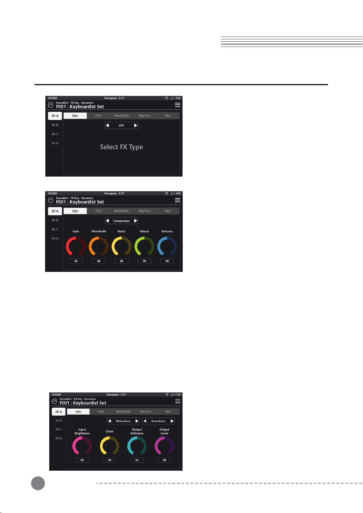
5-1-1 Dyn (Dynamic)
The Dynamics section consists of three different
effects processes: Compression, Distortion, and Bit
Crusher.
5-1-1-2 Distortion
There are 6 distortion character types available: Over-
drive, Distortion, Fuzz, Fuzz2, Tube, and Asymmetrical.
With each type, you have fine-tune adjustments for
Input and Output Brightness, Drive and Output Level.
Input Brightness - A low pass filter allowing you to
color the signal feeding into the distortion circuit.
5-1-1-1 Compressor
The compressor circuit offers controls for Gain, Threshold, Ratio, Attack, and Release.
Gain - Amplifies the post-compression signal (aka make-up gain).
Threshold - Sets the level at which compression begins. Higher values lead to less compression whereas lower
values compress more of the signal.
Ratio - Determines how much gain reduction the compressor applies when the signal passes above the set thresh-
old level. Higher values equal more gain reduction.
Attack - Controls the time it takes for compression to begin once
the signal level surpasses the threshold. Lower values equal faster attack times (reducing attack transients) where
larger values equal slower attack times (allowing more of the attack transients to pass through).
Release - Controls how long it will take for the compression to relax once the signal has fallen below the threshold.
39
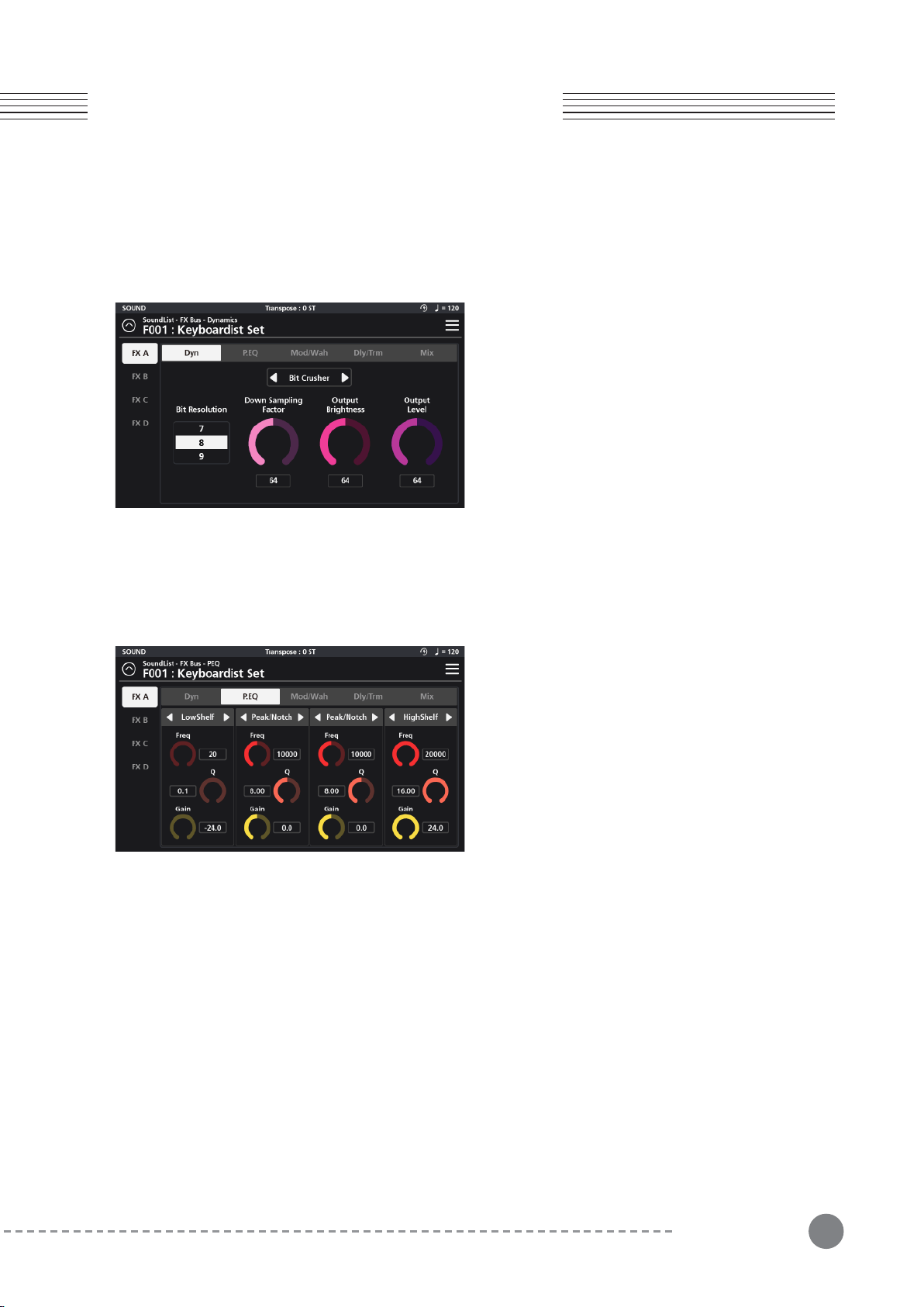
5-1-1-3 Bit Crusher
The Bit Crusher section is a digital degradation distortion.
It intentionally introduces quantization noise and aliasing
artifacts, allowing you to adjust the Bit Resolution,
Down Sampling Factor, Output Brightness, and Output
Level.
Bit Resolution - Allows you to set the bit depth of the signal,
ranging from 24 bits down to 1 bit. Lower values increase
5-1-2 P.EQ (Parametric Equalizer)
The EQ section is a 4-band parametric. With each band
you can choose between 7 EQ types using the selector
tabs at the top of each band: a LPF 6dB, LPF 12dB,
LowShelf, Peak/Notch, HighShelf, HPF 6dB and
HPF12dB.
For each EQ type (excluding the LPF/HPF) you can set
the frequency (Freq), quality factor (Q), and gain (Gain).
Chapter 5
Chapter 5. FX Editing
LPF 6dB and LPF 12dB - Low pass filters that reduce high frequencies above the set frequency. 6dB and 12dB
slopes are available. The higher the slope, the steeper the cut off.
LowShelf - A low shelving filter that cuts or boosts frequencies below the set frequency.
Peak/Notch - A fully parametric filter with controls for specifying the center frequency (Freq), width of the
frequency band around the center frequency (Q) and amount of boost/cut (gain) for the specified area..
HighShelf - A high shelving filter that cuts or boosts frequencies above the set frequency.
HPF 6dB, HPF 12dB - High pass filters that reduce low frequencies below the set frequency. 6dB and 12dB
slopes are available. The higher the slope, the steeper the cut off.
5-1-3 Mod/Wah (Modulation, Wah)
The Mod/Wah section offers separate modulation and “wah-wah” effects. Only one of these effects can be used at
a time, so you must designate one or the other by way of the selector tab at the top center of the parameter area.
Modulation
The Modulation effect consists of 5 options: Rotary, Chorus, Vibrato, Flanger, and Phaser. These are chosen using
the selector tab to the right of the main Modulation/Wah selector.
Output Brightness - A low pass filter allowing you to process the post distortion signal.
Drive - Adjusts the input gain feeding into the distortion circuit. Increasing the drive will increase the given
distortion effect.
Output Level - Controls the overall level of the post-distortion effects section.
Drive - Adjusts the input gain feeding into the distortion circuit. Increasing the drive will increase the given
distortion effect Output Level - Controls the overall level of the post-distortion effects section.
the number of sampling errors, generating more distortion.
Down Sampling Factor - Reduces the sample rate, introducing aliasing. A value of 1 has no effect on the signal. Higher
values increase the artifacts.
Output Brightness - Is a low pass filter allowing you to color the post it-crushed signal.
Output Level - Controls the overall level of the post bit-crushed effects section.
40
Chapter 5. FX Editing
Chapter 5
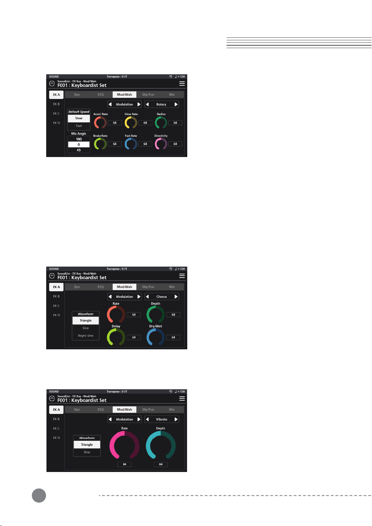
5-1-3-1 Rotary
Rotary reproduces the effect of a rotating speaker and
is commonly paired with classic tonewheel organ
sounds. There are 8 detailed settings:
Default Speed - Select the default rotation speed of the
speaker, Slow or Fast.
Mic Angle - Select the angle of the microphone relative
to the front of the rotating speaker. It can be set to 45
degrees, 90 degrees, or 135 degrees.
5-1-3-2 Chorus
The Chorus effect provides 5 parameter settings:
Waveform - Select from 3 waveforms shapes: Triangle,
Sine, and Async sine.
Rate - Determines the frequency of signal modulation.
Higher values equal faster rates.
Depth - Sets the depth of the pitch modulation. Higher
values equal wider pitch variations.
Delay - Adds delay in front of the modulated signal.
5-1-3-3 Vibrato
The Vibrato effect provides 3 parameter settings:
Waveform - Select from 2 waveforms shapes: Triangle
and Sine.
Rate - Determines the rate of vibrato. Higher values
equal faster modulation rates.
Depth - Sets the depth of the pitch modulation. Higher
values equal wider pitch variations.
Accel.Rate - The Acceleration Rate equals the time it takes for the speaker to transition from its Slow to Fast
Rate settings.
Brake Rate - The Brake Rate equals the time it takes for the speaker to transition from its Fast to Slow Rate
settings.
Slow Rate - The Slow Rate defines the rate of rotation for the speaker's Slow rotation speed. Lower values spin
the speaker more slowly. Higher values equate to a faster rotation.
Fast Rate - The Fast Rate defines the rate of rotation for the speaker's Fast rotation speed. Lower values spin
the speaker more slowly. Higher values equate to a faster rotation.
Radius- Radius sets the effective sizes of the rotating speakers. Lower values equal a smaller size.
Directivity - Directivity a function related to the dispersion of the horn. Lower values produce a narrower field
where higher values generate and increasingly wider and more pronounced doppler effect.
Higher values equal longer delay line times and thus phase variations.
Dry/Wet - Determines the balance between unaffected (dry) and effected (wet) signals. Higher values equal a
more effected signal.
41
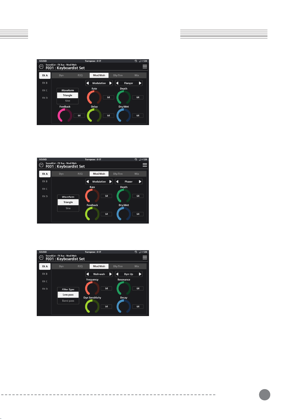
5-1-3-4 Flanger
The Flanger effect provides 6 parameter settings:
Waveform - Select from 2 waveforms shapes: Triangle
and Sine.
Rate - Determines the frequency of the LFO modula-
tion. Higher values equal faster modulation rates.
Depth - Sets the range of delay time modulation.
Higher values equal deeper comb filtering variations.
Feedback - Controls the amount of effected signal fed
back into the input to intensify the flanging effect.
5-1-3-5 Phaser
The Phaser effect provides 5 parameter settings:
Waveform - Select from 2 waveforms shapes: Triangle
and Sine.
Rate - Determines the frequency of signal modulation.
Higher values equal faster rates.
Depth - Sets the range of peaks and notches created in
the modulated signal.
Feedback - Controls the amount of effected signal fed
5-1-3-6 Wah-Wah
There are 4 types of “Wah-Wah” effect available: Dynamic
Up (Dyn Up), Dynamic Down (Dyn Down), Dynamic Up
Sharp (DynUp Sharp), and Low Frequency Oscillator (LFO).
Dynamic Up (Dyn Up) - This flavor of wah-wah increasingly
opens the filter with higher (harder) velocity playing.
Dynamic Down (Dyn Down) - ‘Dyn Up’ behaves in reverse
of ‘Dyn Up’ and increasingly opens the filter with softer
(lighter) velocity playing. Harder playing increasingly closes
the filter.
Chapter 5
Chapter 5. FX Editing
Delay - Adds delay in front of the modulated signal. Higher values equal longer delay line times and thus phase
variations.
Dry/Wet - Determines the balance between unaffected (dry) and effected (wet) signals. Higher values equal a
more effected signal.
back into the input to intensify the phasing effect.
Dry/Wet - Determines the balance between unaffected (dry) and effected (wet) signals. Higher values equal a
more effected signal.
Dynamic Up Sharp (Dyn Up Sharp) - This is similar to ‘Dyn Up’ but with a sharper resonant response.
Low Frequency Oscillator (LFO) - The LFO option creates a tempo-sync’ed ‘auto-wah’ effect.
The editable wah-wah parameters are: Filter Type, Frequency, Resonance, Dyn Sensitivity (Dyn options only), Decay (Dyn
options only), LFO Rate (LFO option only) and LFO Depth (LFO option only).
Filter Type - Select from Low Pass and Band Pass options. The ‘low pass’ filters out higher frequencies whereas the ‘band
pass’ allows frequencies within a certain range to pass and rejects (attenuates) frequencies above and below that range.
Frequency - Sets the reference frequency of the above filter. For the Low Pass option this sets the frequency above
which sound get attenuated. For the Band Pass, this defines the center of the frequency region allowed to pass through
the filter.
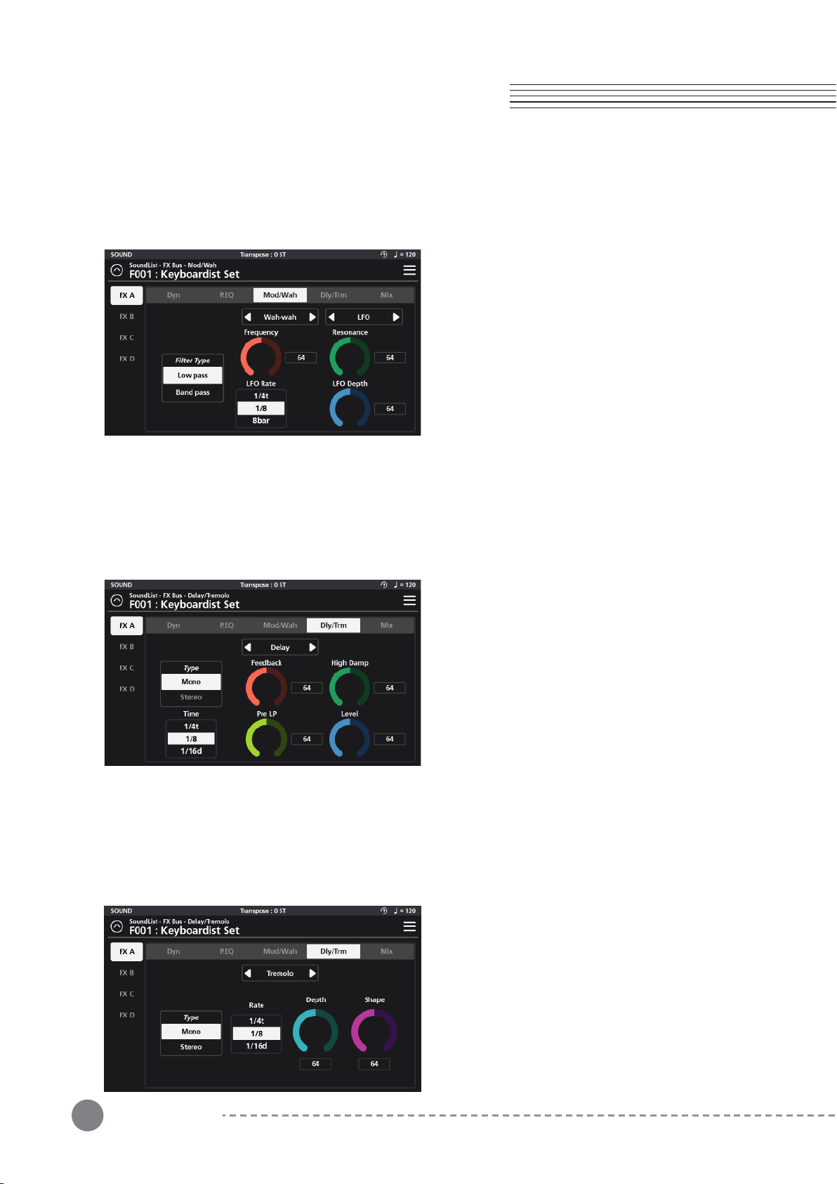
42
Chapter 5. FX Editing
Chapter 5
Resonance - This adds emphasis to the filter cut-off frequencies.
Dyn Sensitivity (Dyn options only) - Determines the range that the filter cut-off increases/decreases due to note velocity.
Higher values create a more pronounced wah-wah effect.
Decay (Dyn options only) - Determines the speed of the wah-wah envelope decay. Lower values create faster/snappier
filter decay times whereas higher values create a slower/smoother response.
LFO Rate (LFO option only) - With the “LFO” wah-wah
option selected, the “Dyn Sensitivity” dial is replaced with an
LFO Rate parameter. Instead of velocity triggering the
wah-wah effect, a low frequency oscillator (LFO) controls a
sustained modulation of the filter, creating an auto-wah
effect which is time sync’d to the value set for the LFO Rate
parameter. Available values are: 8 bar, 4 bar, 2 bar, 1 bar, 2d,
1/1t, 1/2, 1/4d, 1/2t, 1/4, 1/8d, 1/4t, 1/8. (Note: “d” = dotted
values; “t” = triplet values). All rates are relative to the Preset
BPM tempo (as set on the Zone Edit / Common page).
LFO Depth - With the “LFO” wah-wah option selected, the “Decay” dial is replaced with an LFO Depth parameter which
controls the range of filter modulation. Lower values create a subtler wah-wah effect whereas higher values create a
more pronounced effect.
5-1-4 Dly/Trm (Delay/Tremolo)
The Delay/Tremolo section offers separate delay and tremolo effects. Only one of these effects can be used at a
time, so you must designate one or the other by way of the selector tab at the top center of the parameter area.
5-1-4-1 Delay
The Delay effect provides 5 parameter settings: Type,
Time, Feedback, High Damp, Pre LP and Level.
Type - Two types of delay are available: Mono and Stereo.
Mono produces a mono-centered delay signal whereas
Stereo produces a L/R “ping-pong” style delay.
Time - Sets the “delay time” based on note values: 1/2,
1/4d, 1/2t, 1/4, 1/8d, 1/4t, 1/8, 1/16d. 1/8t, 1/16, 1/32d,
1/16t, 1/32, 1/64d, 1/32t, 1/64 (Note: “d” = dotted values;
“t” = triplet values). All values are relative to the Preset
BPM tempo (as set on the Zone Edit / Common page).
Feedback - Set the amount of delayed signal that is routed back to the input. Set to the lowest possible value to
generate a single echo. Set to the max value to endlessly repeat the signal.
High Damp - A lowpass filter placed after the delay line can be used to attenuate and color the high frequencies of the
delayed signal.
Pre LP - A lowpass filter placed in front of the feedback loop can be used to attenuate the high frequencies of the
signal. Lower values produce progressively darker echoes.
Level - Adjusts the volume level of the delayed signal.
5-1-4-2 Tremolo
The Tremolo effect provides 4 parameter settings:
Type, Rate, Depth and Shape.
Type - Two types of tremolo behavior are available:
Mono and Stereo. Mono produces a mono-centered
effect whereas Stereo produces a L/R “ping-pong”
style image.
Rate - Sets the tremolo speed based on note values:
1/4, 1/8d, 1/4t, 1/8, 1/16d. 1/8t, 1/16, 1/32d, 1/16t,
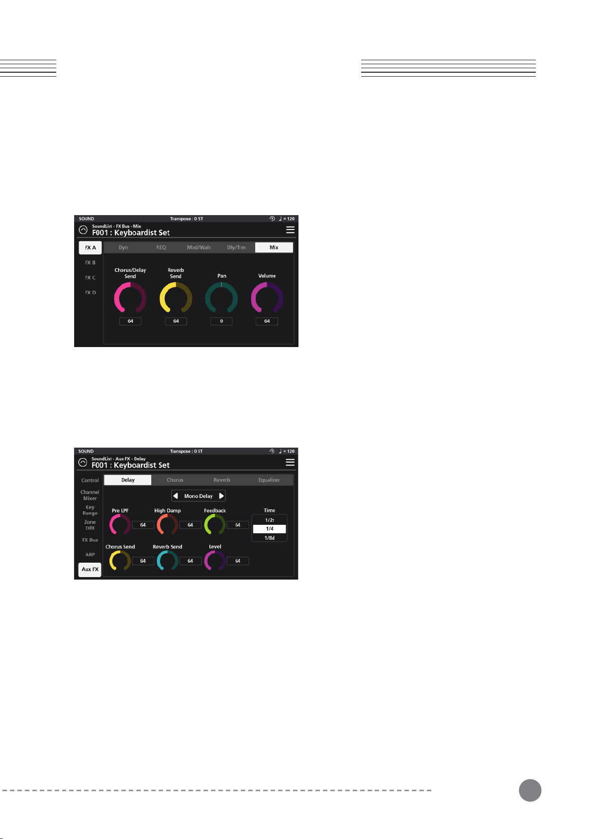
43
Chapter 5
Chapter 5. FX Editing
1/32 (Note: “d” = dotted values; “t” = triplet values). All values are relative to the Preset BPM tempo (as set on
the Zone Edit / Common page).
Depth - Controls the range of amplitude modulation. Lower values equal less change; higher values equal larger
swings in volume.
Shape - Controls the curvature of the modulation waveform. Lower values generate smoother/subtler (sine
wave) shapes where as higher values have a sharper, more abrupt character (square wave).
5-1-5 Mix
Mix is the final tab of the FX Bus and last process in the
chain. The Mix settings govern the post FX Bus (pre Aux
FX) sends for the aux Chorus/Delay and aux Reverb as well
as Pan and Volume settings.
Chorus/Delay - This controls the amount of post FX Bus
signal sent to the aux Chorus/Delay.
Reverb - This controls the amount of post FX Bus signal
sent to the aux Reverb.
Pan - Balance the post FX Bus signal left to right in the
stereo field.
Volume - This controls the output level of the post FX Bus
chain.
5-2-1 Delay
The Delay tab consists of a Mono/Stereo selector, Pre LPF,
High Damp, Feedback, Time, Chorus Send, Reverb Send,
and Level parameters.
Mono/Stereo Selector - Use the selector tab at the top
center of the screen to configure the delay as either mono,
stereo or off. “Mono Delay” produces a mono-centered
delay signal whereas “Stereo Delay” produces a L/R “
ping-pong” style delay.
5-2 AUX FX
The SP7 Grand features a 4 part Aux FX section which is comprised of a separate Delay, Chorus, Reverb, and
Equalizer. Adjust all parameter dials by touch, alpha wheel (once selected), Increase+/Decrease- buttons, or tap the
value field to open a numeric keypad for more precise data entry.
Pre LPF - A lowpass filter placed in front of the feedback loop can be used to attenuate the high frequencies of the
signal. Lower values produce progressively darker echoes.
High Damp - A lowpass filter placed after the delay line can be used to attenuate and color the high frequencies of the
delayed signal.
Feedback - Set the amount of delayed signal that is routed back to the input. Set to the lowest possible value to
generate a single echo. Set to the max value to endlessly repeat the signal.
Time - Sets the “delay time” based on note values: 1/2, 1/4d, 1/2t, 1/4, 1/8d, 1/4t, 1/8, 1/16d. 1/8t, 1/16, 1/32d, 1/16t,
1/32, 1/64d, 1/32t, 1/64 (Note: “d” = dotted values; “t” = triplet values). All values are relative to the Preset BPM tempo
(as set on the Zone Edit / Common page).
Chorus Send - This controls the amount of delayed signal sent to the Chorus effect section.
Reverb Send - This controls the amount of the delayed signal sent to the Reverb effect section.
Level - Adjusts the volume level of the delayed signal.
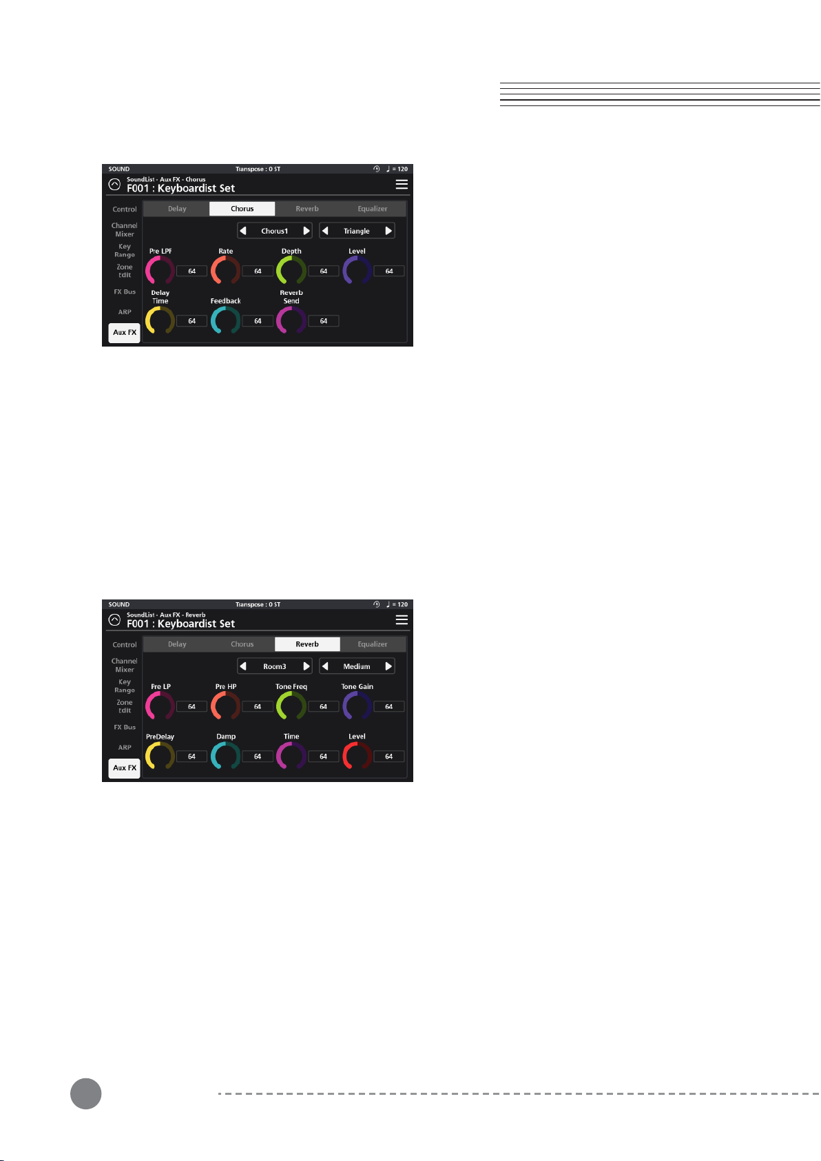
44
Chapter 5. FX Editing
Chapter 5
5-2-2 Chorus
The Chorus tab consists of a Chorus type selector,
Waveform selector, Pre LPF, Rate, Depth, Delay Time,
Feedback, Reverb Send and Level controls.
Chorus Type Selector - There are various character types
of Chorus available: Chorus 1, 2, 3, 4, Feedback Chorus (FB
Chorus), Flanger, Short Delay and Feedback Delay (FB
Delay).
5-2-3 Reverb
he Reverb tab consists of Reverb Type selector, Size
selector, Pre LP, Pre HP, Tone Gain, Pre Delay, Damp,
Time and Level controls.
Reverb Type Selector - There are various types of reverbs
available: Room 1, 2, 3, Plate, Hall 1, and Hall 2.
Reverb Size Selector - There are 3 reverb sizes available:
Small, Medium, and Large.
Waveform Selector - Select from 3 waveforms shapes: Triangle, Sine and Async Sine.
Pre LPF - A lowpass filter placed in front of the feedback loop can be used to attenuate the high frequencies of the
signal. Lower values produce progressively darker tones.
Rate - Determines the frequency of signal modulation. Higher values equal faster rates.
Depth - Sets the depth of the pitch modulation. Higher values equal wider pitch variations.
Delay Time - Adds delay in front of the modulated signal. Higher values equal longer delay line times and can color the
chorusing effect.
Feedback - Controls the amount of effected signal fed back into the input to intensify the chorusing effect.
Reverb Send - ontrols the amount of chorus signal sent to the Reverb effect section.
Level - Adjusts the volume level of the chorus effect.
Pre Low Pass (Pre LP) - A lowpass filter applied to the signal feeding the reverb. Lower values produce progres-
sively darker colors by attenuating the high frequencies.
Pre High Pass (Pre HP) - A high pass filter applied to the signal feeding the reverb. Higher values progressively
attenuate bass frequencies.
Tone Freq. - Set the frequency for a high shelving filter that boosts reverb frequencies above the designated
point.
Tone Gain - Determines the amount of gain applied at the chosen Tone Freq and above.
Time - This parameter controls the reverb decay time (RT60). Larger values equal longer reverb times.
Damp -This high frequency dampening control places a lowpass filter after the reverb and can be used to
attenuate the high frequencies present in the reverb.
Pre Delay - Set the time between the start of the original signal and early reflections.
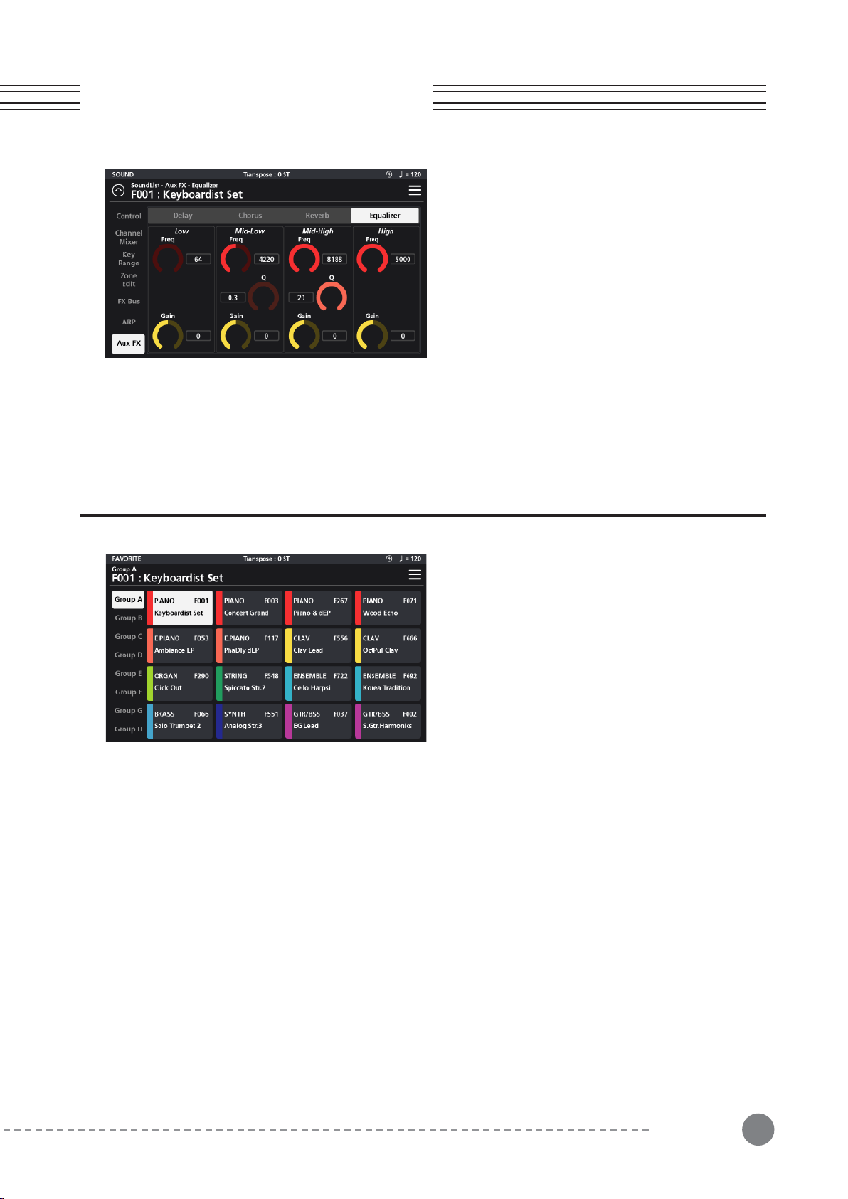
45
Chapter 6
Chapter 6. Favorite Mode
5-2-4 Equalizer
The Equalizer is a 4-band design consisting of Low
(shelving), Mid-Low, Mid-High, and High (shelving)
bands.
Low (Shelf) - A low shelving filter that cuts or boosts
(Gain) frequencies below the set frequency (Freq).
Mid-Low / Mid-High (Peak/Notch) - Fully parametric
bands with controls for specifying the center frequency
(Freq), width of the frequency band around the center frequency (Q) and amount of boost/cut (Gain) for the
specified area.
High (Shelf) - A high shelving filter that cuts or boosts (Gain +/-12dB) frequencies above the set frequency
(Freq).
Chapter 6. Favorite Mode
Press the front panel FAVORITE mode button (above
Sound) to access Favorite mode. Favorite Mode allows
you to conveniently store and quickly recall up to 128 of
your most used sounds. There are 8 groups of favorites
(A - H) that are selectable down the left hand column.
Each group is comprised of 16 tiles organized in a 4x4
grid. Each tile displays the Sound name, ID number and is
color coded by category making it easy to distinguish
each selection.
6-1 Assigning Favorites
1. Go to Sound Mode. Navigate to and select the sound you want to assign as a favorite.
2. Once the desired sound is selected, press the Favorite Mode button to enter Favorite Mode.
3. Select the desired Group (A-H) from the left hand column.
4. Press and hold the selected sound Favorite tile for 3 seconds to store your selection to that tile location.
5. Repeat for any other Favorites you wish to store.
6-2 Recalling Favorites
1. Press the Favorite Mode button to enter Favorite Mode.
2. As needed, select the desired Group (A-H) from the left hand column.
3. To recall a specific favorite from the current group, either tap the on-screen tile or press the corresponding
front panel Sound Category button. Note the Category buttons light to match the on-screen tile selection.
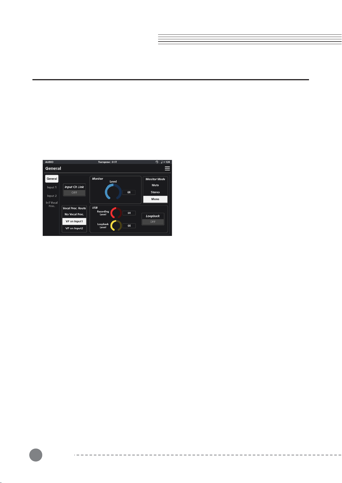
46
Chapter 7. Audio Mode
Chapter 7
Chapter 7. Audio Mode
This chapter provides details on optimal use of the front panel Audio Interface section and rear panel Audio In jacks.
Use the rear panel Audio In jacks to mix external audio sources with the sounds of the SP7 Grand, apply effects to
external audio sources, or route external audio sources to a computer for recording or processing in a DAW. This is
useful for playing along with backing tracks from a portable music player, computer, or other electronic instrument.
Audio mode consists of three menus: General, Input 1, and Input 2.
Adjust all parameter dials by touch, alpha wheel (once selected), Increase+/Decrease- buttons, or tap the value field
to open a numeric keypad for more precise data entry.
7-1 General
The General tab contains settings for Input Ch Link,
Monitor Level, Monitor Mode, Vocal Proc. Route, USB
Recording/Playback Levels and Loopback.
Input Channel Link - This parameter toggles the input
channels’ configuration between dual mono and stereo.
When enabled, this gangs Inputs 1 and 2 together as a
stereo pair. When engaged, input settings are controlled by
the Input 1 page settings and Input 2 settings are inactive.
Monitor Level - This dial adjusts the volume of the
signal entering the back panel Audio In jacks.
Monitor Mode - This switch controls the monitoring configuration of the signal entering the back panel Audio In jacks.
Setting choices include: Mute, Stereo, and Mono.
Vocal Proc. Route - The Vocal Processing can only be used on one input at a time. The Vocal Proc Route switch
determines which input has vocal processing applied to it. You can select: No Vocal Proc., VP on Input 1, or VP on
Input 2.
No Vocal Proc.- Disables all vocal processing.
VP on Input 1 / VP on Input 2 - Select either Input 1 or 2 to have the vocal processing applied to it. Note: when
selecting either input, a new tab menu appears in the left-hand column (“In1 Vocal Proc.” or “In2 Vocal Proc.”)
corresponding to your selection.
USB Recording Level - This dial controls the audio level being sent over USB from the the SP7 Grand to your
computer.
USB Playback Level -This dial controls the audio level being returned over USB from your computer to the SP7
Grand.
Loopback - When enabled, USB audio arriving at the SP7 input is fed back to the USB audio output. This can be
useful for combining backing tracks from your computer/DAW with the output from the SP7 Grand and sending back
to your computer for live recording/streaming. Caution: be sure to disable any input monitoring in your computer
DAW/software to avoid feedback.
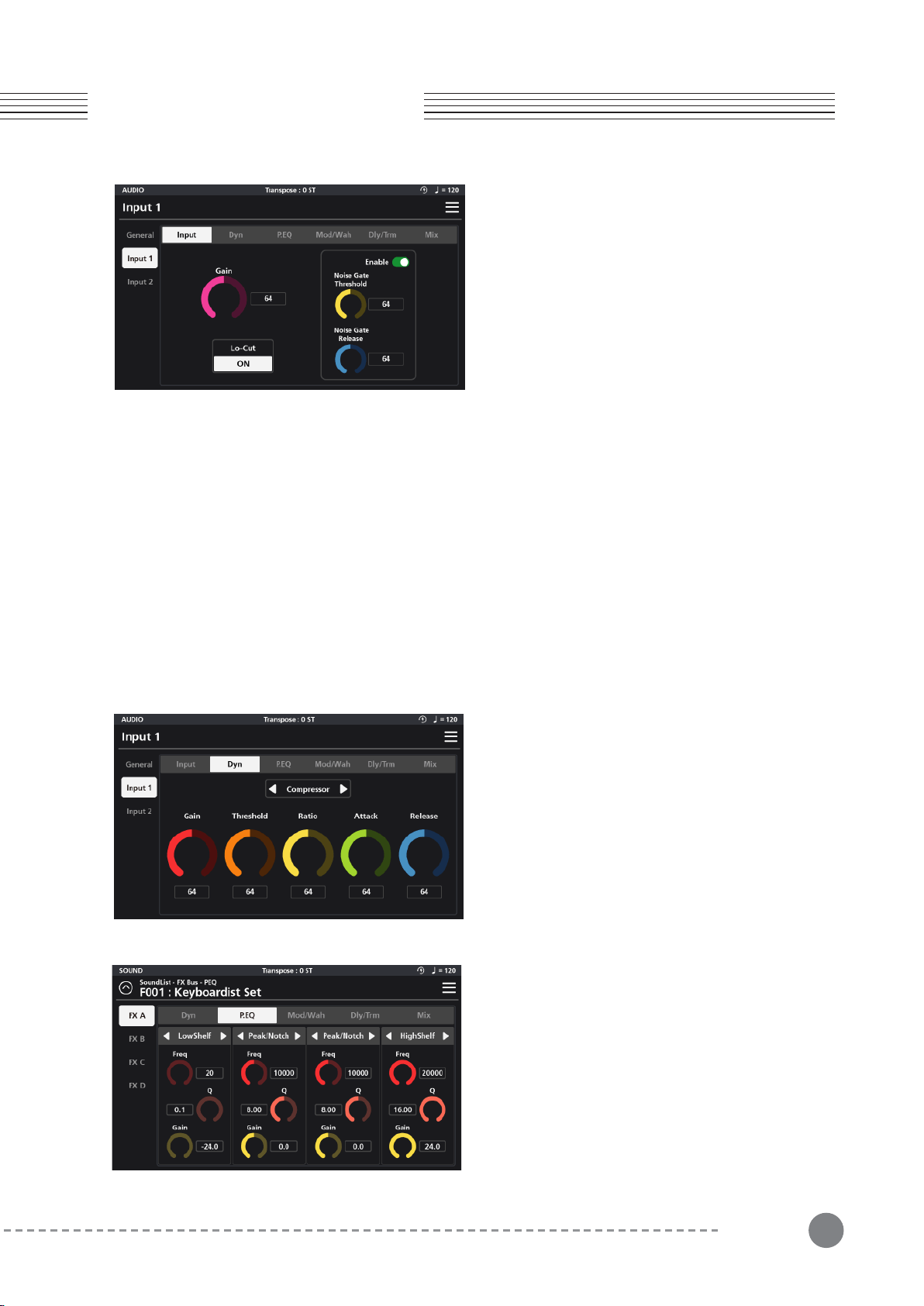
47
7-2 Input 1, 2
Chapter 7
Chapter 7. Audio Mode
Each Input page features the same set of tabs govern-
ing each channel’s operation: Input, Dynamics (Dyn),
Parametric EQ (P.EQ), Simulation/Wah (Mod/Wah),
Delay/Tremolo (Dly/Trm), and Mix.
7-2-1 Input
The Input tab consists of controls for Gain, Lo-Cut filter and a Noise Gate.
Gain - Sets the amount of post input gain feeding into the input processing chain.
Lo-Cut - When enabled, this engages a gentle high-pass filter that reduces unwanted low frequencies.
Noise Gate Enable - This turns the noise gate on (green) and off (red).
Noise Gate Threshold - Sounds below the Threshold value are completely suppressed. Signals louder than the
Threshold, open the gate and are audible.
Noise Gate Release - This sets the time it takes for the gate to close once sound levels drop below the threshold.
Higher values allow for a slower/smoother action while lower values cause the gate to close more quickly.
For details on the following effects tabs and their parameters, please refer back to the earlier noted sections:
7-2-2 Dyn (Dynamic)
see pg 38 (section 5-1-1)
7-2-3 P.EQ (Parametric Equalizer)
The EQ section is a 4-band parametric. With each band,
you can choose from 7 EQ types using the selector tab
at the top of each band: LPF 6dB, LPF 12dB, LowShelf,
Peak/Notch, HighShelf, HPF 6dB and HPF12dB.
For each EQ type (excluding the LPF/HPF) you can set
the frequency (Freq), quality factor (Q), and gain (Gain).
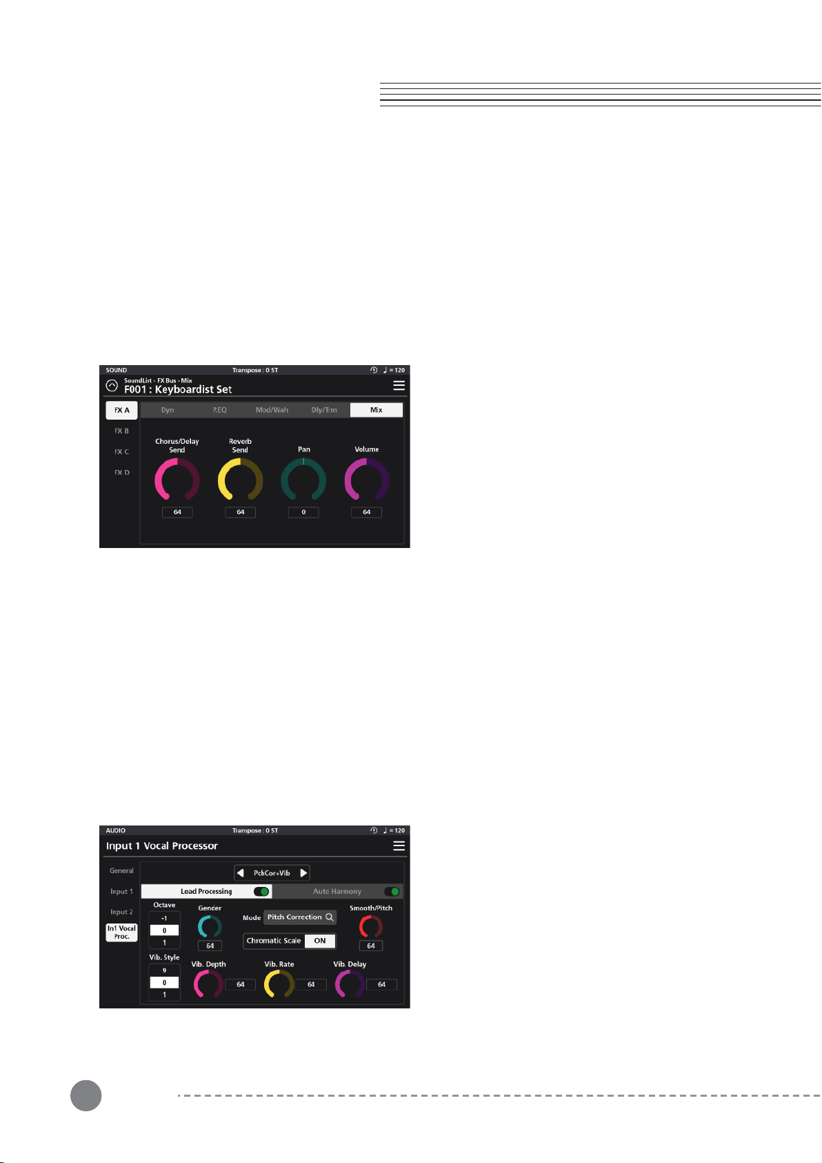
48
Chapter 7. Audio Mode
Chapter 7
LPF 6dB and LPF 12dB - Low pass filters that reduce high frequencies above the set frequency. 6dB and 12dB
slopes are available. The higher the slope, the steeper the cut off.
LowShelf - A low shelving filter that cuts or boosts frequencies below the set frequency.
Peak/Notch - A fully parametric filter with controls for specifying the center frequency (Freq), width of the
frequency band around the center frequency (Q) and amount of boost/cut (gain) for the specified area.
HighShelf - A high shelving filter that cuts or boosts frequencies above the set frequency.
HPF 6dB, HPF 12dB - High pass filters that reduce low frequencies below the set frequency. 6dB and 12dB
slopes are available. The higher the slope, the steeper the cut off.
7-2-4 Mod/Wah (Modulation, Wah)
see pg 39 (section 5-1-3)
7-2-5 Mix
see pg 43 (section 5-1-5)
7-3 In 1, 2 Vocal Proc
The SP7 Grand's Input 1 and 2 Vocal Processors (In 1, 2 Vocal Proc.) provide vocal-specific tools: pitch correction
and auto-harmony generation.
Reminder: the Vocal Processor menu item only appears (in the left column) when you select one of the inputs for
the “Vocal Proc. Route” parameter (Audio / General menu).
The Vocal Processor page is divided into two separate tabs: Lead Processing and Auto Harmony. At the top center
of the page is a preset selector switch which offers the following factory presets with preconfigured pitch correc-
tion and auto-harmony treatments dialed in for you to get you started: Pitch Correction (PchCor), Pitch Correction
+ Vibration (PchCor + Vib), Pitch Correction + Harmony (PchCor + Har), Tight Pitch, Digi Vocal (Digi Vox), Shaky
Vibrato, Fixed Pitch, Robot Vox, Robot Vox2, Octave Up, Flea, Select Harm.
Each process can be manually edited.
7-3-1 Lead Processing
The Lead Processing section consists of the following
parameters: Octave, Gender, Mode, Chromatic Scale
On/Off, Smooth/Pitch, Vibrato Style, Vibrato Rate
(Vib.Rate), Vibrato Depth (Vib.Depth), and Vibrato Delay
(Vib.Delay).

49
Chapter 7
Chapter 7. Audio Mode
7-3-1-1 Octave
Change the octave of the input signal +/- 3 octaves.
7-3-1-2 Gender
Gender alters the input signal to emphasize more male (lower values) or female (higher values) sounding
formants. The default level is 64.
7-3-1-3 Mode
The Mode switch enables/disables the pitch correcting functions and can be set to Constant Pitch, Pitch Correc-
tion or Off.
Set to “Off”, no pitch correction is applied.
Set to “Constant Pitch”, the input signal is forced to play a single fixed pitch as designated by the Smooth/Pitch
dial. Note, when engaged, the Octave setting is inactive.
Set to “Pitch Correction”, the input signal’s pitch is auto-corrected to try and match the absolute pitch.
7-3-1-4 Chromatic Scale
When the Mode is set to Pitch Correction, setting Chromatic Scale “On” attempts to quantize all pitches to the
chromatic scale.
7-3-1-5 Smooth/Pitch
The Smooth/Pitch dial serves a dual purpose.
When the Mode is set to Pitch Correction, the dial acts to smooth the transition between the source and corrected
pitches. Higher values create slower/smoother transitions compared to lower values which are faster/tighter.
When the Mode is set to Constant Pitch, the dial designates the fixed pitch that will be output regardless of the
tuning of the input signal. The parameter value equates to the MIDI note # (Ex 60=C4 (middle C).
7-3-1-6 Vib.Style
The Vibrato Style parameter allows you to select from 10 different shapes of vibrato (0-9).
7-3-1-7 Vib. Rate
Vibrato Rate sets the speed (rate) of vibrato. Higher values generate a faster vibrato. A value of zero (0) effectively
disables the vibrato effect altogether.
7-3-1-8 Vib. Depth
Vibrato Depth sets the range of pitch change. Higher values generate a deeper vibrato. A value of zero (0) effec-
tively disables the vibrato effect altogether.
7-3-1-9 Vib. Delay
Vibrato Delay determines how long after a note begins that the vibrato effect will engage. By delaying the onset of
the effect you can create more natural sounding vibratos. Higher values generate longer delay times.
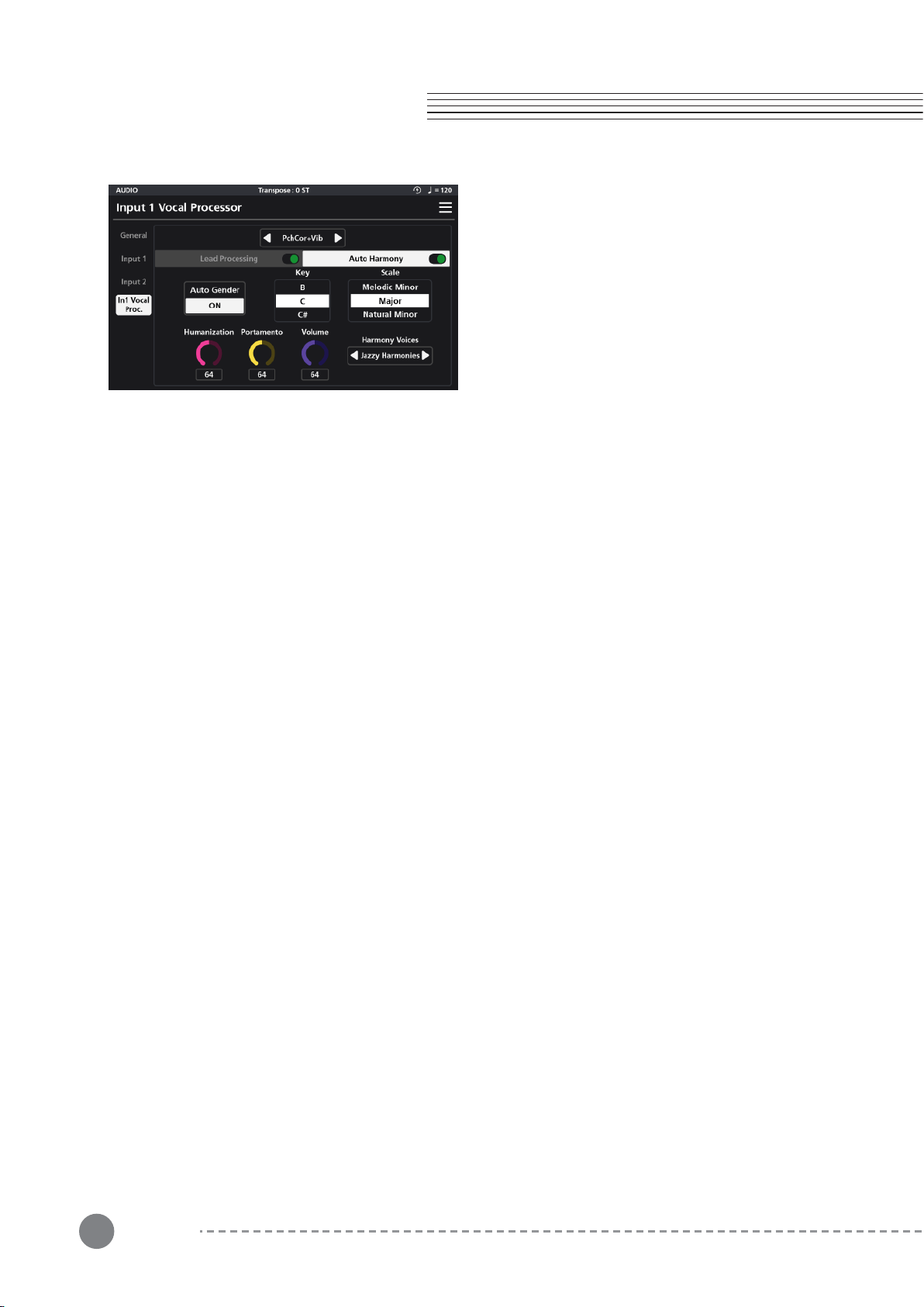
50
Chapter 7. Audio Mode
Chapter 7
7-3-2 Auto Harmony
Auto Harmony is a function that automatically creates
harmonies based off the pitch of the input signal.
Parameter settings include: Auto Gender, Key, Scale,
Humanization, Portamento, Volume, and Harmony
voices.
7-3-2-1 Auto Gender
When enabled, Auto Gender automatically recognizes the gender of the input voice and adjusts the formants of
the generated harmonies to match.
7-3-2-2 Key
Key is used to specify the musical key center that the auto-harmonies will be built around.
7-3-2-3 Scale
Scale defines the musical mode that the harmonies will be generated in.
Choose from: Major, Natural Minor, Harmonic Minor and Melodic Minor.
7-3-2-4 Humanization
Humanization intentionally creates random inaccuracies in the timing and pitch of the generated harmonies,
lending to a more human-like performance. Higher values create a more intense effect. A value of zero (0)
effectively disables the effect altogether.
7-3-2-5 Portamento
Portamento creates a smooth pitch transition between generated harmony notes. Higher values create a slower,
more intense effect. A value of zero (0) effectively disables the effect altogether.
7-3-2-6 Volume
Volume sets the level of the auto-generated harmony parts.
7-3-2-7 Harmony Voices
Harmony Voices determines the structure of the generated harmonies. Selections include: Doubling, Big Unison,
Harmonics 1, Harmonics 2, Jazz Harmonies, Pure Harmonies, Deep Harmonies, Funny Choir, Scary Choir, and
Vocoder.
“Off” effectively disables the Auto Harmony processor.
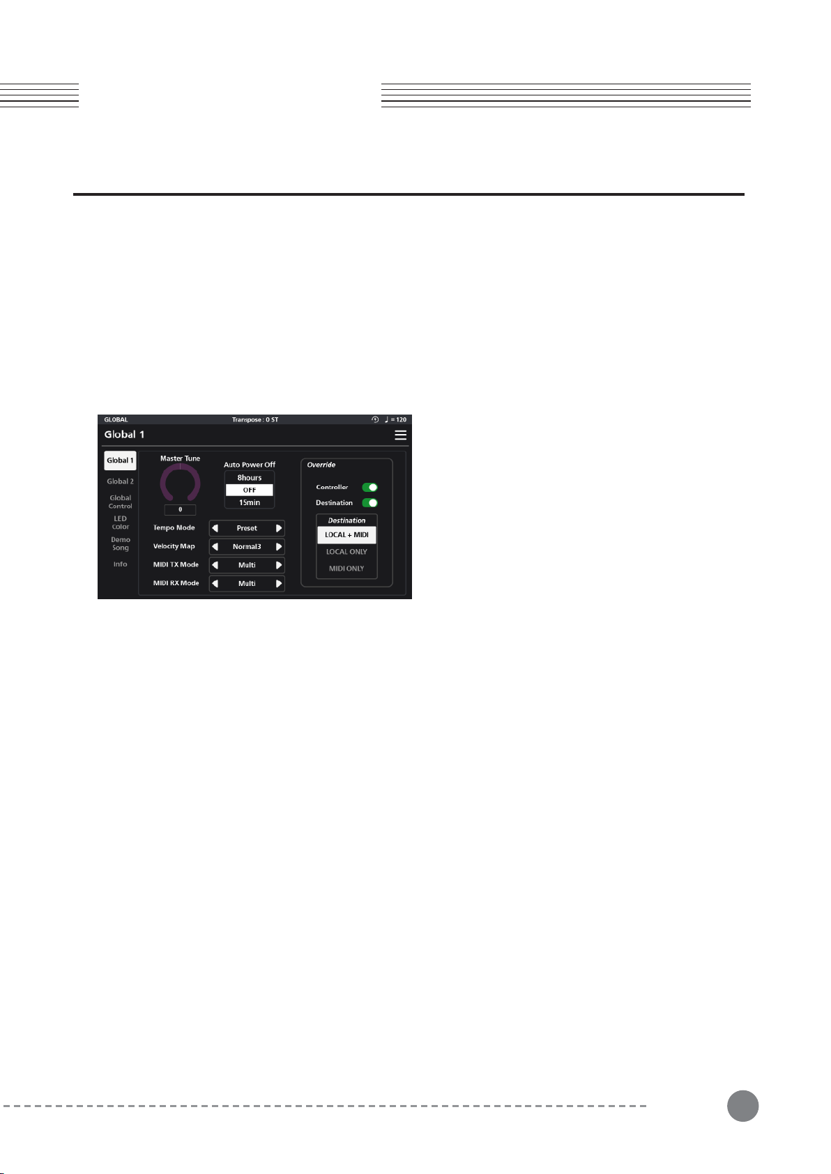
51
Chapter 8
Chapter 8. Audio Mode
Chapter 8. Global Mode
Global Mode allows you to adjust performance settings common to all modes of operation. To enter Global Mode,
press the GLOBAL Mode button.
Global mode contains settings for: tuning, power-saving options, touch screen settings, demo song playback,
accessing the user manuals and for restoring factory settings.
Global mode is divided into 6 pages which are listed down the left side of the screen: Global 1, Global 2, Global
Control, LED Color, Demo Song and Info.
Adjust all parameter dials by touch, alpha wheel (once selected), Increase+/Decrease- buttons, or tap the value field
to open a numeric keypad for more precise data entry.
8-1 Global 1
Global 1 parameters allow you to adjust the Master
Tune, Auto Power Off, Tempo Mode, Velocity Map,
MIDI Transmit Data Mode (MIDI TX Mode), MIDI
Receive Data Mode (MIDI RX Mode) and Override
settings.
8-1-1 Master Tune
Master Tune adjusts the overall pitch of the SP7 Grand (+/- 100 cents).
8-1-2 Auto Power Off
Auto Power Off is a power saving feature. Set the time interval from the last system activity after which the unit
will power itself down (15 min up to 8 hours). The “Off” setting disables the auto power-off feature.
8-1-3 Tempo Mode
Tempo Mode designates whether the current individual Sound or Global Tempo will be the active tempo. When
set to “Preset”, the tempo applied is as specified by the “Preset BPM” tempo parameter for each Sound (Zone
Edit/Common page). When set to “Global” the tempo applied is as specified by the “Tempo” parameter in the
upper right-hand corner drop MENU.
8-1-4 Velocity Map (refer to Appendix 2)
The Velocity Map parameter determines the way the SP7 Grand generates MIDI velocity information. Different
maps generate different MIDI velocity value curves for the same physical key strike. Choose the setting which
best suits your playing style. Choose from Light 1/2/3, Normal 1/2,/3, Hard 1/2/3 and Fixed. Normal 3 is the
default.
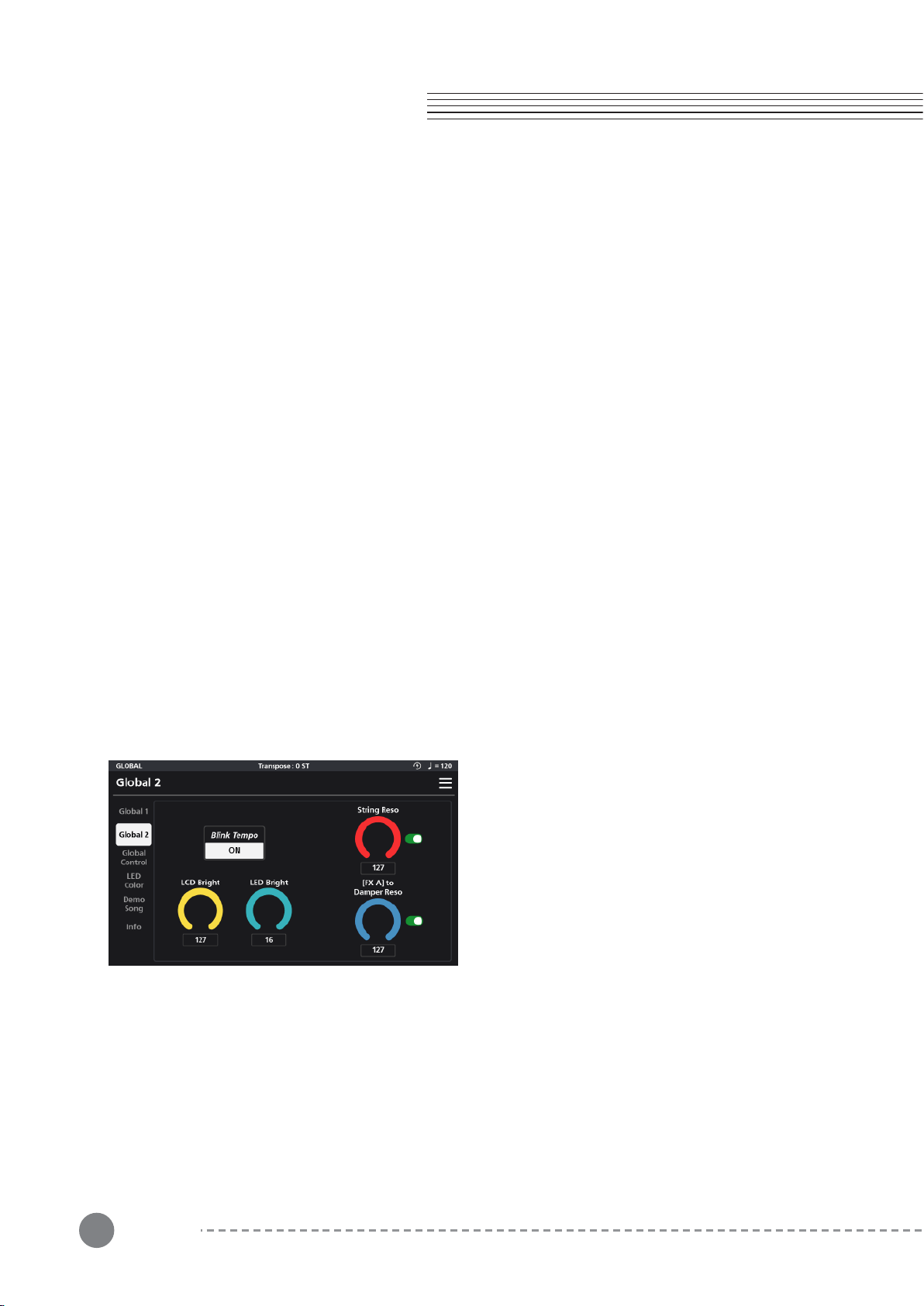
52
Chapter 8. Audio Mode
Chapter 8
8-1-5 MIDI TX Mode
The MIDI Transmit Mode parameter designates whether the SP7 Grand will transmit on multiple MIDI channels or
just channel 1.
When set to “Multi” each zone of the current multi sound will transmit on the MIDI channel which corresponds to
its zone number (Zone 1 receives on channel 1, Zone 2 receives on channel 2, and so on).
When set to “Single” only zone 1/channel 1 transmits.
8-2-1 Blink Tempo
Blink Tempo is a visual aid. When enabled, the large LED ring surrounding the alpha wheel flashes along with the
current system tempo.
8-1-6 MIDI RX Mode
The MIDI Receive Mode parameter designates whether the SP7 Grand will receive on multiple MIDI channels or
just channel 1.
When set to “Multi”, each zone of the current multi sound will receive on the MIDI channel which corresponds to
its zone number (Zone 1 receives on channel 1, Zone 2 receives on channel 2, and so on).
When set to “Single”, only zone 1/channel 1 receives and further, that data is re-channelized to trigger all active
zones as if being played locally on the SP7 Grand keyboard itself.
8-1-7 Override
Each Sound in the SP7 Grand can have its own unique MIDI Controller assignments and Destination routings. The
Override feature allows you to suspend those assignments in lieu of using the settings
found in the Global mode.
When the Controller override switch is on (green), the Controller assignments (as defined under the Global Control
menu) will take precedence over the settings within each Sound.
When the Destination override switch is on (green), a routing selector tab appears allowing you to select the MIDI
routing. It takes precedence over the settings within each Sound. Three configurations are available:
ㆍLOCAL+MIDI (MIDI data is sent internally to the SP7 Grand and external devices)
ㆍLOCAL ONLY (MIDI data is only sent internally to the SP7 Grand)
ㆍMIDI ONLY (MIDI data is only sent to external devices).
8-2 Global 2
Global 2 parameters allow you to adjust the Blink
Tempo, LCD Bright, LED Bright, String Resonance, and
[FX A] to Damper Resonance.
8-2-2 LCD Bright
LCD Brightness adjusts the brightness of the touch screen.
8-2-3 LED Bright
LED Brightness adjusts the brightness of the front panel knobs and buttons.
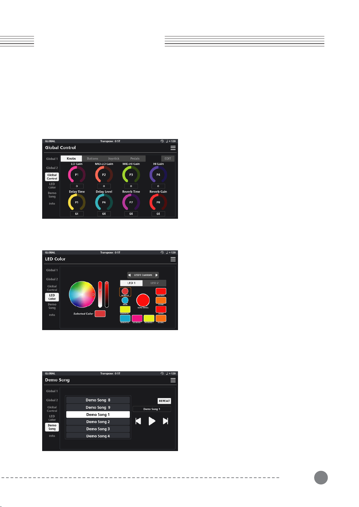
53
Chapter 8
Chapter 8. Audio Mode
8-2-4 String Resonance
When enabled (switch is green) the String Resonance (String Reso.) dial controls the amount of sympathetic
string resonance generated with the acoustic pianos.
8-2-5 [FXA] to Damper Resonance
When enabled (switch is green) the [FX A] to Damper Resonance dial controls the amount of post FX A signal that
gets fed through the damper resonant effect.
8-3 Global Control
8-4 LED Color
8-5 Demo Song
In Global Control, you can view and edit the global
assignments of the Knobs, Buttons, Joysticks and
Pedals.
Note: once edited, the Controller Override parameter
(Global 1 page) gets auto-enabled and the Global
Control override the individual Sound settings.
The LED Color menu allows you to customize the colors
of all of the non-programmable knobs/buttons on the
front panel: Monitor, Main, Transpose, Alpha Wheel,
Increase/Decrease, Mode and Category buttons.
The front panel controls are divided on screen into two
editing groups, LED 1 and LED 2. LED 1 contains all the
dials and buttons minus the Category buttons and LED
2 contains the grid of 16 Category buttons.
A Default/Custom switch above these two groups
allows you to toggle between the system default color
In the Demo Song menu you can listen to the SP7
Grand’s 9 built-in song demos. Select from the list of
songs and use the transport buttons on the right to
control playback. Enable “Repeat” to play all of the
songs in a continuous loop.
*For detailed settings and contents of Global Control Editing,
refer to the Controller Editing section of Chapter 3 Sound
Editing.
assignments and custom settings.To customize the color for any given control, select “Custom” from the
Default/Custom switch, tap the intended on-screen control, then adjust the color palette wheel, brightness, and
contrast control bars to taste.
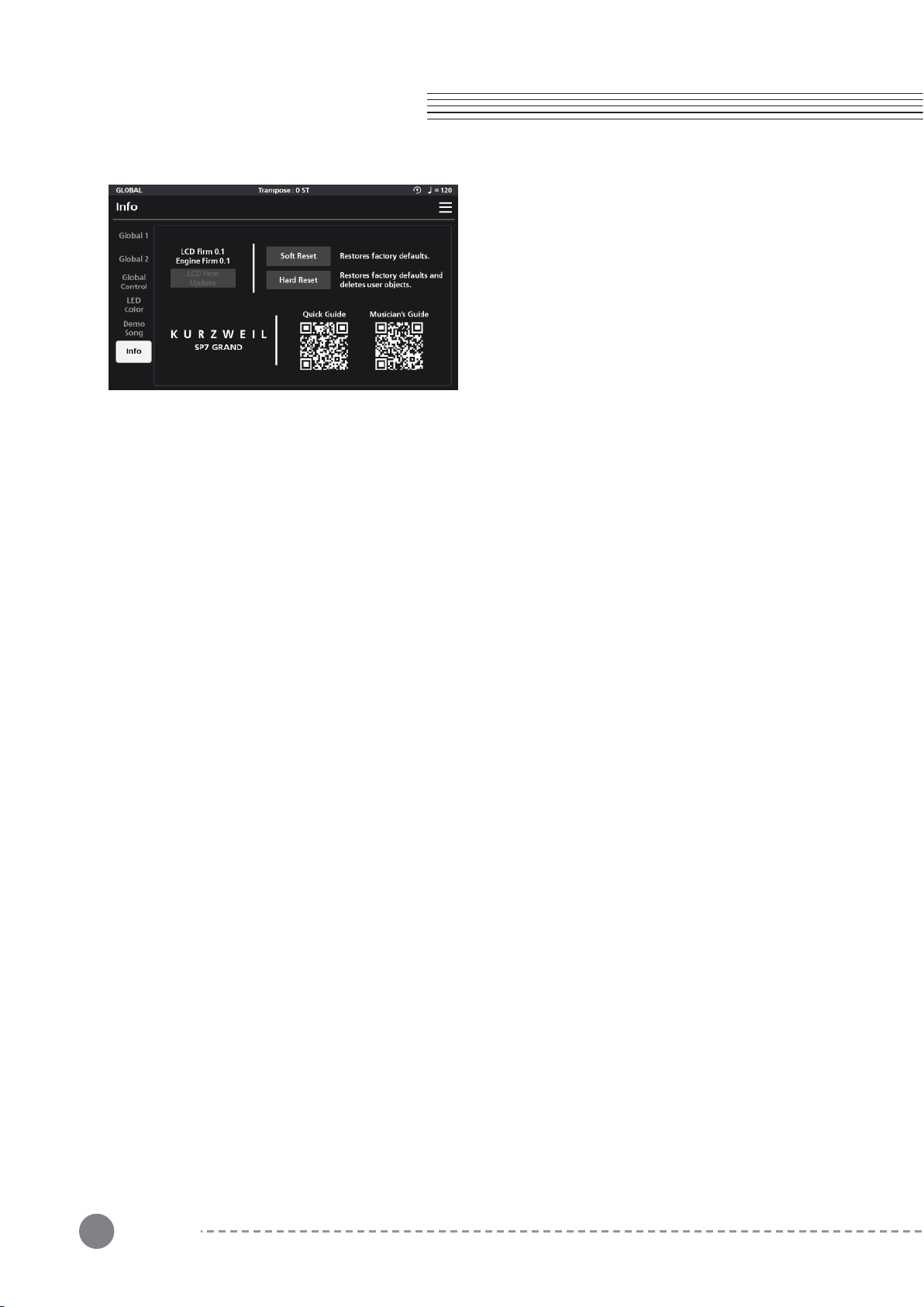
54
Chapter 8
Chapter 8. Global Mode
8-6 Info
8-7 Menu
In the Info menu, you can check the currently installed
LCD and Engine Firmware versions as well as reset the
system and gain access to the user manuals via QR
code.
Soft Reset and Hard Reset initialization settings.
“Soft Reset” restores the factory default system settings while maintaining user presets.
“Hard Reset” erases all information including user presets and completely resets the SP7 Grand to its factory
default settings.
Selecting either reset option will display a pop-up screen asking you to confirm the operation (Reset) or to Cancel
it. Selecting Reset will clear the designated settings and the unit will power itself off. Power back on to return to
normal operation.
Manuals and Updates
Easily access the SP7 Grand Quick Guide and User Manual by scanning the on-screen QR codes.
Be sure to periodically check www.kurzweil.com for the latest system updates.
In all modes, there is a 3 horizontal icon in the upper right hand corner of the display screen. This is the MENUE
icon, providing quick access to the Save, Arpeggiator on/off switch, system tap Tempo, MIDI Panic, and Screen
Lock functions.
Save - When in Sound Edit mode, a Save option appears in the Menu offering a shortcut to the Save dialog.
ARP (Arpeggiator On/Off) - This is a master on/off switch for all of the arpeggiators in the SP7 Grand.
This provides a fast way to temporarily disable the arp engines. Tap to toggle between active and inactive.
Tempo - This menu opens a tap tempo screen allowing you to set the current tempo in increments or by tapping.
Panic - Pressing panic resets all MIDI messages and is a handy tool when stuck notes and/or other MIDI gremlins
appear.
Lock - Pressing the lock icon temporarily suspends all screen and front panel input. This is a valuable feature
preventing unwanted adjustments to ones settings when the keyboard is left unattended. A lock symbol will
appear in the top beam of the screen when active. Simply press the lock symbol to unlock.
55
Supplementary
Provisions (1)
Supplementary
Provisions (1)
MIDI CC Note MIDI CC Note MIDI CC Note
0 Bank Select 43 CC 43 86 CC 86
1 Mod Wheel 44 CC 44 87 CC 87
2 CC 2 45 CC 45 88 CC 88
3 CC 3 46 CC 46 89 CC 89
4 CC 4 47 CC 47 90 CC 90
5 Porta.Time 48 CC 48 91 CC 91
6 Data Entry 49 CC 49 92 CC 92
7 Zone Volume 50 CC 50 93 CC 93
8 CC 8 51 CC 51 94 CC 94
9 CC 9 52 CC 52 95 CC 95
10 Pan 53 CC 53 96 CC 96
11 Expression 54 CC 54 97 CC 97
12 CC 12 55 CC 55 98 CC 98
13 CC 13 56 CC 56 99 CC 99
14 CC 14 57 CC 57 100 CC 100
15 CC 15 58 CC 58 101 CC 101
16 CC 16 59 CC 59 102 CC 102
17 CC 17 60 CC 60 103 CC 103
18 CC 18 61 CC 61 104 CC 104
19 CC 19 62 CC 62 105 CC 105
20 CC 20 63 CC 63 106 CC 106
21 CC 21 64 Sustain 107 CC 107
22 CC 22 65 Porta.On/Off 108 CC 108
23 CC 23 66 Sostenuto 109 CC 109
24 CC 24 67 Soft Pedal 110 CC 110
25 CC 25 68 CC 68 111 CC 111
26 CC 26 69 CC 69 112 CC 112
27 CC 27 70 CC 70 113 CC 113
28 CC 28 71 Resonance 114 CC 114
29 CC 29 72 Env release 115 CC 115
30 CC 30 73 Env attack 116 CC 116
31 CC 31 74 Cutoff 117 CC 117
32 CC 32 75 Env decay 118 CC 118
33 CC 33 76 Vib rate 119 CC 119
34 CC 34 77 Vib depth 120 CC 120
35 CC 35 78 Vib delay 121 CC 121
36 CC 36 79 CC 79 122 CC 122
37 CC 37 80 CC 80 123 CC 123
38 CC 38 81 CC 81 124 CC 124
39 CC 39 82 CC 82 125 CC 125
40 CC 40 83 CC 83 126 CC 126
41 CC 41 84 CC 84 127 CC 127
42 CC 42 85 CC 85
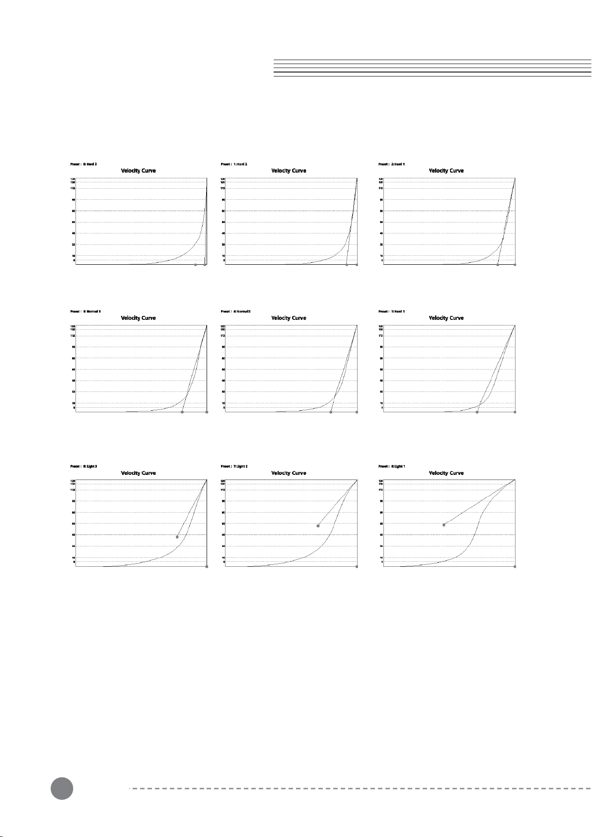
56
Supplementary
Provisions (2)
Supplementary
Provisions (2)
MIDI CC
57
Chapter 8
Product
Specification
Keyboard Italian 88-note, fully-weighted hammer-action keyboard (Fatar TP/110).
Display 1024 x 600 pixel, high resolution 7″ color LCD touch screen
Polyphony 256
Programs 512 factory multis.
USB MIDI & Audio Interface
Line I/O 2 XLR combo inputs
Product size 1320mm X 377mm X 120mm
Weight 16.6Kg
Power DC Power adapter : 15V , 2.5A
Pedal Input
2 Switch pedal inputs; supports a single half-damper pedal (1 switch/sustain
pedal is included; half-damper pedals sold separately)
1 Continuous Control Pedal Input (pedal sold separately)
Headphone
output
1/4" stereo headphone output.
Additional
accessories
Acrylic music board (sold separately)

58
Memo
memo

59memo

Head office : 196, Bongsu-daero, Seo-gu, Incheon
A/S Tel : +08-32-570-1550 ~ 3