
525RX Mark II, 525RXT Mark II
EN Operator's manual 2-26
Contents
Introduction..................................................................... 2
Safety..............................................................................4
Assembly........................................................................ 9
Operation...................................................................... 12
Maintenance................................................................. 18
Troubleshooting............................................................ 21
Transportation and storage...........................................22
Technical data.............................................................. 23
Accessories.................................................................. 24
Declaration of Conformity............................................. 25
Introduction
Product description
This product is a brushcutter with a combustion engine.
Work is constantly in progress to increase your safety
and efficiency during operation. Speak to your servicing
dealer for more information.
Intended use
Use the product with a saw blade, a grass blade or a
trimmer head to cut different types of vegetation. Do
not use the product for other tasks than grass trimming,
grass clearing and forestry clearing. Use a saw blade to
cut fibrous types of wood. Use a grass blade or trimmer
head to cut grass.
Note: National or local regulations can regulate the
use. Comply to given regulations.
Only use the product with accessories that are approved
by the manufacturer. Refer to
Accessories on page 24
.
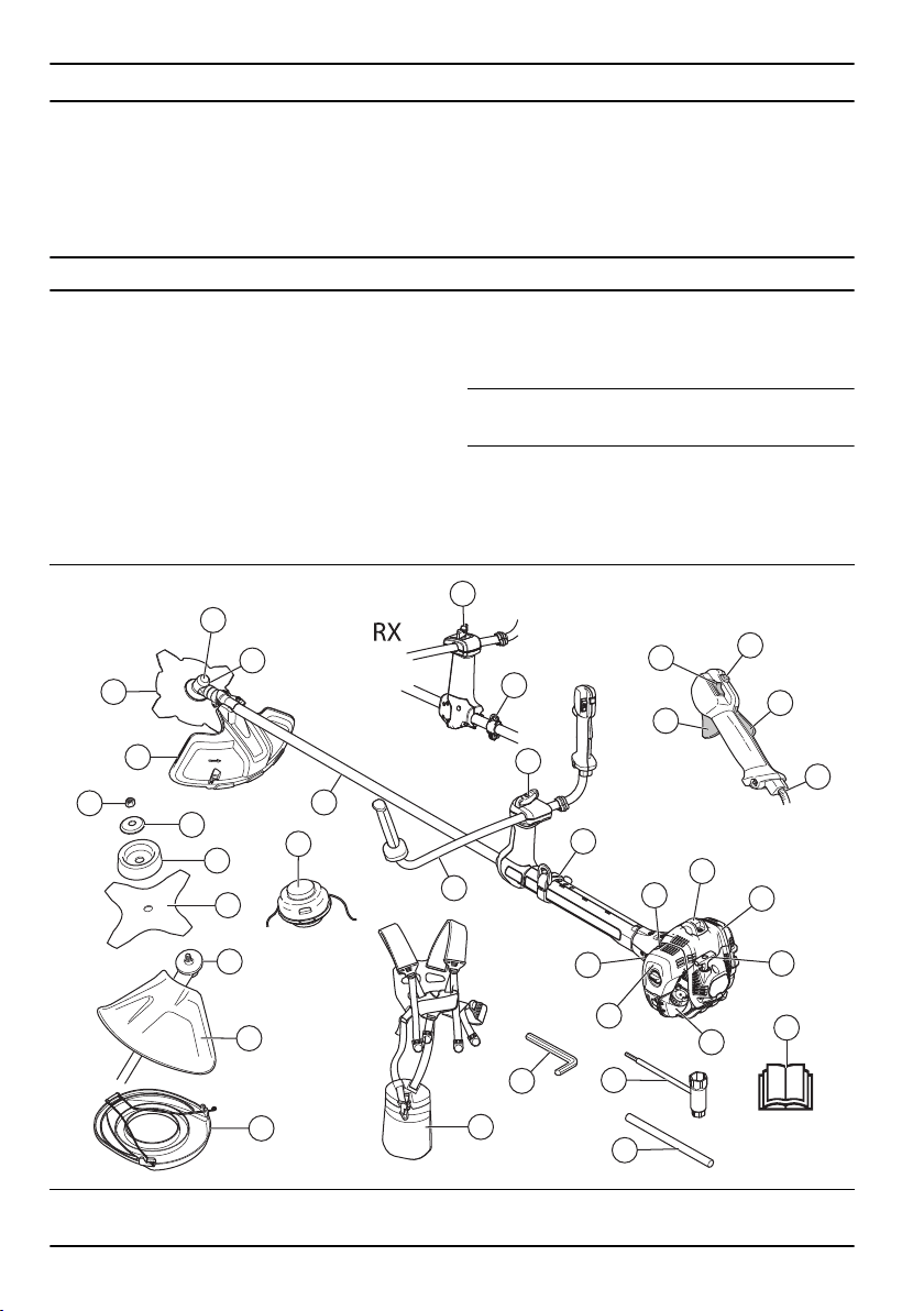
Product overview
7
8
9
21
4
10
17
18
19
20
1
22
25
23
24
26
27
28
29
31
1
2
3
4
5
6
10
11
12
13
14
15
16
30
17
1. Blade 2. Grease filler cap, bevel gear
2 1818 - 006 - 20.12.2022
3. Bevel gear
4. Cutting attachment guard
5. Shaft
6. Handlebar
7. Throttle control
8. Stop switch
9. Throttle lockout
10. Suspension ring
11. Cylinder cover
12. Starter rope handle
13. Fuel tank
14. Choke control
15. Air purge bulb
16. Air filter cover
17. Handle adjustment
18. Locknut
19. Support flange
20. Support cup
21. Drive disc
22. Trimmer head
23. Socket wrench
24. Operator's manual
25. Transport guard
26. Locking pin
27. Harness
28. Start throttle button
29. Throttle cable adjuster
30. Spark plug cap and spark plug
31. Hex key
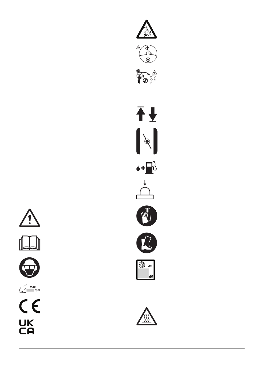
Symbols on the product
WARNING! Be careful and use the
product correctly. This product can cause
serious injury or death to the operator or
others.
Read the operator's manual carefully
and make sure that you understand the
instructions before you use this product.
Use a protective helmet in locations where
objects can fall on you. Use approved
hearing protection and approved eye
protection.
Maximum speed of the output shaft.
The product agrees with the applicable
EC directives.
This product conforms to applicable UK
regulations.
The product can cause objects to eject,
which can cause injury.
5
0
FT
1
5
m
50F
T
15 m
Keep a minimum distance of 15 m/50 ft. to
persons and animals during operation of
the product.
Risk of blade thrust if the cutting
equipment touches an object that it does
not immediately cut. The product can cut
off body parts. Keep a minimum of 15 /50
ft. distance to persons and animals during
operation of the product.
The arrows shows the limit for the handle
position.
Choke.
Fuel.
Air purge bulb.
Use approved protective gloves.
Use heavy-duty slip-resistant boots.
Noise emission to the environment
label as per EU and UK directives
and regulations, and New South Wales
legislation "Protection of the Environment
Operations (Noise Control) Regulation
2017". The guaranteed sound power level
of the product is specified in
Technical
data on page 23
and on the label.
Keep all parts of your body away from hot
surfaces.
1818 - 006 - 20.12.2022 3
yyyywwxxxx The rating plate shows the
serial number. yyyy is the
production year and ww is
the production week.
Note: Other symbols/decals on the product refer to
certification requirements for other commercial areas.
Euro V Emissions
WARNING: Tampering with the engine
voids the EU type-approval of this product.
Safety
Safety definitions
The definitions below give the level of severity for each
signal word.
WARNING: Injury to persons.
CAUTION: Damage to the product.
Note: This information makes the product easier to
use.
General safety instructions
WARNING: Read the warning
instructions that follow before you use the
product.
• Use the product correctly. Injury or death is a
possible result of incorrect use. Only use the product
for the tasks found in this manual. Do not use the
product for other tasks.
• Obey the instructions in this manual. Obey the safety
symbols and the safety instructions. If the operator
does not obey the instructions and the symbols,
injury, damage or death is a possible result.
• Do not discard this manual. Use the instructions
to assemble, to operate and to keep your product
in good condition. Use the instructions for correct
installation of attachments and accessories. Only
use approved attachments and accessories.
• Do not use a damaged product. Obey the
maintenance schedule. Only do the maintenance
work that you find an instruction about in this
manual. An approved service center must do all
other maintenance work.
• This manual cannot include all situations that can
occur when you use the product. Be careful and use
your common sense. Do not operate the product or
do maintenance on the product if you are not sure
about of the situation. Speak to a product expert,
your dealer, service agent or approved service
center for information.
• Disconnect the spark plug cable before you
assemble the product, put the product into storage
or do maintenance.
• Do not use the product if it is changed from its initial
specification. Do not change a part of the product
without approval from the manufacturer. Only use
parts approved by the manufacturer. Injury or death
is a possible result of incorrect maintenance.
• Do not breathe in the fumes from the engine. Long-
term inhalation of the engine's exhaust fumes is a
health risk.
• Do not start the product indoors or near flammable
material. The exhaust fumes are hot and can contain
a spark which can start a fire. Not sufficient airflow
can cause injury or death because of asphyxiation or
carbon monoxide.
• When you use this product the engine makes an
electromagnetic field. The electromagnetic field can
cause damage to medical implants. Speak to your
physician and medical implant manufacturer before
you operate the product.
• Do not let a child operate the product. Do not let a
person without knowledge of the instructions operate
the product.
• Make sure that you always monitor a person, with
decreased physical capacity or mental capacity, that
uses the product. A responsible adult must be there
at all times.
• Lock the product in an area that children and
unapproved persons cannot access.
• The product can eject objects and cause injuries.
Obey the safety instructions to decrease the risk of
injury or death.
• Do not go away from the product when the engine is
on.
• The operator of the product is responsible if an
accident occurs.
• Make sure that parts are not damaged before you
use the product.
• Make sure that you are at minimum 15 m (50 ft)
away from other persons or animals before you use
the product. Make sure that persons in the adjacent
area know that you will use the product.
4
1818 - 006 - 20.12.2022
• Refer to national or local laws. They can prevent
or decrease the operation of the product in some
conditions.
• Do not use the product if you are fatigued or
influenced by alcohol, drugs or medicine. They can
have effects on your vision, alertness, coordination
or judgment.
Safety instructions for assembly
WARNING: Read the warning
instructions that follow before you use the
product.
• Use approved protective gloves when you assemble
the product and cutting attachment.
• Remove the spark plug cap from the spark plug
before you assemble the product.
• Make sure that the correct handlebar and cutting
attachment guard are assembled before you operate
the product.
• A defective or incorrect cutting attachment guard can
cause injury. Do not use a cutting attachment without
an approved cutting attachment guard.
• Attach the clutch cover and shaft correctly before
you start the product.
• The drive disc and support flange must engage
correctly in the center hole of the cutting attachment.
A cutting attachment that is attached incorrectly can
cause injury or death.
• Attach the harness to the product to prevent injury to
the operator or others.
Safety instructions for operation
• Make sure the product is fully assembled before you
use it.
• Before a start, move the product 3 m (10 ft) away
from the position where you filled the fuel tank. Put
the product on a flat surface. Make sure that the
cutting attachment does not touch the ground or
other objects.
• The product can cause objects to eject, which can
cause damage to the eyes. Always use an approved
eye protection when you operate the product.
• Be careful, a child can come near the product
without your knowledge during operation.
• Do not operate the product if there are persons in
the work area. Stop the product if a person goes into
the work area.
• Make sure that you are always in control of the
product.
• Do not use the product if you cannot receive aid if an
accident occurs. Always make sure others know you
will operate the product before you start to operate
the product.
• Do not turn with the product before you make sure
that no persons or animals are in the safety area.
• Remove all unwanted materials from the work area
before you start. If the cutting attachment hits an
object, the object can eject and cause injury or
damage. Unwanted material can wind around the
cutting attachment and cause damage.
• Do not use the product in bad weather (fog, rain,
strong winds, risk of lightning or other weather
conditions). Dangerous conditions (such as slippery
surfaces) can occur because of bad weather.
• Make sure that you can move freely and work in a
stable position.
• Make sure that you cannot fall when you use the
product. Do not tilt when you operate the product.
• Always hold the product with your two hands. Hold
the product on the right side of your body.
• Always use the harness. Make sure that you attach
the harness to the suspension ring.
• Operate the product with the cutting attachment
below your waist.
• If the choke control is in the choke position when the
engine starts, the cutting attachment starts to turn.
• Do not touch the bevel gear after the engine stops.
The bevel gear is hot after the engine stops. Hot
areas can cause injury.
• Stop the engine before you move the product.
• Do not put down the product with the engine on.
• Before you remove the unwanted materials from the
product, stop the engine and wait until the cutting
attachment stops. Let the cutting attachment stop
before you or an aid remove the cut material.
Personal protective equipment
WARNING:
Read the warning
instructions that follow before you use the
product.
• Always use correct personal protective equipment
when you operate the product. The personal
protective equipment does not erase the risk of
injury. The personal protective equipment decreases
the grade of injury if an accident occurs.
• Always use an approved eye protection while you
operate the product.
• Do not operate the product with bare feet or with
open shoes. Always use heavy-duty slip-resistant
boots.
• Use heavy, long pants.
1818 - 006 - 20.12.2022
5
• If it is necessary, use approved protective gloves.
• Use a helmet if it is possible that objects fall on your
head.
• Always use approved ear protection while you
operate the product. Noise for a long period can
cause noise-induced hearing loss.
• Make sure that you have a first aid kit near.
Protective devices on the product
• Make sure that you regularly do the maintenance to
the product.
• The life of the product increases.
• The risk of accidents decreases.
Let an approved dealer or an approved service
center regularly examine the product to do
adjustments or repairs.
• Do not use a product with damaged protective
equipment. If the product is damaged, speak to an
approved service center.
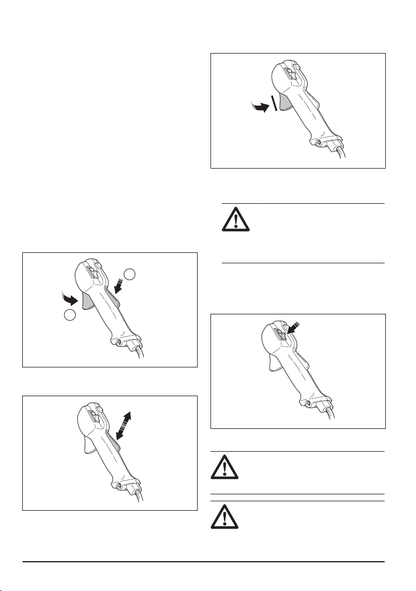
To do a check of the throttle trigger lockout
1. Make sure that the throttle trigger lockout (A) and
throttle trigger (B) move freely and that the return
spring operates correctly.
A
B
2. Push down the throttle trigger lockout and make
sure that it goes back to its initial position when you
release it.
3. Make sure that the throttle trigger is locked at the
idle position when the throttle trigger lockout is
released.
4. Start the product and apply full throttle.
5. Release the throttle trigger and make sure that the
cutting attachment stops and stays stationary.
WARNING: If the cutting
attachment moves when the throttle
trigger is in the idle position, then the
carburetor idle speed must be adjusted.
Refer to
To adjust the idle speed on
page 19
.
To do a check of the stop switch
1. Start the engine.
2. Move the stop switch to the stop position and make
sure that the engine stops.
To do a check of the cutting attachment guard
WARNING:
Do not use a cutting
attachment without an approved and
correctly attached cutting attachment guard.
Refer to,
Accessories on page 24
.
WARNING: Always use the
recommended cutting attachment guard for
the cutting attachment that you use. If an
incorrect or faulty cutting attachment guard
6 1818 - 006 - 20.12.2022
is fitted this can cause serious personal
injury. Refer to,
Technical data on page 23
.
The cutting attachment guard prevents injuries from
objects that eject in the direction of the operator. It
also prevents injuries that occur if you touch the cutting
attachment.
1. Do a visual check for damages, for example cracks.
2. Replace the cutting attachment guard if it is
damaged.
To do a check of the vibration damping system
The vibration damping system decreases vibration in
the handles to a minimum which makes the operation
easier.
1. Stop the engine.
2. Do a visual check for deformation and damage, for
example cracks.
3. Make sure that the elements of the vibration
damping system are attached correctly.
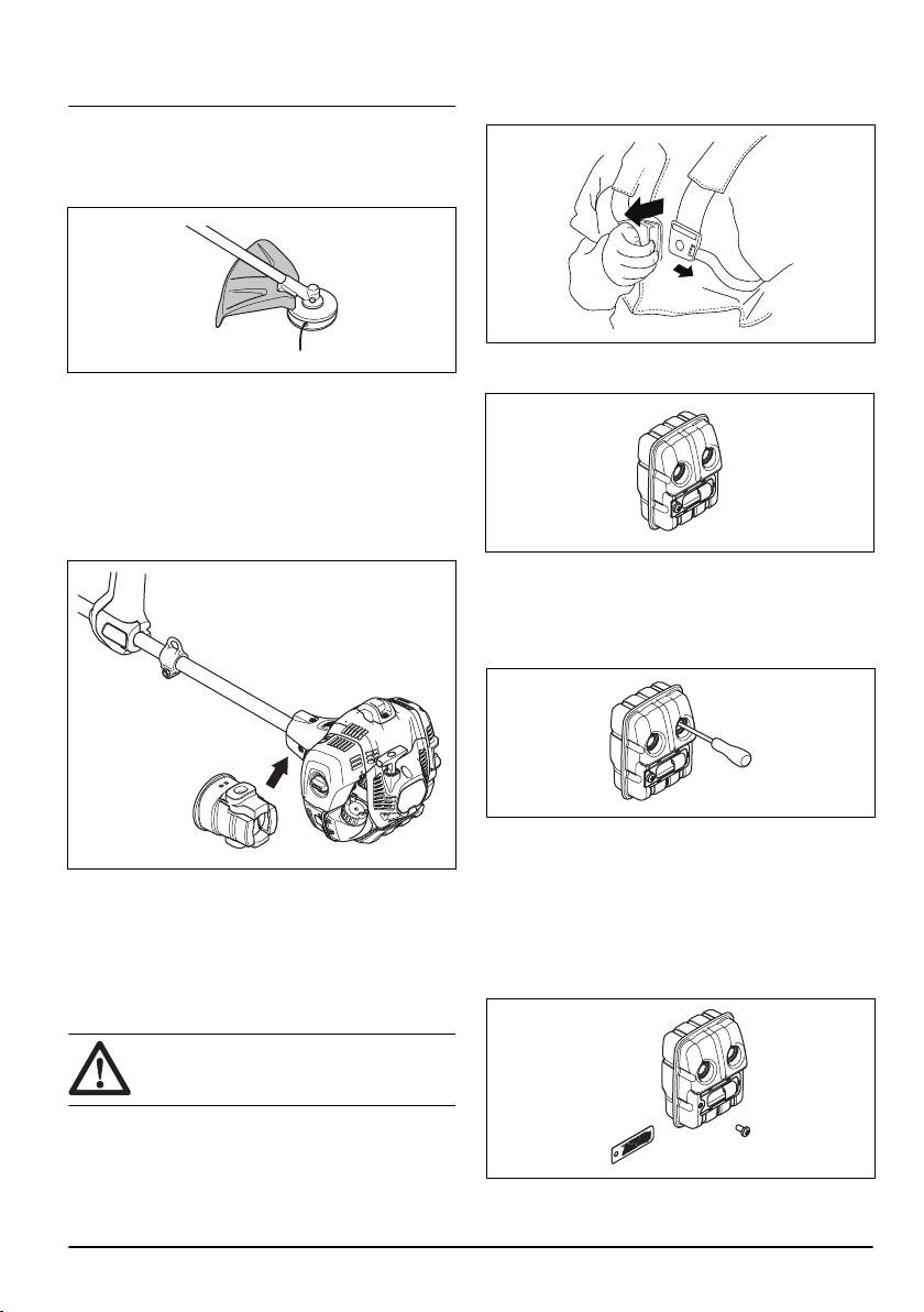
To do a check of the quick-release mechanism
WARNING: Do not use a harness with
a defective quick-release mechanism.
The quick-release mechanism lets the operator remove
the product quickly from the harness if there is an
emergency.
1. Stop the engine.
2. Do a visual check for damage, for example cracks.
3. Release and attach the quick-release mechanism to
make sure that it operates correctly.
To do a check of the muffler
The muffler keeps noise levels to a minimum and sends
exhaust fumes away from the operator.
• Do a visual check for damage and deformation.
• Make sure that the muffler is correctly attached to
the product.
• If the muffler on your product has a spark arrester
screen, do a visual check. Replace the spark
arrester screen if it is damaged.
a) Clean the spark arrester screen if it is blocked. A
blocked spark arrester screen causes the engine
to become too hot which causes damage to the
engine.
b) Make sure that the spark arrestor mesh is
attached correctly.
1818 - 006 - 20.12.2022
7
Cutting equipment
Choose and maintain the cutting equipment to:
• Obtain maximum cutting performance.
• Increase life span of the cutting equipment.
• Follow the checking, maintenance and service
instructions for the muffler.
• Always use the recommended guard for the cutting
equipment. See Technical data.
WARNING: Only use cutting
attachments with the guards we
recommend! See the chapter on Technical
data. Refer to the instructions for the cutting
attachment to check the correct way to load
the trimmer line and the correct trimmer line
diameter.
WARNING: A faulty cutting attachment
may increase the risk of accidents.
WARNING: Always stop the engine
before doing any work on the cutting
attachment. This continues to rotate even
after the throttle has been released. Ensure
that the cutting attachment has stopped
completely and disconnect the spark plug
cap before you start to work on it.
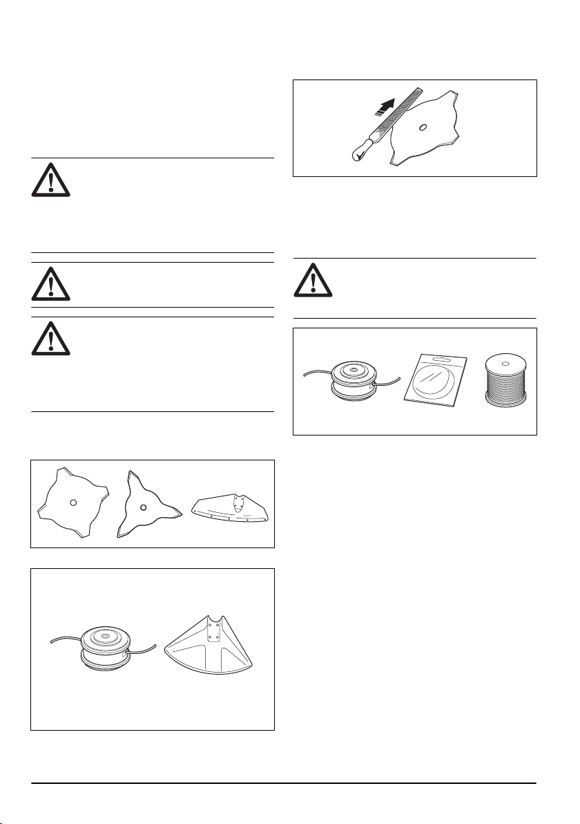
Cutting equipment
• Use the blades and grass knives to cut coarse grass.
• Use the trimmer head to cut grass.
• An incorrectly sharpened or damaged blade
increases the risk of accidents. Keep the teeth of the
blade correctly sharpened. Obey the instructions in
To sharpen grass cutters and grass blades on page
21
and use the recommended file gauge.
• Examine the cutting attachment for damage and
cracks. Replace the damaged cutting attachment.
• Only use cutting attachments with recommended
guards. Refer to
Accessories on page 24
.
Trimmer head
WARNING: Always make sure the
trimmer line is wound tightly and evenly
around the drum to prevent harmful
vibration.
• Only use recommended trimmer heads and trimmer
lines.
• Only use recommended cutting attachments.
• Smaller machines requires small trimmer heads and
vice versa.
• The length of the trimmer line is important. A longer
trimmer line requires greater engine power than a
shorter trimmer line of the same diameter.
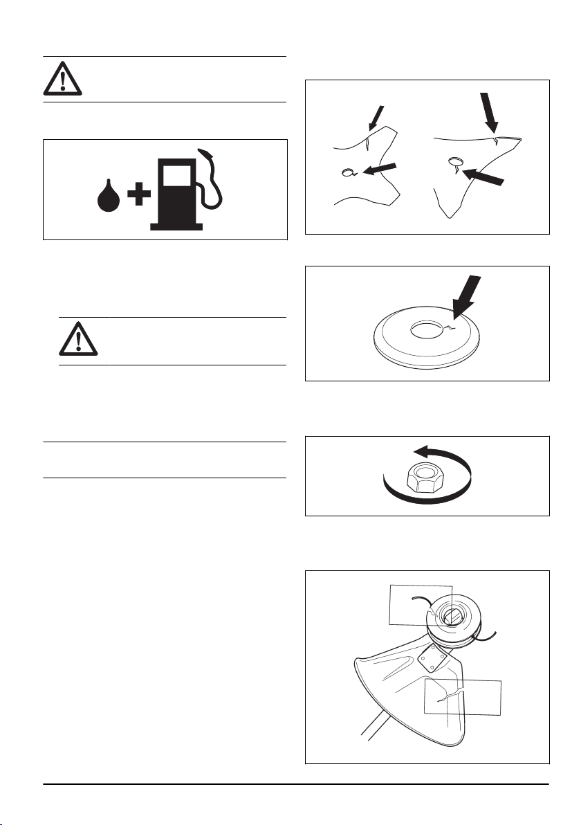
• Make sure that the cutter on the trimmer guard
is intact. This cuts the trimmer line to the correct
length.
• Soak the trimmer line in water for a couple of days
before use to increase the life length.
Grass blades and grass cutters
• Use the product with an approved grass blade. Do
not use a grass blade without proper installation of
all required parts. Make sure that the installation is
done correctly and that the proper parts are used.
Improper installation may cause the blade to fly off
and seriously injure the operator or the bystanders.
• Wear protective gloves when you handle or do
maintenance on the blade.
• Use head protection when you operate a product
with a grass blade.
8
1818 - 006 - 20.12.2022

• Grass blades and grass cutters are used to cut
rough grass.
• A grass blade can cause injury while it continues
to spin after the engine is stopped or the throttle
trigger is released. Make sure that the grass
blade has completely stopped rotating before any
maintenance.
• Stop the engine before you do work on the cutting
attachment. Make sure the cutting attachment fully
stops. Disconnect the lead from the spark plug.
• Only use an approved cutting attachment or a
correctly sharpened blade.
• Keep the teeth of the blade correctly sharpened.
• Do not use a damaged cutting attachment.
• Attach the transport guard to the grass blade when
you transport or store the product.
Blade thrust
• A blade thrust is a sudden movement of the product
to the side, forward or rearward. A blade thrust
occurs when the grass blade hits an object that
cannot be cut. In areas where it is not easy to
see the material being cut the risk of blade thrust
increases.
• When a blade thrust occurs, there is a risk that the
product or the operator moves out of position. A
blade that moves can hit bystanders and there is a
risk of injuries.
• If a blade is bent, has cracks, is broken or damaged,
discard the blade.
• Use a sharp blade. The risk of blade thrust increases
when a blade is not sharp.
Fuel Safety
WARNING:
Read the warning
instructions that follow before you use the
product.
• Never start the product if you spill fuel on it. Wipe the
spillage of and allow remaining fuel to evaporate.
• Never start the product if you spill fuel on yourself
or your clothes. Change your clothes and wash any
part of your body that has come in contact with fuel.
Use soap and water.
• Never start the product if the product is leaking fuel.
Check regularly for leaks from the fuel cap and fuel
lines.
• Always put the product on a flat surface and make
sure the cutting attachment cannot come in contact
with any object while you add fuel.
• Take care when handling fuel. Bear in mind the risk
off fire, explosion and inhaling fumes.
• Observe caution when handling fuel and make sure
there is adequate ventilation. Fuel and fuel fumes
are highly inflammable and can cause serious injury
when inhaled or allowed to come in contact with the
skin.
• Mix and pour fuel outdoors, where there are no
sparks or flames.
• Do not smoke or place hot objects near fuel.
• Always stop the engine and let it cool off for a few
minutes before you refuel.
• Open the fuel cap slowly so that any excess
pressure is released gently when you refuel.
• Tighten the fuel cap carefully after you refueled.
• Clean the area around the fuel cap. Contamination in
the tank can cause operating problems.
• Always move the product 3m (10ft) or further from
the refuelling area and source before starting.
Safety instructions for maintenance
• If you cannot adjust the idle speed to make the
cutting attachment stop, speak to your service
center. Do not use the product until the product is
correctly adjusted or repaired.
Assembly
Introduction
WARNING: Before you assemble the
product, you must read and understand the
safety chapter.
WARNING: Remove the spark plug
cable from the spark plug before you
assemble the product.
1818 - 006 - 20.12.2022 9
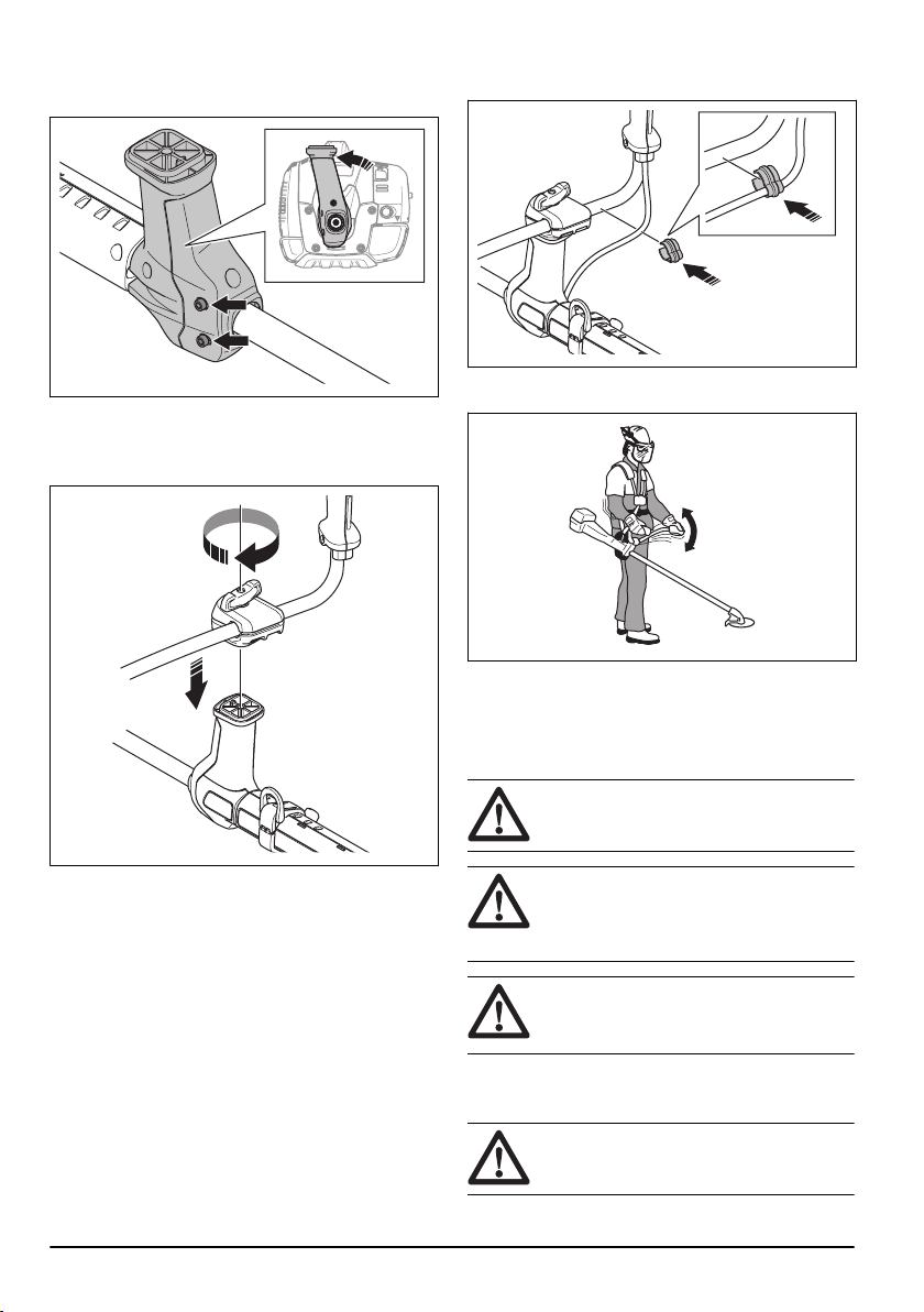
To assemble the handlebar
1. Loosen the 2 screws on the handlebar bracket.
2. Put the handlebar bracket into position on the shaft.
Tighten the 2 screws on the handlebar bracket.
3. Attach the brackets together with the handlebar on
the handlebar bracket.
4. Tighten the handle adjustment knob slightly. Do not
tighten the handle adjustment knob fully.
5. Remove the clip from the handlebar. Put the tube
into the clip and attach it to the handlebar.
6. Adjust the handlebar to put the product in a correct
work position.
7. Tighten the handle adjustment knob fully.
To assemble the cutting equipment
The cutting equipment includes a cutting attachment and
a cutting attachment guard.
WARNING: Use protective gloves.
WARNING: Always use the cutting
attachment guard that is recommended for
the cutting attachment. See
Accessories on
page 24
.
WARNING: An incorrectly attached
cutting attachment can result in injury or
death.
To attach a blade guard, grass blade and
grass cutter
CAUTION: Make sure that the guard
extension is removed.
10 1818 - 006 - 20.12.2022
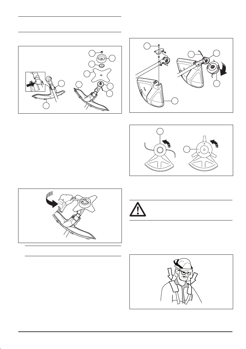
Note: Use the recommended blade guard. Refer to
Accessories on page 24
.
1. Install the blade guard to the shaft. Attach the blade
guard with the bolt (L).
G
E
F
D
B
C
A
A
L
2. Attach the drive disc (B) to the output shaft.
3. Turn the output shaft until 1 of the holes in the drive
disc aligns with the hole in the gear housing.
4. Put the locking pin or hex key (C) into the hole to
lock the shaft.
5. Put the blade (D), support flange (E) and support
cup (F) on the output shaft.
6. Install the nut (G). Use the combination wrench and
tighten the nut to torque 35-50 Nm. Hold the shaft of
the combination wrench as near the blade guard as
possible.
7. To tighten the nut, turn the combination wrench in
the opposite direction to the direction of rotation.
Note:
Left hand thread.
To assemble and disassemble the cutting
attachment guard and trimmer head
1. Attach the correct cutting attachment guard (A) for
the trimmer head. Refer to
Accessories on page 24
.
2. Put the cutting attachment guard onto the fitting on
the shaft.
3. Attach the cutting attachment guard with the bolt (B).
4. Install the drive disc (C) on the output shaft.
5. Turn the output shaft until one of the holes in the
drive disc aligns with the related hole in the gear
housing.
6. Put the locking pin (D) in the hole to lock the shaft.
B
C
E
A
D
7. Turn the cutting equipment (E) in the opposite
direction from which the cutting equipment rotate.
E
E
8. To disassemble, follow the instructions in the
opposite sequence.
To adjust the harness
WARNING:
The product must always
be correctly attached to the harness. Do not
use a defective harness.
1. Put on the harness.
2. Connect the product to the harness.
3. Adjust the harness for the best work position.
4. Adjust the side straps to make the product weigh
equally on your shoulders.
5. Adjust the harness until the cutting attachment is
parallel to the ground.
1818 - 006 - 20.12.2022
11
6. Let the cutting attachment lightly touch the ground.
Adjust the harness clamp to balance the product
correctly.
Note: If you use a grass blade, it must balance
approximately 10 cm /4 in above the ground.
Operation
WARNING: Read and understand the
safety chapter before you operate the
product.
Introduction
WARNING: Before you operate the
product, you must read and understand the
safety chapter.
Fuel
This product has a two-stroke engine.
CAUTION: Incorrect type of fuel can
result in engine damage. Use a mixture of
gasoline and two-stroke oil.
Premixed fuel
• Use Husqvarna premixed alkylate fuel for best
performance and extension of the engine life. This
fuel contains less harmful chemicals compared
to regular fuel, which decreases harmful exhaust
fumes. The quantity of remains after combustion is
lower with this fuel, which keeps the components of
the engine more clean.
To mix fuel
Gasoline
• Use good quality unleaded gasoline with a maximum
of 10% ethanol contents.
CAUTION:
Do not use gasoline with
an octane grade less than 90 RON/87
AKI. Use of a lower octane grade can
cause engine knocking, which causes
engine damages.
Two-stroke oil
• For best results and performance use Husqvarna
two-stroke oil.
• If Husqvarna two-stroke oil is not available, use a
two-stroke oil of good quality for air-cooled engines.
Speak to your servicing dealer to select the correct
oil.
CAUTION:
Do not use two-stroke
oil for water-cooled outboard engines,
also referred to as outboard oil. Do not
use oil for four-stroke engines.
To mix gasoline and two-stroke oil
Gasoline, liter Two-stroke oil, liter
2% (50:1)
5 0.10
10 0.20
15 0.30
20 0.40
CAUTION: Small errors can influence
the ratio of the mixture drastically when you
mix small quantities of fuel. Measure the
quantity of oil carefully and make sure that
you get the correct mixture.
1. Fill half the quantity of gasoline in a clean container
for fuel.
2. Add the full quantity of oil.
3. Shake the fuel mixture.
4. Add the remaining quantity of gasoline to the
container.
5. Carefully shake the fuel mixture.
CAUTION: Do not mix fuel for more
than 1 month at a time.
12 1818 - 006 - 20.12.2022
To fill the fuel tank
WARNING: Obey the procedure that
follows for your safety.
1. Stop the engine and let the engine become cool.
2. Clean the area around the fuel tank cap.
3. Shake the container and make sure that the fuel is
fully mixed.
4. Remove the fuel tank cap slowly to release the
pressure.
5. Fill the fuel tank.
CAUTION: Make sure that there is
not too much fuel in the fuel tank. The
fuel expands when it becomes hot.
6. Tighten the fuel tank cap carefully.
7. Clean fuel spillage on and around the product.
8. Move the product 3 m/10 ft or more away from the
refueling area and fuel source before you start the
engine.
Note:
To see where the fuel tank is on your product,
refer to
Product overview on page 2
.
To start and stop
Before you operate the product
• Examine the work area to make sure that you know
the type of terrain, the slope of the ground and if
there are obstacles such as stones, branches and
ditches.
• Do an overhaul inspection of the product.
• Do the safety inspections, maintenance and
servicing that are given in this manual.
• Make sure that all covers, guards, handles and the
cutting equipment are correctly attached and not
damaged.
• Make sure that there are no cracks at the bottom of
the grass blade teeth or by the center hole of the
blade. Replace the blade if it is damaged.
• Examine the support flange for cracks. Replace the
support flange if it is damaged.
• Make sure that the locknut can not be removed by
hand. If you can remove it by hand, it does not
lock the cutting attachment sufficiently and you must
replace it.
• Examine the trimmer head and trimmer guard for
damages or cracks. Replace the trimmer head and
trimmer guard if they have been hit or if they have
cracks.
1818 - 006 - 20.12.2022
13
Connectivity
This product is prepared for connectivity and has a
location for installation of a Husqvarna Connectivity
Device. When the Husqvarna connectivity device
is installed, the product has
Bluetooth
®
wireless
technology and can use Husqvarna Fleet Services
™
to
connect to mobile devices. This enables more functions.
Husqvarna Connect
Husqvarna Connect is a free app for your mobile device.
The Husqvarna Connect app gives extended functions
for your Husqvarna product.
• Extended product information.
• Information about, and help with, product parts and
servicing.
To start to use Husqvarna Connect
1. Download the Husqvarna Connect app on your
mobile device.
2. Register in the Husqvarna Connect app.
3. Follow the instruction steps in the Husqvarna
Connect app to connect and register the product.
Note: Husqvarna Connect app is not available for
download in all markets. Speak to your servicing
dealer for more information.
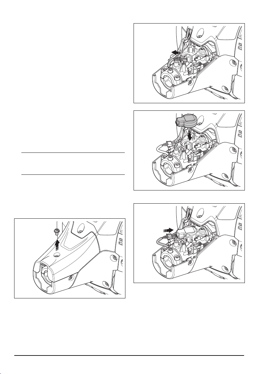
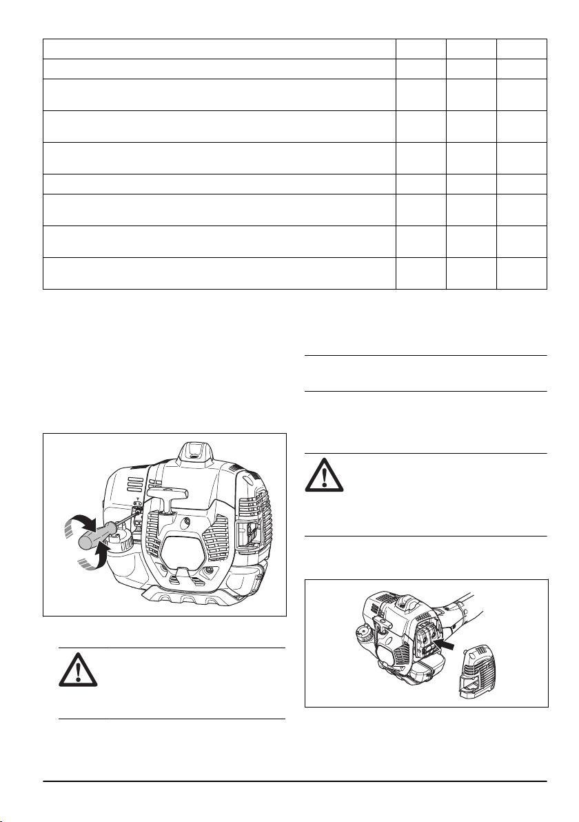
To install the Husqvarna connectivity device
Do the steps that follow to install the Husqvarna
connectivity device. For more information about
the Husqvarna connectivity device, refer to
www.husqvarna.com.
1. Remove the screw and open the plastic cover.
2. Remove the connector.
3. Install the Husqvarna connectivity device.
4. Install the connector to the Husqvarna connectivity
device.
14
1818 - 006 - 20.12.2022
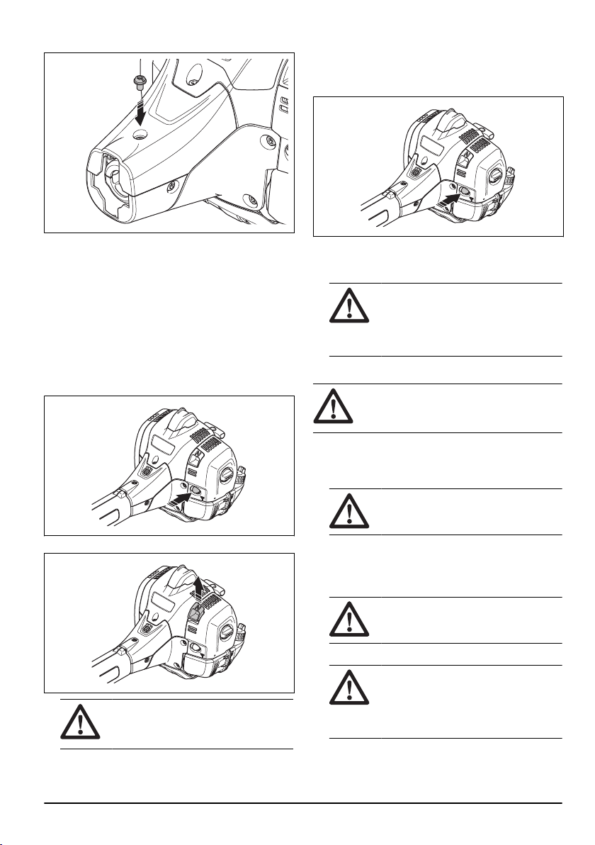
5. Install the plastic cover and tighten the screw.
Husqvarna Fleet Services
™
Husqvarna Fleet Services
™
is a cloud solution that
gives the commercial fleet manager an overview of all
products. It is also possible for the fleet managers to
get remote access to information about the product.
For more information about Husqvarna Fleet Services
™
,
refer to www.husqvarna.com.
To prepare a cold engine for start
1. Push the air purge bulb again and again until fuel
starts to fill the bulb. It is not necessary to fill the air
purge bulb fully.
2. Move the choke control up into choke position.
WARNING:
The cutting attachment
starts to rotate immediately when you
start the engine with the choke.
To prepare a warm engine for start
1. Push the air purge bulb again and again until fuel
starts to fill the bulb. It is not necessary to fill the air
purge bulb fully.
2. Pull the starter rope handle until the engine starts.
Push the throttle trigger slowly to increase the speed
gradually.
CAUTION: Do not pull the starter
rope to full extension. Do not let go of
the starter rope handle when the starter
rope is fully extended. This can cause
damage to the product.
To start the product
WARNING: Read the warning
instructions in the safety chapter before you
start the product (refer to
Safety on page 4
).
1. Use protective gloves.
2. Hold the body of the product on the ground with your
left hand.
CAUTION: Do not use your feet!
3. Hold the starter rope handle with your right hand.
4. Slowly pull out the starter rope with your right hand
until you feel some resistance (the starter pawls
grip).
WARNING:
Do not twist the starter
rope around your hand.
5. Pull the cord quickly and with power.
CAUTION:
Do not pull the starter
rope all the way out and do not let go off
the starter rope handle when the starter
rope is fully extended. This can cause
damage to the product.
6. Pull the starter rope until the engine starts or for a
maximum of 5 times.
1818 - 006 - 20.12.2022
15
7. Reset the choke when the engine starts or after you
pull the starter rope 5 times.
8. If it is necessary, pull the starter rope again and
again until the engine starts.
9. Let the engine run for 10 seconds.
10. Operate the throttle gradually.
11. Make sure the engine runs smoothly.
Note: If the engine stops, do the procedure again.
To stop the engine
1. Push the throttle trigger to the idle position.
2. Move the stop switch to the stop position.
To operate the grass trimmer
CAUTION: Make sure that you slow the
engine to idle speed after each operation. A
long period at full throttle without a load on
the engine can cause damage to the engine.
Note: Clean the cover of the trimmer head when
you attach a new trimmer line to prevent vibrations.
Examine other parts of the trimmer head and clean if
it is necessary.
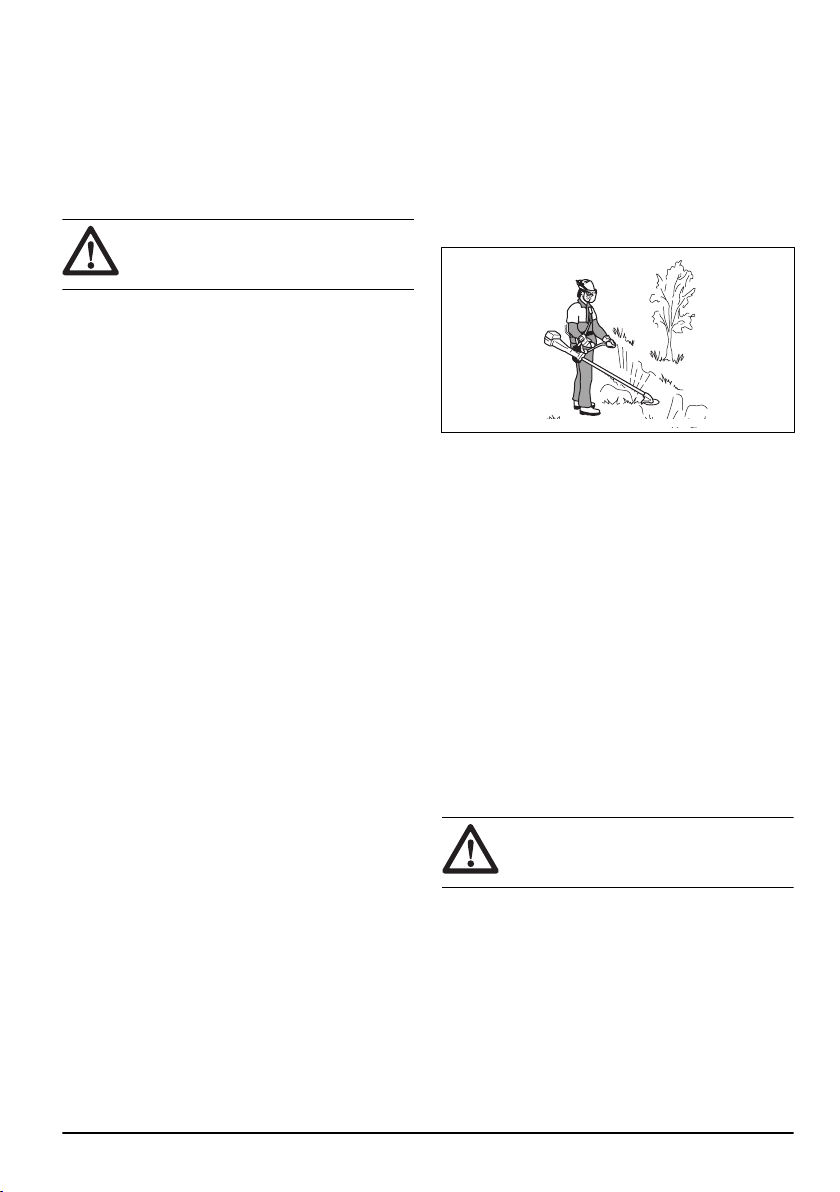
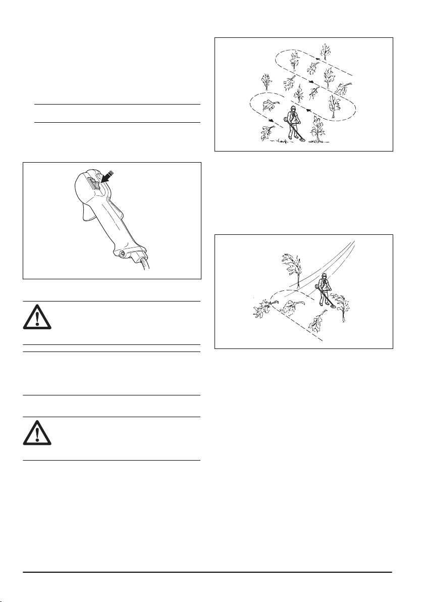
General work instructions
WARNING:
Be careful when you cut a
tree that is in tension. It can spring back to
its normal position before or after the cut and
hit you or the product, and cause injury.
• Clear an open space at one end of the work area,
and start the work from there.
• Move in a regular pattern across the work area.
• Move the product fully to the left and right, to clear a
width of 4–5 m (13-16 ft) on each turn.
• Clear a length of 75 m (250 ft) before you turn and
go back. Move the fuel can along with you as you
continue.
• Move in a direction where you do not go across
ditches and obstacles more than necessary.
• Move in a direction where the wind makes the cut
vegetation fall in the cleared area.
• Move along slopes, not up and down.
Blade thrust
A blade thrust is when the product moves to the side
quickly and with force. A blade thrust occurs when the
grass blade or saw blade hits or catches on an object
that cannot be cut. A blade thrust can eject the product
or operator in all directions. There is a risk of injury to
the operator and bystanders.
The risk increases in areas where it is not easy to see
the material that is cut.
Do not cut with the area of the blade that is shown in
black. The speed and movement of the blade can cause
16
1818 - 006 - 20.12.2022
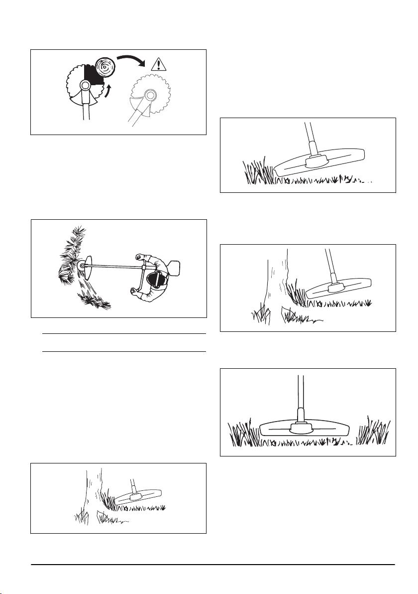
blade thrust. The risk increases with the thickness of the
branch that is cut.
To clear grass with a grass blade
1. Keep your feet apart during operation of the product.
Make sure feet are tightly against the ground.
2. Put the support cup lightly on the ground. This
prevents the blade from touching the ground.
3. Use a sideway movement from right to left for a clear
stroke. Use the left side of the blade (between 8 and
12 o'clock) to cut.
4. Angle the blade to the left when you clear grass.
Note:
The grass collects easily in a line.
5. Use a sideway movement from left to right for the
return stroke.
6. Do the work rhythmically.
7. Move forward and keep feet tightly against the
ground.
8. Stop the engine.
9. Remove the product from the clip on the harness.
10. Put the product on the ground.
11. Collect the cut material.
To clear
To achieve the best results:
• Hold the trimmer so that the trimmer head is just
above the ground.
• Tilt the trimmer head at a slight angle.
• Let the end of the trimmer line strike the ground
around objects.
To trim the grass
1. Hold the trimmer head immediately above the
ground at an angle. Do not push the trimmer line
into the grass.
2. Decrease the length of the trimmer line by 10-12
cm / 4-4.75 in.
3. Decrease the engine speed to decrease the risk of
damage to plants.
4. Use 80 % throttle when you cut grass near objects.
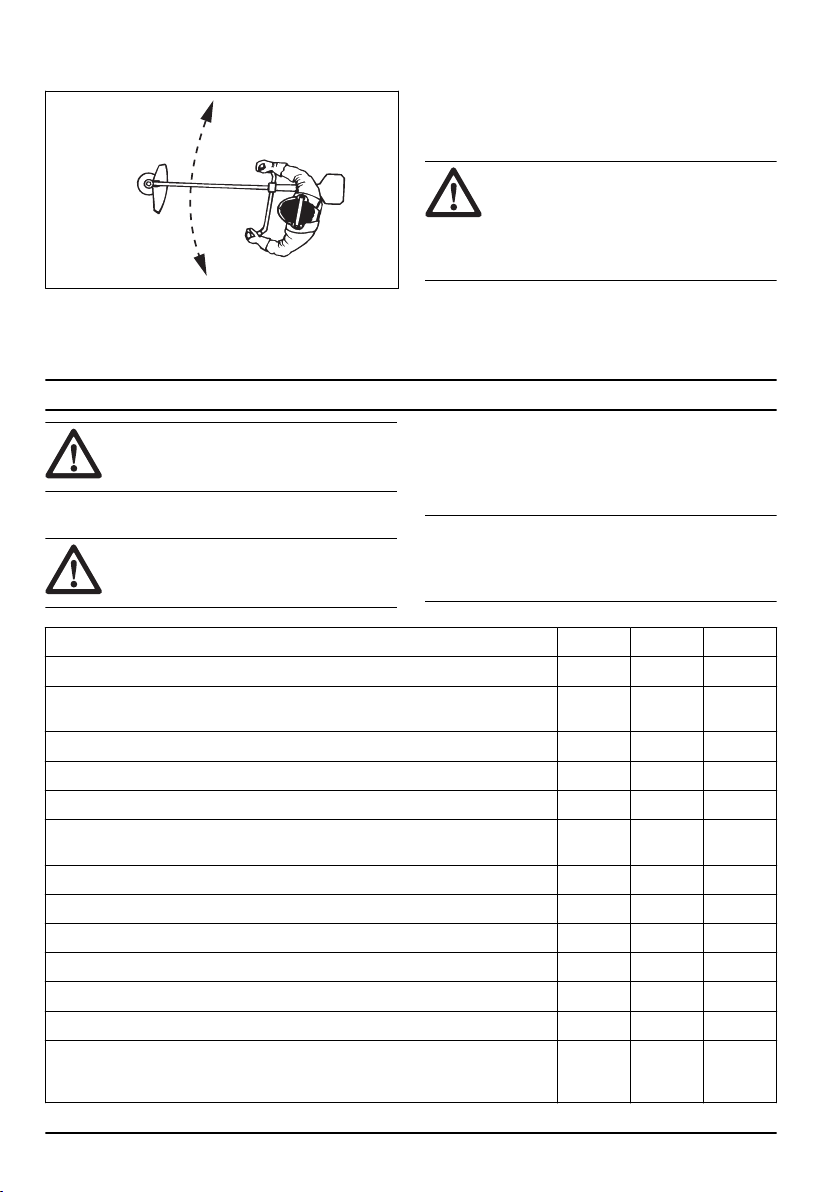
To cut the grass
1. Make sure that the trimmer line is parallel to the
ground when you cut.
2. Do not push the trimmer head to the ground. The
ground and the product can be damaged.
3. Do not let the trimmer head touch the ground
continuously, it can cause damage to the trimmer
head.
1818 - 006 - 20.12.2022
17
4. Use full throttle when you move the product from
side to side to cut grass.
To sweep the grass
The airflow from the rotating trimmer line can be used to
remove cut grass from an area.
1. Hold the trimmer head and its trimmer line parallel to
the ground and above the ground.
2. Apply full throttle.
3. Move the trimmer head from side to side and sweep
the grass.
WARNING: Clean the trimmer head
cover each time you assemble new trimmer
line to prevent unbalance and vibrations in
the handles. Also do a check of the other
parts of the trimmer head and clean it if
necessary.
Maintenance
WARNING: Read and understand the
safety chapter before you clean, repair or do
maintenance on the product.
Introduction
WARNING: Before you do any
maintenance work you must read and
understand the safety chapter.
Maintenance schedule
The following is a list of the maintenance steps that
must be performed on the product. Most of the items are
described in
Maintenance on page 18
Note: The user must only carry out the maintenance
and service work described in this operator's manual.
More extensive work must be carried out by an
authorized service workshop.
Maintenance Daily Weekly Monthly
Clean the external surface. X
Make sure that the throttle trigger lock and the throttle works correctly from a
safety point of view.
X
Do a check of the stop switch to make sure that it works correctly. X
Make sure that the cutting attachment does not rotate at idle speed. X
Clean the air filter. Replace if necessary. X
Examine the cutting attachment guard for damages and cracks. Replace the
guard if it has been exposed to impact or is cracked.
X
Examine the trimmer head for damages and cracks. Replace if damaged. X
Make sure that the screws and nuts are tight. X
Examine the engine, the fuel tank and the fuel lines for leaks. X
Clean the cooling system. X
Examine the starter and the starter rope for damages. X
Examine the vibration damping elements for damages and cracks. X
Clean the outside of the spark plug. Remove it and do a check of the electrode
gap. Adjust the gap to the correct distance (see,
Technical data on page 23
) or
replace the spark plug. Make sure that the spark plug is fitted with a suppressor.
X
18 1818 - 006 - 20.12.2022
Maintenance Daily Weekly Monthly
Clean the outside of the carburettor and the space around it. X
Do a check of the bevel gear to make sure that it is filled 3/4 with lubricant. Use
special grease to fill if necessary.
X
Clean or replace the spark arrestor mesh on the muffler (only applies to mufflers
without a catalytic converter).
X
Do a check of the fuel filter for contamination and the fuel hose for cracks or
other defects. Replace if necessary.
X
Do a check of all cables and connections. X
Do a check of the clutch, clutch springs and the clutch drum for wear. Replace if
necessary by an autorized service workshop.
X
Replace the spark plug. Make sure that the spark plug is fitted with a suppres-
sor.
X
Check and clean the spark arrestor mesh on the muffler (only applies to mufflers
without a catalytic converter).
X
To adjust the idle speed
Your Husqvarna product is made to specifications that
decrease harmful emissions.
1. Make sure that the air filter is clean and the air filter
cover is attached before you adjust the idle speed.
2. Adjust the idle speed with the idle speed screw
which is identified with "T" mark.
a) Turn the idle speed screw clockwise until the
cutting attachment starts to rotate.
b) Turn the idle speed screw counterclockwise until
the cutting attachment stops.
WARNING: If the cutting
attachment does not stop when you
adjust the idle speed, speak to your
servicing dealer. Do not use the product
until it is correctly adjusted or repaired.
3. The idle speed is correct when the engine operates
smoothly in all positions. The idle speed must be
below the speed when the cutting attachment starts
to rotate.
Note: Refer to
Technical data on page 23
for the
recommended idle speed.
To do maintenance on the muffler
The muffler decreases the noise level and directs the
exhaust gases away from the operator.
WARNING: Mufflers that have catalytic
converters get very hot during operation and
will stay hot for some time after you stop the
product. This also applies at idle speed. If
you touch the product it can result in burns
to the skin. Think about of the risk of fire.
1. Stop the product and let it cool down.
2. Remove the cover to the muffler.
1818 - 006 - 20.12.2022 19
3. Remove the screw holding the spark arrestor mesh.
4. Clean the spark arrestor mesh if it is blocked or
replace it if it is damaged.
CAUTION: The spark arrestor mesh
must be replaced if it is damaged. Do not
use a product if the spark arrestor mesh on
the muffler is missing or defective.
CAUTION: If the spark arrestor mesh
is frequently blocked it can be a sign that
performance of the catalytic converter is
decreased. Turn to your servicing dealer
to examine the muffler. A blocked spark
arrestor mesh will cause overheating and
result in damage to the cylinder and piston.
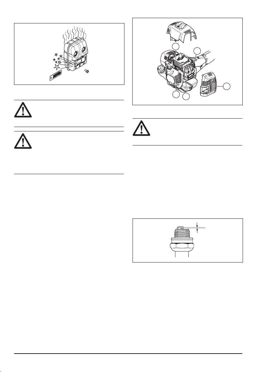
Cooling system
The product has a cooling system to keep the operation
temperature as low as possible.
Clean the components of the cooling system with a
brush weekly or more frequently in rougher conditions.
A dirty or blocked cooling system makes the product too
hot which causes damage to the piston and cylinder.
The cooling system has the following components:
1. Air intake on the starter.
2. Fins on the flywheel.
3. Cooling fins on the cylinder.
4. Cylinder cover.
5. Muffler cover.
6. Muffler plate.
5
6
1
1
2
To examine the spark plug
CAUTION: Always use the
recommended spark plug type. Incorrect
spark plug type can cause damage to the
product.
• Examine the spark plug if the engine is low on
power, is not easy to start or does not operate
correctly at idle speed.
• To decrease the risk of unwanted material on the
spark plug electrodes, obey these instructions:
a) Make sure that the idle speed is correctly
adjusted.
b) Make sure that the fuel mixture is correct.
c) Make sure that the air filter is clean.
• If the spark plug is dirty, clean it and make sure that
the electrode gap is correct, refer to
Technical data
on page 23
.
• Replace the spark plug if it is necessary.
Air filter
Remove dust and dirt from the air filter to keep it clean
and prevent these problems:
• Carburetor malfunctions.
• Problems when you start the product.
• Loss of engine power.
• Increased wear to engine parts.
• Too much fuel consumption.
20
1818 - 006 - 20.12.2022
To clean the air filter
CAUTION: An air filter that is damaged,
very dirty, or soaked with fuel must always
be replaced.
Clean the air filter from dirt and dust regularly. This
prevents carburetor malfunctions, starting problems,
loss of engine power, wear to engine parts and more
fuel consumption than usual.
If you use an air filter for a long time, it cannot be fully
cleaned. Replace the air filter with a new one at regular
intervals. Refer to
Maintenance schedule on page 18
.
1. Move the choke lever up to close the choke valve.
2. Remove the air filter cover and the air filters.
3. Clean the air filters with warm soap water.
4. Replace the air filters if they cannot be fully cleaned.
Always replace a damaged air filter.
5. Clean the inner surface of the air filter cover. Use
compressed air or a brush.
6. Do a check of the rubber seal on the air filter.
Replace the air filter if the rubber seal is damaged.
7. Make sure that the air filter is dry before you install it.
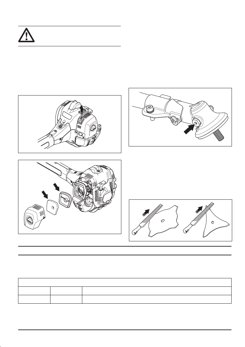
Bevel gear
The bevel gear is filled with the right quantity of grease
at the factory. But, before you use the product, make
sure that the bevel gear is 3/4 full with grease. Use
Husqvarna special grease.
The grease in the bevel gear does not need to be
changed unless repairs are carried out.
To sharpen grass cutters and grass
blades
1. Sharpen grass cutters and grass blades with a
single-cut flat file.
2. Sharpen all edges of the grass cutters and blades
equally to keep the balance.
Troubleshooting
Troubleshooting
Starting failure
Check Possible cause Solution
Stop Switch Stop position Set the stop switch to the start position.
1818 - 006 - 20.12.2022 21

Starting failure
Check Possible cause Solution
Starter pawls Binding pawls Adjust or replace the pawls.
Clean around the pawls.
Speak to an approved servicing dealer.
Fuel tank Incorrect fuel
type.
Drain it and use correct fuel.
Carburetor Adjustment of
the idle speed.
Adjust the idle speed with the T screw.
Spark (no
spark)
Spark plug dirty
or wet.
Make sure that the spark plug is dry and clean.
Spark plug
clearance in-
correct.
Clean the spark plug. Check that the electrode gap is correct. Make sure that the
spark plug is installed with a supressor.
Refer to technical data for correct electrode gap.
Spark plug Spark plug
loose.
Tighten the spark plug.
Fuel filter Clogged fuel fil-
ter.
Replace the fuel filter.
Engine starts but does not stay running
Check Possible cause Solution
Fuel tank Incorrect fuel
type.
Drain it and use correct fuel.
Carburetor Engine will not
idle correctly.
Speak to your servicing dealer.
Air filter Clogged air fil-
ter.
Clean the air filter.
Fuel filter Clogged fuel fil-
ter.
Replace the fuel filter.
Transportation and storage
• Keep equipment safe during transportation to
prevent damage and accidents.
• Keep the product and equipment in a dry and frost-
proof area.
• Clean the product.
• Replace or repair damaged components.
• Use the correct protective cover on the product that
does not keep moisture.
• Keep the product tightly attached during transport.
• When you store the product for long periods the fuel
tank must be emptied
22 1818 - 006 - 20.12.2022

Technical data
Technical data
525RX Mark II 525RXT Mark II
Engine
Cylinder displacement, cm
3
25.4 25.4
Idle speed, rpm 3000 3000
Speed of output shaft, rpm 6500/7500 6500/7500
Catalytic converter muffler Yes Yes
Maximum engine power acc. to ISO 8893, kW/hp @ rpm 1.0/1.34 @ 8500 1.0/1.34 @ 8500
Ignition system
Spark plug Husqvarna HQT-2 Husqvarna HQT-2
Electrode gap, mm 0.5 0.5
Fuel and lubrication system
Fuel tank capacity, l/cm
3
0.66/660 0.66/660
Weight
Weight, kg 5.5 5.8
Noise emissions
1
Sound power level, measured, dB (A) 106 106
Sound power level, guaranteed LWA, dB (A) 108 108
Sound levels
Equivalent sound pressure level at the operator’s ear,
measured according to EN ISO 11806 and ISO 22868
2
Equipped with trimmer head (original), dB (A) 94 94
Equipped with grass blade (original), dB (A) 94 96
Vibration levels
Equivalent vibration levels (a
hv,eq
) at handles, measured
according to EN ISO 11806 and ISO 22867
3
Equipped with trimmer head (original), left/right, m/s
2
2.3/1.8 2.3/1.8
Equipped with grass blade (original), left/right, m/s
2
2.0/2.5 2.0/2.5
1
Noise emissions in the environment measured as sound power (L
WA
) in conformity with EC directive
2000/14/EC. Reported sound power level for the machine has been measured with the original cutting
attachment that gives the highest level. The difference between guaranteed and measured sound power
is that the guaranteed sound power also includes dispersion in the measurement result and the variations
between different machines of the same model according to Directive 2000/14/EC.
2
Reported data for noise pressure level has a typical statistical dispersion (standard deviation) of 1 dB (A).
3
Reported data for vibration level has a typical statistical dispersion (standard deviation) of 1 m/s
2
.
1818 - 006 - 20.12.2022 23

Accessories
Accessories
Approved accessories Accessory type Cutting attachment guard, art. no.
Grass blade/grass cutter Grass 255-4 1" (Ø 255 4 teeth) 588 11 79-01
Grass blade 255-3 (Ø 255 3 teeth) 588 11 79-01
Plastic blades Tricut Ø 300 mm (Separate blades
have part number 531 07 77-15)
588 11 79-01
Trimmer head T25 (Ø 2.0 - 2.7 mm cord) 588 54 37-01 / 588 11 79-01
T35, T35x (Ø 2.4 - 3.0 mm cord) 588 54 37-01 / 588 11 79-01
Superauto II 588 54 37-01 / 588 11 79-01
Alloy (up to Ø 2.4 mm cord) 588 54 37-01 / 588 11 79-01
24 1818 - 006 - 20.12.2022

Declaration of Conformity
EU Declaration of Conformity
We, Husqvarna AB, SE-561 82 Huskvarna, Sweden, tel:
+46-36-146500, declare on our sole responsibility that
the product:
Description Brush cutters
Brand Husqvarna
Type / Model 525RX Mark II, 525RXT Mark II
Identification Serial numbers dating from 2023 and onwards
complies fully with the following EU directives and
regulations:
Regulation Description
2006/42/EC "relating to machinery"
2014/30/EU "relating to electromagnetic compatibility"
2000/14/EC "relating to the noise emissions in the environment"
2011/65/EU
“on the restriction of the use of certain hazardous substances in electrical and electronic
equipment ”
and that the following standards and/or technical
specifications are applied: EN ISO 12100:2021,
CISPR12:2007+A1:2009, EN ISO 14982:2009, EN ISO
11806-1:2011, EN IEC 63000:2018
RISE SMP Svensk Maskinprovning AB, Box 7035,
SE-750 07 Uppsala, Sweden has performed voluntary
type examination on behalf of Husqvarna AB.
Certificate Number: SEC/22/2574
RISE SMP Svensk Maskinprovning AB, Box 7035,
SE-750 07 Uppsala, Sweden, has also verified
agreement with appendix V of the council's directive
2000/14/EG.
For information relating to noise emissions, refer to
Technical data on page 23
.
Huskvarna, 2022-06-08
Stefan Holmberg, R&D Director, Technology
Management, Husqvarna AB
Responsible for technical documentation
1818 - 006 - 20.12.2022 25

UK Declaration of Conformity
We, Husqvarna AB, SE-561 82 Huskvarna, Sweden, tel:
+46-36-146500, declare on our sole responsibility that
the product:
Description Brush cutters
Brand Husqvarna
Type / Model 525RX Mark II, 525RXT Mark II
Identification Serial numbers dating from 2023 and onwards
complies fully with the following UK regulations:
Description
The Supply of Machinery (Safety) Regulations 2008
Electromagnetic Compatibility Regulations 2016
The Noise Emission in the Environment by Equipment for use Outdoors Regulations 2001, Schedule 8
The Restriction of the Use of Certain Hazardous Substances in Electrical and Electronic Equipment Regulations
2012
and that the following standards and/or technical
specifications are applied: EN ISO 12100:2021,
CISPR12:2007+A1:2009, EN ISO 14982:2009, EN ISO
11806-1:2011, EN IEC 63000:2018
For information relating to noise emissions, refer to
Technical data on page 23
.
Huskvarna, 2022-06-08
Stefan Holmberg, R&D Director, Technology
Management, Husqvarna AB
Responsible for technical documentation
UK Importer:
Husqvarna UK Ltd
Preston Road, Co. Durham
DL5 6UP
26 1818 - 006 - 20.12.2022

1818 - 006 - 20.12.2022 27

www.husqvarna.com
Original instructions
1141712-26
2022-12-22