

525LST, 525RS, 525RJD
EN Operator's manual 2-26
Contents
Introduction..................................................................... 2
Safety..............................................................................4
Assembly...................................................................... 10
Operation...................................................................... 15
Maintenance................................................................. 19
Troubleshooting............................................................ 23
Transportation, storage and disposal........................... 24
Technical data.............................................................. 25
Accessories.................................................................. 26
Introduction
Product description
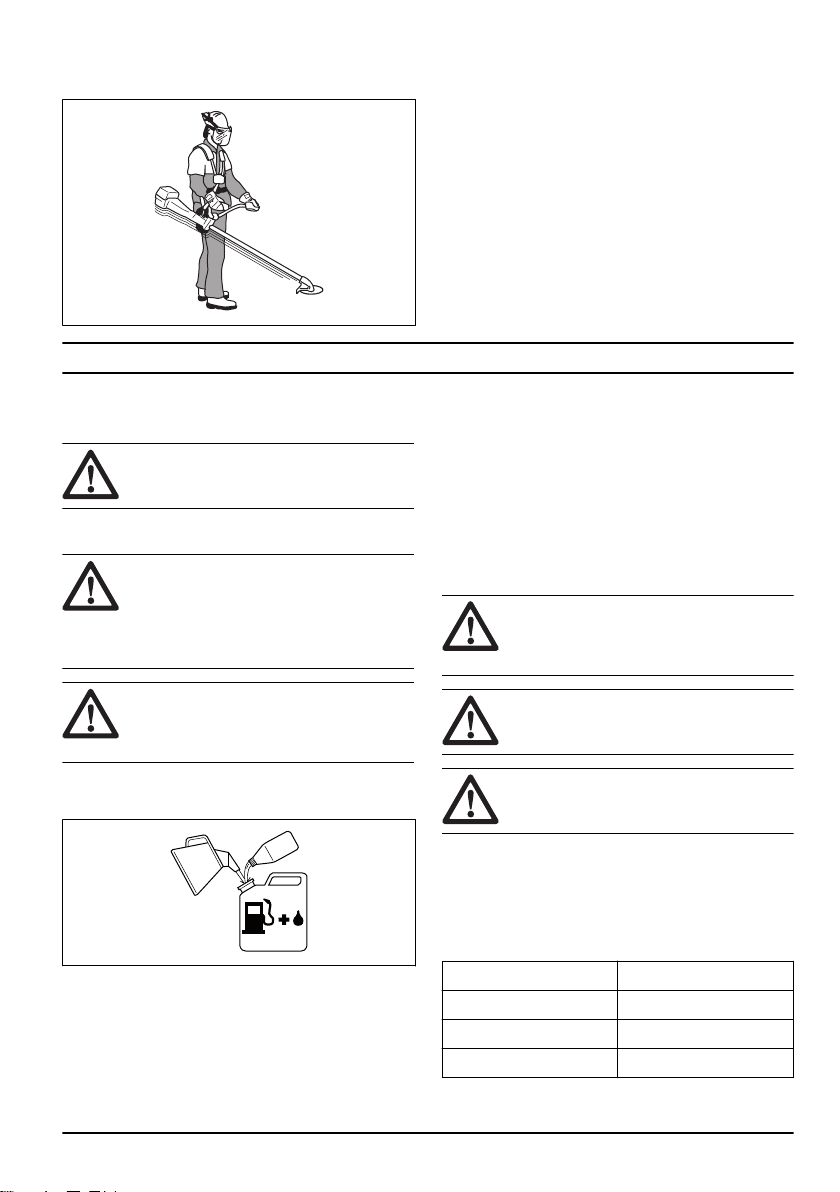
The product is a grass trimmer with a combustion
engine.
Work is constantly in progress to increase your safety
and efficiency during operation. Speak to your servicing
dealer for more information.
Intended use
The product is used with a trimmer head to cut grass.
Do not use the product for other tasks than grass
trimming and grass clearing.
Note: National regulations can set limit to the operation
of the product.
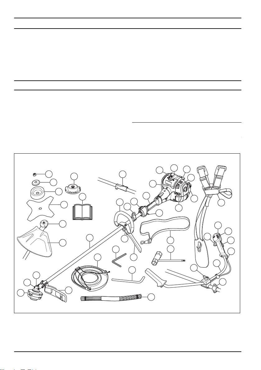
Product overview
17
18
24
25
19
4
35
26
23
11
10
12
14
13
32
8
31
7
9
30
34
29
28
15
7
8
37
6
28
32
20
36
22
27
21
33
5
4
3
2
1
16
9
1. Trimmer head
2. Grease filler cap
3. Bevel gear
4. Cutting attachment guard
5. Shaft
6. Loop handle (525LST, 525RJD)
7. Throttle trigger
8. Stop switch
2 1363 - 001 - 25.10.2019
9. Throttle trigger lockout
10. Spark plug cap and spark plug
11. Cylinder cover
12. Starter rope handle
13. Fuel tank
14. Air filter cover
15. Air purge bulb
16. Choke control
17. Locknut
18. Support flange
19. Drive disc
20. Combination wrench
21. Hex key
22. Locking pin
23. Operator's manual
24. Support cup
25. Blade
26. Shaft coupling (525RJD)
27. J-handle (525LST, 525RJD )
28. Handle adjustment
29. Suspension ring (525RS)
30. Throttle wire adjustment (525RS)
31. Start throttle button (525RS)
32. Harness
33. Transport guard
34. Handlebar (525RS)
35. Trimmer head (525LST)
36. Trimmer line (525LST)
37. Suspension ring (525LST, 525RJD)
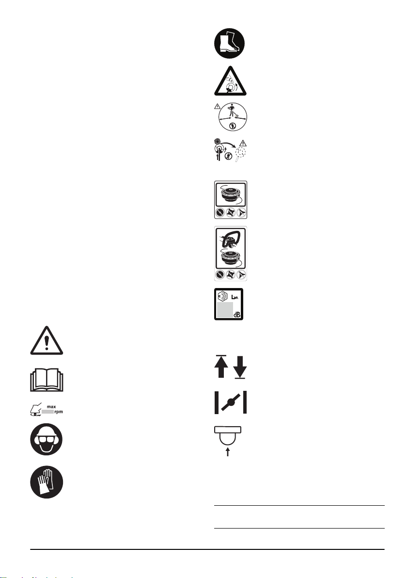
Symbols on the product
WARNING: This product can be dangerous
and cause serious injury or death to the
operator or others. Be careful and use the
product correctly.
Read the operator's manual carefully and
make sure that you understand the
instructions before use.
Maximum speed of the output shaft.
Use a protective helmet in locations where
objects can fall on you. Use approved
hearing protection. Use approved eye
protection.
Use approved protective gloves.
Use heavy-duty slip-resistant boots.
The product can cause objects to eject,
which can cause injury.
5
0
FT
1
5
m
50F
T
15 m
Keep a minimum of 15 m distance to
persons and animals during operation of the
product.
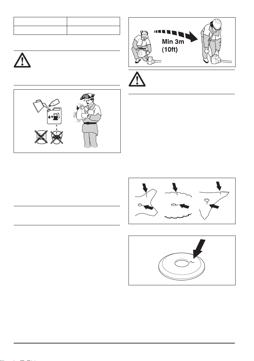
Risk of blade thrust if the cutting equipment
touches an object that it does not
immediately cut. The product can cut off
body parts.
Only use flexible cutting wire. Do not use
metal cutting attachments.
Only use flexible cutting wire. Do not use
metal cutting attachments.
Noise emissions to the environment
according to European Directive 2000/14/EC
and New South Wales legislation “Protection
of the Environment Operations (Noise
Control) Regulation 2017”. Noise emission
data can be found on the machine label and
in the Technical data chapter.
The arrows show the limit for the handle
position.
Choke.
Air purge bulb.
yyyywwxxxx
The rating plate shows the
serial number. yyyy is the
production year, ww is the
production week.
Note: Other symbols/decals on the product refer to
certification requirements for other commercial areas.
1363 - 001 - 25.10.2019 3

Product liability
As referred to in the product liability laws, we are not
liable for damages that our product causes if:
• the product is incorrectly repaired.
• the product is repaired with parts that are not from
the manufacturer or not approved by the
manufacturer.
• the product has an accessory that is not from the
manufacturer or not approved by the manufacturer.
• the product is not repaired at an approved service
center or by an approved authority.
Safety
Safety definitions
Warnings, cautions and notes are used to point out
specially important parts of the manual.
WARNING: Used if there is a risk of injury or
death for the operator or bystanders if the
instructions in the manual are not obeyed.
CAUTION: Used if there is a risk of damage
to the product, other materials or the
adjacent area if the instructions in the
manual are not obeyed.
Note: Used to give more information that is necessary in
a given situation.
General safety instructions
WARNING: Read the warning instructions
that follow before you use the product.
• A clearing saw, brushcutter or trimmer can be
dangerous if used carelessly or incorrectly and can
cause serious injury or death to the operator or
others. It is extremely important that you read and
understand the contents of this operator’s manual.
• Under no circumstances may the design of the
product be modified without the permission of the
manufacturer. Never use a product that has been
modified in any way from its original specification
and always use original accessories. Non-authorized
modifications and/or accessories can result in
serious personal injury or the death of the operator
or others.
• The inside of the muffler contain chemicals that may
be carcinogenic. Avoid contact with these elements
in the event of a damaged muffler.
• This product produces an electromagnetic field
during operation. This field may under some
circumstances interfere with active or passive
medical implants. To reduce the risk of serious or
fatal injury, we recommend persons with medical
implants to consult their physician and the medical
implant manufacturer before operating this product.
Safety instructions for operation
WARNING: Read the warning instructions
that follow before you use the product.
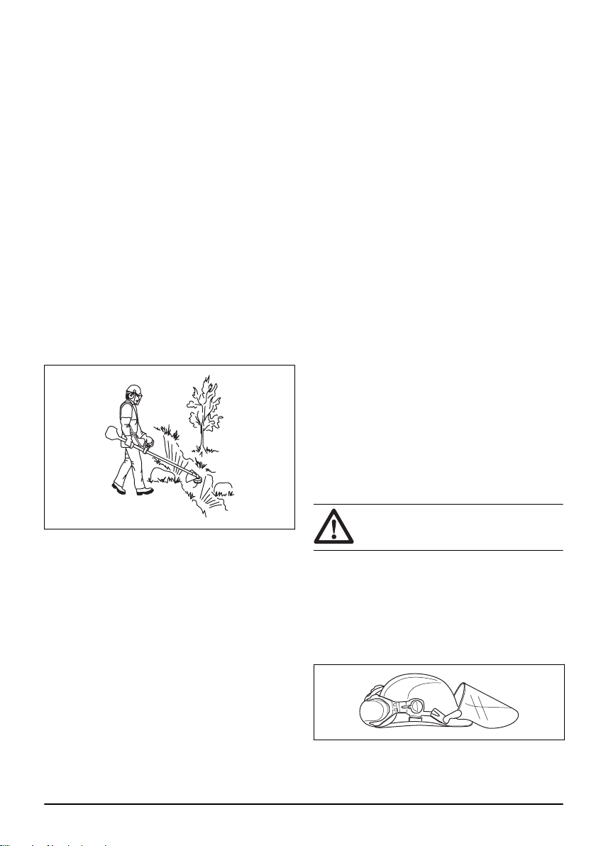
• You must understand the difference between grass
clearing and grass trimming before use.
• If you encounter a situation where you are uncertain
how to proceed you should ask an expert. Contact
your dealer or your service workshop. Avoid all
usage which you consider to be beyond your
capability.
• Never use a product that is faulty. Carry out the
safety checks, maintenance and service instructions
described in this manual. Some maintenance and
service measures must be carried out by trained and
qualified specialists. Refer to
Maintenance on page
19
.
• All covers, guards and handles must be fitted before
you start the product. Ensure that the spark plug cap
and ignition lead are undamaged to avoid the risk of
electric shock.
• Never use the product if you are fatigued, while
under the influence of alcohol or drugs, medication
or anything that could affect your vision, alertness,
coordination or judgement.
• Do not use the product in bad weather such as
dense fog, heavy rain, strong wind, intense cold,
etcetera. Working in bad weather is tiring and often
brings added risks, such as icy ground,
unpredictable felling direction, etcetera.
• The only accessories you can operate with this
engine unit are the cutting attachments that we
recommend. Refer to
Accessories on page 26
.
• Never allow children to use or be in the vicinity of the
product. As the product is equipped with a spring-
loaded start/stop switch and can be started by low
speed and force on the starter handle, even small
children under some circumstances can produce the
force necessary to start the product. This can mean
a risk of serious personal injury. Therefore remove
the spark plug cap when the product is not under
close supervision.
• Running an engine in a confined or badly ventilated
area can result in death due to asphyxiation or
carbon monoxide poisoning.
4
1363 - 001 - 25.10.2019
• The complete clutch cover and shaft must be fitted
before the product is started, otherwise the clutch
can come loose and cause personal injury.
• Ensure that no people or animals come closer than
15 m while you work. When several operators are
working in the same area the safety distance should
be at least 15 m. Otherwise there is a risk of serious
personal injury. Stop the product immediately if
anyone approaches. Never swing the product
around without first checking behind you to make
sure that noone is within the safety zone.
• Ensure that people, animals or other things can not
affect your control of the product or that they do not
come in contact with the cutting attachment or loose
objects that are thrown out by the cutting
attachment. However, do not the product unless you
are able to call for help in the event of an accident.
• Always inspect the working area. Remove all loose
objects such as stones, broken glass, nails, steel
wire, string, etcetera, that could be thrown out or
become wrapped around the cutting attachment.
• Make sure that you can move and stand safely.
Check the area around you for possible obstacles
(roots, rocks, branches, ditches, etcetera) in case
you have to move suddenly. Take great care when
you work on sloping ground.
• Keep a good balance and a firm foothold at all times.
Do not overreach.
• Always hold the product with both hands. Hold the
product on the right side of your body.
• Keep the cutting attachment below waist level.
• Switch off the engine before you move to another
area. Fit the transportation guard before you carry or
transport the equipment any distance.
• Never put the product down with the engine running
unless you have it in clear sight.
• Stop the engine and cutting equipment before you
remove material that has wound around the blade
shaft. Neither the operator of the product nor anyone
else may attempt to remove the cut material while
the engine is running or the cutting equipment is
rotating, as this can result in serious injury. The
bevel gear can get hot during use and may remain
so for a while afterwards. You could get burnt if you
touch it.
• Watch out for thrown objects. Always wear approved
eye protection. Never lean over the cutting
attachment guard. Stones, rubbish, etcetera, can be
thrown up into the eyes which can cause blindness
or serious injury.
• Sometimes branches or grass get caught between
the guard and cutting attachment. Always stop the
engine before you clean the product.
• Always slow the engine to idle speed after each
working operation. Long periods at full throttle
without any load on the engine can lead to serious
engine damage.
• Listen out for warning signals or shouts when you
wear hearing protection. Always remove your
hearing protection as soon as the engine stops.
• Overexposure to vibration can lead to circulatory
damage or nerve damage in people who have
impaired circulation. Contact your doctor if you
experience symptoms of overexposure to vibration.
These symptoms include numbness, loss of feeling,
tingling, pricking, pain, loss of strength, changes in
skin color or condition. These symptoms normally
appear in the fingers, hands or wrists.
• Do not use a product with a damaged spark plug
cap.
• Do not use a product with a defective muffler.
• Keep all parts of your body away from the rotating
cutting attachment and hot surfaces.
• Never use a product with a faulty muffler
• Never start or use the product indoors, near
combustible material or in spaces that lacks proper
ventilation. The exhaust fumes from the engine
contain carbon monoxide, an odorless, poisonous
and highly dangerous gas. Also, the exhaust fumes
are hot and may contain sparks that can start a fire.
Personal protective equipment
WARNING:
Read the warning instructions
that follow before you use the product.
• Always use approved personal protective equipment
when you use the product. Personal protective
equipment cannot fully prevent injury but it
decreases the degree of injury if an accident does
occur. Let your dealer help you select the right
equipment.
• Use a protective helmet where there is a risk of
falling objects.
1363 - 001 - 25.10.2019
5
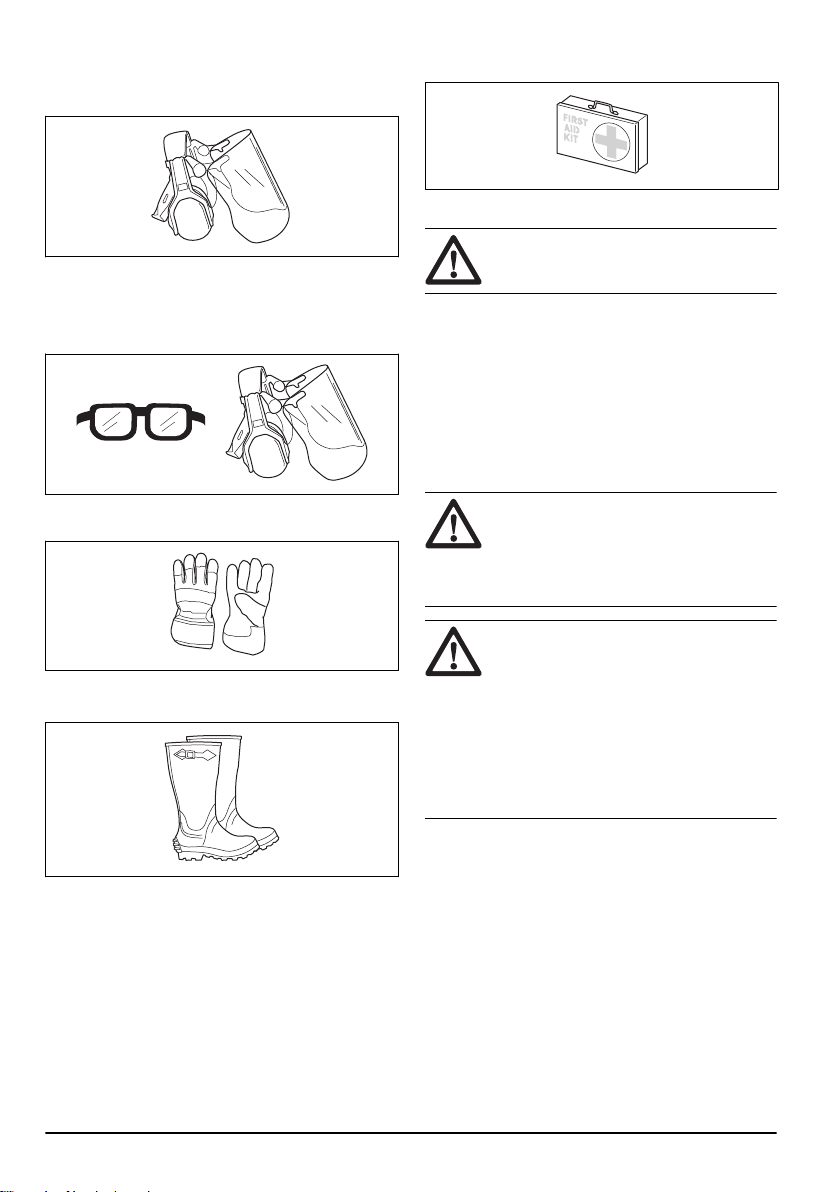
• Use approved hearing protection that provides
adequate noise reduction. Long-term exposure to
noise can result in permanent hearing impairment.
• Use approved eye protection. If you use a visor, you
must also use approved protective goggles.
Approved protective goggles must comply with the
ANSI Z87.1 standard in the USAs or EN 166 in EU
countries.
• Use gloves when necessary, for example when you
attach, examine or clean the cutting equipment.
• Use protective boots with steel toes and non-slip
soles.
• Use clothing made of a strong fabric. Always use
heavy, long pants and long sleeves. Do not use
loose clothing that can catch on twigs and branches.
Do not wear jewelry, short pants, sandals or go with
bare feet. Put your hair up safely above shoulder
level.
• Keep first aid equipment close at hand.
Safety devices on the product
WARNING: Read the warning instructions
that follow before you use the product.
In this section the product’s safety features, its purpose
and how checks and maintenance should be carried out
to ensure that it operates correctly. See instructions
under the heading
Product overview on page 2
to find
where these parts are located on your product.
The life span of the product can be reduced and the risk
of accidents can increase if product maintenance is not
carried out correctly and if service and/or repairs are not
carried out professionally. If you need further information
please contact your nearest servicing dealer.
WARNING: Never use a product with
defective safety components. The product's
safety equipment must be inspected and
maintained as described in this section. If
your product fails any of these checks,
contact your service agent to get it repaired.
CAUTION: All servicing and repair work on
the machine requires special training. This is
especially true of the machine′s safety
equipment. If your machine fails any of the
checks described below you must contact
your service agent. When you buy any of
our products we guarantee the availability of
professional repairs and service. If the
retailer who sells your machine is not a
servicing dealer, ask him for the address of
your nearest service agent.
To do a check of the throttle trigger lockout
The throttle lockout is designed to prevent accidental
operation of the throttle control.
6
1363 - 001 - 25.10.2019
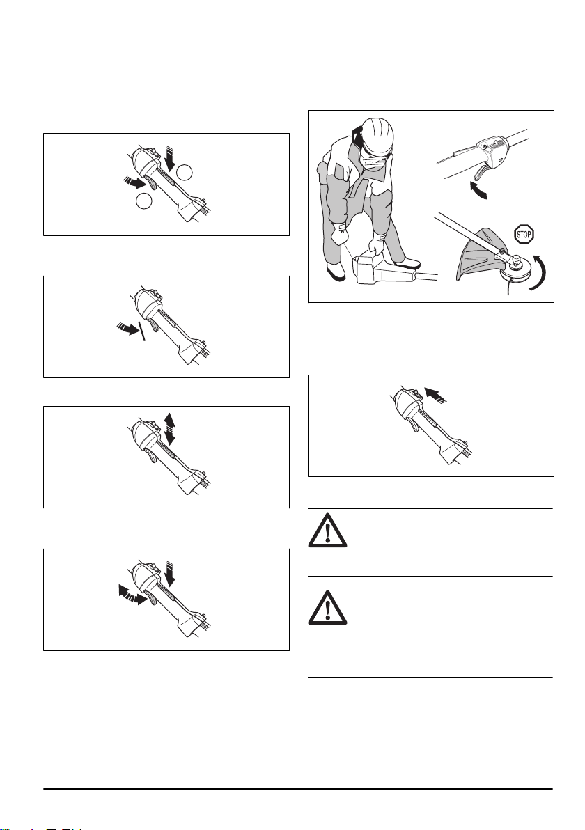
1. Press the throttle trigger lockout (A) and make sure
that the throttle control is released (B). When you
release the handle the throttle control and the throttle
trigger lockout both move back to their initial
positions. This movement is controlled by two
independent return springs. This arrangement
means that the throttle control is automatically
locked at the idle setting.
A
B
2. Make sure that the throttle control is locked at the
idle setting when the throttle trigger lockout is
released.
3. Press the throttle trigger lockout and make sure that
it returns to its intial position when you release it.
4. Do a check of the throttle control and throttle trigger
lockout move freely and that the return springs work
properly.
5. Start the product (refer to the instructions under
To
start the product on page 17
) and apply full throttle.
6. Release the throttle and make sure that the cutting
attachment stops and remains at a standstill. If the
cutting attachment rotates with the throttle in the idle
position the carburettor idle setting must be checked.
See instructions under the chapter
To adjust the idle
speed on page 21
.
To do a check of the stop switch
1. Start the engine.
2. Move the stop switch to the stop position and make
sure that the engine stops.
To do a check of the cutting attachment guard
WARNING:
Do not use a cutting attachment
without an approved and correctly attached
cutting attachment guard. See
To attach the
grass blade and the grass blade guard/
combination guard on page 13
.
WARNING: Always use the recommended
cutting attachment guard for the cutting
attachment that you use. If an incorrect or
faulty cutting attachment guard is fitted this
can cause serious personal injury. See
intructions under heading
Accessories on
page 26
.
The cutting attachment guard prevents injuries from
objects that eject in the direction of the operator. It also
1363 - 001 - 25.10.2019
7
prevents injuries that occur if you touch the cutting
attachment.
1. Make sure that the cutting attachment guard is not
damaged or cracked.
2. Replace the guard if it has been exposed to impact
or is cracked.
To do a check of the vibration damping system
WARNING: Use of incorrectly wound cord or
an incorrect cutting attachment increases
the level of vibration.
The vibration damping system decreases vibration in the
handles to a minimum which makes the operation
easier. The vibration damping system decreases the
vibrations between the engine unit and the shaft unit.
1. Stop the engine.
2. Do a visual check for deformation and damage, for
example cracks.
3. Make sure that the vibration damping units are
attached correctly.
To do a check of the muffler
The muffler keeps noise levels to a minimum and sends
exhaust fumes away from the operator.
• Do a visual check for damage and deformation.
• Make sure that the muffler is correctly attached to
the product.
• If the muffler on your product has a spark arrester
screen, do a visual check. Replace the spark
arrester screen if it is damaged.
a) Clean the spark arrester screen if it is blocked. A
blocked spark arrester screen causes the engine
to become too hot which causes damage to the
engine.
b) Make sure that the spark arrestor mesh is
attached correctly.
8
1363 - 001 - 25.10.2019
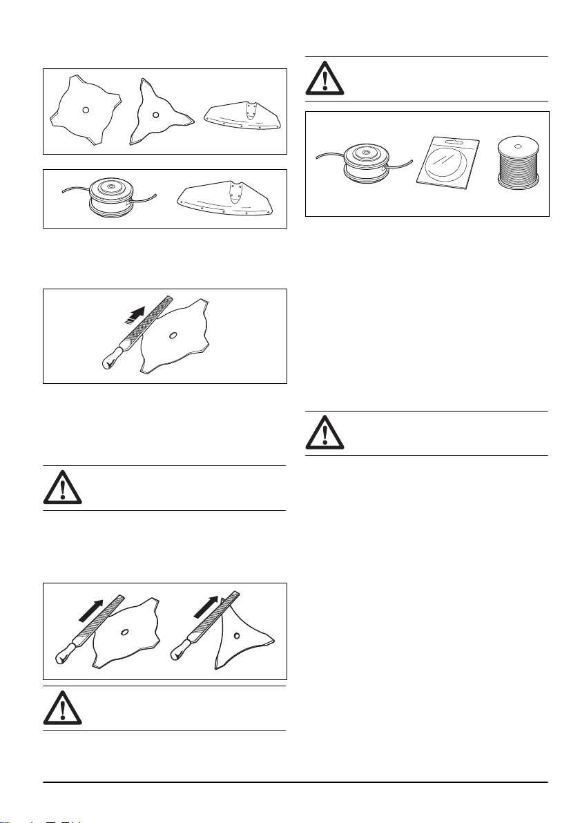
Cutting equipment
• Use the blades and grass knives to cut coarse grass.
• Use the trimmer head to cut grass.
• An incorrectly sharpened or damaged blade
increases the risk of accidents. Keep the teeth of the
blade correctly sharpened. Follow the instructions in
Maintenance on page 19
and use the
recommended file gauge.
• Examine the cutting attachment for damage and
cracks. Replace the damaged cutting attachment.
• Only use cutting attachments with recommended
guards. See
Accessories on page 26
.
To sharpen the grass knife and grass blade
WARNING: Stop the engine. Use protective
gloves.
• To sharpen the grass knife or grass blade correctly,
refer to the instructions that come with the cutting
attachment.
• Sharpen all edges equally to keep the balance.
• Use a single-cut flat file.
WARNING:
Always discard a blade that is
damaged. Do not try to make a bent or
twisted blade straight and use it again.
Trimmer head
WARNING: Always make sure the trimmer
line is wound tightly and evenly around the
drum to prevent harmful vibration.
• Only use recommended trimmer heads and trimmer
lines.
• Only use recommended cutting attachments.
• Smaller machines requires small trimmer heads and
vice versa.
• The length of the trimmer line is important. A longer
trimmer line requires greater engine power than a
shorter trimmer line of the same diameter.
• Make sure that the cutter on the trimmer guard is
intact. This cuts the trimmer line to the correct
length.
• Soak the trimmer line in water for a couple of days
before use to increase the life length.
Fuel Safety
WARNING: Read the warning instructions
that follow before you use the product.
• Never start the product if you spill fuel on it. Wipe the
spillage of and allow remaining fuel to evaporate.
• Never start the product if you spill fuel on yourself or
your clothes. Change your clothes and wash any
part of your body that has come in contact with fuel.
Use soap and water.
• Never start the product if the product is leaking fuel.
Check regularly for leaks from the fuel cap and fuel
lines.
• Always put the product on a flat surface and make
sure the cutting attachment cannot come in contact
with any object while you add fuel.
• Take care when handling fuel. Bear in mind the risk
off fire, explosion and inhaling fumes.
• Observe caution when handling fuel and make sure
there is adequate ventilation. Fuel and fuel fumes
are highly inflammable and can cause serious injury
when inhaled or allowed to come in contact with the
skin.
• Mix and pour fuel outdoors, where there are no
sparks or flames.
• Do not smoke or place hot objects near fuel.
• Always stop the engine and let it cool off for a few
minutes before you refuel.
1363 - 001 - 25.10.2019
9
• Open the fuel cap slowly so that any excess
pressure is released gently when you refuel.
• Tighten the fuel cap carefully after you refueled.
• Clean the area around the fuel cap. Contamination in
the tank can cause operating problems.
• Always move the product 3m (10ft) or further from
the refuelling area and source before starting.
Safety instructions for maintenance
WARNING: Always stop the engine before
you do any work on the cutting attachment.
The cutting attachment continues to rotate
even after the throttle has been released.
Ensure that the cutting attachment has
stopped completely and disconnect the
spark plug before you start to work on it.
WARNING: A faulty cutting attachment may
increase the risk of accidents.
WARNING: Make sure that the trimmer cord
is wound tightly and evenly around the
drum, otherwise the product will generate
harmful vibration.
• Only use cutting attachments with the guards we
recommend. Refer to
Accessories on page 26
.
Assembly
Introduction
WARNING: Before you assemble the
product, you must read and understand the
safety chapter.
WARNING: Remove the spark plug cable
from the spark plug before you assemble the
product.
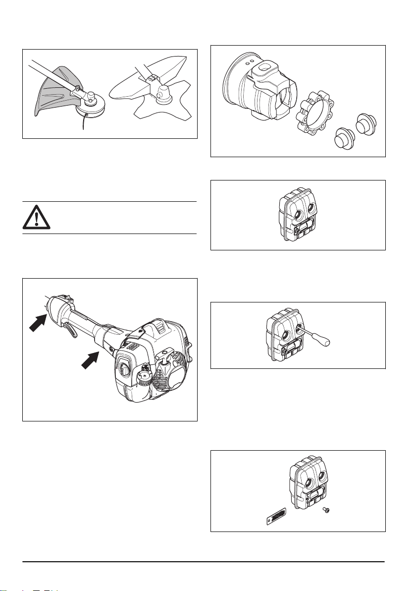
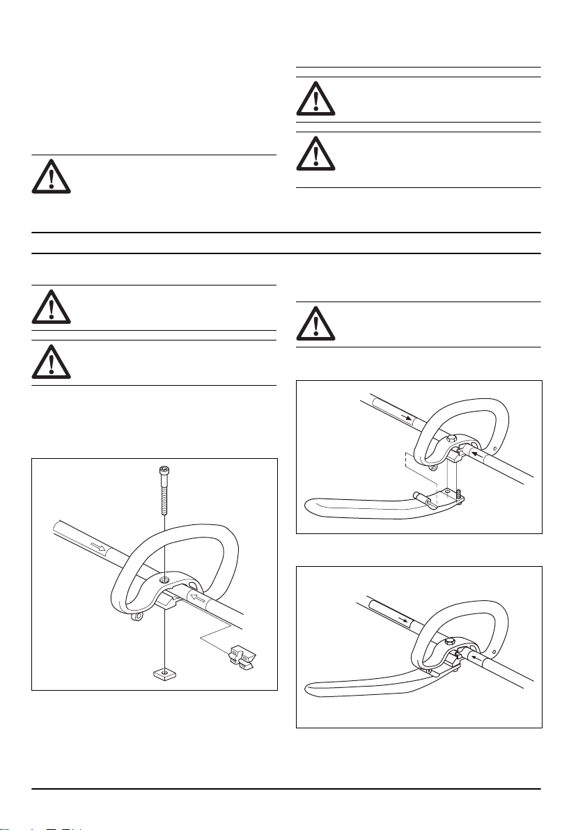
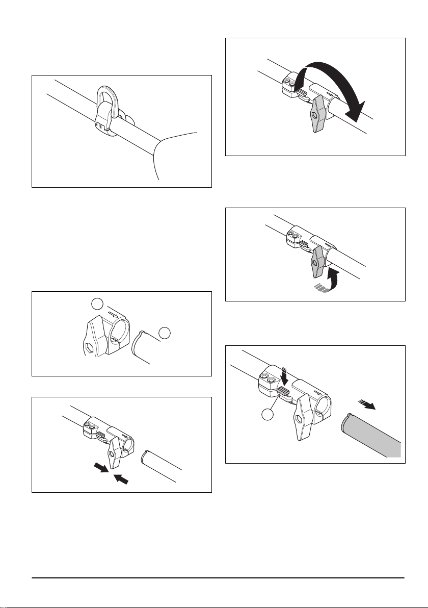
To assemble the loop handle (525LST,
525RJD)
1. Attach the loop handle onto the shaft between the
arrows.
2. Install the spacer into the slot of the loop handle.
3. Attach the nut, the knob and the screw. Do not make
it too tight.
4. Adjust the product to a correct work position.
5. Tighten the bolt.
To assemble the J-handle (525LST,
525RJD)
WARNING: Do not use saw blades with the
J-handle.
1. Attach the J-handle to the loop handle with 3 screws.
Do not tighten the screws fully.
2. Adjust the product to a comfortable position.
3. Tighten the screws.
10 1363 - 001 - 25.10.2019
To install the suspension ring (525LST,
525RJD)
1. Install the suspension ring to the shaft between the
rear handle and the loop handle.
2. Adjust the ring to make the product balanced and
easy to use.
3. Attach the harness to the suspension ring. Use the
harness when you operate the product.
To assemble the two-piece shaft
(525RJD)
1. Turn the knob to loosen the coupling.
2. Align the tab of the cutting attachment (A) with the
arrow of the coupling (B).
A
B
3. Carefully push the shaft into the coupling until you
hear a click.
4. Tighten the knob fully.
To disassemble the two-piece shaft
(525RJD)
1. Turn the knob 3 turns or more to loosen the
coupling.
2. Push and hold the button (C).
3. Hold tight in the end of the shaft that the engine is
attached to.
4. Pull the attachment straight out of the coupling.
C
To assemble the cutting attachment
guard and trimmer head
1. Attach the correct cutting attachment guard (A) for
the trimmer head. Refer to
Accessories on page 26
.
2. Put the cutting attachment guard onto the fitting on
the shaft.
1363 - 001 - 25.10.2019
11
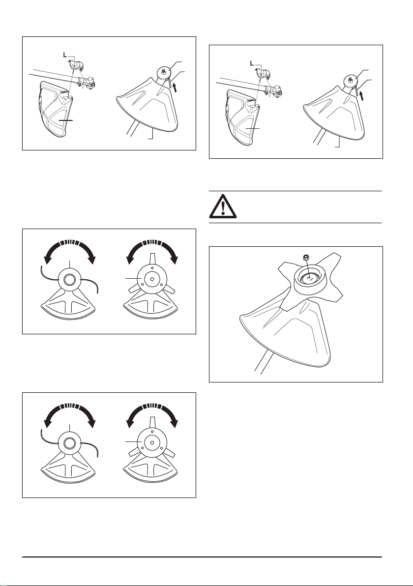
3. Attach with the bolt (L).
A
A
B
C
4. Install the drive disc (B) on the output shaft.
5. Turn the output shaft until one of the holes in the
drive disc aligns with the related hole in the gear
housing.
6. Put the locking pin (C) in the hole to lock the shaft.
7. Turn the trimmer head /plastic blades (H) in the
opposite direction from which the trimmer head/
plastic blades rotates.
H
H
To disassemble the cutting attachment
guard and trimmer head
1. Turn the trimmer head /plastic blades (H) in the
direction from which the trimmer head/plastic blades
rotates.
H
H
2. Pull the locking pin (C) out from the hole to unlock
the shaft.
3. Remove the drive disc (B) on the output shaft.
4. Loosen the bolt(L) from the cutting attachment
guard-fitting on the shaft.
A
A
B
C
5. Remove the cutting attachment guard (A).
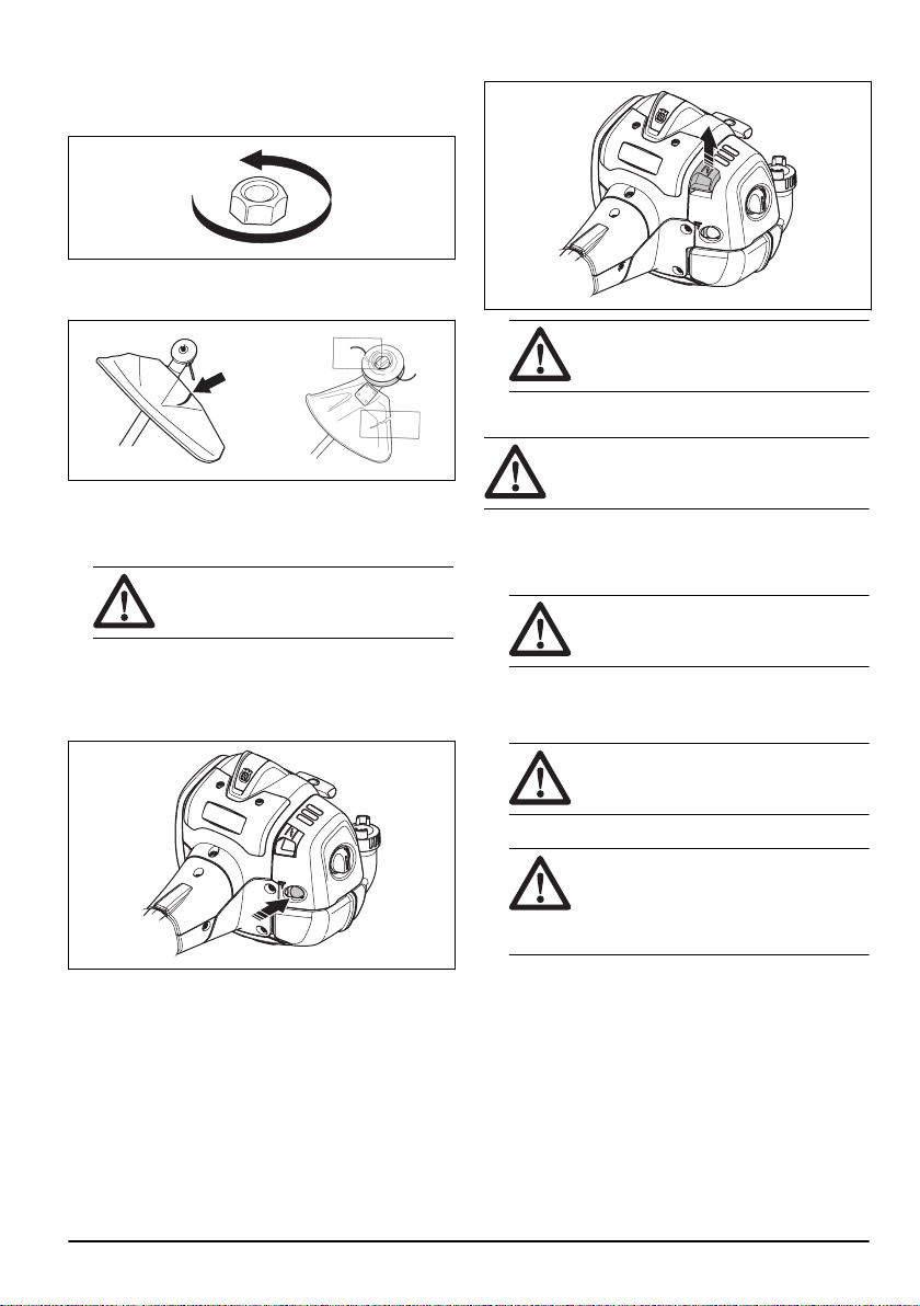
To attach and remove the locknut
WARNING: Stop the engine, use protective
gloves and be careful around the sharp
edges of the cutting attachment.
A locknut is used to attach some types of cutting
attachments. The locknut has a left thread.
• To attach, tighten the lock nut in the opposite
direction to the direction of rotation of the cutting
attachment.
• To remove the locking nut, undo the lock nut in the
same direction as the cutting attachment rotates.
12
1363 - 001 - 25.10.2019
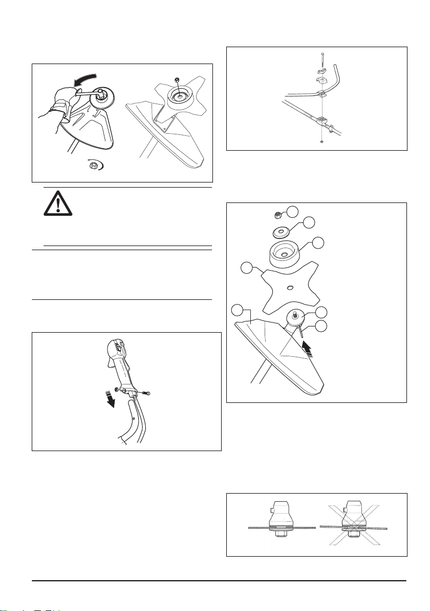
• To loose and tighten the locknut, use a socket
spanner with a long shaft. The arrow in the picture
shows the area where you should operate the socket
spanner.
WARNING: When you loose and tighten
the locknut there is a risk of injury from
the teeth of the saw blade. You should
therefore always ensure that your hand
is shielded by the blade guard when you
do this.
Note: Make sure that you can not turn the locknut by
hand. Replace the nut if the nylon lining does not have a
resistance of a minimum of 1.5 Nm. The nut should be
replaced after it has been put on approximately 10
times.
To assemble the handlebar (525RS)
1. Remove the screw on the throttle handle.
2. Align the hole on the throttle handle with the hole in
the handlebar.
3. Put the screw through the holes. Tighten the screw.
4. Attach the handlebar between the arrows on the
shaft. Tighten the screw.
To attach the grass blade and the
grass blade guard/combination guard
1. Put the blade guard/combination guard (A) onto the
shaft and tighten the bolt to attach it.
G
F
D
B
C
A
E
2. Turn the output shaft to align 1 of the holes in the
drive disc (B) with the related hole in the gear
housing.
3. Put the locking pin (C) in the hole to lock the shaft.
4. Put the grass blade (D), the support cup (E) and the
support flange (F) on the output shaft.
5. Make sure that the drive disc and support flange
engages correctly in the center hole of the grass
blade.
1363 - 001 - 25.10.2019
13
6. Attach the nut (G).
7. Tighten the nut to the support flange with the socket
wrench. Hold the shaft of the socket wrench near the
blade guard. Tighten in the opposite direction to how
the cutting attachment rotates. Tighten it to a torque
of 35-50 Nm.
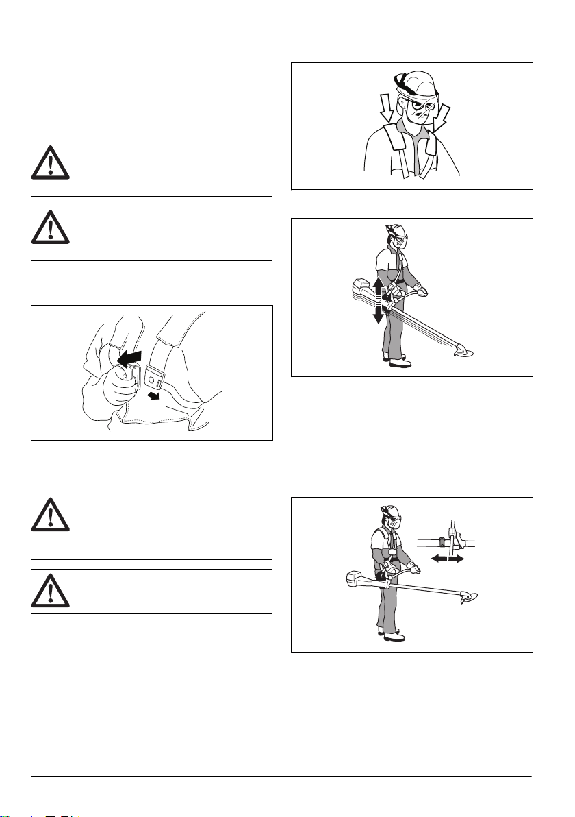
Quick release function of the harness
WARNING: Do not use the harness if the
quick release function is defective. Make
sure that the quick release function operates
correctly when you adjust the product.
WARNING: If the product is not safely
attached to the harness, you can not control
the product and that can result in injury to
you or others.
The quick release function is at the front of the harness.
The harness straps must always stay at the correct
position.
In an emergency, the quick release function helps you to
remove the product safely.
To adjust the harness
WARNING:
Always attach this product to the
harness correctly. If not, you cannot control
the product safely and this can result in
injury to you or others. Do not use a harness
with a defective quick release.
WARNING: Use the harness quick release
function if you must release from the product
and the harness in an emergency situation.
1. Put on the harness.
2. Adjust the harness for the best work position.
3. Adjust the side straps until the weight is equally
applied across your shoulders.
4. Adjust the harness until the cutting attachment is
parallel to the ground.
5. If the operation is to cut grass, let the cutting
attachment stay lightly on the ground. Adjust the
harness clamp to balance the product correctly.
Correct balance of the product
For forestry clearing, the product is correctly balanced
when it freely hangs horizontally from the suspension
point. With correct balance, the risk of hitting stones if
you release the handlebar is decreased.
14
1363 - 001 - 25.10.2019
For grass clearing, the product is correctly balanced
when the blade is at cutting height near the ground.
Operation
Fuel
This product has a two-stroke engine.
CAUTION: Incorrect type of fuel can result in
engine damage. Use a mixture of gasoline
and two-stroke oil.
Gasoline
CAUTION: Always use a quality gasoline/oil
mixture of at least 90 octane (RON). There
is a risk that use of lower octane grade
causes knocking. This gives rise to high
engine temperature, which can result in
serious engine damage.
CAUTION: If your product is equipped with a
catalytic converter use a good quality
unleaded gasoline/oil mixture. Leaded
gasoline will destroy the catalytic converter.
• Use low-emission gasoline, also know as alkylate
gasoline, if it is available.
• Ethanol blended fuel, E10 may be used (max 10%
ethanol blend). Using ethanol blends higher than
E10 will cause lean running condition which can
damage the engine.
• We recommend a higher octane rating when you do
work at continuous high speed.
Husqvarna alkylate fuel
We recommend you to use Husqvarna alkylate fuel for
best performance. The fuel contains less dangerous
material compared to regular fuel, which decreases
dangerous exhaust fumes. The fuel gives a low quantity
of dangerous remainings when it is combusted, which
keeps the components of the engine more clean. This
extends the life of the engine. Husqvarna alkylate fuel is
not available in all markets.
Two-stroke oil
CAUTION: Unsatisfactory oil quality and/or
incorrect oil/fuel ratio can damage the
product and decrease the life time of
catalytic converters.
CAUTION: Do not use two-stroke oil for
water-cooled outboard engines, also
referred to as outboard oil.
CAUTION: Do not use oil for four-stroke
engines.
• For best results and performance use Husqvarna
two-stroke oil.
• If Husqvarna two-stroke oil is not available, use a
different two-stroke oil of good quality for air-cooled
engines. Speak to your servicing dealer to select the
correct oil.
Gasoline, l
Two-stroke oil, l
2% (50:1)
5 0.10
10 0.20
1363 - 001 - 25.10.2019 15
15 0.30
20 0.40
To mix gasoline and two-stroke oil
CAUTION: There is a risk that small errors
influence the ratio of the mixture drastically
when you mix small quantities of fuel.
Carefully measure the quantity of oil to be
mixed to make sure that you get the correct
mixture.
1. Fill half the quantity of the gasoline to be used.
2. Add the full quantity of oil and mix (shake) the fuel
mixture.
3. Add the remaining quantity of gasoline.
4. Carefully mix (shake) the fuel mixture and fill the fuel
tank of the product.
5. Empty and clean the fuel tank if you do not use the
product for some time.
Note:
Do not mix fuel for more than 1 month at a time
and always mix gasoline and oil in a clean container
intended for fuel.
To fill the fuel tank
1. Clean the area around the fuel tank cap.
2. Shake the container and make sure that the fuel is
fully mixed. Use a fuel container with an anti-spill
valve.
3. Fill the fuel tank.
4. Tighten the fuel tank cap carefully.
5. Move the product 3 m (10 ft) or more away from the
refueling area and fuel source before starting.
CAUTION:
Contamination in the tanks
causes malfunction. Clean the fuel tank and
chain oil tank regularly and replace the fuel
filter one time a year or more.
To do before you operate the product
• Examine the work area to make sure that you know
the type of terrain and the slope of the ground. Look
after if there are obstacles such as stones, branches
and ditches.
• Do an inspection of the product.
• Do maintenance and servicing that are given in this
manual.
• Make sure that all covers, guards, handles and the
cutting equipment are correctly attached and not
damaged.
• Make sure that there are no cracks on the saw blade
or the grass blade . Replace the blade if it is
damaged.
• Examine the support flange for cracks. Replace the
support flange if it is damaged.
16
1363 - 001 - 25.10.2019
• Make sure that the locknut can not be removed by
hand. If you can remove it by hand, it does not lock
the cutting attachment sufficiently and you must
replace it.
• Examine the blade guard for damages or cracks.
Replace the blade guard if it has been hit or if it has
cracks.
• Examine the trimmer head and cutting attachment
guard for damages or cracks. Replace the trimmer
head and cutting attachment guard if they have been
hit or if they have cracks.
WARNING: Do not use the product
without a guard or a guard that is
defective.
To prepare a cold engine for start
1. Push the air purge bulb again and again until fuel
starts to fill the bulb. It is not necessary to fill the air
purge bulb fully.
2. Move the choke control up into choke position.
WARNING: The cutting attachment
starts to rotate immediately when you
start the engine with the choke.
To start the product
WARNING: Read the warning instructions in
the safety chapter before you start the
product (refer to
Safety on page 4
).
1. Use protective gloves.
2. Hold the body of the product on the ground with your
left hand.
CAUTION: Do not use your feet!
3. Hold the starter rope handle.
4. Slowly pull out the starter rope with your right hand
until you feel some resistance (the starter pawl grip).
WARNING:
Do not twist the starter rope
around your hand.
5. Pull the cord quickly and with power.
CAUTION:
Do not pull the starter rope all
the way out and do not let go off the
starter rope handle when the starter rope
is fully extended. This can cause
damage to the product.
6. Pull the starter rope again and again until the engine
starts.
7. Reset the choke when the engine fires.
8. Operate the throttle gradually when the engine
starts.
9. Make sure the engine runs smoothly.
1363 - 001 - 25.10.2019
17
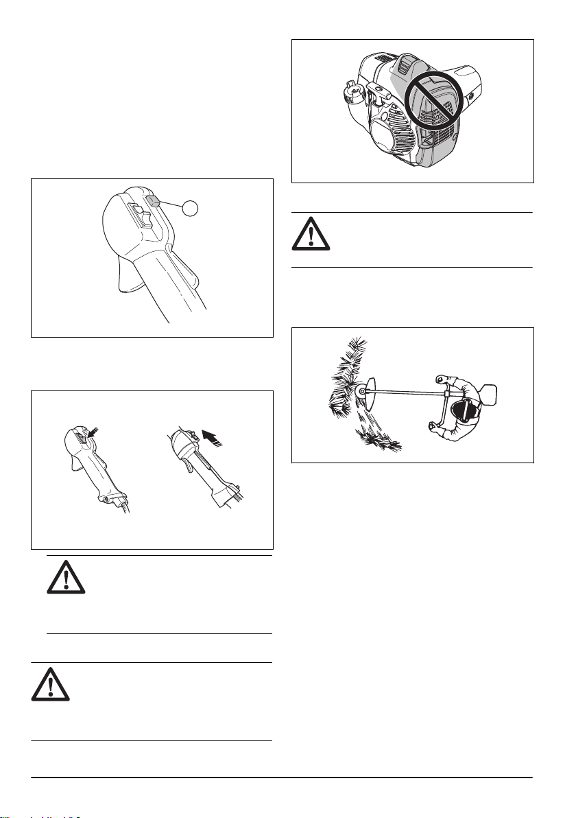
To start with a throttle handle with a
start throttle lock (525RS)
1. Push the throttle lockout and the throttle trigger to
set the throttle to the start position. Then push the
start throttle button (A).
2. Release the throttle lockout and the throttle trigger,
followed by the start throttle button. The throttle
function is now activated.
3. To return the engine to idle speed, push the throttle
lockout and throttle trigger again.
A
To stop the product
• Move the stop switch to the stop position to stop the
engine.
525RS
525LST, 525RJD
CAUTION: The stop switch automatically
goes back to start position. To prevent
accidental start, remove the spark plug
cap from the spark plug when you
assemble or do maintenance on the
product.
About the surface
WARNING:
Do not touch the area that is
identified with gray in the illustration. There
is a risk of burn injuries when the product is
hot. There is a risk of electrical shock if the
spark plug cap is damaged. Do not use a
product that has a damaged spark plug cap.
Grass clearing with a grass blade
CAUTION: Do not use grass blades and
grass knives on wood. Use grass blades
and grass knives for long or heavy grass
only.
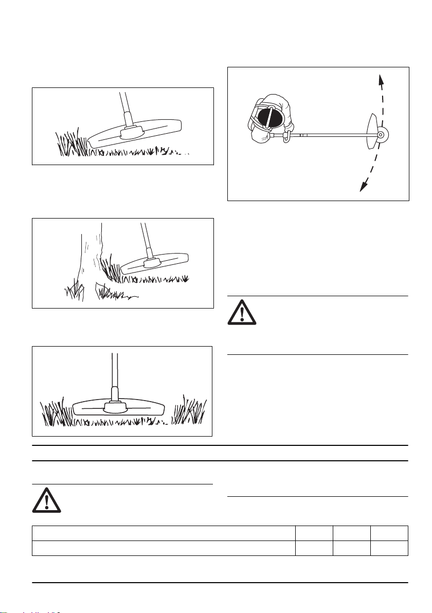
• Move the product from side to side.
• Start the movement from right to left when you cut.
Move the product to the right before you cut again.
• Cut with the left side of the grass blade.
• Angle the grass blade to the left to make the grass
fall in a line. This makes it easy to collect the grass.
• Keep a stable position with your feet apart.
• Move forward after each right movement and make
sure that you have a stable position again before you
cut again.
• Keep the support cup with a light pressure against
the ground to make sure that the grass blade does
not hit the ground.
• Obey these instructions to decrease the risk that cut
material winds around the grass blade:
a) Apply full throttle.
b) Do not move the grass blade through cut
material when you move the product from left to
right.
• Before you collect the cut material, stop the engine
and remove the product from the harness. Put the
product down on the ground.
18
1363 - 001 - 25.10.2019
Grass trimming with a trimmer head
To trim the grass
1. Hold the trimmer head immediately above the
ground at an angle. Do not push the trimmer line into
the grass.
2. Decrease the length of the trimmer line by 10-12
cm / 4-4.75 in.
3. Decrease the engine speed to decrease the risk of
damage to plants.
4. Use 80 % throttle when you cut grass near objects.
To cut the grass
1. Make sure that the trimmer line is parallel to the
ground when you cut the grass.
2. Do not push the trimmer head to the ground. This
can cause damage to the product.
3. Move the product from side to side when you cut
grass. Use full speed.
To sweep the grass
The airflow from the rotating trimmer line can be used to
remove cut grass from an area.
1. Hold the trimmer head and the trimmer line parallel
to the ground and above the ground.
2. Apply full throttle.
3. Move the trimmer head from side to side and sweep
the grass.
WARNING: Clean the trimmer head cover
each time you assemble new trimmer line to
prevent unbalance and vibrations in the
handles. Also do a check of the other parts
of the trimmer head and clean it if
necessary.
Maintenance
Maintenance schedule
WARNING: Only do the maintenance and
servicing given in this operator's manual. For
maintenance or servicing that is not given in
this operator's manual, speak to your
servicing dealer.
Maintenance Daily Weekly Monthly
Clean the external surface. X
1363 - 001 - 25.10.2019 19

Maintenance Daily Weekly Monthly
Make sure that the throttle trigger lockout and the throttle trigger operates cor-
rectly.
X
Do a check of the stop switch to make sure that it operates correctly. X
Make sure that the cutting attachment does not rotate at idle speed. X
Clean the air filter. Replace the air filter if it is necessary. X
Examine the cutting attachment guard for damages and cracks. Replace the
guard if it is hit or damaged.
X
Examine the trimmer head for damages and cracks. Replace the trimmer head if
it is damaged.
X
Make sure that the screws and nuts are tight. X
Examine the engine, the fuel tank and the fuel lines for leaks. X
Clean the cooling system. X
Examine the starter and the starter rope for damages. X
Examine the vibration damping elements for damages and cracks. X
Clean the external parts of the spark plug. Remove it and do a check of the elec-
trode gap. Adjust the electrode gap to the correct distance, refer to
Technical da-
ta on page 25
or replace the spark plug. Make sure that the spark plug is fitted
with a suppressor.
X
Clean the external parts of the carburetor and the area around it. X
Do a check of the bevel gear to make sure that it is filled ¾ with grease. Fill the
bevel gear with Husqvarna special grease if it is necessary.
X
Clean or replace the spark arrestor mesh on the muffler (only applies to mufflers
without a catalytic converter).
X X
Do a check of the fuel filter for contamination and the fuel hose for cracks or oth-
er defects. Replace parts if it is necessary.
X
Do a check of all the cables and connections. X
If it is necessary to replace the clutch, clutch springs or clutch drum, speak to
your servicing dealer.
X
Replace the spark plug. Make sure that the spark plug is fitted with a suppres-
sor.
X
Carburetor function
The carburetor supplies a mixture of fuel and air to the
engine. The quantity of this mixture is controlled by the
throttle. The proportions of fuel and air in the mixture is
controlled by the adjustable high and low speed jets.
The jets must be correctly adjusted for the engine to
have maximum power at different speeds. A correctly
adjusted carburetor gives the engine maximum power at
different speeds. It also gives the engine a smooth idle
speed and makes it possible to increase engine speed
quickly.
The correct adjustment of the carburetor can change if
the air moisture, temperature and air pressure changes.
The carburetor has 3 adjustment controls.
• L = low speed jet
• H = high speed jet
• T = idle speed
20 1363 - 001 - 25.10.2019
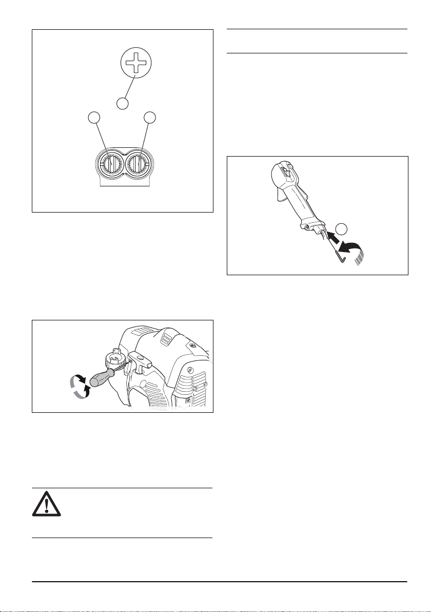
H
L
T
Turn the H-jet and L-jet clockwise to get less fuel in the
mixture and counterclockwise to get more fuel in the
mixture. Less fuel in the mixture gives a higher engine
speed and more fuel in the mixture gives lower speed.
To adjust the idle speed
1. Make sure that the air filter is clean and the air filter
cover is installed.
2. Adjust the idle speed with the idle adjustment screw.
The idle adjustment screw T is identified with a "T"
mark.
3. Turn the idle adjustment screw clockwise until the
cutting attachment starts to turn.
4. Turn the idle adjustment screw counterclockwise
until the cutting attachment stops.
The idle speed is correct when the engine operates
smoothly in all positions. The idle speed must be below
the speed when the cutting attachment starts to turn.
WARNING:
If the cutting attachment does
not stop when you adjust the idle speed,
turn to your nearest servicing dealer. Do not
use the product until it is correctly adjusted
or repaired.
Note: Refer to
Technical data on page 25
for the
recommended idle speed.
To adjust the start throttle speed
(525RS)
1. Apply idle speed.
2. Push the start throttle lock. Refer to
Product
overview on page 2
.
3. If the start throttle speed is less than 4000 rpm, turn
the adjuster screw (A) clockwise until the cutting
attachment rotates. Turn the adjuster screw (A)
clockwise) 1/2 turn more.
A
4. If the start throttle speed is too high, turn the adjuster
screw (A) counterclockwise until the cutting
attachment stops. Turn the adjuster screw (A)
clockwise 1/2 turn more.
To do maintenance on the trimmer
head
1. Only use the recommended cutting attachment and
cutting attachment guard. Refer to
Accessories on
page 26
.
2. Make sure that the cutter on the cutting attachment
guard is not damaged, it cuts the cord to the correct
length.
3. Install the cord as the illustrations on the last pages
of the manual shows.
Cooling system
The product has a cooling system to keep the operation
temperature as low as possible.
Clean the components of the cooling system with a
brush weekly or more frequently in rougher conditions. A
dirty or blocked cooling system makes the product too
hot which causes damage to the piston and cylinder.
The cooling system has the following components:
1. Air intake on the starter.
2. Fins on the flywheel.
3. Cooling fins on the cylinder.
4. Cylinder cover.
5. Muffler cover.
1363 - 001 - 25.10.2019
21
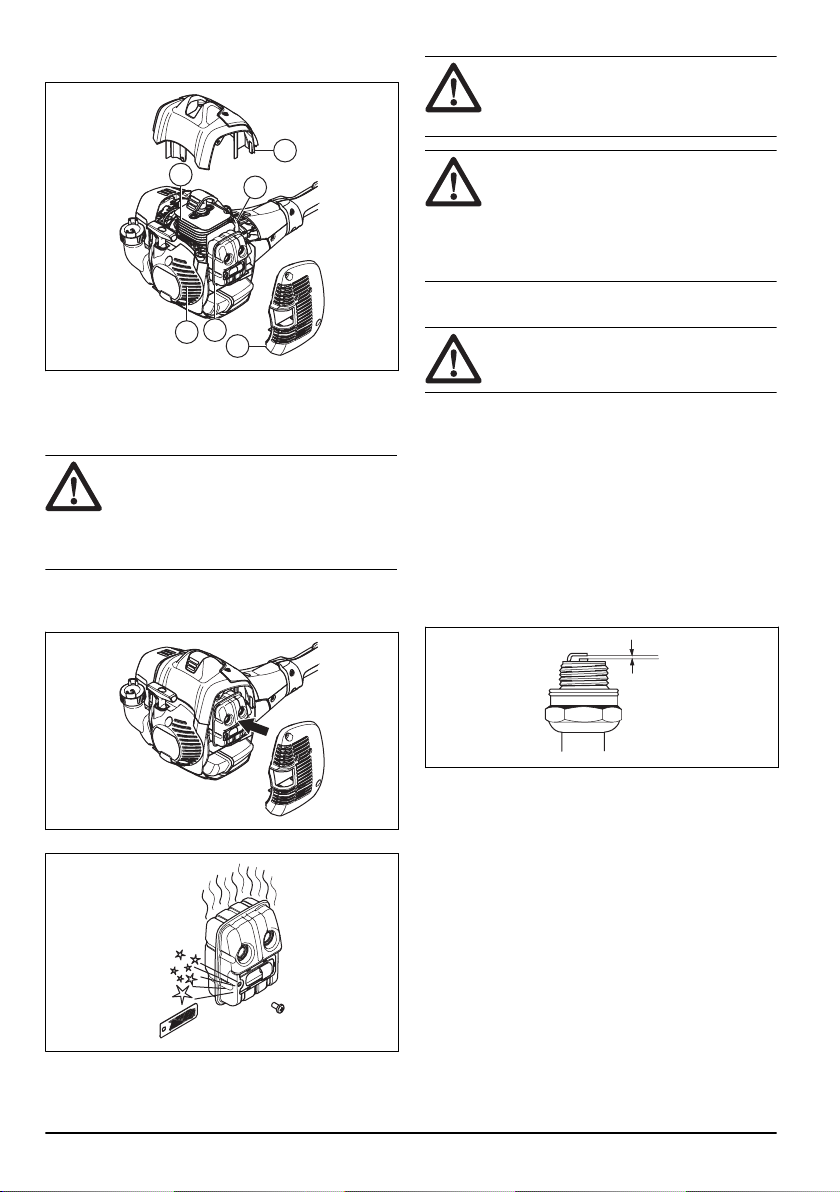
6. Muffler plate.
1
6
3
4
5
2
To do maintenance on the muffler
The muffler decreases the noise level and directs the
exhaust gases away from the operator.
WARNING: Mufflers that have catalytic
converters get very hot during operation and
will stay hot for some time after you stop the
product. This also applies at idle speed. If
you touch the product it can result in burns
to the skin. Think about of the risk of fire.
1. Stop the product and let it cool down.
2. Remove the cover to the muffler.
3. Remove the screw holding the spark arrestor mesh.
4. Clean the spark arrestor mesh if it is blocked or
replace it if it is damaged.
CAUTION:
The spark arrestor mesh must be
replaced if it is damaged. Do not use a
product if the spark arrestor mesh on the
muffler is missing or defective.
CAUTION: If the spark arrestor mesh is
frequently blocked it can be a sign that
performance of the catalytic converter is
decreased. Turn to your servicing dealer to
examine the muffler. A blocked spark
arrestor mesh will cause overheating and
result in damage to the cylinder and piston.
To examine the spark plug
CAUTION: Always use the recommended
spark plug type. Incorrect spark plug type
can cause damage to the product.
• Examine the spark plug if the engine is low on
power, is not easy to start or does not operate
correctly at idle speed.
• To decrease the risk of unwanted material on the
spark plug electrodes, obey these instructions:
a) Make sure that the idle speed is correctly
adjusted.
b) Make sure that the fuel mixture is correct.
c) Make sure that the air filter is clean.
• If the spark plug is dirty, clean it and make sure that
the electrode gap is correct, refer to
Technical data
on page 25
.
• Replace the spark plug if it is necessary.
Air filter
Remove dust and dirt from the air filter to keep it clean in
order to prevent:
• Carburettor malfunctions.
• Starting problems.
• Loss of engine power.
• Unnecessary wear to engine parts.
• Too much fuel consumption.
Clean the air filter at an interval of 25 hours, or more
regularly if conditions are unusually dusty.
22
1363 - 001 - 25.10.2019
To clean the air filter
CAUTION: A air filter that is damaged, very
dirty or soaked with fuel must always be
replaced.
If you use an air filter for a long time it cannot be fully
cleaned. Replace the air filter with a new one at regular
intervals.
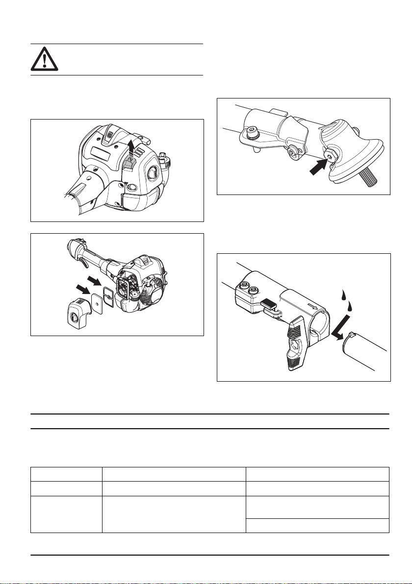
1. Move the choke lever up, to close the choke valve.
2. Remove the air filter cover and remove the air filter.
3. Clean the air filter with warm soap water.
4. Replace the air filter if it is too dirty to fully clean it.
Always replace a damaged air filter.
5. Also clean the inner surface of the filter cover. Use
air or a brush.
6. Do a check of the rubber sealing surface. Replace
the filter on the rubber seal if it is damaged.
7. Make sure that the filter is dry before you assemble
it.
Bevel gear
The bevel gear is filled with the right quantity of grease
at the factory. But, before you use the product, make
sure that the bevel gear is 3/4 full with grease. Use
Husqvarna special grease.
The grease in the bevel gear does not need to be
changed unless repairs are carried out.
Two piece-shaft (525RJD)
• Apply grease to the end of the drive shaft after each
30 hours of operation.
Troubleshooting
The engine does not start
Check Possible cause Procedure
Stop switch. The stop switch is in the stop position. Set the stop switch to the start position.
Starter pawls. The starter pawls cannot move freely. Remove the starter cover and clean around
the starter pawls.
Let an approved service agent help you.
1363 - 001 - 25.10.2019 23

Check Possible cause Procedure
Fuel tank. Incorrect fuel type. Drain the fuel tank and fill with correct fuel.
Spark plug. The spark plug is dirty or wet. Make sure that the spark plug is dry and
clean.
The spark plug electrode gap is incorrect. Clean the spark plug. Make sure that the
electrode gap is correct. Make sure that the
spark plug has a supressor.
Refer to technical data for correct electrode
gap.
The spark plug is loose. Tighten the spark plug.
The engine starts but stops again
Check
Possible cause Procedure
Fuel tank. Incorrect fuel type. Empty the fuel tank and fill it with cor-
rect fuel.
Air filter. The air filter is clogged. Clean the air filter.
Transportation, storage and disposal
Transportation and storage
• Store and transport the product and fuel so that
there is no risk that any leakage or fumes comes in
contact with sparks or open flames, for example,
from electrical machinery, electric motors, electrical
relays/switches or boilers.
• When you store and transport fuel always use
approved containers intended for this purpose.
• When you store the product for long periods the fuel
tank must be emptied. Contact your local petrol
station to find out where to dispose excess fuel.
Drain the tank into the appropriate containers and in
a well ventilated area.
• Ensure that the product is cleaned and that a
complete service is carried out before long-term
storage.
• The transport guard must always be fitted to the
cutting attachment when the product is transported
or in storage.
• Secure the product during transport.
• In order to prevent unintentional start of the engine,
the spark plug cap must always be removed during
long-term storage if the product is not under close
supervision and when you perform all service
measures.
• Allow the product to cool before you put in storage.
Disposal
• Obey the local recycling requirements and applicable
regulations.
• Discard all chemicals, such as engine oil or fuel, at a
service center or at an applicable disposal location.
• When the product is no longer in use, send it to a
Husqvarna dealer or discard it at a recycling
location.
24 1363 - 001 - 25.10.2019

Technical data
Technical data
525LST 525RJD 525RS
Engine
Cylinder displacement, cm
3
25.4 25.4 25.4
Idle speed, rpm 3000 3000 3000
Recommended max. speed, rpm 10500 9500 9500
Speed of output shaft, rpm 5500 6500 6500
Max. engine output, according to
ISO 8893, kW @ rpm
1.0 @ 8500 1.0 @ 8500 1.0 @ 8500
Catalytic converter muffler Yes Yes Yes
Ignition system
Spark plug NGK BPMR8Y NGK BPMR8Y NGK BPMR8Y
Electrode gap, mm 0.65 0.65 0.65
Fuel and lubrication system
Manufacturer/type of carburetor Walbro WTEA-8D Walbro WTEA-8D Walbro WTEA-8D
Fuel tank capacity, liter 0.51 0.51 0.51
Weight
Without fuel, cutting attachment
and guard, kg
4.7 4.9 5.0
Noise emissions
1
Sound power level, measured dB
(A)
109 109 109
Sound power level, guaranteed
L
WA
dB (A)
110 110 110
Sound levels
2
Equivalent sound pressure level at
the operator’s ear, measured ac-
cording to EN ISO 11806 and ISO
7917, dB(A)
98 98 98
Vibration levels
3
1
Noise emissions in the environment measured as sound power (L
WA
) in conformity with EC directive
2000/14/EC. Reported sound power level for the machine has been measured with the original cutting attach-
ment that gives the highest level. The difference between guaranteed and measured sound power is that the
guaranteed sound power also includes dispersion in the measurement result and the variations between dif-
ferent machines of the same model according to Directive 2000/14/EC.
2
Reported data for equivalent sound pressure level has a typical statistical dispersion (standard deviation) of 1
dB (A).
3
Reported data for equivalent vibration level has a typical statistical dispersion (standard deviation) of 1 m/s
2
.
1363 - 001 - 25.10.2019 25

525LST 525RJD 525RS
Equivalent vibration levels (a
hv,eq
)
at handles, measured according
to EN ISO 11806 and ISO 22867,
m/s
2
:Equipped with trimmer head
(original), left/right
5.8/3.3 4.5/3.9 3.6/2.4
Accessories
Accessories
The accessories are recommended for use in
combination with the specified power heads and have
been evaluated to applicable ISO- and EN safety
requirement standards by the Swedish Machinery
Testing Institute.
Approved accessories Accessory type Cutting attachment guard, art. no.
Blade shaft thread M10
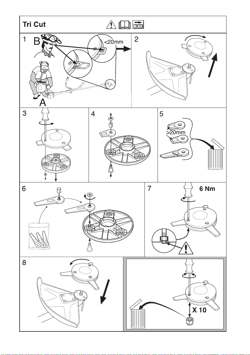
Plastic blades Tricut Ø 300 mm 588 11 79-01
Grass blade/grass cutter Grass 255-4 1" (Ø 255 4-teeth) 588 11 79-01
Trimmer head
Trimmy Fix 588 11 79-01 / 588 54 37-01
Superauto II 588 11 79-01 / 588 54 37-01
S35 588 11 79-01 / 588 54 37-01
T35, T35x 588 11 79-01 / 588 54 37-01
Alloy (up to Ø 2.4 mm cord) 588 11 79-01 / 588 54 37-01
26 1363 - 001 - 25.10.2019
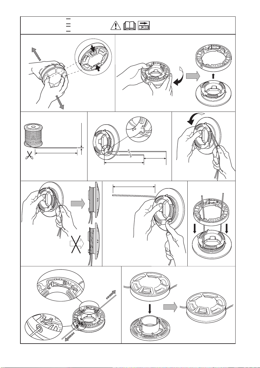
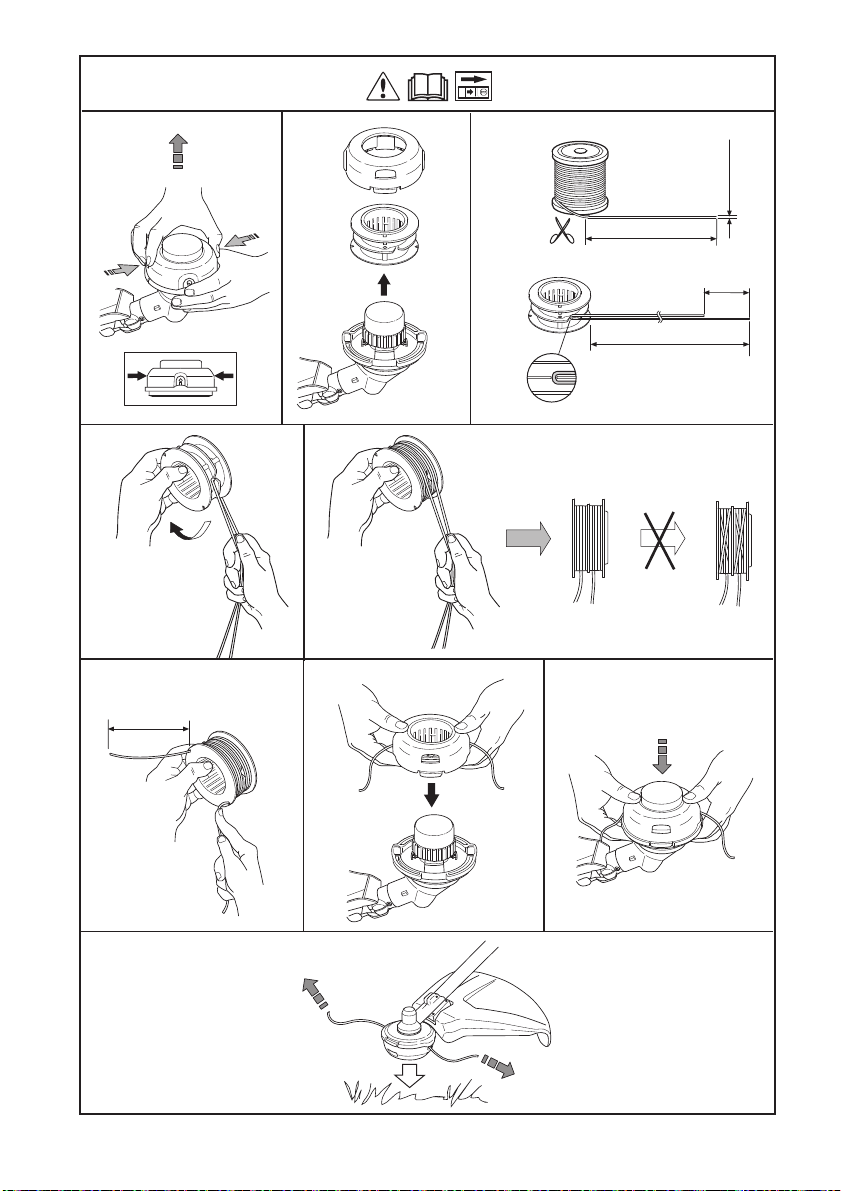
1
Super Auto II
Super Auto II 1
2
3
4
5
6
7
8
9
10
4,0 m
13'
2,4 mm
.095"
~2,0 m
6,5
'
6
"
6
"
"
15 cm
15 cm
"Clic"
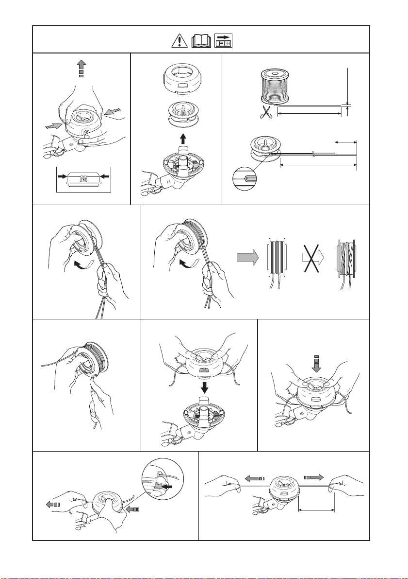
1
2
3
5
6
7
10
11
8,5 m
28'
4
8
4,2 m
14'
2,4-2,7 mm
.095-.106"
10 cm
4"
6"
15 cm
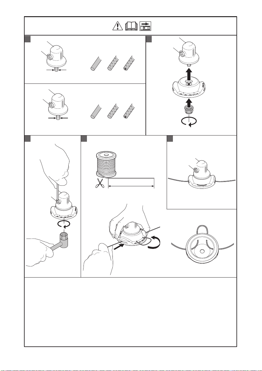
S35
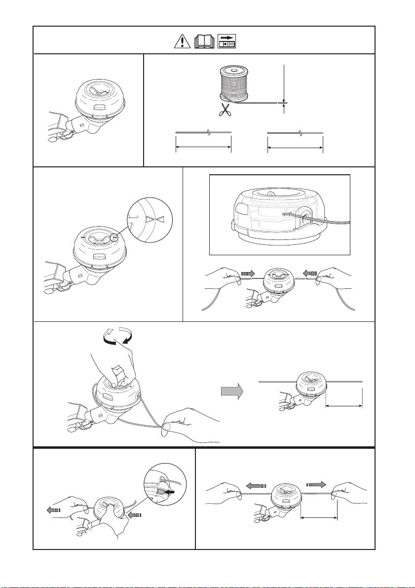
1
2
4
3
2,4-2,7 mm
.095-.106"
4,25 m
14'
4,25 m
14'
B
6"
15 cm
A
6"
15 cm
S35
5
T35, T35x
"Clic"
1
2
3
5
6
7
9
8,5 m
28'
4
8
4,3 m
14'
2,4-2,7 mm
.095-.106"
10 cm
4"
6"
15 cm
1 2
3 4
5
ø 2,0 - 2,4 mm/ .080-.095"
ø 2,0 - 3,3 mm/ .080- .130"
M10
M12
550 mm/ 22"
Alloy


www.husqvarna.com
Original instructions
1159916-28
2019-10-25