OWNER’S MANUAL
MANUALE UTENTE
QPS 10K
QPS 6.0K
FOUR-CHANNEL POWER AMPLIFIERS


3
CONTENTS
CONTENTS .................................................................................................................................................................. 3
ENGLISH
SAFETY PRECAUTIONS AND GENERAL INFORMATION ................................................................................................. 4
DESCRIPTION .............................................................................................................................................................. 8
UNPACKING AND INSTALLATION ................................................................................................................................ 8
FRONT PANEL ............................................................................................................................................................. 9
REAR PANEL .............................................................................................................................................................. 10
OPERATION MODES .................................................................................................................................................. 13
SPEAKON CONNECTORS WIRING .............................................................................................................................. 18
COOLING REQUIREMENTS ......................................................................................................................................... 18
ITALIANO
AVVERTENZE PER LA SICUREZZA ............................................................................................................................... 19
DESCRIZIONE ............................................................................................................................................................ 23
DISIMBALLO ED INSTALLAZIONE ............................................................................................................................... 23
PANNELLO FRONTALE ............................................................................................................................................... 24
PANNELLO POSTERIORE ............................................................................................................................................ 25
MODI DI FUNZIONAMENTO ....................................................................................................................................... 28
CABLAGGIO DEI CONNETTORI SPEAKON ................................................................................................................... 33
VENTILAZIONE .......................................................................................................................................................... 33
DIMENSIONS / DIMENSIONI ....................................................................................................................................... 34
SPECIFICATIONS / SPECIFICHE TECNICHE .................................................................................................................. 35
4
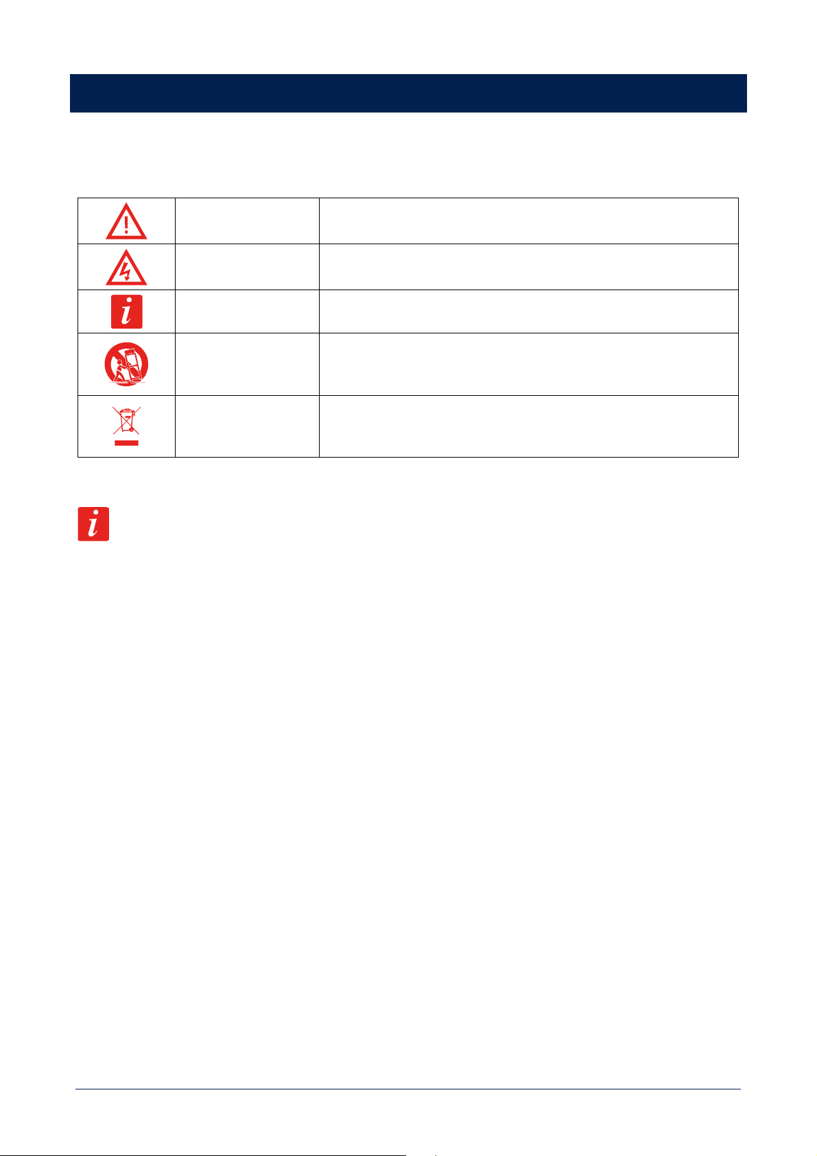
SAFETY PRECAUTIONS AND GENERAL INFORMATION
Symbols used in this document give notice of important operating instructions and warnings which must be strictly
followed.
CAUTION
Important operating instructions: explains hazards that could damage a
product, including data loss
WARNING
Important advice concerning the use of dangerous voltages and the
potential risk of electric shock, personal injury or death.
IMPORTANT NOTES
Helpful and relevant information about the topic
SUPPORTS,
TROLLEYS AND
CARTS
Information about the use of supports, trolleys and carts. Reminds to
move with extreme caution and never tilt.
WASTE DISPOSAL
This symbol indicates that this product should not be disposed with your
household waste, according to the WEEE directive (2012/19/EU) and your
national law.
IMPORTANT NOTES
This manual contains important information about the correct and safe use of the device. Before connecting and using
this product, please read this instruction manual carefully and keep it on hand for future reference. The manual is to be
considered an integral part of this product and must accompany it when it changes ownership as a reference for correct
installation and use as well as for the safety precautions. RCF S.p.A. will not assume any responsibility for the incorrect
installation and / or use of this product.
SAFETY PRECAUTIONS
1. All the precautions, in particular the safety ones, must be read with special attention, as they provide important
information.
2. Power supply from mains
a. The mains voltage is sufficiently high to involve a risk of electrocution; install and connect this product before plugging
it in.
b. Before powering up, make sure that all the connections have been made correctly and the voltage of your mains
corresponds to the voltage shown on the rating plate on the unit, if not, please contact your RCF dealer.
c. The metallic parts of the unit are earthed through the power cable. An apparatus with CLASS I construction shall be
connected to a mains socket outlet with a protective earthing connection.
d. Protect the power cable from damage; make sure it is positioned in a way that it cannot be stepped on or crushed
by objects.
e. To prevent the risk of electric shock, never open this product: there are no parts inside that the user needs to access.
f. Be careful: in the case of a product supplied by manufacturer only with POWERCON connectors and without a power
cord, jointly to POWERCON connectors type NAC3FCA (power-in) and NAC3FCB (power-out), the following power
cords compliant to national standard shall be used:
- EU: cord type H05VV-F 3G 3x2.5 mm2 - Standard IEC 60227-1
- JP: cord type VCTF 3x2 mm2; 15Amp/120V~ - Standard JIS C3306

5
- US: cord type SJT/SJTO 3x14 AWG; 15Amp/125V~ - Standard ANSI/UL 62
3. Make sure that no objects or liquids can get into this product, as this may cause a short circuit. This apparatus shall
not be exposed to dripping or splashing. No objects filled with liquid, such as vases, shall be placed on this apparatus.
No naked sources (such as lighted candles) should be placed on this apparatus.
4. Never attempt to carry out any operations, modifications or repairs that are not expressly described in this manual.
Contact your authorized service centre or qualified personnel should any of the following occur:
- The product does not function (or functions in an anomalous way).
- The power cable has been damaged.
- Objects or liquids have got in the unit.
- The product has been subject to a heavy impact.
5. If this product is not used for a long period, disconnect the power cable.
6. If this product begins emitting any strange odours or smoke, switch it off immediately and disconnect the power
cable.
7. Do not connect this product to any equipment or accessories not foreseen.
For suspended installation, only use the dedicated anchoring points and do not try to hang this product by using
elements that are unsuitable or not specific for this purpose. Also check the suitability of the support surface to which
the product is anchored (wall, ceiling, structure, etc.), and the components used for attachment (screw anchors,
screws, brackets not supplied by RCF etc.), which must guarantee the security of the system / installation over time,
also considering, for example, the mechanical vibrations normally generated by transducers. To prevent the risk of
falling equipment, do not stack multiple units of this product unless this possibility is specified in the user manual.
8. RCF S.p.A. strongly recommends this product is only installed by professional qualified installers (or
specialised firms) who can ensure correct installation and certify it according to the regulations in
force. The entire audio system must comply with the current standards and regulations regarding
electrical systems.
9. Supports, trolleys and carts.
The equipment should be only used on supports, trolleys and carts, where necessary, that are recommended
by the manufacturer. The equipment / support / trolley / cart assembly must be moved with extreme caution. Sudden
stops, excessive pushing force and uneven floors may cause the assembly to overturn. Never tilt the assembly.
10. There are numerous mechanical and electrical factors to be considered when installing a professional audio system
(in addition to those which are strictly acoustic, such as sound pressure, angles of coverage, frequency response,
etc.).
11. Hearing loss. Exposure to high sound levels can cause permanent hearing loss. The acoustic pressure level that leads
to hearing loss is different from person to person and depends on the duration of exposure. To prevent potentially
dangerous exposure to high levels of acoustic pressure, anyone who is exposed to these levels should use adequate
protection devices. When a transducer capable of producing high sound levels is being used, it is therefore necessary
to wear ear plugs or protective earphones. See the manual technical specifications to know the maximum sound
pressure level.
OPERATING PRECAUTIONS
- Place this product far from any heat sources and always ensure an adequate air circulation around it.
- Do not overload this product for a long time.
- Never force the control elements (keys, knobs, etc.).
- Do not use solvents, alcohol, benzene or other volatile substances for cleaning the external parts of this product.
6
IMPORTANT NOTES
To prevent the occurrence of noise on line signal cables, use screened cables only and avoid putting them close to:
- Equipment that produces high-intensity electromagnetic fields
- Power cables
- Loudspeakers lines
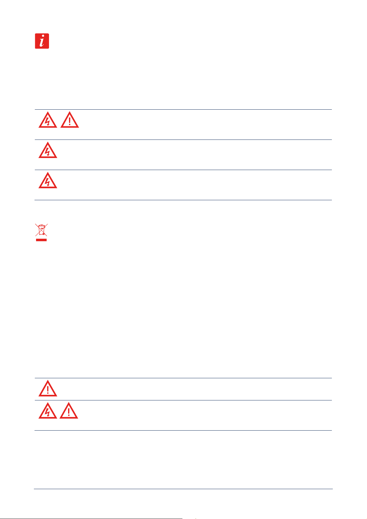
WARNING! CAUTION! To prevent the risk of fire or electric shock, never expose this
product to rain or humidity.
WARNING! To prevent electric shock hazard, do not connect to mains power supply while grille
is removed.
WARNING! to reduce the risk of electric shock, do not disassemble this product unless you are
qualified. Refer servicing to qualified service personnel.
CORRECT DISPOSAL OF THIS PRODUCT
This product should be handed over to an authorized collection site for recycling waste electrical and electronic equipment
(EEE). Improper handling of this type of waste could have a possible negative impact on the environment and human
health due to potentially hazardous substances that are generally associated with EEE. At the same time, your cooperation
in the correct disposal of this product will contribute to the effective usage of natural resources. For more information
about where you can drop off your waste equipment for recycling, please contact your local city office, waste authority or
your household waste disposal service.
CARE AND MAINTENANCE
To ensure a long-life service, this product should be used following these advices:
- If the product is intended to be set up outdoors, be sure it is under cover and protected to rain and moisture.
- If the product needs to be used in a cold environment, slowly warm up the voice coils by sending a low-level signal
for about 15 minutes before sending high-power signals.
- Always use a dry cloth to clean the exterior surfaces of the product and always do it when the power is turned off.
CAUTION: to avoid damaging the exterior finishes do not use cleaning solvents or abrasives.
WARNING! CAUTION! For powered products, do cleaning only when the power is turned
off.
FCC NOTES
This equipment has been tested and found to comply with the limits for a Class A digital device, pursuant to Part 15 of
the FCC Rules. These limits are designed to provide reasonable protection against harmful interference when the
equipment is operated in a commercial environment. This equipment generates, uses, and can radiate radio frequency

7
energy, and if it is not installed and used in accordance with the instruction manual, it may cause harmful interference to
radio communications. Operation of this equipment in a residential area is likely to cause harmful interference, in which
case the user will be required to correct the interference at his own expense.
Modifications: Any modifications made to this device that are not approved by RCF may void the authority granted to
the user by the FCC to operate this equipment.

8
RCF S.p.A. thanks you for purchasing this product, which has been designed to guarantee reliability and
high performance.
DESCRIPTION
QPS Series offers a range of four-channels professional amplifiers that combines high quality performance and reliability
with the latest power amplifications technologies. This high value design offers, in compact 2 rack unit space, the sound
quality and the durability of class HD amplifiers with the innovation of the latest power devices available:
- QPS 10K can deliver up to 4 x 2500 W @ 2 ohm;
- QPS 6.0K can deliver up to 4 x 1500 W @ 2 ohm.
Thanks to its high efficiency heat sinks and variable speed fans, QPS series amplifiers can withstand the hardest heat
conditions ensuring great reliability.
MAIN FEATURES
- Independent gain control
- Signal / clip and faults indicators
- Channels A and C XLR output link
- Mono and bridge mode
- SPEAKON output connectors
- Extensive protective circuits
UNPACKING AND INSTALLATION
Check the carton box and its contents and if there is any sign of damage (should the amplifier be damaged, immediately
inform your local distributor / dealer and the forwarder). It is always advisable to keep the packing materials, even if the
amplifier has arrived in good condition. Input and output cables are not included.
Each amplifier needs 2 units of a standard 19” rack cabinet.
Four holes for rack mounting are on the front panel ears.
Rear mounting ears give additional support.
AMPLIFIERS SHOULD NOT BE INSTALLED IN A PLACE WITH:
- too high temperature, dust or excessive humidity;
- exhaust air ventilators;
- permanent vibrations;
- high-intensity electromagnetic fields (due to transformers, transmitters, etc.).
9
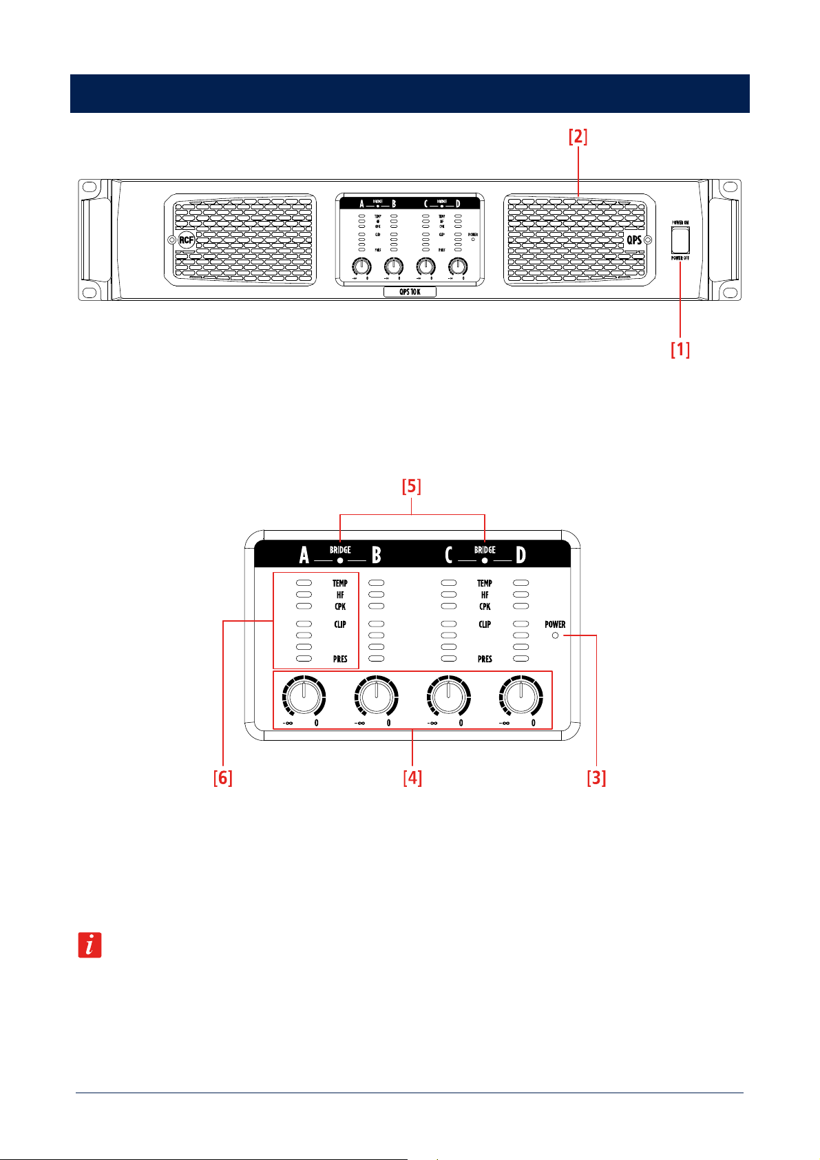
FRONT PANEL
[1] POWER SWITCH. Before switching the amplifier on, check all cables and turn fully counterclockwise all the four
channel level controls [4].
[2] Removable grill with dust protection foam.
[3] POWER LED. GREEN. When lit, the amplifier is switched on.
[4] GAIN CONTROLS (for each channel), to adjust the output level of the respective amplifier channels. Turn clockwise
to increase the output level (0 dB = max. level), turn counterclockwise to decrease. Set the control of an unused channel
fully counterclockwise.
If channels A and B are bridged, use the channel A control only. If channels C and D are bridged, use the channel C
control only.
[5] BRIDGE LEDs. YELLOW. When lit, they indicate channels A and B, or C and D are bridged. The same information is
available also on the rear panel.
10
[6] LEDs BAR (for each channel).
PRES
GREEN. When lit, it indicates the signal presence at the respective input.
Signal level is represented by the first three leds in the lower part of the bar.
CLIP
YELLOW. It blinks when the signal level reaches the clipping point, causing the limiter intervention
on the respective channel. If it is steady lit, the input signal level is excessive and should be reduced.
CPK
RED. If steady lit: load having a too low impedance / short circuit detected. The respective output is
muted.
HF
RED. If steady lit: high frequency protection insertion. The respective output is muted.
TEMP
RED. When lit, it indicates the internal protection intervention due to thermal drift. The respective
channel is muted.
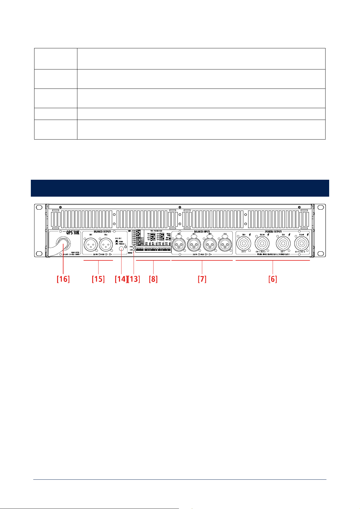
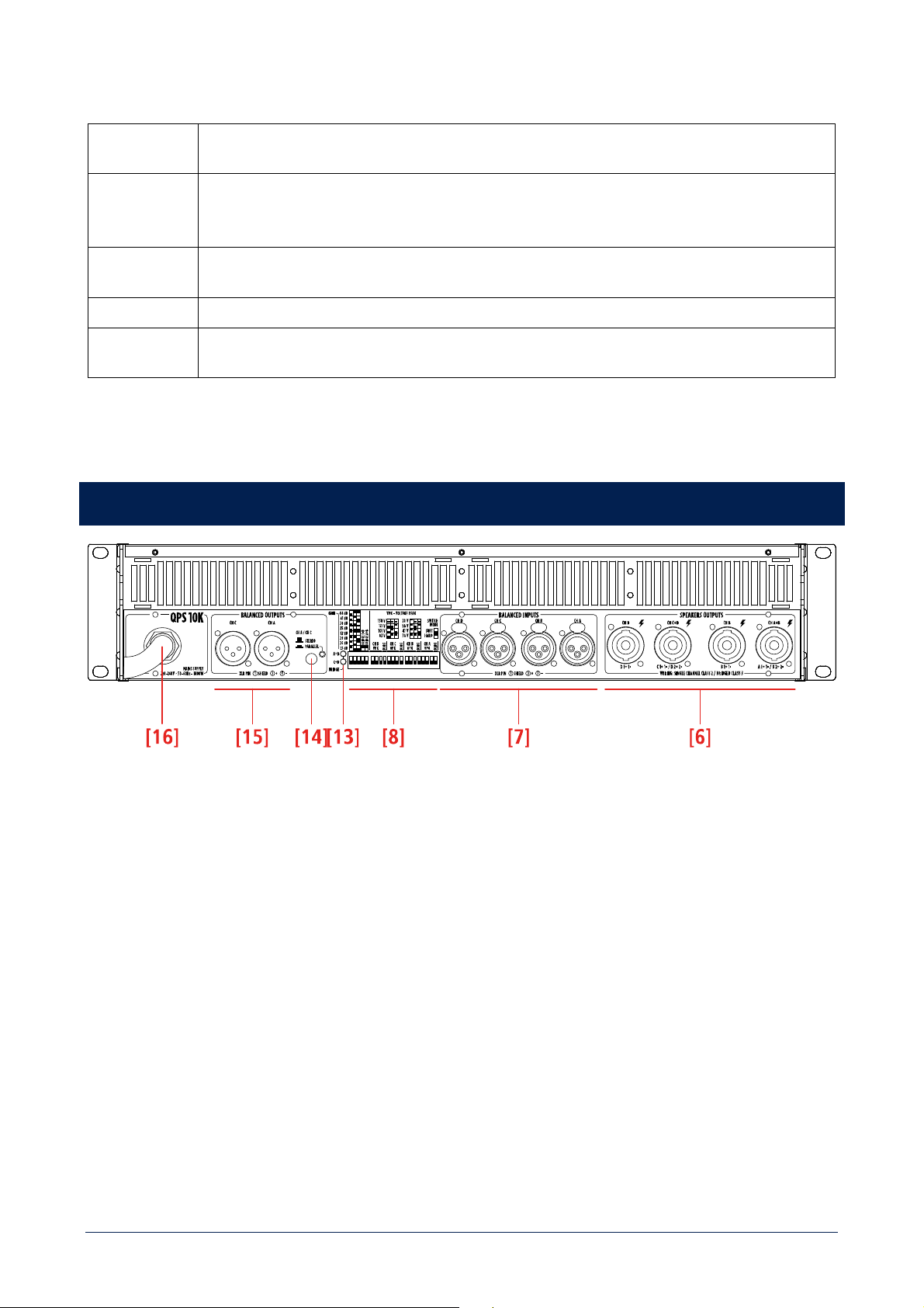
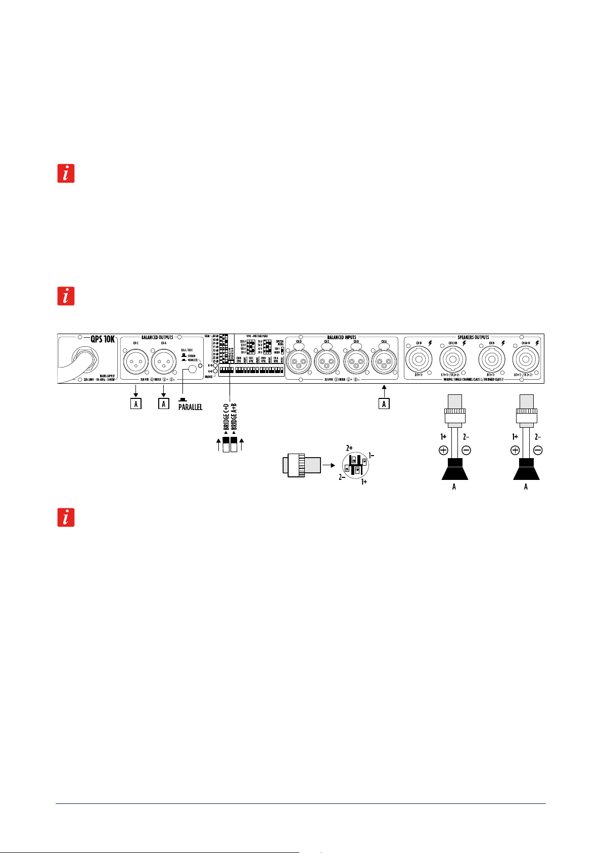
REAR PANEL
[6] CHANNELS SPEAKERS OUTPUTS. SPEAKON connector. See ‘Operation modes’ and ‘SPEAKON connector wiring’
manual sections.
[7] CHANNELS BALANCED AUDIO INPUT. Female XLR connector.
11
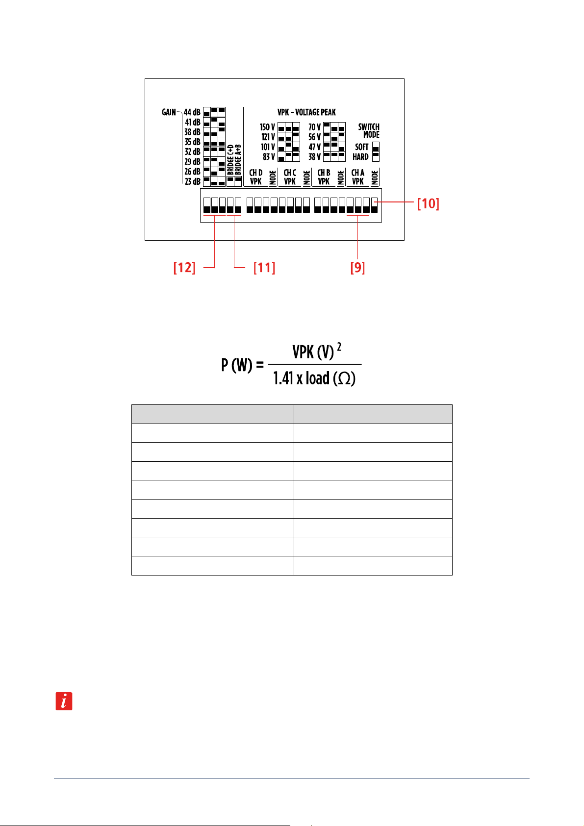
[8] DIP-SWITCH SETTINGS AREA.
[9] VPK - VOLTAGE PEAK LIMITER setting (for each channel). Three dip-switches allow to set the maximum output
voltage peak for each channel among eight values. it makes possible to reduce the channel power according to connected
speakers. Max power value can be calculated using the formula:
4 INDEPENDENT CHANNELS CHANNELS BRIDGED
150 V 300 V
121 V 242 V
101 V 202 V
83 V 166 V
70 V 140 V
56 V 112 V
47 V 94 V
38 V 76 V
[10] MODE. Select the VPK function operation and can be set on HARD (recommended for subwoofers and low-frequency
transducers) or SOFT (recommended for mid and high frequency transducers).
[11] BRIDGE A+B AND C+D SWITCHES. If set to ON, channels A and B (and/or channels C+D) are bridged (the
respective led [7] lights up). Leave it on OFF for normal two channels operation. See the ‘Operation modes’ manual
section.
Important: make sure the amplifier is turned off before setting this switch.
[12] COMMON GAIN SETTING. Three dip-switches allow to set the common gain for all the four channels, from +23
dB to +44 dB (3 dB steps).
12
[13] BRIDGE LEDs (A+B) and (C+D). When lit channels A and B (and/or C+D) are bridged (see [11] BRIDGE switches).
[14] STEREO / PARALLEL SWITCH. See the ‘Operation modes’ manual section.
Important: make sure the amplifier is turned off before setting this switch.
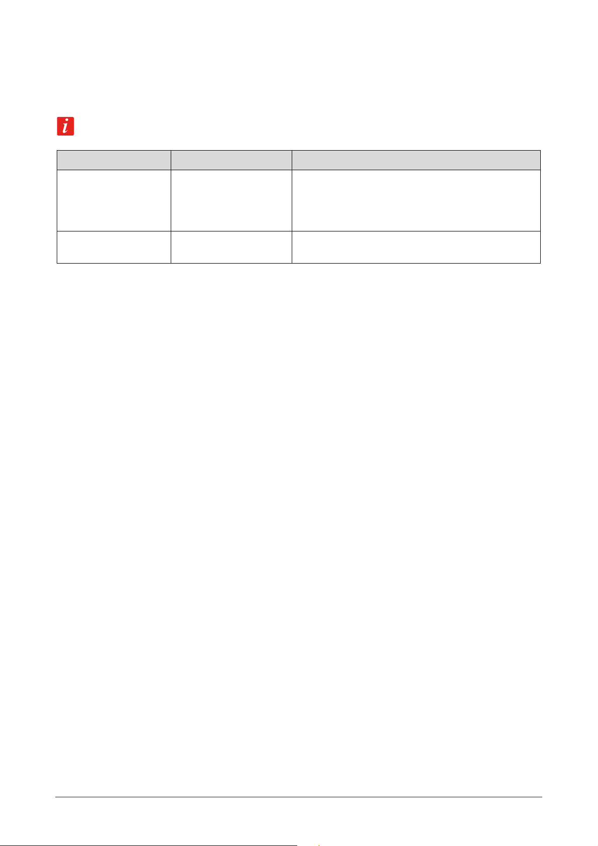
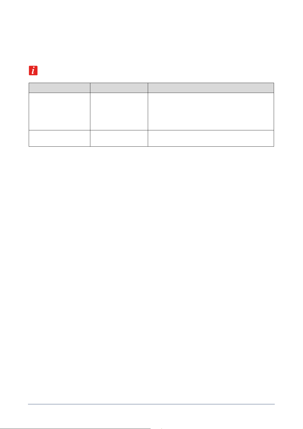
SWITCH POSITION MODE FUNCTION
OFF (released)
FOUR INDEPENDENT
CHANNELS
Standard operation: all the four channels are independent
(but in the bridge mode).
Each channel input is only sent to its respective speakers’
and balanced outputs.
ON (pushed) PARALLEL INPUTS A AND
C TO ALL OUTPUTS
Inputs A or C sent to all the speakers’ and balanced
outputs.
[15] BALANCED AUDIO OUTPUT (CH A, CH C). Male XLR connector.
[16] POWER CORD. Connect the power cord only to a mains socket outlet with a protective earthing connection.
13
OPERATION MODES
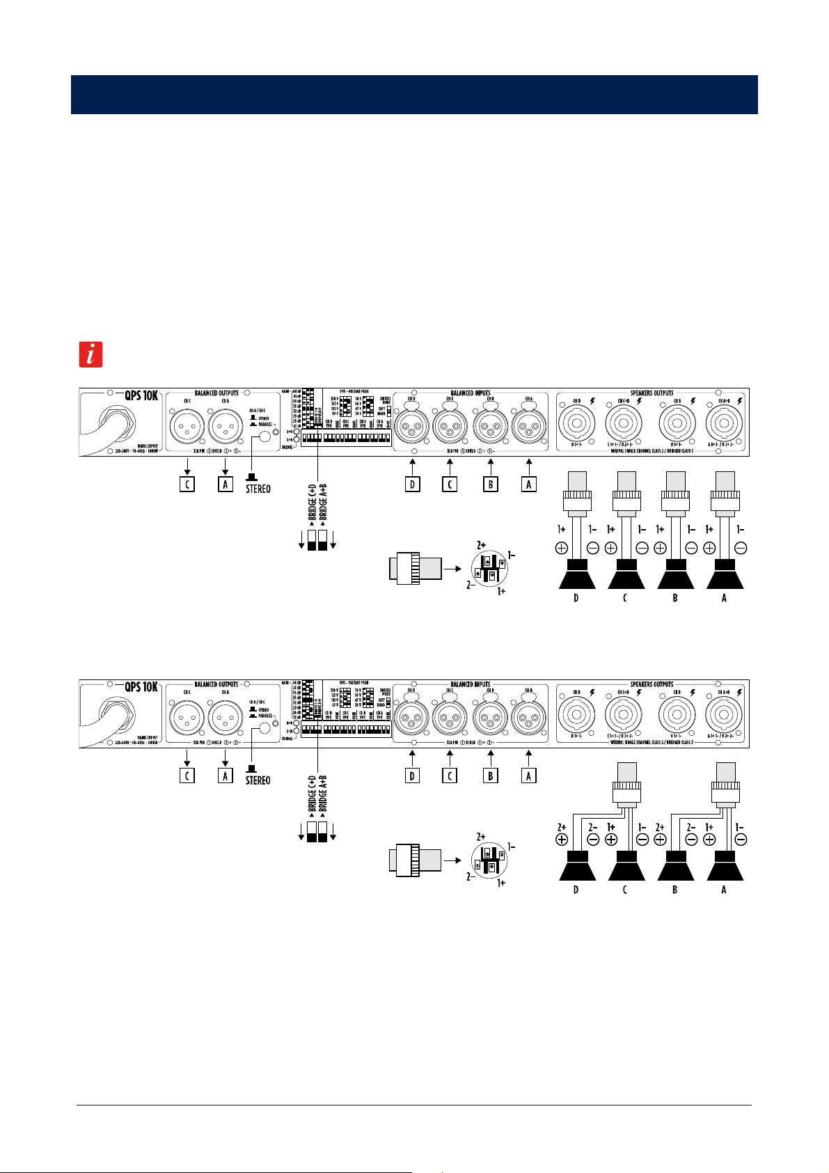
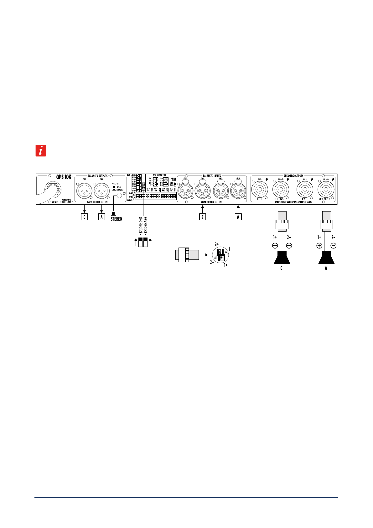
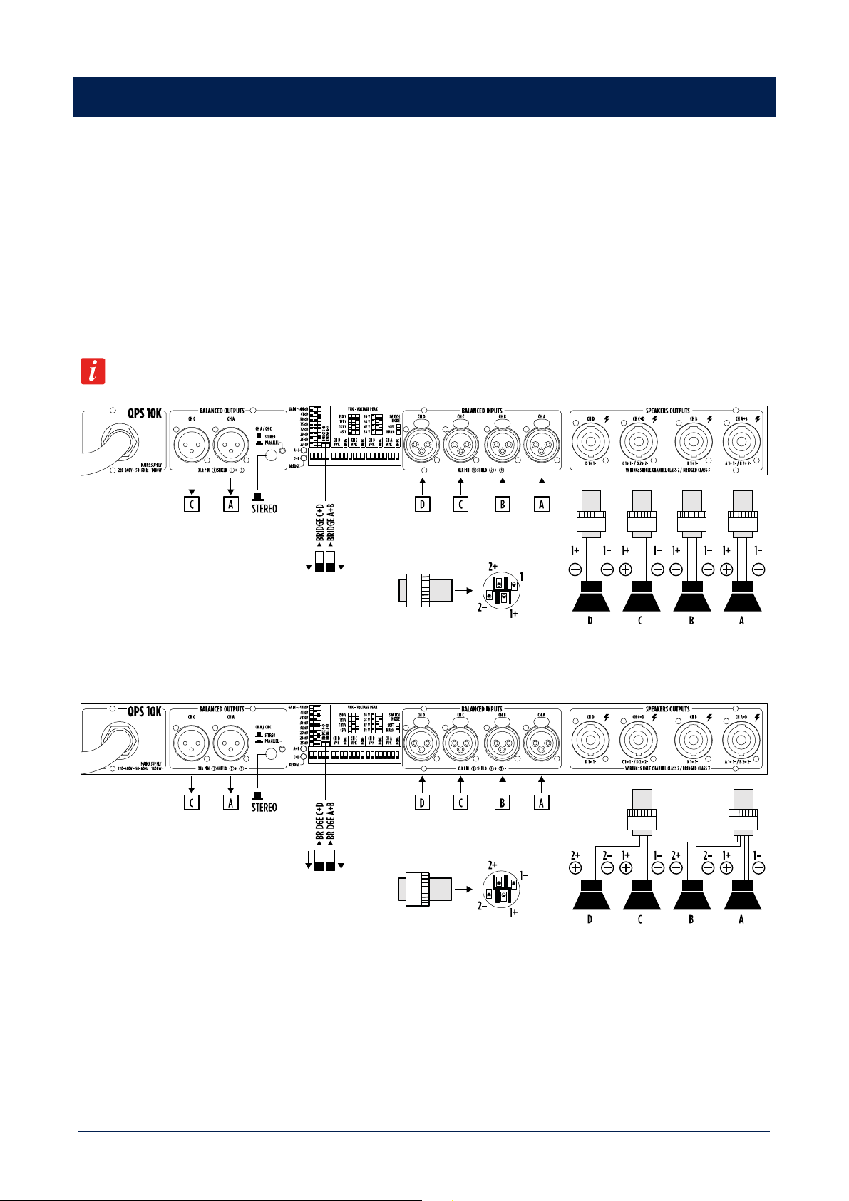
FOUR INDEPENDENT CHANNELS
Make sure the amplifier is switched off before setting:
- BRIDGE A+B switch to OFF;
- BRIDGE C+D switch to OFF;
- switch [14] to STEREO.
All the four channels are independent, and each front panel level control affects its respective speakers’ output.
This mode can be used to implement four mono channels or two stereo channels configurations.
Minimum load impedance is 2 Ω on each speakers’ output.
As alternative wiring, it is possible to use just a pair of SPEAKON connectors (by using all the four pins): one for the
channels A and B, one for the channels C and D.
14
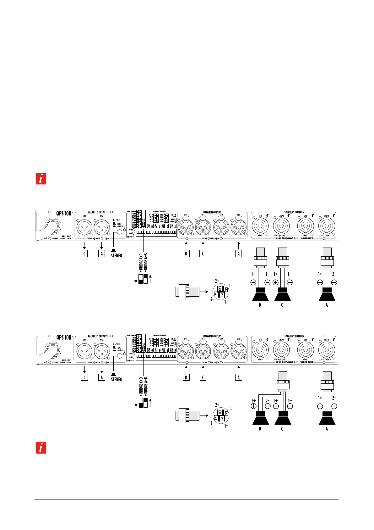
ONE BRIDGED OUTPUTS PAIR AND TWO INDIPENDENT CHANNELS
Make sure the amplifier is switched off before setting:
- BRIDGE A+B switch to ON;
- BRIDGE C+D switch to OFF;
- switch [14] to STEREO.
CHANNELS A AND B: these channels are bridged and work with the same input signal (channel A input). The result is
a doubling of the output voltage in order to get a double power (on a double impedance load).
The output level is adjusted only by the channel A front panel control (turn fully counterclockwise the channel B control).
CHANNELS C AND D: these two channels are independent, and each front panel level control affects its respective
speakers’ output.
Do NOT connect the channel B speakers’ output. Minimum load impedance is 4 Ω on channel A speakers’ output.
Pay attention to the SPEAKON wiring: pin 1+ positive, pin 2- negative. Minimum load impedance is 2 Ω on speakers’
output C and D.
As alternative wiring, it is possible to use just a SPEAKON connector (by using all the four pins) for the channels C and D.
It is alternatively possible to use channels A and B separately (BRIDGE A+B switch set to OFF) and channels C and D
bridged (BRIDGE C+D switch set to ON), by considering a mirror image of the description and connections here above
explained.
15
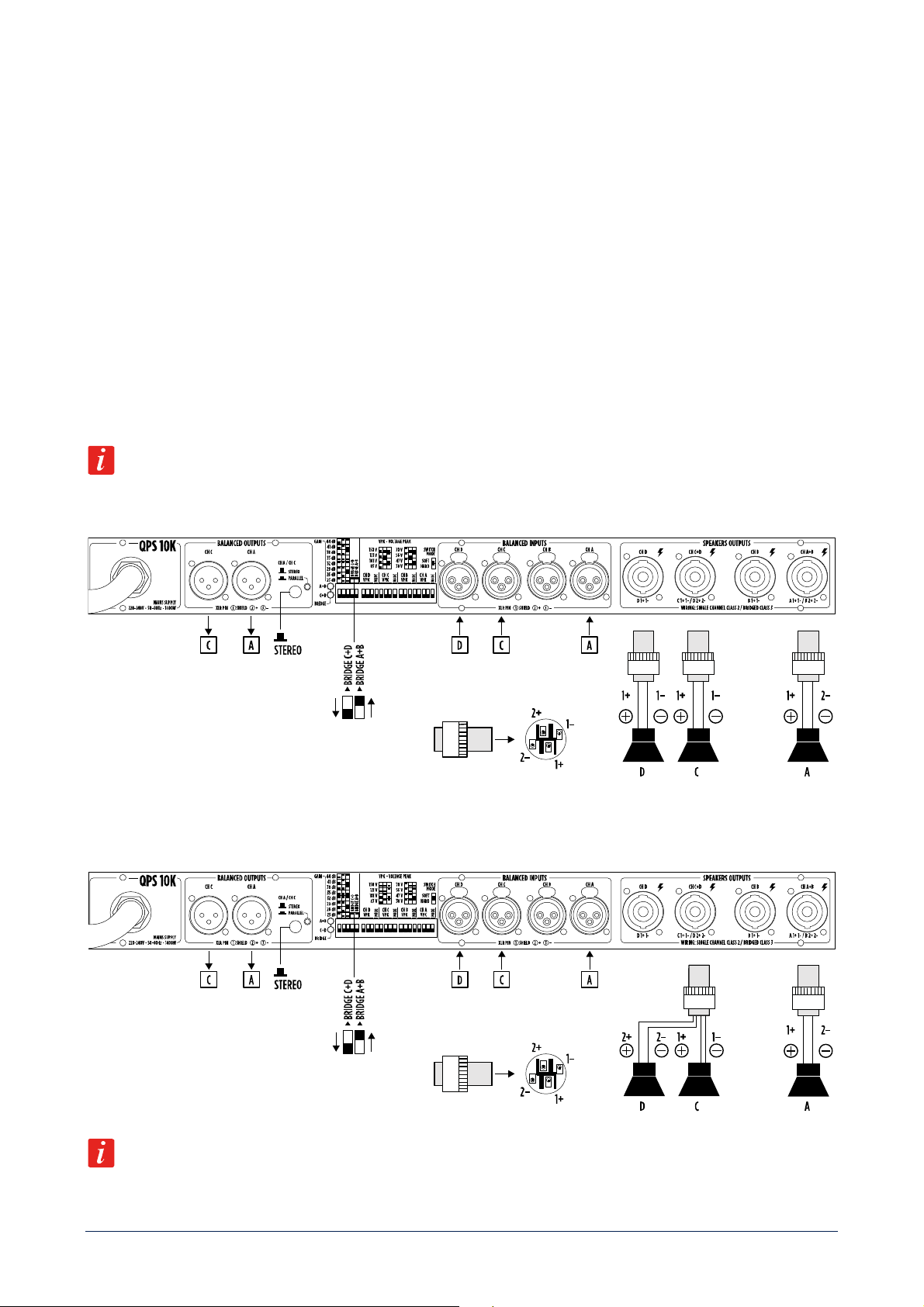
TWO BRIDGED OUTPUTS PAIRS
Make sure the amplifier is switched off before setting:
- BRIDGE A+B switch to ON;
- BRIDGE C+D switch to ON;
- switch [14] to STEREO.
All channels are bridged (two pairs): the result is a doubling of the output voltage in order to get a double power (on a
double impedance load). Each pair works with the same input signal: channel A input for A-B channels, channel C input
for C-D channels. The output levels are adjusted by the channel A and C front panel controls (turn fully counterclockwise
the channel B and D controls).
Do NOT connect the channel B and D speakers’ outputs. Minimum load impedance is 4 Ω per speakers’ output
channels A and C. Pay attention to the SPEAKON wiring: pin 1+ positive, pin 2- negative.
16
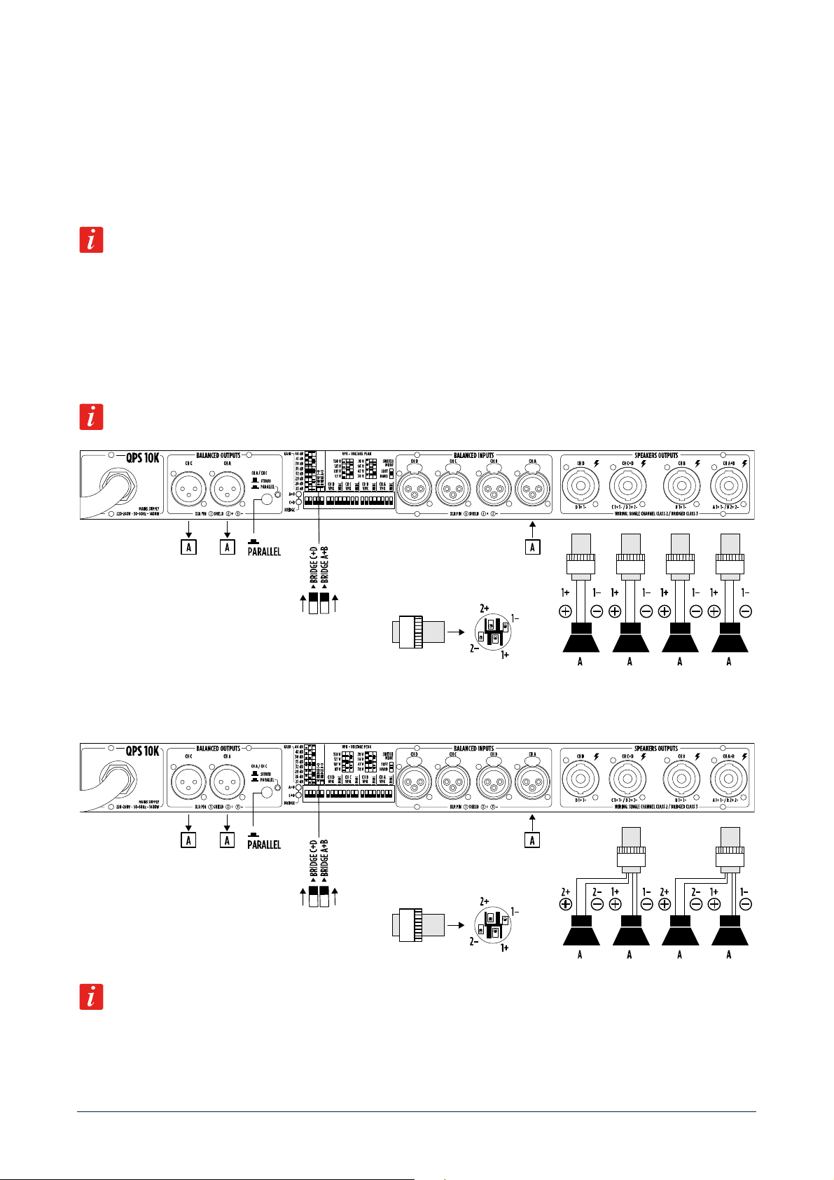
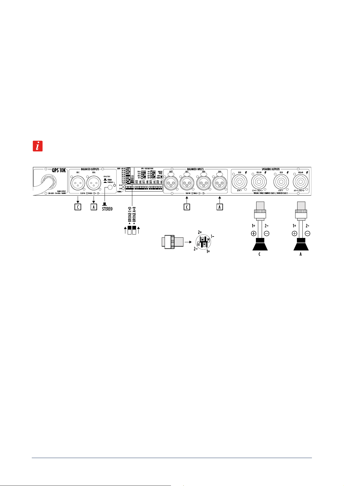
SAME INPUT SIGNAL TO ALL THE FOUR CHANNELS
Make sure the amplifier is switched off before setting:
- BRIDGE A+B switch to ON;
- BRIDGE C+D switch to ON;
- switch [14] to PARALLEL.
In PARALLEL mode connect input A or input C only. Do not used them simultaneously.
This mode can be used to send the same input signal to all the four speakers’ outputs. Each front panel level control
affects its respective speakers’ output.
In this configuration, single channel maximum power is available on each speakers’ output, despite the BRIDGE command
is activated.
Minimum load impedance is 2 Ω on each speakers’ output.
As alternative wiring, it is possible to use just a pair of SPEAKON connectors (by using all the four pins): one for the
channels A and B, one for the channels C and D.
The same configuration can be done using input C instead of input A.
17
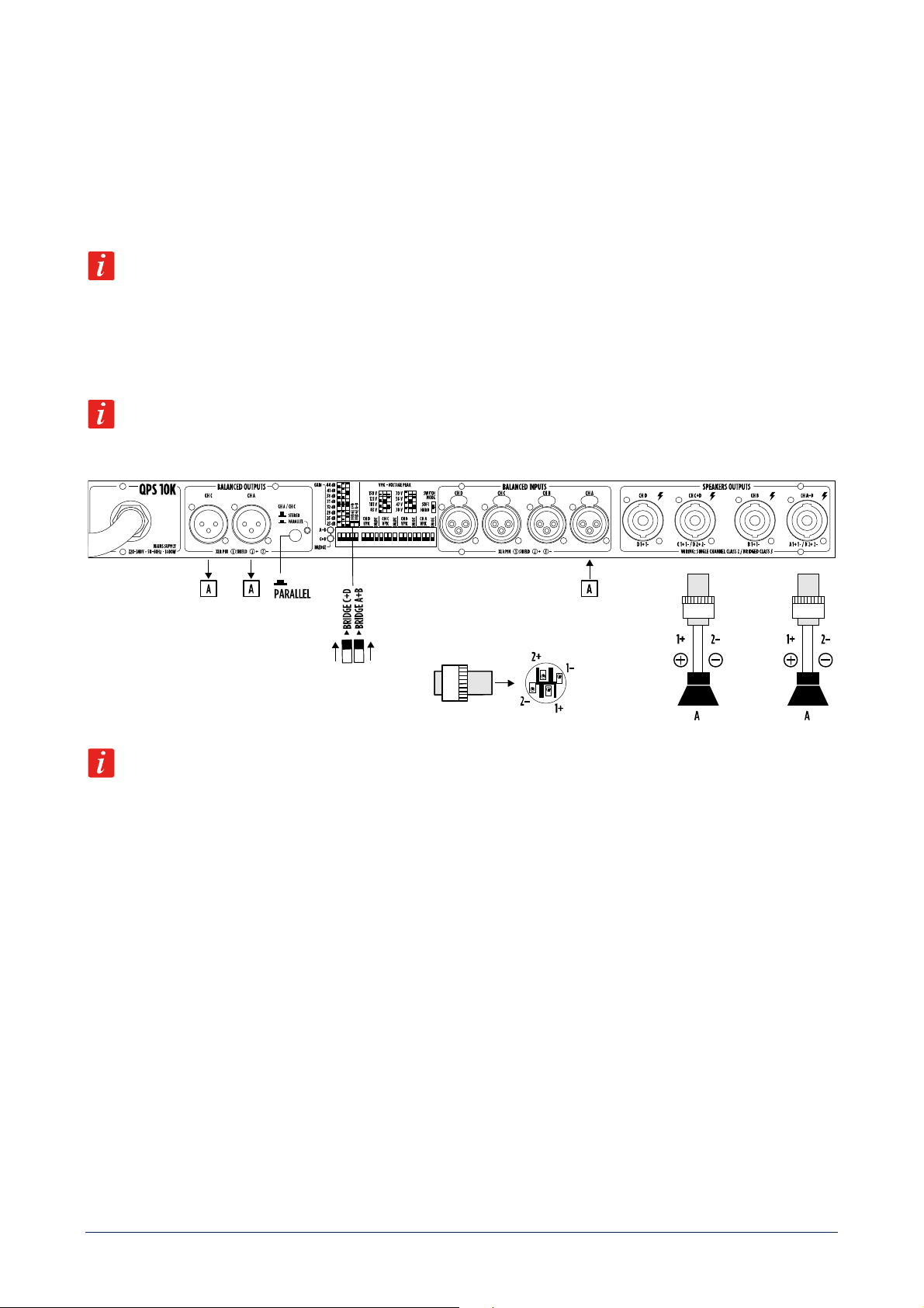
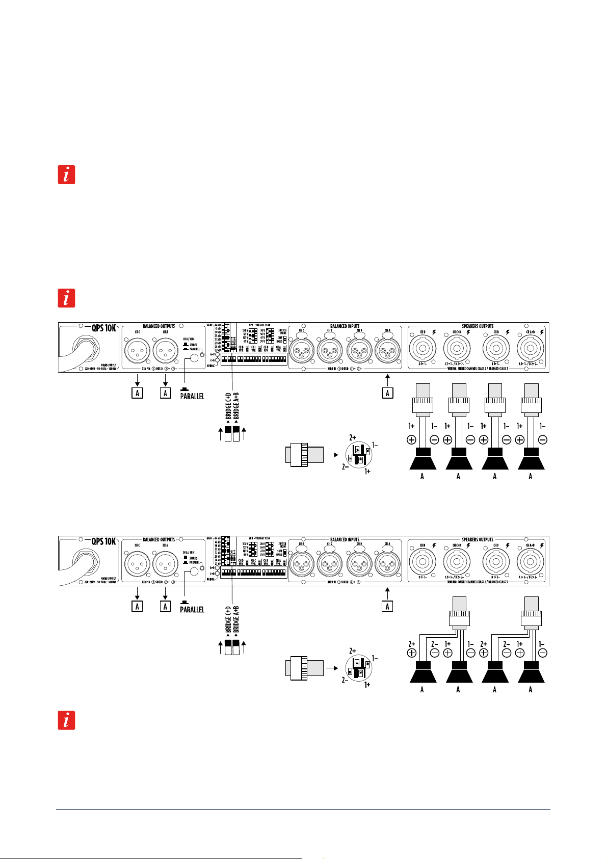
SAME INPUT SIGNAL TO BRIDGED OUTPUTS PAIRS
Make sure the amplifier is switched off before setting:
- BRIDGE A+B switch to ON;
- BRIDGE C+D switch to ON;
- switch [14] to PARALLEL.
In PARALLEL mode connect input A or input C only. Do not used them simultaneously.
All channels are bridged (two pairs): the result is a doubling of the output voltage in order to get a double power (on a
double impedance load). Both pairs work with the same channel A input. The output levels are adjusted by the channel
A and C front panel controls (turn fully counterclockwise the channel B and D controls).
Do NOT connect the channel B and D speakers’ outputs. Minimum load impedance is 4 Ω per speakers’ output
channels A and C. Pay attention to the SPEAKON wiring: pin 1+ positive, pin 2- negative.
The same configuration can be done using input C instead of input A.
18
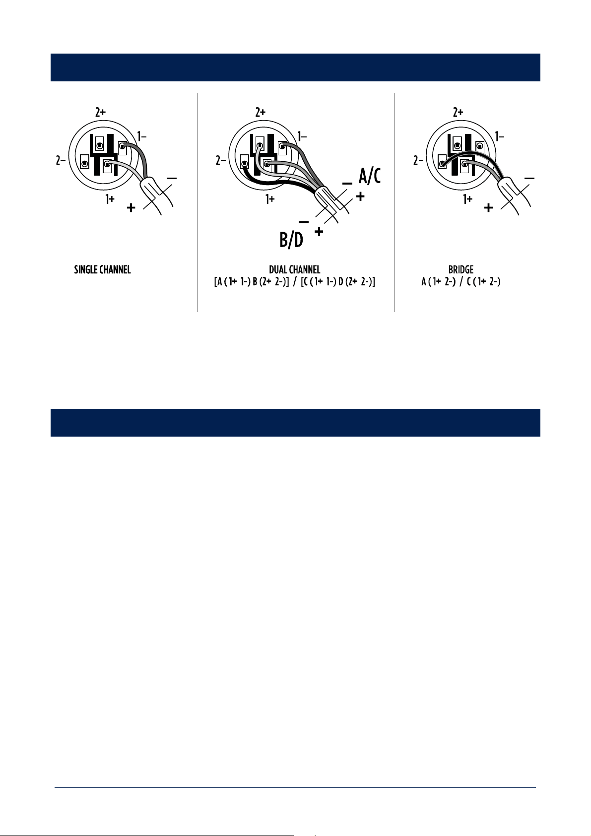
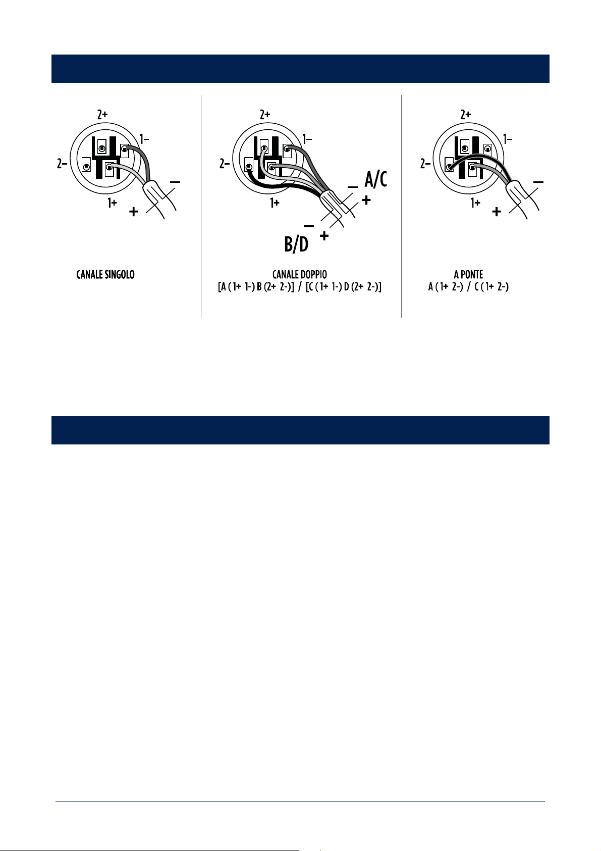
SPEAKON CONNECTORS WIRING
COOLING REQUIREMENTS
QPS 10K and QPS 6.0K have a forced air cooling system to maintain a low operating temperature.
Make sure there is enough space in the front (and all around) of all amplifiers.
If amplifiers are rack-mounted, do not use doors or covers on the front and the rear of rack cabinets.

19
AVVERTENZE PER LA SICUREZZA
I simboli utilizzati in questo documento notificano importanti istruzioni operative e avvertimenti che devono essere seguiti
attentamente.
CAUTELA
Importante istruzione operativa: notifica un pericolo che potrebbe
danneggiare il prodotto, compresa la perdita di dati.
ATTENZIONE
Avvertimento importante riguardante l’uso di voltaggi pericolosi e il
potenziale rischio di shock elettrico, lesioni personali o morte.
NOTE IMPORTANTI
Informazioni utili e rilevanti sull’argomento.
SUPPORTI, TROLLEY
E CARRRELLI
Informazioni riguardanti l’utilizzo di supporti, trolley e carrelli. Suggerisce di
muovere con estrema cautela e di non inclinare il carico.
SMALTIMENTO
Questo simbolo indica che il prodotto non deve essere smaltito con i rifiuti
ordinari, così come indicato nella direttiva WEEE (2012/19/ EU) e nelle
normative nazionali in vigore.
NOTE IMPORTANTI
Questo manuale contiene informazioni importanti sull’uso corretto e sicuro del dispositivo. Prima di collegare e utilizzare
questo prodotto, leggere attentamente questo manuale di istruzioni e tenerlo a portata di mano per riferimenti futuri. Il
manuale deve essere considerato parte integrante di questo prodotto e deve accompagnarlo in caso di cambio proprietà
come riferimento per la corretta installazione e utilizzo nonché per le precauzioni di sicurezza. RCF S.p.A. non si assume
alcuna responsabilità per l’installazione e / o l’uso errati di questo prodotto.
PRECAUZIONI DI SICUREZZA
1. Tutte le precauzioni, in particolare quelle di sicurezza, devono essere lette con particolare attenzione, in quanto
forniscono informazioni importanti.
2. Alimentazione principale da rete elettrica
a. La tensione di rete è sufficientemente elevata da comportare un rischio di folgorazione; installare e collegare questo
prodotto prima di collegarlo.
b. b. Prima di accendere, assicurarsi che tutti i collegamenti siano stati eseguiti correttamente e che la tensione della
rete corrisponda alla tensione indicata sulla targhetta dei dati sull’unità, in caso contrario, contattare il rivenditore
RCF.
c. Le parti metalliche dell’unità sono messe a terra attraverso il cavo di alimentazione. Un apparecchio con costruzione
di CLASSE I deve essere collegato a una presa di corrente con un collegamento di terra di protezione.
d. Proteggere il cavo di alimentazione da danni; assicurarsi che sia posizionato in modo tale da non poter essere
calpestato o schiacciato da oggetti.
e. Per evitare il rischio di scosse elettriche, non aprire mai questo prodotto: non sono previste parti interne alle quali
l’utente debba accedere.
f. Fare attenzione: nel caso di un prodotto provvisto solo di connettori POWERCON e senza cavo di alimentazione,
congiuntamente ai connettori POWERCON tipo NAC3FCA (alimentazione) e NAC3FCB (alimentazione), devono
essere usati i seguenti cavi di alimentazione conformi alla norma nazionale:
- EU: cavo di tipo H05VV-F 3G 3x2.5 mm2 - Standard IEC 60227-1

20
- JP: cavo di tipo VCTF 3x2 mm2; 15Amp/120V~ - Standard JIS C3306
- US: cavo di tipo SJT/SJTO 3x14 AWG; 15Amp/125V~ - Standard ANSI/UL 62
3. Assicurarsi che nessun oggetto o liquido penetri in questo prodotto poiché ciò potrebbe causare un corto circuito.
Questo apparecchio non deve essere esposto a gocciolamenti o spruzzi. Nessun oggetto riempito di liquido, come
vasi, deve essere posizionato su questo apparecchio. Nessuna fiamma libera (come candele accese) deve essere
posizionata su questo apparecchio.
4. Non tentare mai di eseguire operazioni, modifiche o riparazioni non espressamente descritte nel presente manuale.
Contattare il centro di assistenza autorizzato o personale qualificato qualora si verifichi una delle seguenti condizioni:
- Il prodotto non funziona (o funziona in modo anomalo).
- Il cavo di alimentazione è stato danneggiato.
- Oggetti o liquidi sono entrati nell’unità.
- Il prodotto ha subìto un forte urto.
5. Se questo prodotto non viene utilizzato per un lungo periodo, scollegare il cavo di alimentazione.
6. Se questo prodotto inizia a emettere strani odori o fumo, spegnerlo immediatamente e scollegare il cavo di
alimentazione.
7. Non collegare questo prodotto ad apparecchiature o accessori non previsti. Per l’installazione sospesa, utilizzare solo
i punti di ancoraggio dedicati e non tentare di appendere questo prodotto utilizzando elementi non idonei o non
specifici per questo scopo. Verificare inoltre l’idoneità della superficie di supporto a cui è ancorato il prodotto (parete,
soffitto, struttura, ecc.) a dei componenti utilizzati per il fissaggio (tasselli, viti, staffe non fornite da RCF ecc.) che
devono garantire sicurezza del sistema / installazione nel tempo, anche considerando, ad esempio, le vibrazioni
meccaniche normalmente generate dai trasduttori. Per evitare il rischio di caduta dell’apparecchiatura, non impilare
più unità di questo prodotto a meno che questa possibilità non sia specificata nel manuale dell’utente.
8. RCF S.p.A. raccomanda vivamente che questo prodotto sia installato solo da installatori professionisti qualificati (o
aziende specializzate) che possono garantire la corretta installazione e certificarlo secondo le normative vigenti.
L’intero sistema audio deve essere conforme agli standard e alle normative vigenti in materia di sistemi elettrici.
9. Supporti, trolley e carrelli.
L’apparecchiatura deve essere utilizzata, ove necessario, solo su supporti, trolley e carrelli consigliati dal
produttore. L’apparecchiatura / supporto / carrello deve essere spostata con estrema cautela. Arresti improvvisi,
eccessiva spinta e pavimenti irregolari possono causarne il ribaltamento. Non inclinare mai.
10. Vi sono numerosi fattori meccanici ed elettrici da considerare quando si installa un sistema audio professionale (oltre
a quelli strettamente acustici, come la pressione del suono, gli angoli di copertura, la risposta in frequenza, ecc.).
11. Perdita dell’udito. L’esposizione a livelli sonori elevati può causare la perdita permanente dell’udito. Il livello di
pressione acustica che porta alla perdita dell’udito è diverso da persona a persona e dipende dalla durata
dell’esposizione. Per prevenire un’esposizione potenzialmente pericolosa a livelli elevati di pressione acustica,
chiunque sia esposto a questi livelli dovrebbe usare adeguati dispositivi di protezione. Quando viene utilizzato un
trasduttore in grado di produrre alti livelli sonori, è quindi necessario indossare tappi per le orecchie o cuffie protettive.
Vedere le specifiche tecniche del manuale per conoscere il livello massimo di pressione sonora.
PRECAUZIONI OPERATIVE
- Posizionare questo prodotto lontano da qualsiasi fonte di calore e garantire sempre un’adeguata circolazione dell’aria
attorno ad esso.
- Non sovraccaricare questo prodotto per molto tempo.
- Non forzare mai gli elementi di controllo (tasti, manopole, ecc.).
- Non utilizzare solventi, alcool, benzene o altre sostanze volatili per pulire le parti esterne di questo prodotto.
21
NOTE IMPORTANTI
Per evitare il verificarsi di disturbi sui cavi di segnale in linea, utilizzare solo cavi schermati ed evitare di avvicinarli a:
- Apparecchiature che producono campi elettromagnetici ad alta intensità
- Cavi di alimentazione
- Linee di altoparlanti
ATTENZIONE! CAUTELA! Per evitare il rischio di incendi o scosse elettriche, non esporre
mai questo prodotto a pioggia o umidità.
ATTENZIONE! Per evitare il rischio di scosse elettriche, non collegare all’alimentazione di rete
mentre la griglia è rimossa.
WARNING! Per ridurre il rischio di scosse elettriche, non smontare questo prodotto se non si è
qualificati. Per l’assistenza rivolgersi a personale di assistenza qualificato.
SMALTIMENTO CORRETTO DEL PRODOTTO
Questo prodotto deve essere consegnato a un sito di raccolta autorizzato per il riciclaggio di apparecchiature elettriche ed
elettroniche (AEE). Una manipolazione impropria di questo tipo di rifiuti potrebbe avere un possibile impatto negativo
sull’ambiente e sulla salute umana a causa di sostanze potenzialmente pericolose che sono generalmente associati alle
AEE. Allo stesso tempo, la vostra collaborazione per il corretto smaltimento di questo prodotto contribuirà all’utilizzo
efficace delle risorse naturali. Per ulteriori informazioni su dove sia possibile scaricare le attrezzature per il riciclaggio, si
prega di contattare l’ufficio comunale locale, l’autorità competente per i rifiuti o il servizio di smaltimento dei rifiuti
domestici.
CURA E MANUTENZIONE
Per garantire un servizio di lunga durata, questo prodotto deve essere utilizzato seguendo questi consigli:
- Se il prodotto deve essere installato all’aperto, assicurarsi che sia coperto e protetto da pioggia e umidità.
- Se il prodotto deve essere utilizzato in un ambiente freddo, riscaldare lentamente le bobine vocali inviando un segnale
di basso livello per circa 15 minuti prima di inviare segnali ad alta potenza.
- Utilizzare sempre un panno asciutto per pulire le superfici esterne del prodotto e farlo sempre quando l’alimentazione
è spenta.
CAUTELA! Per evitare di danneggiare le finiture esterne non utilizzare solventi per la pulizia o
abrasivi.
ATTENZIONE! CAUTELA! Per i prodotti alimentati, eseguire la pulizia solo quando
l’alimentazione è spenta.

22
NOTE FCC
Questa apparecchiatura è stata testata ed è risultata conforme ai limiti per un dispositivo digitale di Classe A, ai sensi
della Parte 15 delle norme FCC. Questi limiti sono progettati per fornire una protezione ragionevole contro interferenze
dannose quando l'apparecchiatura viene utilizzata in un ambiente commerciale. Questa apparecchiatura genera, utilizza
e può irradiare energia in radiofrequenza e, se non viene installata e utilizzata secondo il manuale di istruzioni, può causare
interferenze dannose alle comunicazioni radio. È probabile che il funzionamento di questa apparecchiatura in un'area
residenziale provochi interferenze dannose, nel qual caso l'utente dovrà correggere l'interferenza a proprie spese.
Modifiche: qualsiasi modifica apportata a questo dispositivo che non sia approvata da RCF può annullare l'autorizzazione
concessa all'utente dalla FCC di utilizzare questa apparecchiatura.

23
RCF S.p.A. Vi ringrazia per l’acquisto di questo prodotto, realizzato in modo da garantirne l’affidabilità e
prestazioni elevate.
DESCRIZIONE
La serie QPS offre una gamma di amplificatori professionali a quattro canali che unisce alte prestazioni e affidabilità, con
le più nuove tecnologie nel campo dell’amplificazione. Grazie ad un design orientato all’efficienza, gli amplificatori della
serie offrono la qualità audio e l’affidabilità degli amplificatori classe HD, in un prodotto compatto di sole due unità rack
di ingombro:
- QPS 10K eroga una potenza massima di 4 x 2500 W @ 2 ohm;
- QPS 6.0K eroga una potenza massima di 4 x 1500 W @ 2 ohm.
Grazie ai dissipatori di calore ad alta efficienza e alle ventole a velocità variabile, gli amplificatori della serie QPS sono in
grado di operare con grande affidabilità anche in condizioni di temperature estreme
CARATTERISTICHE PRINCIPALI
- Controlli di Guadagno indipendenti per ciascun canale
- Indicatori di guasto e clipping del segnale
- Link per I canali A e C su connettore XLR
- Modalità di funzionamento mono, stereo e a ponte
- Connettori di uscita SPEAKON
- Sistema completo di protezioni interne
DISIMBALLO ED INSTALLAZIONE
Verificare se il cartone per l’imballo ed il contenuto hanno subito dei danni durante il trasporto (nel caso che l’amplificatore
sia danneggiato, informare immediatamente il rivenditore e lo spedizioniere). È sempre consigliabile tenere il materiale
d’imballo, perfino nel caso che l’amplificatore sia arrivato in buone condizioni. I cavi per gli ingressi audio e le uscite
amplificate non sono inclusi.
Ciascun amplificatore occupa 2 unità di un rack standard 19”.
Sulle alette del pannello frontale, sono presenti quattro fori per il montaggio a rack; le alette posteriori forniscono un
ulteriore supporto.
L’AMPLIFICATORE NON DEVE ESSERE POSTO IN LUOGHI CON:
- temperatura troppo elevata, polvere o umidita eccessiva;
- macchine del fumo con l’uscita orientata verso l’amplificatore;
- uscite d’aria riscaldata;
- vibrazioni permanenti;
- forti campi elettromagnetici (dovuti a trasformatori, trasmettitori, ecc.).

24
PANNELLO FRONTALE
[1] INTERRUTTORE PRINCIPALE. Prima di accendere l'amplificatore, controllare tutte le connessioni e ruotare
completamente in senso antiorario i controlli di livello [4] di tutti i quattro canali.
[2] Griglie rimovibili con spugna antipolvere.
[3] POWER LED. VERDE. Indica l'accensione dell'amplificatore.
[4] CONTROLLI DI GUADAGNO (uno per ogni canale) per la regolazione del livello d'uscita dei rispettivi canali
dell'amplificatore. Ruotarli in senso orario per aumentare i livelli d'uscita (0 dB = livello max.) od antiorario per diminuirli.
Impostare al minimo il livello di un canale inutilizzato su ruotando il controllo completamente in senso antiorario.
Se i canali A e B sono messi a ponte, usare solo il controllo del canale A; se i canali C e D sono messi a ponte, usare
solo il controllo del canale C.
[5] LED BRIDGE. GIALLI. Se accesi, indicano che i canali A e B, o C e D, sono messi a ponte. La stessa informazione è
disponibile anche sul pannello posteriore.
25
[6] BARRA LED (per ciascun canale).
PRES
VERDE. Quando acceso, indica la presenza del segnale nel rispettivo ingresso. Il livello del segnale è
rappresentato dai primi tre led nella parte inferiore della barra.
CLIP
GIALLO. Lampeggia quando il livello del segnale raggiunge il il livello massimo prima della
saturazione, causando l’intervento del limitatore interno del rispettivo canale.
Nel caso sia costantemente acceso, il livello del segnale d’ingresso è eccessivo ed andrebbe diminuito.
CPK
ROSSO. Se acceso fisso: l’impedenza del carico è troppo bassa oppure è rilevato un cortocircuito (la
rispettiva uscita è disattivata).
HF
ROSSO. Se acceso fisso: protezione alte frequenze; il rispettivo canale è disattivato.
TEMP
ROSSO. La sua accensione indica l’intervento della protezione interna a causa di una deriva termica
ed il rispettivo canale è disattivato.
PANNELLO POSTERIORE
[6] USCITE DI POTENZA verso i diffusori acustici su connettore SPEAKON. Vedere le sezioni del manuale “Modi di
funzionamento” e “Cablaggio dei connettori SPEAKON”.
[7] INGRESSI AUDIO BILANCIATI su connettore XLR femmina.

26
[8] SETTAGGI TRAMITE DIP-SWITCH.
[9] LIMITER HARDWARE - VPK (per ciascun canale). I tre dip-switch permettono l’impostazione della massima tensione
di picco d’uscita di ciascun canale, tra otto valori. In altre parole, è possibile depotenziare il canale in base ai diffusori
acustici collegati. Il valore massimo di potenza può essere calcolato con la formula:
CANALI INDIPENDENTI CANALI A PONTE
150 V 300 V
121 V 242 V
101 V 202 V
83 V 166 V
70 V 140 V
56 V 112 V
47 V 94 V
38 V 76 V
[10] MODE. Seleziona la modalità di funzionamento del limiter e può essere impostato su HARD (raccomandato per
subwoofers e altoparlanti per basse frequenze) oppure SOFT (raccomandato per altoparlanti per medie ed alte frequenze).
[11] SELETTORI BRIDGE A+B E C+D. Se impostati su ON, i canali A e B (e/o C e D) sono messi a ponte (il rispettivo
LED [7] si illumina). Lasciarlo su OFF per il funzionamento separato dei due canali. Vedere la sezione del manuale “Modi
di funzionamento”.
Importante: assicurarsi che l'amplificatore sia spento prima di effettuare la selezione.
[12] IMPOSTAZIONE DEL GUADAGNO (comune a tutti i canali). I tre dip-switch permettono di impostare il guadagno
(per tutti i quattro canali) da +23 dB a +44 dB (in passi da 3 dB). Vedere la seguente tabella e selezionare l'impostazione
più appropriata.
27
[13] LED BRIDGE (A+B) e (C+D). Se accesi i canali A e B (e/o C e D) sono messi a ponte (vedere il punto [11] : Selettori
BRIDGE).
[14] SELETTORE STEREO / PARALLEL. Vedere la sezione del manuale “Modi di funzionamento”.
Importante: assicurarsi che l'amplificatore sia spento prima di effettuare la selezione.
POSIZIONE SELETTORE MODO FUNZIONAMENTO
OFF (rilasciato) QUATTRO CANALI
INDIPENDENTI
Funzionamento standard: tutti i quattro canali sono
indipendenti (tranne se messi a “a ponte”).
Ogni ingresso (un canale) è inviato solo alla rispettiva
uscita amplificata per altoparlanti (e quella audio
bilanciata).
ON (premuto)
INGRESSI A E C IN
PARALLELO
L’ingresso A o C viene inviato a tutte le uscite altoparlanti
(e quelle audio bilanciate).
[15] USCITE AUDIO BILANCIATE (CH A e CH C) su connettore XLR maschio.
[16] CAVO DI ALIMENTAZIONE. Collegare il cavo d'alimentazione solo ad una presa di rete avente la messa a terra.
28
MODI DI FUNZIONAMENTO
QUATTRO CANALI INDIPENDENTI
Assicurarsi che l'amplificatore sia spento prima di impostare:
- il selettore BRIDGE A+B su OFF;
- il selettore BRIDGE C+D su OFF;
- il selettore [14] su STEREO.
Tutti i quattro canali sono completamente indipendenti ed ogni controllo di livello (sul pannello frontale) agisce (solo) sulla
rispettiva uscita altoparlanti.
L'impedenza minima ammessa del carico e 2 Ω per ogni uscita altoparlanti.
Come cablaggio alternativo, è possibile usare solo un paio di connettori SPEAKON (sfruttando tutti i quattro contatti): uno
per i canali A e B, uno per i canali C e D.
29
UNA COPPIA DI CANALI A PONTE E DUE CANALI INDIPENDENTI
Assicurarsi che l'amplificatore sia spento prima di impostare:
- il selettore BRIDGE A+B su ON;
- il selettore BRIDGE C+D su OFF;
- il selettore [14] su STEREO.
CANALI A e B: questi sono messi a ponte e hanno in comune lo stesso segnale d'ingresso (quello del canale A). Questo
comporta un raddoppio della tensione d'uscita per ottenere una potenza doppia (su un carico avente impedenza doppia).
Il livello d'uscita è regolabile solo dal controllo del canale A posto sul pannello frontale (ruotare completamente in senso
antiorario il controllo di livello del canale B).
CANALI C e D: sono completamente indipendenti e ciascuno dei due controlli di livello (sul pannello frontale) agisce
(solo) sulla rispettiva uscita altoparlanti.
Non collegare l'uscita altoparlanti del canale B. L'impedenza minima ammessa del carico è 4 Ω per l'uscita altoparlanti
del canale A. Prestare attenzione al cablaggio del connettore SPEAKON: 1+ positivo, 2– negativo. L'impedenza minima
ammessa del carico è 2 Ω per per le uscite altoparlanti dei canali C e D.
Come cablaggio alternativo, è possibile usare solo un paio di connettori SPEAKON (sfruttando tutti i quattro contatti): uno
per i canali A e B, uno per i canali C e D.
È ammesso usare i canali A e B separati (selettore BRIDGE A+B su OFF) ed i canali C e D a ponte (selettore BRIDGE
C+D su ON), considerando un'immagine speculare dei collegamenti e della descrizione sopra menzionata.
30
DUE COPPIE DI CANALI A PONTE
Assicurarsi che l'amplificatore sia spento prima di impostare:
- il selettore BRIDGE A+B su ON;
- il selettore BRIDGE C+D su ON;
- il selettore [14] su STEREO.
Tutti i canali sono a ponte (due coppie): questo comporta un raddoppio della tensione d'uscita per ottenere una potenza
doppia (su un carico avente impedenza doppia). Ciascuna coppia di canali ha in comune lo stesso segnale d'ingresso:
quello del canale A per la coppia A+B, quello del canale C per la coppia C+D. I livelli d'uscita sono regolabili solo dai
controlli dei canali A e C posti sul pannello frontale (ruotare completamente in senso antiorario i controlli di livello dei
canali B e D).
Non collegare le uscite altoparlanti dei canali B e D. L'impedenza minima ammessa del carico è 4 Ω per le uscite
altoparlanti A e C. Prestare attenzione al cablaggio del connettore SPEAKON: 1+ positivo, 2– negativo.
31
UN UNICO SEGNALE COMUNE A TUTTI I QUATTRO CANALI
Assicurarsi che l'amplificatore sia spento prima di impostare:
- il selettore BRIDGE A+B su ON;
- il selettore BRIDGE C+D su ON;
- il selettore [14] su PARALLEL.
Con modalità PARALLEL collegare solo l’ingresso A oppure l’ingresso C. Non utilizzare i due ingressi
simultaneamente.
Questa modalità si utilizza per inviare lo stesso segnale di ingresso a tutte e quattro le uscite altoparlanti. Ogni controllo
di livello agisce solo sulla rispettiva uscita altoparlanti.
In questa configurazione la potenza disponibile su ciascuna uscita è pari a quella del singolo canale, nonostante
l’attivazione dei comandi BRIDGE.
L'impedenza minima ammessa del carico e 2 Ω per ogni uscita altoparlanti.
Come cablaggio alternativo, è possibile usare solo un paio di connettori SPEAKON (sfruttando tutti i quattro contatti): uno
per i canali A e B, uno per i canali C e D.
La stessa configurazione può essere implementata utilizzando l’ingresso C anziché l’ingresso A.
32
UN UNICO SEGNALE COMUNE A COPPIE DI CANALI A PONTE
Assicurarsi che l'amplificatore sia spento prima di impostare:
- il selettore BRIDGE A+B su ON;
- il selettore BRIDGE C+D su ON;
- il selettore [14] su PARALLEL.
Con modalità PARALLEL collegare solo l’ingresso A oppure l’ingresso C. Non utilizzare i due ingressi
simultaneamente.
Tutti i canali sono a ponte (due coppie): questo comporta un raddoppio della tensione d'uscita per ottenere una potenza
doppia (su un carico avente impedenza doppia). Entrambe le coppie di canali hanno in comune lo stesso segnale
d'ingresso, quello del canale A. I livelli d'uscita sono regolabili dai controlli dei canali A e C posti sul pannello frontale
(ruotare completamente in senso antiorario i controlli di livello dei canali B e D).
Non collegare le uscite altoparlanti dei canali B e D. L'impedenza minima ammessa del carico è 4 Ω per le uscite
altoparlanti A e C. Prestare attenzione al cablaggio del connettore SPEAKON: 1+ positivo, 2– negativo.
La stessa configurazione può essere implementata utilizzando l’ingresso C anziché l’ingresso A.
33
CABLAGGIO DEI CONNETTORI SPEAKON
VENTILAZIONE
Gli amplificatori QPS 10K and QPS 6.0K hanno un sistema di raffreddamento con ventilazione forzata per mantenere una
bassa temperatura di funzionamento.
Assicurarsi che vi sia spazio sufficiente sia davanti il pannello frontale sia tutt'intorno agli amplificatori.
Se gli amplificatori sono montati in un armadio rack, non utilizzare porte (od altre coperture) sia sul lato anteriore sia su
quello posteriore.
34
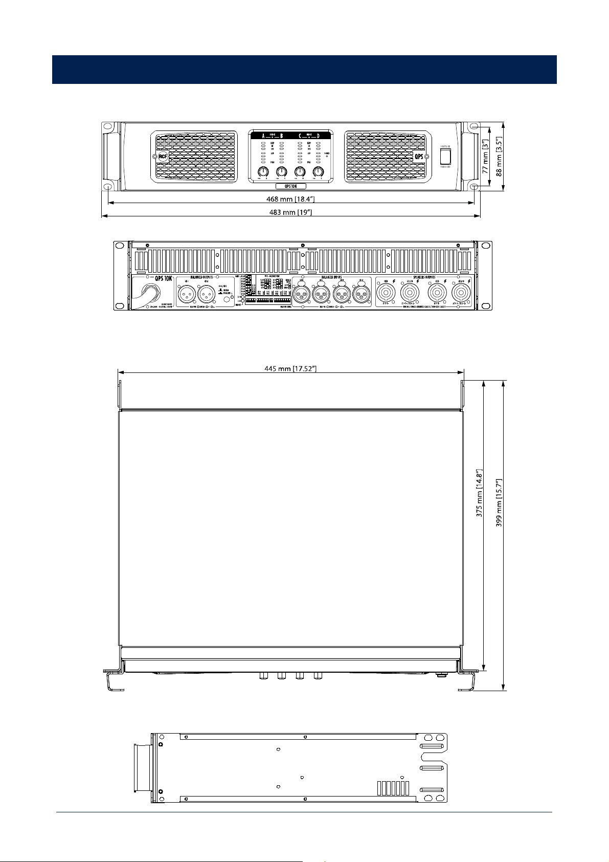
DIMENSIONS / DIMENSIONI

35
SPECIFICATIONS / SPECIFICHE TECNICHE
QPS 10K QPS 6.0K
Amplifier specifications
Amplifier Class: HD HD
Number of channels: 4 4
Power output per channel (@ 2 ohm): 2500W RMS 1500W
Power output per channel (@ 4 ohm): 2200 W RMS 1300 W
Power output per channel (@ 8 ohm): 1400 W RMS 700 W
Power output (bridged @ 4 ohm): 5000 W RMS 3000 W
Power output (bridged @ 8 ohm): 4400 W RMS 2600 W
Frequency Response (-3dB): 20 Hz ÷ 20000 Hz 20 Hz ÷ 20000 Hz
Signal/noise rate (”A” weighted) >110 dB >110 dB
Crosstalk <70 dB <70 dB
Distortion (THD+N) @ 1 kHz nominal power: <0.05 % <0.05 %
Input section
Total number of inputs: 4 4
Balanced: 4 4
Mono: 4 4
Line inputs: 4 4
Line connectors: XLR XLR
Output section
Signal output number: 2 2
Signal output connectors: XLR XLR
Power output connectors: Speakon Speakon
Controls
Configuration: DIP switch, Front panel DIP switch, Front panel
Protections
Cooling: Forced Forced
Short circuit: Yes Yes
Thermal: Yes Yes
DC: Yes Yes
Fuses: Yes Yes
VHF (Very High Frequencies): Yes Yes
Power requirement
Operating voltage: 220-240/115 V~ 50/60Hz 220-240/115 V~ 50/60Hz
Power consumption: 1900 W 1400 W
Standard compliance
CE marking: Yes Yes
Physical specifications
Cabinet/Case Material: Metal Metal
Handles: Included in the front panel Included in the front panel
Color: Black - RAL 9005 Black - RAL 9005
Rack mounting: 19", 2U 19", 2U
Size
Height: 88 mm / 3.46 inches 88 mm / 3.46 inches
Width: 483 mm / 19.02 inches 483 mm / 19.02 inches
Depth: 399 mm / 15.71 inches 399 mm / 15.71 inches
Weight: 15.5 kg / 34.17 lbs 13.7 kg / 30.2 lbs

RCF S.p.A. Via Raffaello Sanzio, 13 - 42124 Reggio Emilia – Italy 10307744 B
Tel +39 0522 274 411 - Fax +39 0522 232 428 - e-mail: [email protected] - www.rcf.it