
OWNER’S MANUAL
MANUALE UTENTE
DMA 82
DMA 162
TWO-CHANNEL MATRIX AMPLIFIERS
DMA 162P
TWO-CHANNEL POWER AMPLIFIER


3
CONTENTS
CONTENTS ..................................................................................................................................................................................... 3
ENGLISH
SAFETY PRECAUTIONS AND GENERAL INFORMATION .................................................................................................................... 5
INTRODUCTION ABOUT THE BUSINESS MUSIC LINE ....................................................................................................................... 8
DMA 82 / DMA 162 DESCRIPTION AND MAIN FEATURES ............................................................................................................... 8
DMA 162P DESCRIPTION AND MAIN FEATURES ............................................................................................................................. 8
UNPACKING, INSTALLATION AND COOLING .................................................................................................................................. 9
AUDIO BLOCK DIAGRAM ............................................................................................................................................................... 9
DMA 82 / DMA 162 FRONT PANEL ............................................................................................................................................... 10
DMA 82 / DMA 162 REAR PANEL ................................................................................................................................................. 11
DMA 82 / DMA 162 OPERATION MODES ...................................................................................................................................... 13
DMA 82 / DMA 162 SETTINGS ...................................................................................................................................................... 15
RC 401 REMOTE CONTROLS ......................................................................................................................................................... 18
DMA 162P FRONT PANEL ............................................................................................................................................................. 20
DMA 162P REAR PANEL ............................................................................................................................................................... 21
ITALIANO
AVVERTENZE PER LA SICUREZZA ................................................................................................................................................. 24
INTRODUZIONE AI PRODOTTI DELLA LINEA BUSINESS MUSIC ....................................................................................................... 27
DMA 82 / DMA 162: DESCRIZIONE E CARATTERISTICHE PRINCIPALI ............................................................................................ 27
DMA 162P: DESCRIZIONE E CARATTERISTICHE PRINCIPALI .......................................................................................................... 27
DISIMBALLAGGIO, INSTALLAZIONE E RAFFREDDAMENTO ............................................................................................................ 28
DIAGRAMMA A BLOCCHI DEL SEGNALE AUDIO ........................................................................................................................... 29
DMA 82 / DMA 162: PANNELLO FRONTALE ................................................................................................................................. 30
DMA 82 / DMA 162: PANNELLO POSTERIORE .............................................................................................................................. 31
DMA 82 / DMA 162: MODALITÀ DI FUNZIONAMENTO ................................................................................................................. 33
DMA 82 / DMA 162: IMPOSTAZIONI............................................................................................................................................. 35
CONTROLLI REMOTI RC 401 ......................................................................................................................................................... 38
DMA 162P: PANNELLO FRONTALE ............................................................................................................................................... 40
DMA 162P: PANNELLO POSTERIORE ............................................................................................................................................ 41
DIMENSIONS ................................................................................................................................................................................ 44
SPECIFICATIONS ........................................................................................................................................................................... 45
4
ATTENTION
CAUTION
RISK OF ELECTRIC SHOCK
DO NOT OPEN
CAUTION
WARNING: SHOCK HAZARD – DO NOT OPEN
ATTENTION: RISQUE D’ELÉCTROCUTION - NE PAS OUVRIR
WARNING: TO REDUCE THE RISK OF FIRE OR ELECTRIC SHOCK DO NOT EXPOSE THIS
EQUIPMENT TO RAIN OR MOISTURE
ATTENTION: NE PAS EXPOSER CE MATÉRIEL À LA PLUIE OU L’HUMIDITE AFIN DE REDUIRE
LE RISQUE D’INFLAMMATION OU DE CHOC ELÉCTRIQUE
PROTECTING EARTHING TERMINAL. THE APPARATUS SHOULD BE CONNECTED
TO A MAINS SOCKET WITH A PROTECTIVE EARTH CONNECTION.
5
SAFETY PRECAUTIONS AND GENERAL INFORMATION
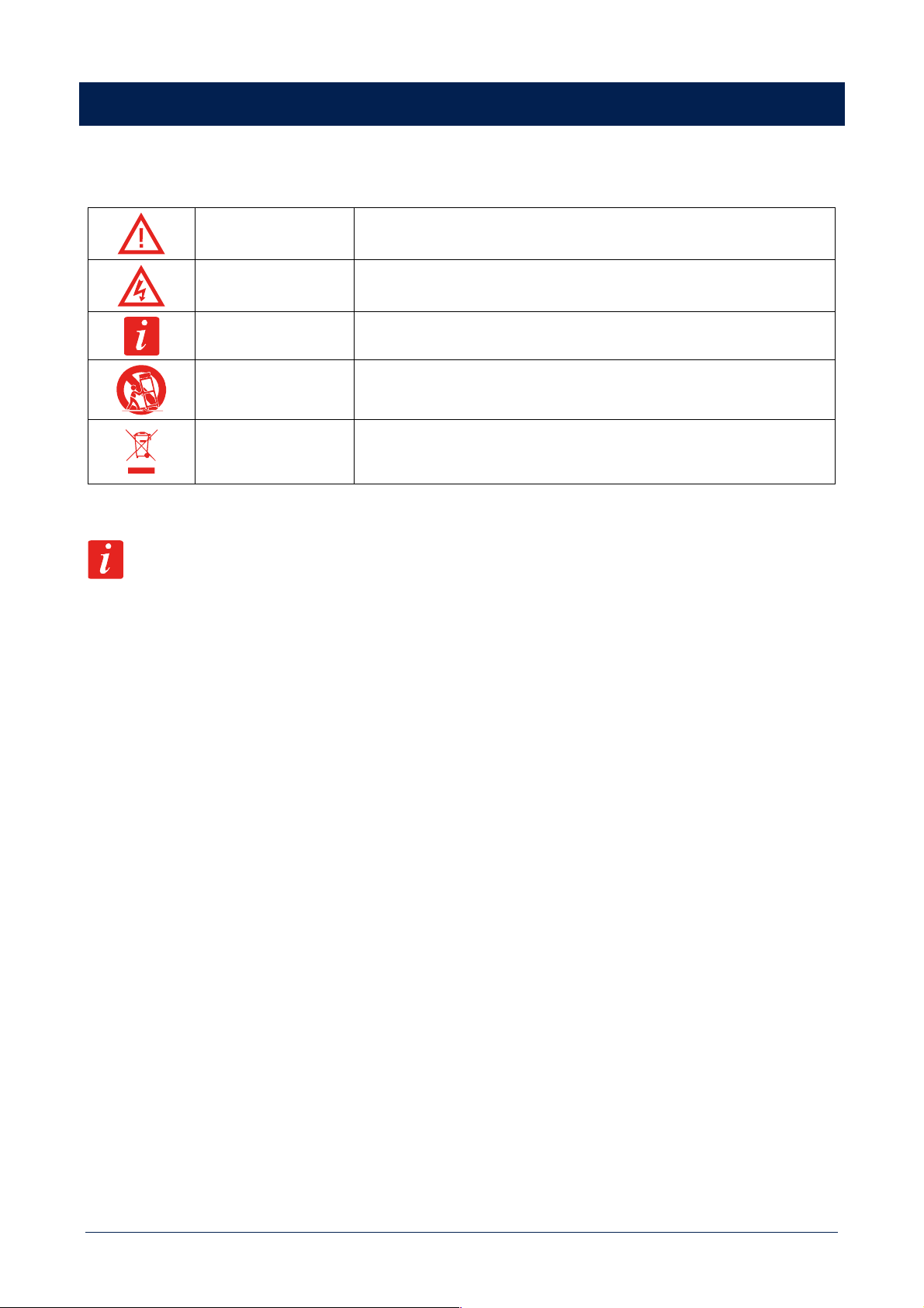
Symbols used in this document give notice of important operating instructions and warnings which must be strictly followed.
CAUTION
Important operating instructions: explains hazards that could damage a product,
including data loss
WARNING
Important advice concerning the use of dangerous voltages and the potential
risk of electric shock, personal injury or death.
IMPORTANT NOTES
Helpful and relevant information about the topic
SUPPORTS, TROLLEYS
AND CARTS
Information about the use of supports, trolleys and carts. Reminds to move with
extreme caution and never tilt.
WASTE DISPOSAL
This symbol indicates that this product should not be disposed with your
household waste, according to the WEEE directive (2012/19/EU) and your
national law.
IMPORTANT NOTES
This manual contains important information about the correct and safe use of the device. Before connecting and using this product,
please read this instruction manual carefully and keep it on hand for future reference. The manual is to be considered an integral part
of this product and must accompany it when it changes ownership as a reference for correct installation and use as well as for the
safety precautions. RCF S.p.A. will not assume any responsibility for the incorrect installation and / or use of this product.
SAFETY PRECAUTIONS
1. All the precautions, in particular the safety ones, must be read with special attention, as they provide important information.
2. Power supply from mains
a. The mains voltage is sufficiently high to involve a risk of electrocution; install and connect this product before plugging it in.
b. Before powering up, make sure that all the connections have been made correctly and the voltage of your mains corresponds to
the voltage shown on the rating plate on the unit, if not, please contact your RCF dealer.
c. The metallic parts of the unit are earthed through the power cable. An apparatus with CLASS I construction shall be connected to
a mains socket outlet with a protective earthing connection.
d. Protect the power cable from damage; make sure it is positioned in a way that it cannot be stepped on or crushed by objects.
e. To prevent the risk of electric shock, never open this product: there are no parts inside that the user needs to access.
f. Be careful: in the case of a product supplied by manufacturer only with POWERCON connectors and without a power cord, jointly
to POWERCON connectors type NAC3FCA (power-in) and NAC3FCB (power-out), the following power cords compliant to national
standard shall be used:
- EU: cord type H05VV-F 3G 3x2.5 mm2 - Standard IEC 60227-1
- JP: cord type VCTF 3x2 mm2; 15Amp/120V~ - Standard JIS C3306
- US: cord type SJT/SJTO 3x14 AWG; 15Amp/125V~ - Standard ANSI/UL 62
3. Make sure that no objects or liquids can get into this product, as this may cause a short circuit. This apparatus shall not be exposed
to dripping or splashing. No objects filled with liquid, such as vases, shall be placed on this apparatus. No naked sources (such as
lighted candles) should be placed on this apparatus.
4. Never attempt to carry out any operations, modifications or repairs that are not expressly described in this manual. Contact your
authorized service centre or qualified personnel should any of the following occur:
- The product does not function (or functions in an anomalous way).
- The power cable has been damaged.
6
- Objects or liquids have got in the unit.
- The product has been subject to a heavy impact.
5. If this product is not used for a long period, disconnect the power cable.
6. If this product begins emitting any strange odours or smoke, switch it off immediately and disconnect the power cable.
7. Do not connect this product to any equipment or accessories not foreseen.
For suspended installation, only use the dedicated anchoring points and do not try to hang this product by using elements that are
unsuitable or not specific for this purpose. Also check the suitability of the support surface to which the product is anchored (wall,
ceiling, structure, etc.), and the components used for attachment (screw anchors, screws, brackets not supplied by RCF etc.), which
must guarantee the security of the system / installation over time, also considering, for example, the mechanical vibrations normally
generated by transducers. To prevent the risk of falling equipment, do not stack multiple units of this product unless this possibility is
specified in the user manual.
8. RCF S.p.A. strongly recommends this product is only installed by professional qualified installers (or specialised
firms) who can ensure correct installation and certify it according to the regulations in force. The entire audio
system must comply with the current standards and regulations regarding electrical systems.
9. Supports, trolleys and carts.
The equipment should be only used on supports, trolleys and carts, where necessary, that are recommended by the
manufacturer. The equipment / support / trolley / cart assembly must be moved with extreme caution. Sudden stops, excessive
pushing force and uneven floors may cause the assembly to overturn. Never tilt the assembly.
10. There are numerous mechanical and electrical factors to be considered when installing a professional audio system (in addition to
those which are strictly acoustic, such as sound pressure, angles of coverage, frequency response, etc.).
11. Hearing loss. Exposure to high sound levels can cause permanent hearing loss. The acoustic pressure level that leads to hearing
loss is different from person to person and depends on the duration of exposure. To prevent potentially dangerous exposure to
high levels of acoustic pressure, anyone who is exposed to these levels should use adequate protection devices. When a transducer
capable of producing high sound levels is being used, it is therefore necessary to wear ear plugs or protective earphones. See the
manual technical specifications to know the maximum sound pressure level.
OPERATING PRECAUTIONS
- Place this product far from any heat sources and always ensure an adequate air circulation around it.
- Do not overload this product for a long time.
- Never force the control elements (keys, knobs, etc.).
- Do not use solvents, alcohol, benzene or other volatile substances for cleaning the external parts of this product.
IMPORTANT NOTES
To prevent the occurrence of noise on line signal cables, use screened cables only and avoid putting them close to:
- Equipment that produces high-intensity electromagnetic fields
- Power cables
- Loudspeaker lines
WARNING! CAUTION! To prevent the risk of fire or electric shock, never expose this product to
rain or humidity.
WARNING! To prevent electric shock hazard, do not connect to mains power supply while grille is
removed.
7
WARNING! to reduce the risk of electric shock, do not disassemble this product unless you are qualified.
Refer servicing to qualified service personnel.
CORRECT DISPOSAL OF THIS PRODUCT
This product should be handed over to an authorized collection site for recycling waste electrical and electronic equipment (EEE).
Improper handling of this type of waste could have a possible negative impact on the environment and human health due to potentially
hazardous substances that are generally associated with EEE. At the same time, your cooperation in the correct disposal of this product
will contribute to the effective usage of natural resources. For more information about where you can drop off your waste equipment
for recycling, please contact your local city office, waste authority or your household waste disposal service.
CARE AND MAINTENANCE
To ensure a long-life service, this product should be used following these advices:
- If the product is intended to be set up outdoors, be sure it is under cover and protected to rain and moisture.
- If the product needs to be used in a cold environment, slowly warm up the voice coils by sending a low-level signal for about 15
minutes before sending high-power signals.
- Always use a dry cloth to clean the exterior surfaces of the speaker and always do it when the power is turned off.
CAUTION: to avoid damaging the exterior finishes do not use cleaning solvents or abrasives.
WARNING! CAUTION! For powered speakers, do cleaning only when the power is turned off.
FCC NOTES
This equipment has been tested and found to comply with the limits for a Class A digital device, pursuant to Part 15 of the FCC Rules.
These limits are designed to provide reasonable protection against harmful interference when the equipment is operated in a
commercial environment. This equipment generates, uses, and can radiate radio frequency energy, and if it is not installed and used
in accordance with the instruction manual, it may cause harmful interference to radio communications. Operation of this equipment
in a residential area is likely to cause harmful interference, in which case the user will be required to correct the interference at his
own expense.
Modifications: Any modifications made to this device that are not approved by RCF may void the authority granted to the user by
the FCC to operate this equipment.

8
RCF S.p.A. thanks you for purchasing this product, which has been designed to guarantee reliability and high
performance.
INTRODUCTION ABOUT THE BUSINESS MUSIC LINE
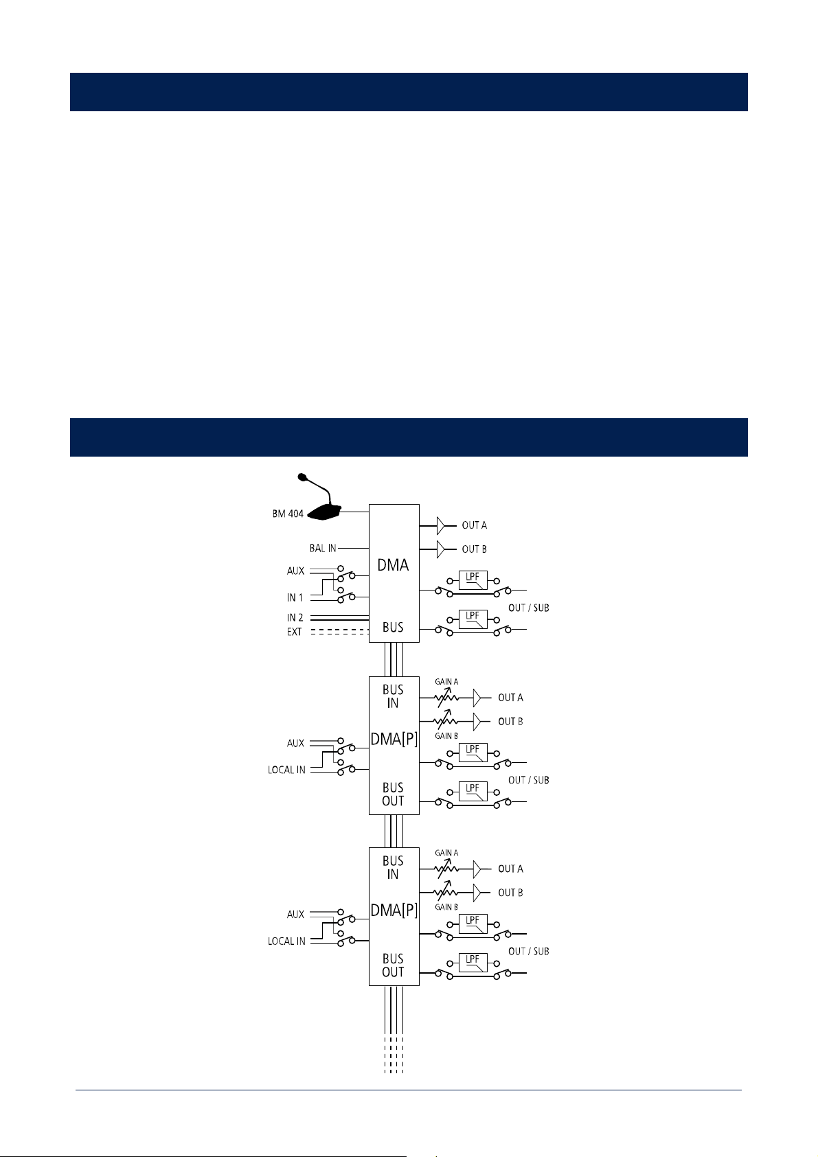
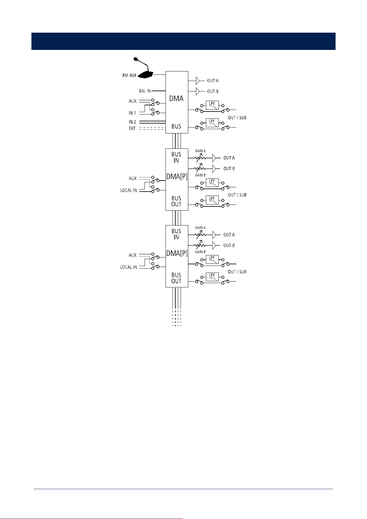
BUSINESS MUSIC line includes DMA 82 / DMA 162 digital matrix amplifiers, DMA 162P (also called DMA[P] in the following) digital
power amplifier, BM 404 paging microphone, remote controls and speakers, offering a complete sound system and maximizing the
overall acoustic performance. DMA / DMA[P] amplifiers are extremely compact (1/2 19” rack unit wide and 1 unit high) that make
them ideal for either desktop or rack installation (with optional accessories) and are suitable for a wide range of system solutions,
from retail stores to bars and restaurants, meeting rooms, education or public facilities and any A/V application. Their accurate design
together with environmental robustness (IP 30 protection grade and high efficiency thermal dissipation) represents a junction point
between professional and consumer markets.
This line includes both ceiling and wall mount speakers, which have professional acoustic performances and a high valued industrial
design, it has different configuration levels, from the user friendly front control panel to the RCF ‘RDNet’ for large and complex systems,
with a highly scalable architecture. Control units can send up to four mono / two stereo audio channels to satellite units through a
single CAT5 cable. This allows to increase the installed power and create a multi-room architecture as well, with a simple connection
among devices.
DMA 82 / DMA 162 DESCRIPTION AND MAIN FEATURES
DMA 82 and DMA 162 are two-channel class-D matrix amplifiers, both equipped with a powerful DSP platform, allowing managing
inputs and outputs in terms of routing and equalization (a complete set of processing functions is available, including PEQ, FIR filters,
bass enhancement, limiters, compressors and environmental equalization); moreover, dedicated presets for RCF speakers have been
implemented to optimize their acoustic performance. The two models only differ in the output power:
- DMA 82 either 2 ch. x 80 W RMS @ 4 Ω or a single 160 W 70 V line
- DMA 162 either 2 ch. x 160 W RMS @ 4 Ω or a single 320 W 70 V line.
Each DMA is suitable for either desktop or rack installation (thanks to its dedicated optional accessory). Each unit has 2 stereo LINE
audio inputs on RCA connectors, 1 MIC+LINE balanced audio input on removable screw terminals and a LINE audio output with a
switchable low-pass filter useful for the connection to an active subwoofer. A dedicated input having RJ 45 connector allows the
connection of up to four BM 404 paging microphones (interlocked one another on a single chain). A RC 401 wall-mount remote
control can be linked to each output channel in order to adjust its respective volume level and select the desired audio input. DMA
can send up to 4 audio channels to satellite DMA[P] units (through a BUS with a single CAT5 cable), combining a flexible and scalable
multi-room architecture with an easy connection and installation. Its configuration is user friendly and can be carried out through
either its front panel controls (with OLED display) or RDNet (when its optional board is installed).
DMA 162P DESCRIPTION AND MAIN FEATURES
DMA 162P is a two-channel class-D power amplifier. Output power: either 2 channels x 160 W RMS @ 4 Ω - or a single 320 W 70 V
line. Up to 4 DMA [P] can be linked to a single DMA unit in order to increase the system output power and implement multi-room
architectures. However, each DMA[P] can be used as a stand alone amplifier as well. Each amplifier is suitable for either desktop or
rack installation (thanks to its dedicated optional accessory). DMA[P] can receive processed audio signals from a DMA amplifier on a
four-channel audio BUS (either four mono or one stereo and two mono or two stereo, the four signals are the same sent to the DMA
power amplifiers), or as alternative, it is possible to select the local stereo LINE input (by closing the dedicated contact). A LINE output
is also available, with a switchable low-pass filter for the connection to an active subwoofer. Its configuration can be carried out
though either the dip-switches on its rear panel or RDNet (when its optional board is installed).
9
UNPACKING, INSTALLATION AND COOLING
Check the carton box and its contents and if there is any sign of damage (should the amplifier be damaged, immediately inform your
local distributor / dealer and the forwarder). It is always advisable to keep the packing materials, even if the amplifier has arrived in
good condition. The power cord is included. DMA / DMA[P] amplifiers can be installed into a 19” rack cabinet (an optional accessory
is required for every pair, as each amplifier needs half a rack unit). Amplifiers should not be installed in a place with:
- Too high temperature, dust or excessive humidity.
- Exhaust air ventilators.
- Permanent vibrations.
- High-intensity electromagnetic fields (due to transformers, transmitters, etc.).
Make sure there is an adequate ventilation and amplifiers sides have enough room. The temperature inside the rack cabinet should
be kept below 35°C (95°F). For safety reasons, never disconnect the earth (ground) pin of the mains power cord. Use audio shielded
cables to avoid hum and interference.
AUDIO BLOCK DIAGRAM

10
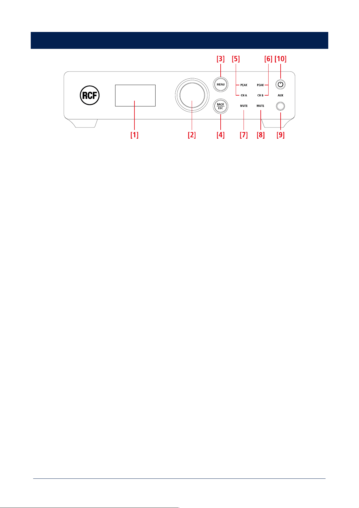
DMA 82 / DMA 162 FRONT PANEL
[1] Display (OLED). When no menu is selected, the current output levels are displayed as bars.
[2] Rotary encoder and push-button to select. Turn the encoder either clockwise to increase the MASTER VOLUME level or
counterclockwise to decrease it. Press it to toggle MUTE ALL / UNMUTE ALL. In the edit mode (after pressing MENU [3]): turn the
encoder either clockwise to scroll the menu downwards or increase the selected parameter value, turn it counterclockwise to scroll
the menu upwards or decrease the selected parameter value. Press to select (and enter a submenu).
[3] MENU button: press to enter the edit mode and select the menu home page.
[4] BACK / ESC button: press to quit the displayed menu. If pressed for 4 seconds, it activates the “lock” state of the front panel and
inhibit all commands. A small locker icon in the upper-left corner of the display will be shown. To release the function press again for
4 seconds.
[5] CH A / PEAK (two LEDs): CH A is lit when the audio signal is present on the channel A. PEAK blinks when the signal level of the
channel A reaches the clipping point, causing the limiter intervention; if it is steady lit, its volume level is excessive and needs to be
reduced.
[6] CH B / PEAK (two LEDs): CH B is lit when the audio signal is present on the channel B. PEAK blinks when the signal level of the
channel B reaches the clipping point, causing the limiter intervention; if it is steady lit, its volume level is excessive and needs to be
reduced.
[7] CHANNEL A MUTE (LED): when lit, the channel A output is muted.
[8] CHANNEL B MUTE (LED): when lit, the channel B output is muted.
[9] AUX input (3.5 mm stereo TRS jack). If a jack plug is inserted into this input, the rear panel INPUT 1 is disabled.
[10] STAND-BY button with LED: push to toggle the amplifier on/stand-by. The LED is lit white when the amplifier is turned on, red
when the amplifier is in stand-by.
11
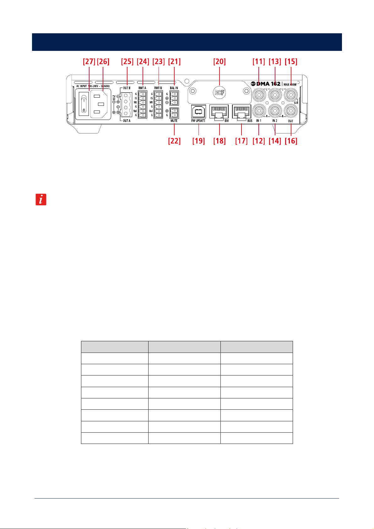
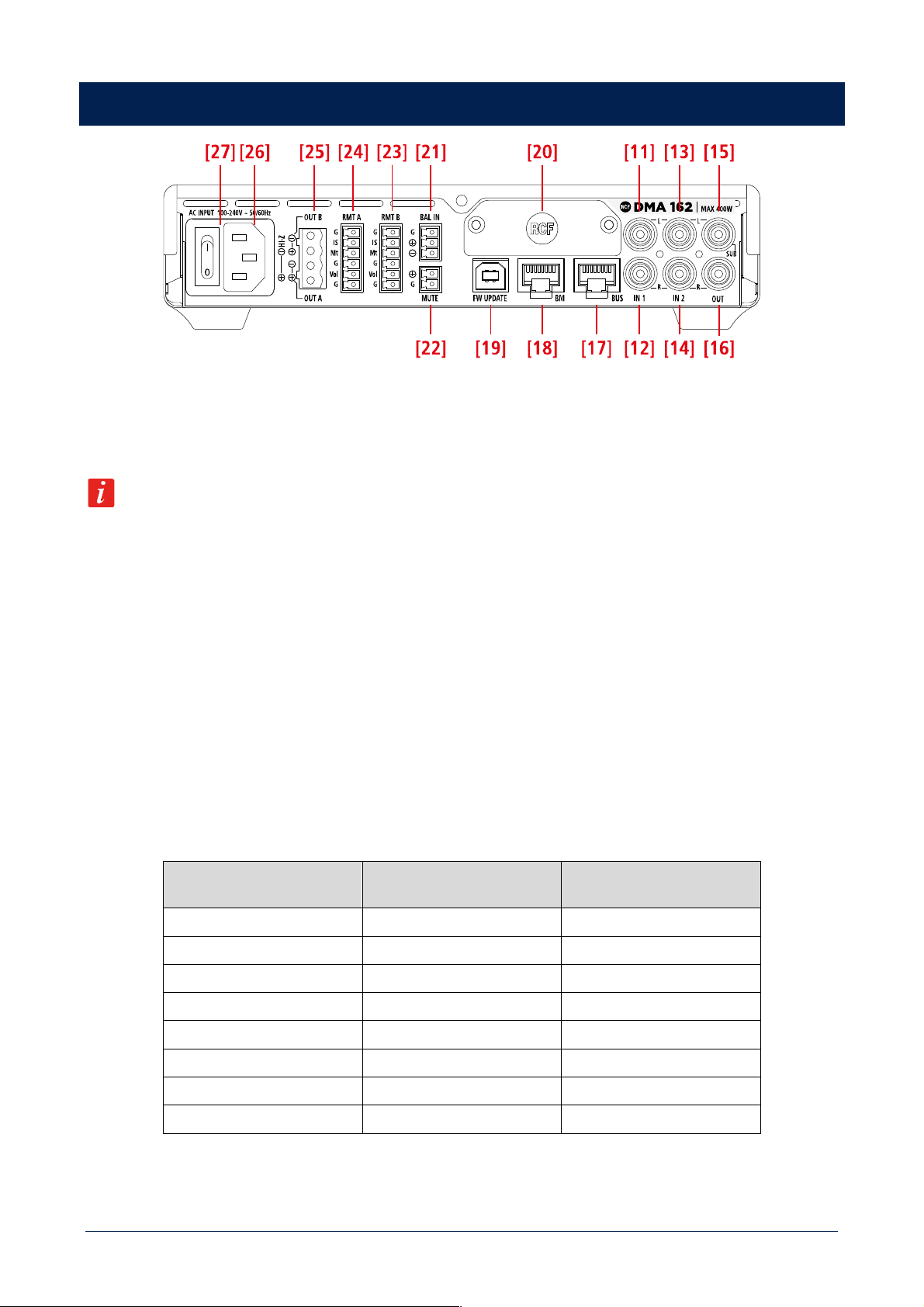
DMA 82 / DMA 162 REAR PANEL
[11] AUDIO INPUT 1 (left channel): unbalanced line level input with RCA socket.
[12] AUDIO INPUT 1 (right channel): unbalanced line level input with RCA socket.
If a jack plug is inserted into the front panel AUX input [9], the rear panel audio INPUT 1 [11], [12] is momentary disabled.
[13] AUDIO INPUT 2 (left channel): unbalanced line level input with RCA socket.
[14] AUDIO INPUT 2 (right channel): unbalanced line level input with RCA socket.
[15 AUDIO OUTPUT (left channel) / SUB OUT: unbalanced line level output with RCA socket. It can be set to send either a copy of
the output A audio signal (BUS 1; left channel if stereo) or the same signal filtered by a low-pass filter (80 Hz) useful for connecting
an active subwoofer.
[16] AUDIO OUTPUT (right channel) / SUB OUT: unbalanced line level output with RCA socket. It can be set to send either a copy
of the output B audio signal (BUS 2; right channel if stereo) or the same signal filtered by a low-pass filter (80 Hz) useful for connecting
an active subwoofer.
[17] BUS output (RJ45 socket): it needs to be linked to the BUS input of the first DMA[P] amplifier (if present).
PIN BUS AUDIO OUTPUT WIRE COLOUR (T568B)
1 1 - white --- orange
2 1 + orange
3 2 - white --- green
4 3 - blue
5 3 + white --- blue
6 2 + green
7 4 - white --- brown
8 4 + brown
12
[18] BM: input (RJ45 socket) for BM 404 paging microphones. Up to four BM 404 paging microphones can be linked in ‘daisy-chain’.
PIN DESCRIPTION WIRE COLOUR (T568B)
1 PAGING AUDIO SIGNAL - white --- orange
2 PAGING AUDIO SIGNAL + orange
3 ground white --- green
4 PAGING ENABLE SIGNAL blue
5 ZONE A SELECTION white --- blue
6 ZONE B SELECTION green
7 ZONE C SELECTION white --- brown
8 ZONE D SELECTION brown
As alternative (when no BM 404 microphones are connected), BM input can also be used as additional auxiliary input by connecting
the first three pins only.
[19] FW UPDATE: USB (type B) port to link a computer (PC) locally. This port can be used either to control the amplifier through the
RDNET software or update its firmware.
[20] Blank panel to be removed when installing the optional RDNET board.
[21] BALANCED AUDIO INPUT for a removable screw terminal block. This input has the VOX function: a signal detection that gives
automatic priority.
G ground
+ audio signal + (hot)
- audio signal – (cold)
[22] MUTE: (removable screw terminal block): remote mute command (a dry closing contact) active when its contacts are shorted.
[23] RMT B and [24] RMT A: input (removable screw terminal block) for optional RC 401 remote controls. Refer to the specific
section for functioning instructions. RC 401 pin out is shown in the table below.
G Ground
Is Input Selection
Mt Mute
G Ground
Vol Volume
G Ground
13
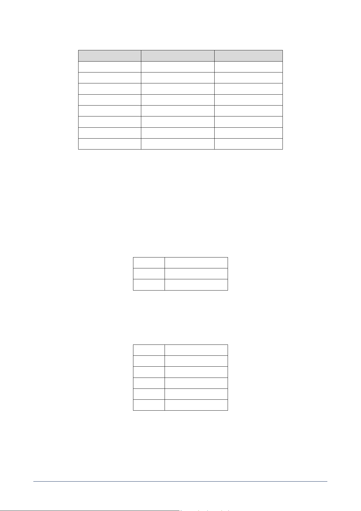
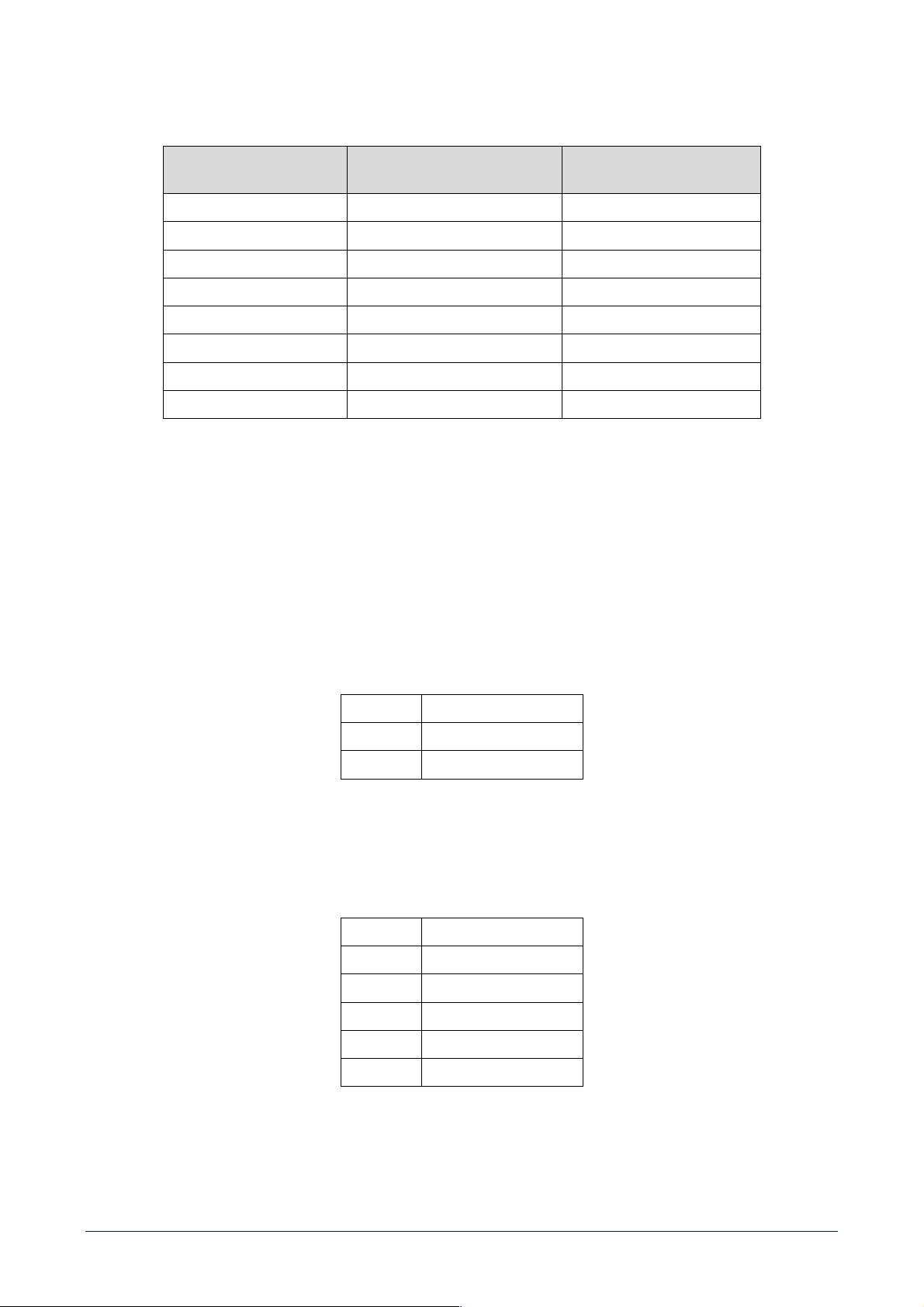
[25] SPEAKER OUTPUTS
DMA amplifier speaker outputs allow either two channels for a low-impedance connection or a single 70 V line for speakers having
matching transformers.
Connector: EUROBLOCK (removable screw terminal block).
TWO CHANNELS (A, B) --- LOW IMPEDANCE CONNECTION (4 Ω)
Connect speakers as shown in the figure.
Minimum load impedance is 4 Ω per speaker output.
DELIVERED POWER
DMA 82: 2 x 80 W RMS @ 4 Ω
DMA 162: 2 x 160 W RMS @ 4 Ω
An impedance equal to 4 Ω allows to get the max. power (80 / 160 W).
A higher impedance leads to a reduction of the delivered power (e.g. 8 Ω: ca. 40
/ 80 W), an impedance lower than 4 Ω overloads the amplifier.
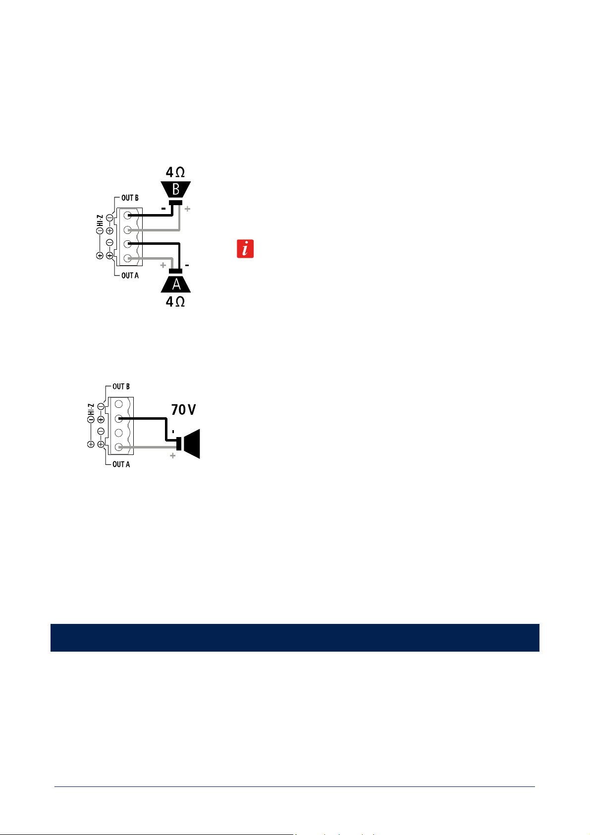
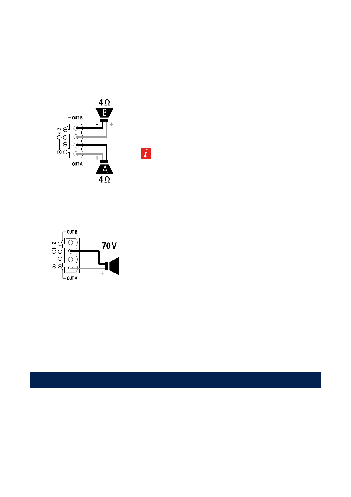
BRIDGE MODE OR HI IMPEDANCE 70 V
Connect speakers as shown in the figure.
BRIDGE MODE
Channels A, B are bridged by setting the BRIDGE MODE to ON (see the
next manual sections ‘DMA 82 / DMA 162 operation modes’ and ‘DMA 82 / DMA
162 settings’) and can work both at low impedance speakers and hi impedance
(70 V).
Do NOT connect the other two contacts.
The overall speaker power shall not exceed 160 W (DMA 82) / 320 W (DMA 162).
[26] Power cord input.
Connect the power cord only to a mains socket outlet with a protective earthing connection.
[27] Power switch: push to turn on (I) / off (O) the amplifier.
DMA 82 / DMA 162 OPERATION MODES
After inserting the correct password (menu: SETTING > PASSWORD), it is possible to set the DMA operation among the three different
modes: mono, stereo, bridge. To activate the stereo mode, in the menu select the STEREO MODE parameter and turn it on. To activate
the bridge mode (single 70 V line output), in the menu select the BRIDGE MODE parameter and turn it on. The two parameters STEREO
MODE and BRIDGE MODE are mutually exclusive, when turning one on, the other automatically turns off. For the MONO mode, leave
both parameters set to OFF.
14
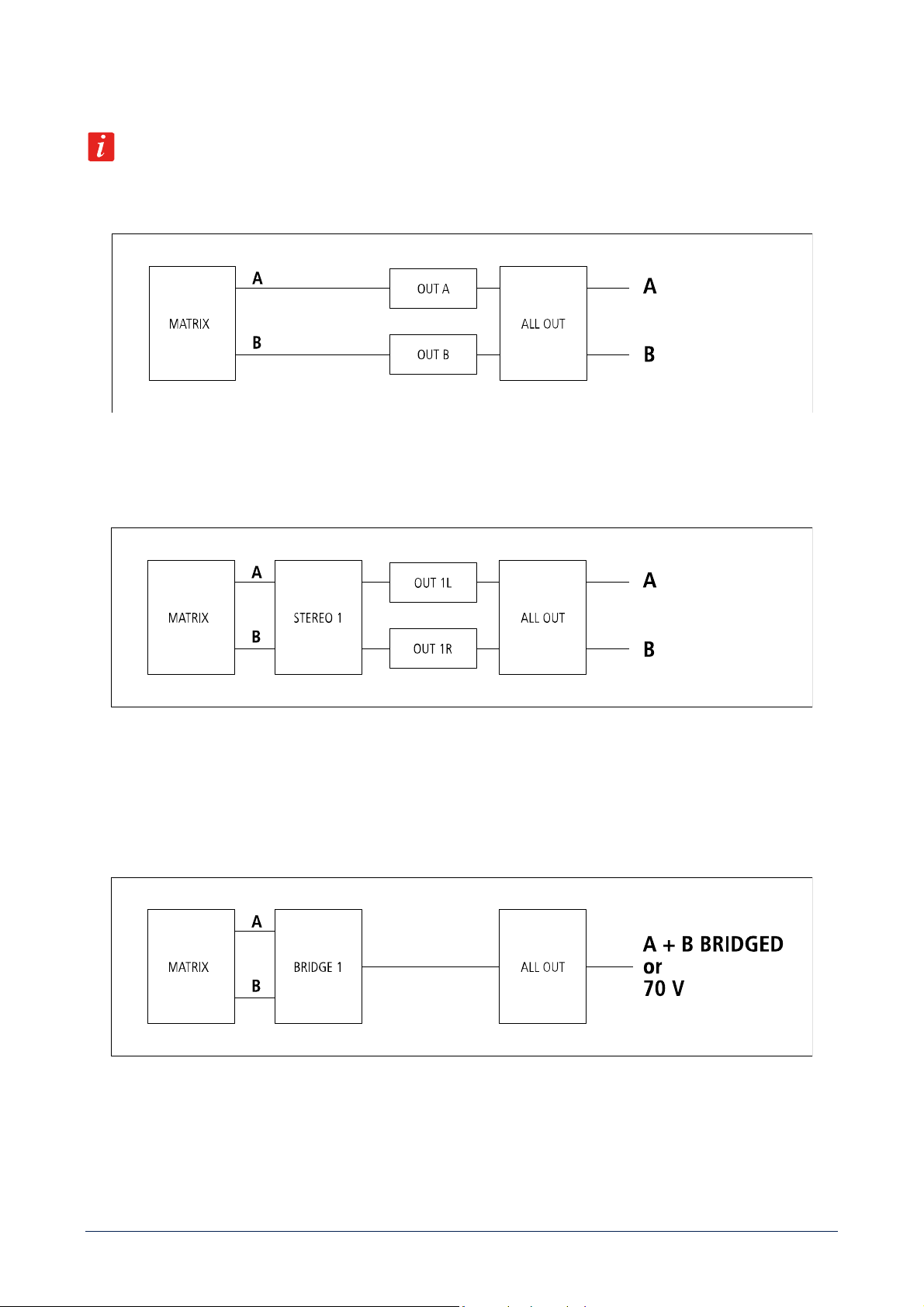
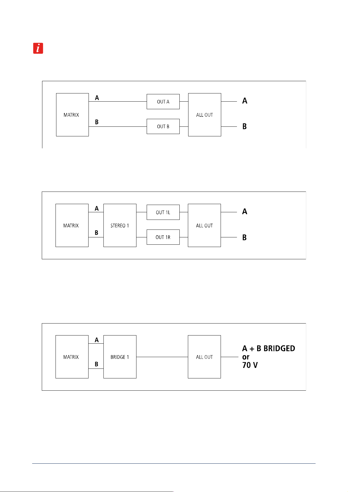
OUTPUT VOLUME CONTROL BLOCK DIAGRAMS
Note: ALL OUT is always the master volume.
MONO
The two outputs A and B are independent and have separate volume controls: OUT A and OUT B.
STEREO
The DMA can manage stereo inputs.
STEREO1 is the common volume for both left (A) and right (B) channels.
OUT 1L and the OUT 1R are the single channel volume controls (useful for balance).
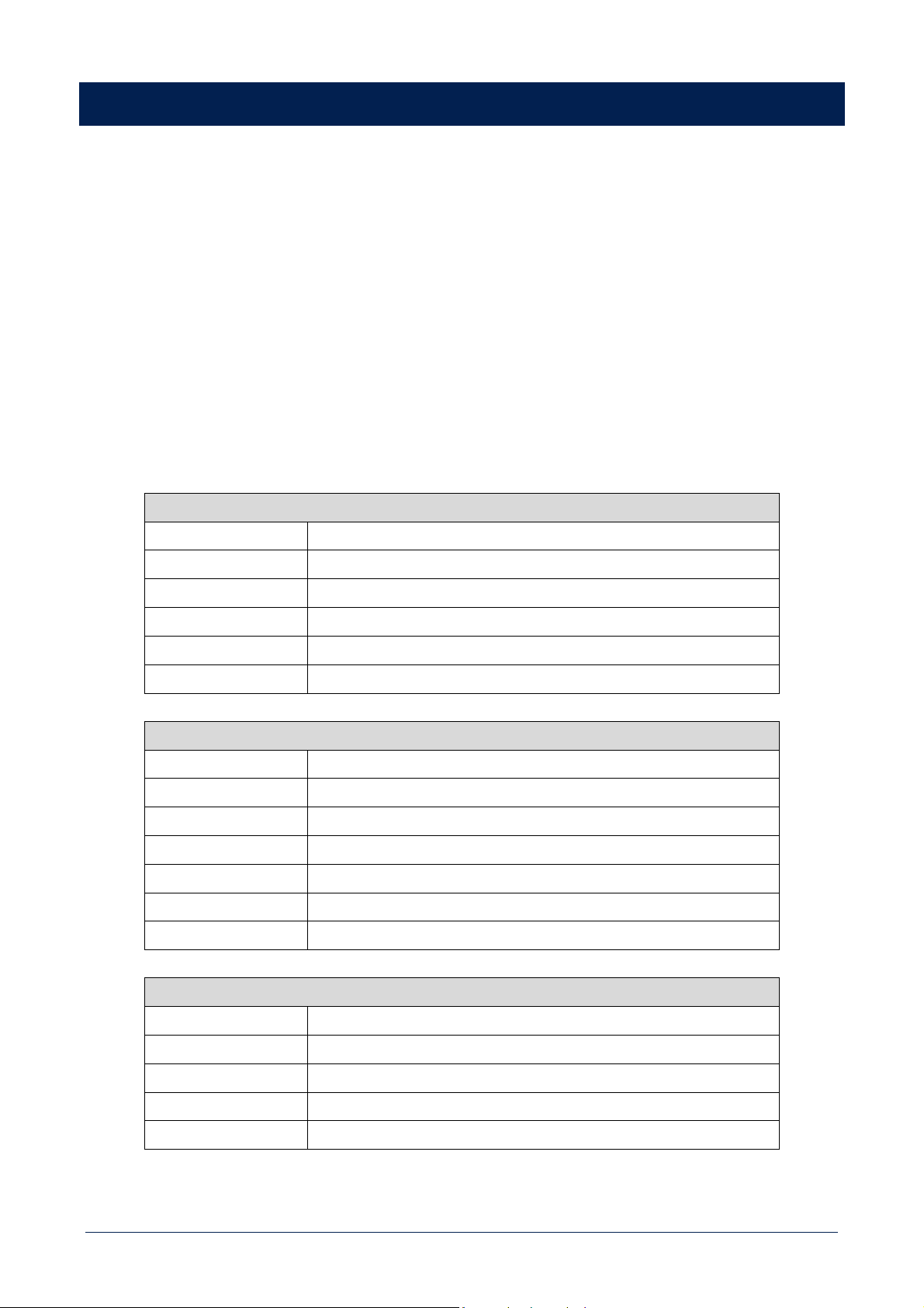
BRIDGE
The two outputs are bridged or can get a single 70 V line (mono).
BRIDGE1 is the common volume control.
15
DMA 82 / DMA 162 SETTINGS
Press the front panel MENU button [3] to enter the edit mode and select the menu home page.
Turn the rotary encoder [2] either clockwise to scroll the menu downwards or increase the selected parameter value, turn it
counterclockwise to scroll the menu upwards or decrease the selected parameter value.
Press the rotary encoder [2] to select (and enter a submenu).
Press the BACK / ESC button [4] to quit the displayed menu.
All parameters highlighted in grey are available only after entering (in the setting menu) the proper password / 4-digit code: 7471.
All audio inputs highlighted in grey are available after setting the ADVANCED MODE parameter (in the setting menu) to ON.
NOTES:
- When in STEREO mode, all stereo inputs (IN 1, IN 2, EXT) are routed in stereo to main outputs A, B and OUT / SUB.
- BAL IN and BM inputs are always routed in mono to all outputs.
- In the advanced mode, separate mono inputs such as IN 1L, IN 1R, IN 2L, IN 2R, EXT L and EXT R, when routed to a stereo
output, are sent to the respective channel only (left for inputs labelled L, right for inputs labelled R) and muted to the other
channel.
HOME PAGE (when in mono mode)
OUT A
Enter the OUT menu for OUT A only
OUT B
Enter the OUT menu for OUT B only
ALL OUT
Enter the ALL OUT menu
INPUT
Enter the INPUT menu
BUS OUT
Enter the BUS OUT menu
SETTING
Enter the SETTING menu
HOME PAGE (when in stereo mode)
STEREO1
Enter the STEREO1 menu
OUT 1L
Enter the OUT menu for the left channel (OUT A) only
OUT 1R
Enter the OUT menu for the right channel (OUT B) only
ALL OUT
Enter the ALL OUT menu
INPUT
Enter the INPUT menu
BUS OUT
Enter the BUS OUT menu
SETTING
Enter the SETTING menu
HOME PAGE (when in bridge mode, 70 V out)
BRIDGE1
Enter the BRIDGE1 menu
ALL OUT
Enter the ALL OUT menu
INPUT
Enter the INPUT menu
BUS OUT
Enter the BUS OUT menu
SETTING
Enter the SETTING menu
16
OUT MENU
VOLUME Adjusts the selected output volume level
MUTE Mutes (ON) or unmutes (OFF) the selected output
INPUT SELECTION
Selects the audio input among: IN 1, IN 2, EXT (input reserved for optional
boards), BAL IN, BM (when used as aux input), IN 1L, IN 1R, IN 2L, IN 2R, EXT
L, EXT R
STEREO MODE Turns ON / OFF the STEREO mode
BRIDGE MODE Turns ON / OFF the BRIDGE mode
SPEAKER PRESET Selects the speaker preset (suitable for the used model)
HP FILTER Selects the high-pass filter cutoff frequency of the selected output
BASS ENHANCER Turns ON / OFF the bass enhancer
PEQ Enter to a submenu including two parametric equalizers (PEQ). Select a PEQ and
edit the GAIN, the FREQUENCY and Q factor
POLARITY Inverts (when ON) the signal polarity
STEREO1 MENU (when in stereo mode)
VOLUME Adjusts the output volume level of both outputs
MUTE Mutes (ON) or unmutes (OFF) both outputs
INPUT SELECTION
Selects the audio input among: IN 1, IN 2, EXT (input reserved for optional
boards), BAL IN, BM (when used as aux input), IN 1L, IN 1R, IN 2L, IN 2R, EXT
L, EXT R
STEREO MODE Turns ON / OFF the STEREO mode
BRIDGE MODE Turns ON / OFF the BRIDGE mode
BRIDGE1 MENU (when in bridge mode)
VOLUME Adjusts the output volume level
MUTE Mutes (ON) or unmutes (OFF) the output (both channels)
INPUT SELECTION Selects the audio input among: IN 1, IN 2, EXT (input reserved for optional
boards), BAL IN, BM (when used as aux input), IN 1L, IN 1R, IN 2L, IN 2R, EXT
L, EXT R
STEREO MODE Turns ON / OFF the STEREO mode
BRIDGE MODE Turns ON / OFF the BRIDGE mode
SPEAKER PRESET Selects the speaker preset (suitable for the used model)
HP FILTER Selects the high-pass filter cutoff frequency of the selected output
BASS ENHANCER Turns ON / OFF the bass enhancer
PEQ
Enter to a submenu including two parametric equalizers (PEQ). Select a PEQ and
edit the GAIN, the FREQUENCY and Q factor
POLARITY Inverts (when ON) the signal polarity
17
ALL OUT MENU
VOLUME Adjusts the output volume level of all outputs
MUTE Mutes (ON) or unmutes (OFF) all outputs
INPUT SELECTION
Selects the audio input among: IN 1, IN 2, EXT (input reserved for optional
boards), BAL IN, BM (when used as aux input), IN 1L, IN 1R, IN 2L, IN 2R, EXT
L, EXT R
INPUT MENU
After entering the INPUT menu, select an audio input among IN 1, IN 2, EXT (input reserved for optional
boards), BAL IN, BM, IN 1L, IN 1R, IN 2L, IN 2R, EXT L or EXT R to edit its parameters:
VOLUME Adjusts the level of the selected input
3B EQ 3-band equalizer: allows to adjust LOW, MID and HIGH frequencies
After choosing BAL IN, three additional parameters are available:
LINE/MIC LEVEL Sets the BAL IN level either as LINE or MIC
VOX Toggles ON / OFF the VOX function (automatic priority when a signal
is detected at the BAL IN) and sets the threshold LEVEL
POLARITY Inverts (when ON) the signal polarity
BUS OUT MENU
After entering the BUS OUT menu (relevant to the BUS output), select either a CHANNEL (1, 2, 3, 4) or SUB
/AUX. After selecting a channel, a submenu appears:
VOLUME Adjusts the level of the selected channel
FLAT EQ Toggles the FLAT EQ ON / OFF on the selected channel.
‘Flat Eq.’: no equalization
INPUT SELECTION Selects the audio input among: IN 1, IN 2, EXT (input reserved for optional
boards), BAL IN, BM (when used as aux input), IN 1L, IN 1R, IN 2L, IN 2R, EXT
L, EXT R. Available only for CHANNEL 3 and CHANNEL 4
After selecting SUB / AUX, it is possible to toggle ON/OFF the SUB function of the rear panel.
OUT / SUB [15], [16]. If set to ON, those outputs are affected by a 80 Hz low-pass filter for connecting
active subwoofers.
SETTING MENU
PASSWORD
Allows to enter the 4-digit code (7471) to access all parameters
INFO Shows information related to firmware versions and amplifier temperature.
OUTPUT LABEL Allows to give new labels to OUT A and OUT B in the menus
FACTORY RESET Allows to restore the factory settings
LANGUAGE Menu language selection
ADVANCED MODE If set to OFF (default), inputs IN 1, IN 2 and EXT are fixed as stereo pairs, if set
to ON, additional input options are available
18
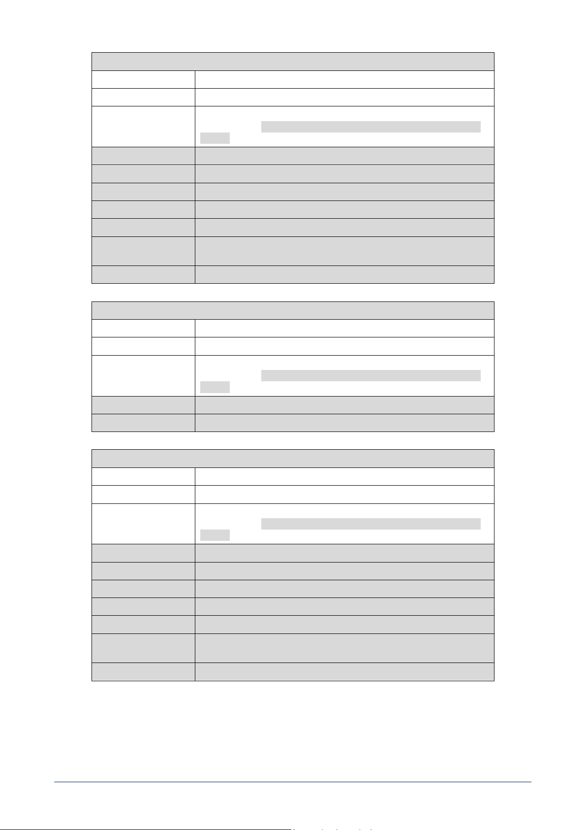
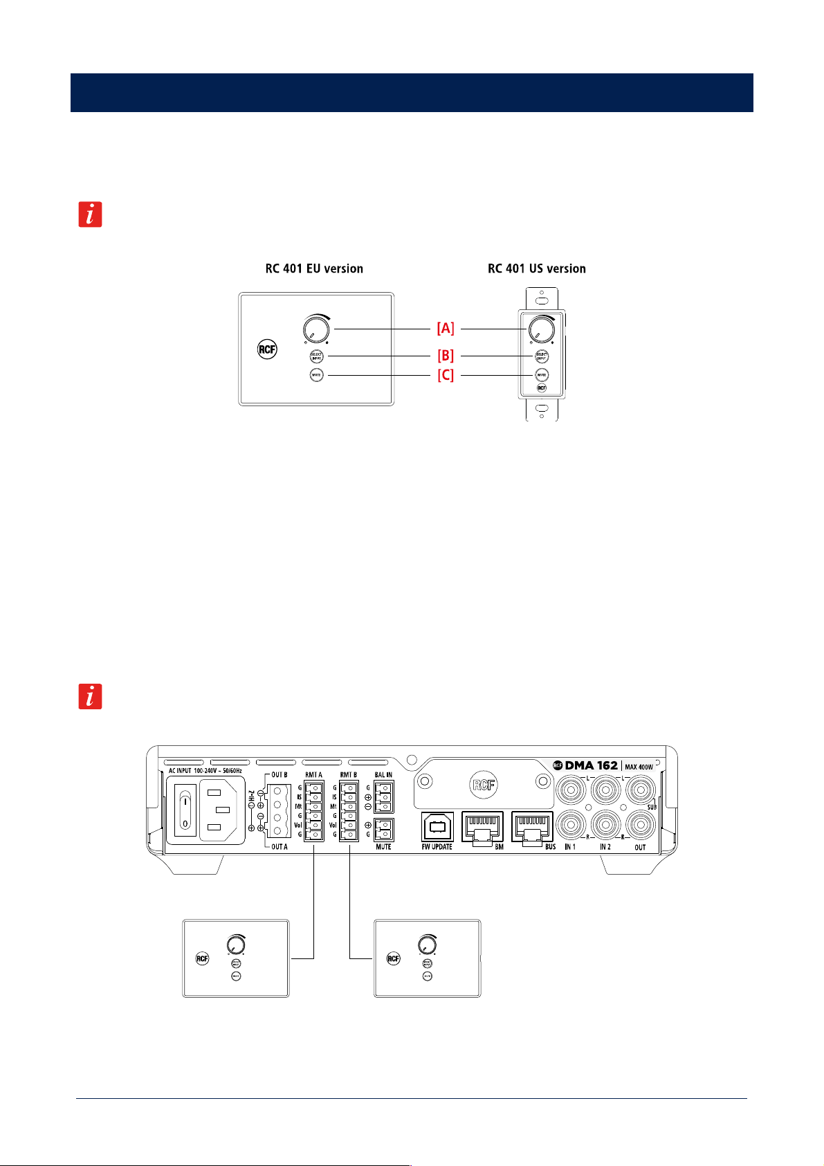
RC 401 REMOTE CONTROLS
RC 401 is a wall mount remote that works in combination with DMA units. It can be connected to each DMA power output and allows
adjusting the output volumes, muting them or selecting the desired input program.
When RC 401 is connected to a DMA unit, it is the only outputs volumes control, are the corresponding controls
in the DMA menu will be disabled.
RC 401 provides the following functions:
[A] OUTPUT VOLUME CONTROL. The knob adjusts the output volume in the range -36 dB ÷ +12 dB.
[B] SELECT INPUT. Allows to loop DMA unit inputs, with sequence IN 1 > IN 2 > BAL IN.
[C] MUTE. Mutes the DMA unit output volume.
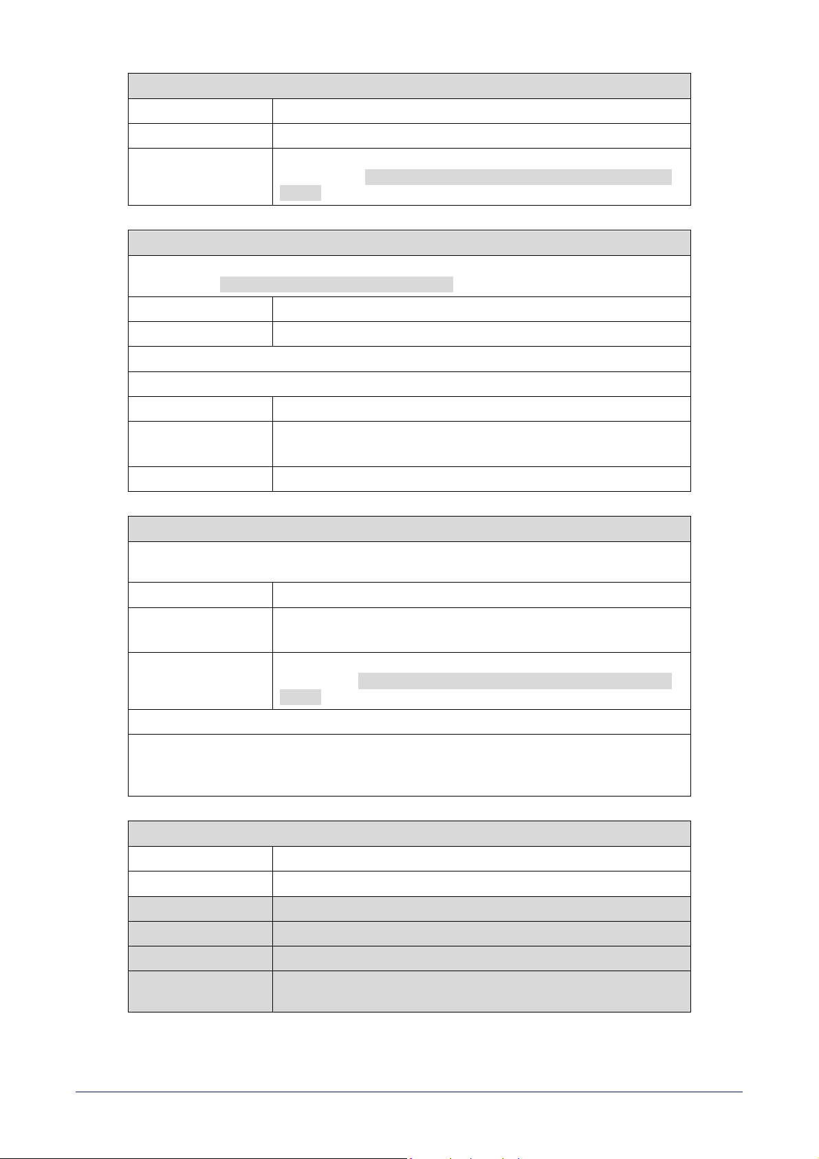
RC 401 shall be connected on the rear panel of DMA units, with the dedicated removable screw terminal connectors.
- It is possible to connect one RC 401 to each DMA unit power output.
- The maximum distance between DMA unit and RC 401 is 50m.
- Connection shall be done with CAT5 shielded cable.
Wiring schemes shown in Figure 1 and Figure 2 represent the configuration to implement the applications
described in the following tables.
Figure 1
19
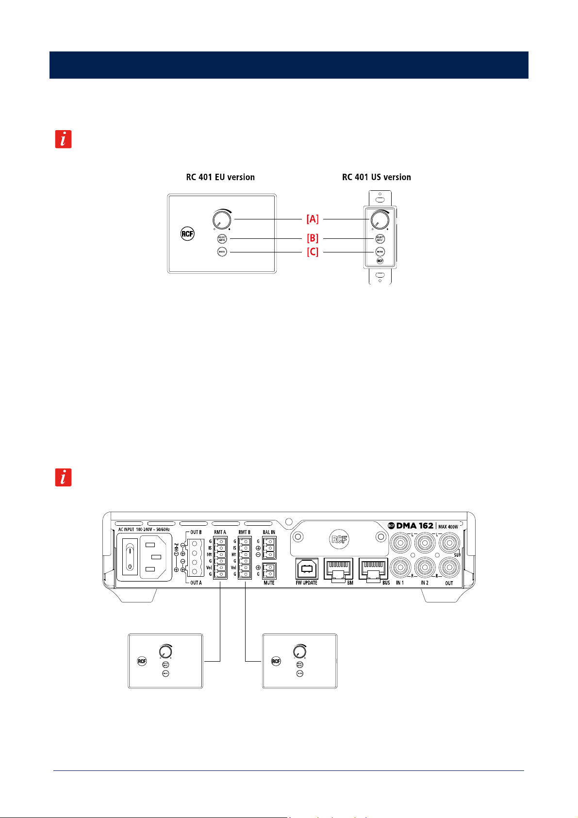
Figure 2
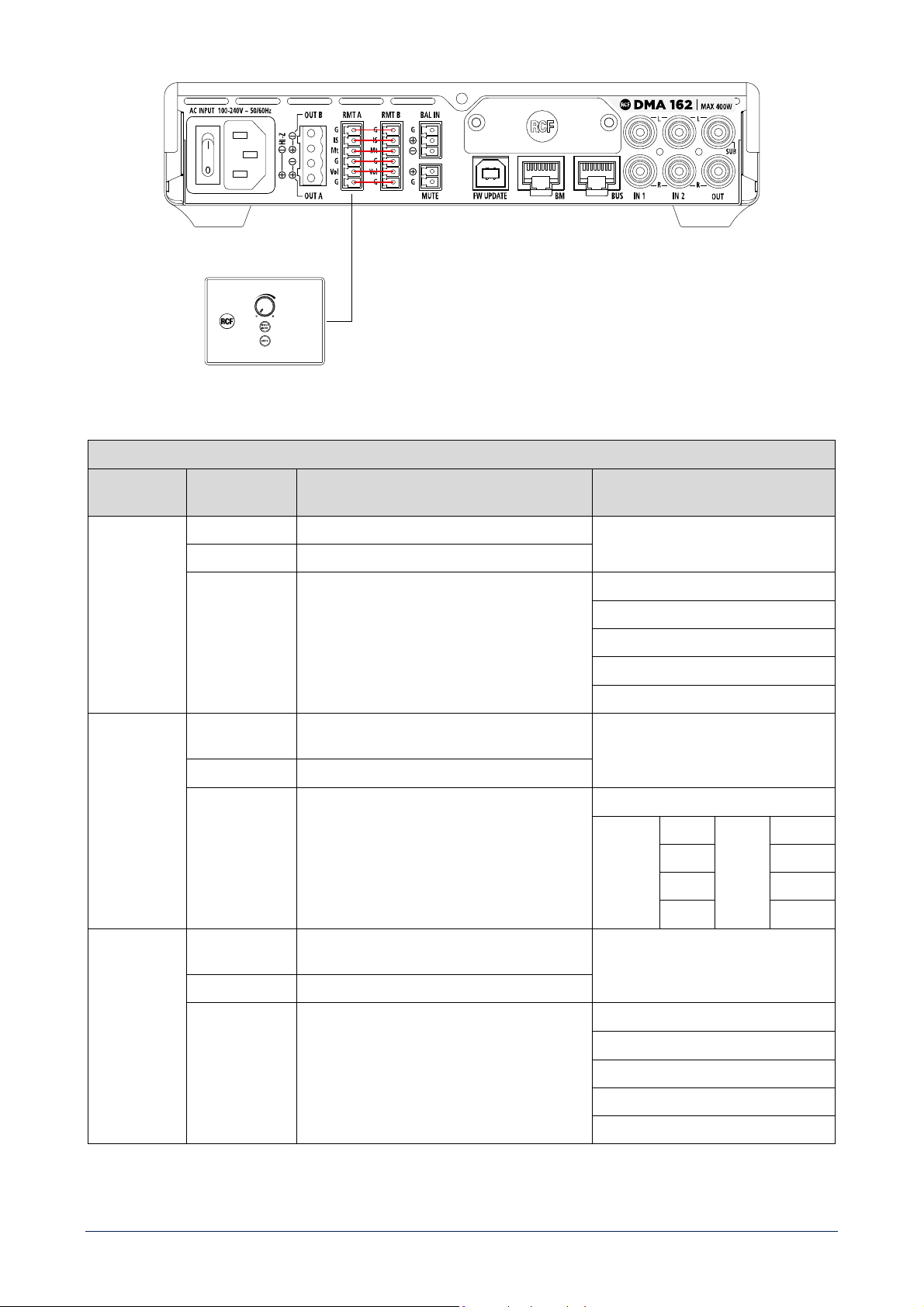
RMT A
AMPLIFIER
SETTING
COMMAND FUNCTION
MONO
VOLUME Acts on OUT A VOLUME only
MUTE Acts on OUT A MUTE only
SELECT INPUT Acts on OUT A INPUT SELECTION only
INPUTS ROUTING
IN1 MONO
IN2 MONO
EXT MONO
BAL IN
STEREO
VOLUME Acts on OUT A and OUT B VOLUME at the same
time
MUTE Acts on OUT A and OUT B MUTE at the same time
SELECT INPUT If BAL IN is selected, routes the same input on
OUT A and OUT B; if a stereo input is selected,
routes LEFT channel on OUT A and RIGHT channel
on OUT B
INPUTS ROUTING
OUT A IN1 L OUT B IN1 R
IN2 L IN2 R
EXT L EXT R
BAL IN BAL IN
BRIDGE
VOLUME Acts on OUT A and OUT B VOLUME at the same
time; BUS OUT B polarity will be shifted
MUTE Acts on OUT A and OUT B MUTE at the same time
SELECT INPUT Routes the same input for OUT A and OUT B
(mono)
INPUTS ROUTING
IN1 MONO
IN2 MONO
EXT MONO
BAL IN
20
RMT B
AMPLIFIER
SETTING
COMMAND FUNCTION
MONO
VOLUME Acts on OUT B VOLUME only
MUTE Acts on OUT B MUTE only
SELECT INPUT Acts on OUT B INPUT SELECTION only
INPUTS ROUTING
IN1 MONO
IN2 MONO
EXT MONO
BAL IN
APPLICATIONS
Single unit – 2 zones (Figure 1)
STEREO /
BRIDGE
VOLUME Acts on BUS OUT 3 VOLUME only
MUTE Acts on BUS OUT 3 MUTE only
SELECT INPUT Acts on BUS OUT 3 INPUT SELECTION only
INPUTS ROUTING
IN1 MONO
IN2 MONO
EXT MONO
BAL IN
APPLICATIONS
2 units - 2.1 system - RMT A is used only and a
parallel between RMT A and RMT B is needed
(Figure 2)
2 or more units – 2 zones bridge or 70 V.
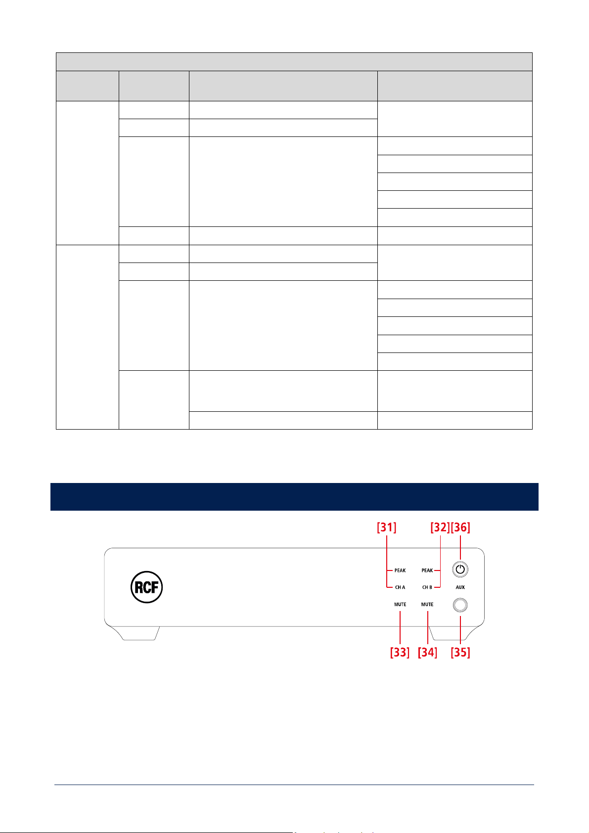
DMA 162P FRONT PANEL
[31] CH A / PEAK (two LEDs): CH A is lit when the audio signal is present on the channel A. PEAK blinks when the signal level of
the channel A reaches the clipping point, causing the limiter intervention; if it is steady lit, its volume level is excessive and needs to
be reduced.
[32] CH B / PEAK (two LEDs): CH B is lit when the audio signal is present on the channel B. PEAK blinks when the signal level of the
channel B reaches the clipping point, causing the limiter intervention; if it is steady lit, its volume level is excessive and needs to be
reduced.
21
[33] CHANNEL A MUTE (LED): when lit, the channel A output is muted.
[34] CHANNEL B MUTE (LED): when lit, the channel B output is muted.
[35] AUX input (3.5 mm stereo TRS jack).
To enable it, BUS / LOCAL [49] contacts (on the rear panel) need to be shorted. If a jack plug is inserted into this input, the rear
panel LOCAL INPUT [41], [42] is disabled.
[36] STAND-BY button with LED: push to toggle the amplifier on/stand-by.
The LED is lit white when the amplifier is turned on, red when the amplifier is in stand-by.
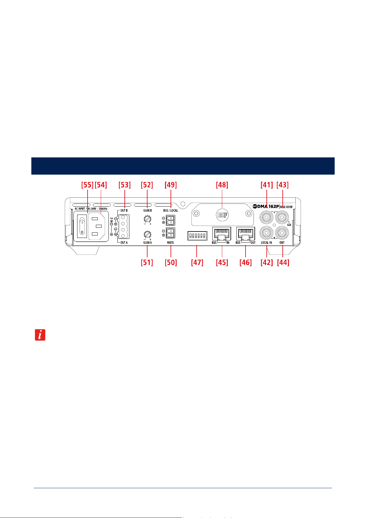
DMA 162P REAR PANEL
[41] LOCAL INPUT (left channel): unbalanced line level input with RCA socket useful to link a local music source. To enable this
input, BUS / LOCAL [49] contacts need to be shorted.
[42] LOCAL INPUT (right channel): unbalanced line level input with RCA socket useful to link a local music source. To enable this
input, BUS / LOCAL [49] contacts need to be shorted.
If a jack plug is inserted into the front panel AUX input [35], the rear panel audio LOCAL IN [41], [42] is momentary disabled.
[43] AUDIO OUTPUT (left channel) / SUB OUT: unbalanced line level output with RCA socket. It can be set to send either a copy of
the output A audio signal or the same signal filtered by a low-pass filter (80 Hz) useful for connecting an active subwoofer.
[44] AUDIO OUTPUT (left channel) / SUB OUT: unbalanced line level output with RCA socket. It can be set to send either a copy of
the output A audio signal or the same signal filtered by a low-pass filter (80 Hz) useful for connecting an active subwoofer.
[45] BUS input (RJ45 socket): it needs to be linked to the BUS output of either the DMA 82/162 main unit (/ amplifier) or the previous
DMA[P] amplifier.
[46] BUS output (RJ45 socket): it needs to be linked to the BUS input of the next DMA[P] amplifier.
[47] DIP-SWITCHES (down: Off, up: ON). [1..6] from left to right.
When the BUS / LOCAL
[49] contacts are open (audio from the 4-channel BUS):
22
1
BRIDGE / MONO
Set BRIDGE or MONO mode
2
SUB / AUX
If set to
SUB
, the rear panel OUT / SUB [43]
, [44] outputs are
affected by a 80 Hz low-pass filter for connecting active subwoofers.
3
CHANNEL SELECTION A
Audio output A channel selection (see the next table)
4
5
CHANNEL SELECTION B
Audio output B channel selection (see the next table)
6
OUT DIP 3 DIP 4 SEL. BUS CH
OUT DIP 5 DIP 6 SEL. BUS CH
A
Off Off 1
B
Off Off 1
Off ON 2 Off ON 2
ON Off 3 ON Off 3
ON ON 4 ON ON 4
When the BUS / LOCAL [49] contacts are shorted (audio from the LOCAL IN only):
1
BASS ENANCHER OFF / ON
If set to BASS ON, it turns on the bass enhancer on all outputs
2
SUB / AUX
If set to
SUB
, the rear panel OUT / SUB [43], [44] outputs are
affected by a 80 Hz
3 Not used
4
DUAL IN
If set ON (together with BRIDGE and STEREO Off), enables a
functionality with 2 mono channels and independent volumes.
5
BRIDGE
Is set ON enable BRIDGE MODE
6
STEREO / MONO
If BRIDGE is set Off, enables STEREO or MONO MODE
Dip-switch functionalities undergo this priority: BRIDGE > STEREO > DUAL IN > MONO.
[48] Blank panel to be removed when installing the optional RDNET board.
[49] BUS / LOCAL(removable screw terminal block), logic input for dry contact:
When its contacts are open, DMA[P] amplifier receives audio signals from the BUS IN [45] (and its LOCAL IN is muted).
When its contacts are shorted, DMA[P] amplifier is directly linked to its LOCAL IN [41], [42] only.
[50] MUTE (removable screw terminal block): remote mute command (a dry closing contact) active when its contacts are shorted.
[51] GAIN A: turn it clockwise to increase the OUT A level or counterclockwise to reduce it.
[52] GAIN B: turn it clockwise to increase the OUT B level or counterclockwise to reduce it.
When STEREO or BRIDGE functional modes are activated, GAIN A acts on both OUT A and OUT B.
23
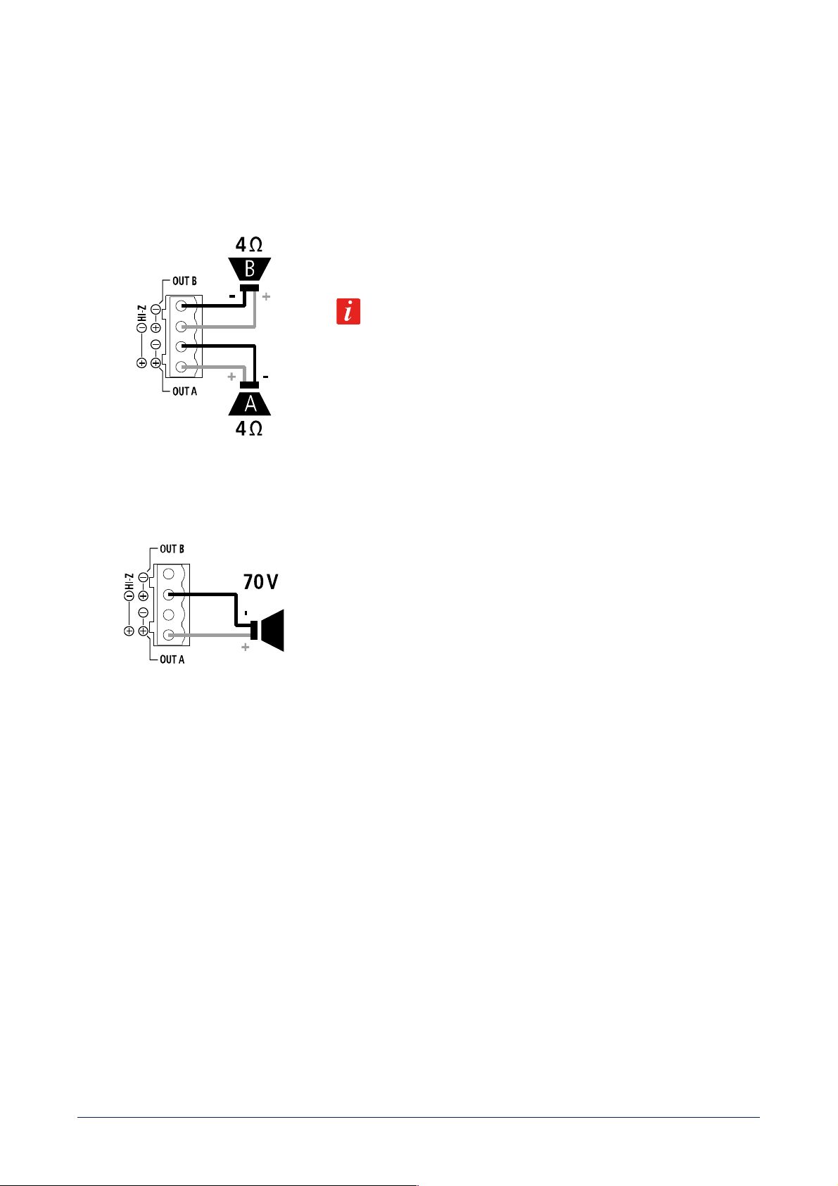
[53] SPEAKER OUTPUTS
DMA[P] amplifier speaker outputs allow either two channels for a low-impedance connection or a single 70 V line for speakers having
matching transformers.
Connector: EUROBLOCK (removable screw terminal block).
TWO CHANNELS (A, B) --- LOW IMPEDANCE CONNECTION (4 Ω)
Connect speakers as shown in the figure.
Minimum load impedance is 4 Ω per speaker output.
DELIVERED POWER 2 x 160 W RMS @ 4 Ω
An impedance equal to 4 Ω allows to get the max. power (80 / 160 W).
A higher impedance leads to a reduction of the delivered power (e.g. 8 Ω: ca. 40
/ 80 W), an impedance lower than 4 Ω overloads the amplifier.
BRIDGE MODE OR HI IMPEDANCE 70 V
Connect speakers as shown in the figure.
BRIDGE MODE
Channels A, B are bridged by setting the BRIDGE MODE to ON (see the
next manual sections ‘DMA 82 / DMA 162 operation modes’ and ‘DMA 82 / DMA
162 settings’) and can work both at low impedance speakers and hi impedance
(70 V).
Do NOT connect the other two contacts.
The overall speaker power shall not exceed 160 W (DMA 82) / 320 W (DMA 162).
[54] Power cord input.
Connect the power cord only to a mains socket outlet with a protective earthing connection.
[55] Power switch: push to turn on (I) / off (O) the amplifier.
24
AVVERTENZE PER LA SICUREZZA
I simboli utilizzati in questo documento notificano importanti istruzioni operative e avvertimenti che devono essere seguiti
attentamente.
CAUTELA
Importante istruzione operativa: notifica un pericolo che potrebbe danneggiare il
prodotto, compresa la perdita di dati.
ATTENZIONE
Avvertimento importante riguardante l’uso di voltaggi pericolosi e il potenziale
rischio di shock elettrico, lesioni personali o morte.
NOTE IMPORTANTI
Informazioni utili e rilevanti sull’argomento.
SUPPORTI, TROLLEY E
CARRRELLI
Informazioni riguardanti l’utilizzo di supporti, trolley e carrelli. Suggerisce di
muovere con estrema cautela e di non inclinare il carico.
SMALTIMENTO
Questo simbolo indica che il prodotto non deve essere smaltito con i rifiuti ordinari,
così come indicato nella direttiva WEEE (2012/19/ EU) e nelle normative nazionali
in vigore.
NOTE IMPORTANTI
Questo manuale contiene informazioni importanti sull’uso corretto e sicuro del dispositivo. Prima di collegare e utilizzare questo
prodotto, leggere attentamente questo manuale di istruzioni e tenerlo a portata di mano per riferimenti futuri. Il manuale deve essere
considerato parte integrante di questo prodotto e deve accompagnarlo in caso di cambio proprietà come riferimento per la corretta
installazione e utilizzo nonché per le precauzioni di sicurezza. RCF S.p.A. non si assume alcuna responsabilità per l’installazione e / o
l’uso errati di questo prodotto.
PRECAUZIONI DI SICUREZZA
1. Tutte le precauzioni, in particolare quelle di sicurezza, devono essere lette con particolare attenzione, in quanto forniscono
informazioni importanti.
2. Alimentazione principale da rete elettrica
a. La tensione di rete è sufficientemente elevata da comportare un rischio di folgorazione; installare e collegare questo prodotto
prima di collegarlo.
b. b. Prima di accendere, assicurarsi che tutti i collegamenti siano stati eseguiti correttamente e che la tensione della rete
corrisponda alla tensione indicata sulla targhetta dei dati sull’unità, in caso contrario, contattare il rivenditore RCF.
c. Le parti metalliche dell’unità sono messe a terra attraverso il cavo di alimentazione. Un apparecchio con costruzione di CLASSE
I deve essere collegato a una presa di corrente con un collegamento di terra di protezione.
d. Proteggere il cavo di alimentazione da danni; assicurarsi che sia posizionato in modo tale da non poter essere calpestato o
schiacciato da oggetti.
e. Per evitare il rischio di scosse elettriche, non aprire mai questo prodotto: non sono previste parti interne alle quali l’utente debba
accedere.
f. Fare attenzione: nel caso di un prodotto provvisto solo di connettori POWERCON e senza cavo di alimentazione, congiuntamente
ai connettori POWERCON tipo NAC3FCA (alimentazione) e NAC3FCB (alimentazione), devono essere usati i seguenti cavi di
alimentazione conformi alla norma nazionale:
- EU: cavo di tipo H05VV-F 3G 3x2.5 mm2 - Standard IEC 60227-1
- JP: cavo di tipo VCTF 3x2 mm2; 15Amp/120V~ - Standard JIS C3306
- US: cavo di tipo SJT/SJTO 3x14 AWG; 15Amp/125V~ - Standard ANSI/UL 62

25
3. Assicurarsi che nessun oggetto o liquido penetri in questo prodotto poiché ciò potrebbe causare un corto circuito. Questo
apparecchio non deve essere esposto a gocciolamenti o spruzzi. Nessun oggetto riempito di liquido, come vasi, deve essere
posizionato su questo apparecchio. Nessuna fiamma libera (come candele accese) deve essere posizionata su questo
apparecchio.
4. Non tentare mai di eseguire operazioni, modifiche o riparazioni non espressamente descritte nel presente manuale. Contattare
il centro di assistenza autorizzato o personale qualificato qualora si verifichi una delle seguenti condizioni:
- Il prodotto non funziona (o funziona in modo anomalo).
- Il cavo di alimentazione è stato danneggiato.
- Oggetti o liquidi sono entrati nell’unità.
- Il prodotto ha subìto un forte urto.
5. Se questo prodotto non viene utilizzato per un lungo periodo, scollegare il cavo di alimentazione.
6. Se questo prodotto inizia a emettere strani odori o fumo, spegnerlo immediatamente e scollegare il cavo di alimentazione.
7. Non collegare questo prodotto ad apparecchiature o accessori non previsti. Per l’installazione sospesa, utilizzare solo i punti di
ancoraggio dedicati e non tentare di appendere questo prodotto utilizzando elementi non idonei o non specifici per questo scopo.
Verificare inoltre l’idoneità della superficie di supporto a cui è ancorato il prodotto (parete, soffitto, struttura, ecc.) a dei
componenti utilizzati per il fissaggio (tasselli, viti, staffe non fornite da RCF ecc.) che devono garantire sicurezza del sistema /
installazione nel tempo, anche considerando, ad esempio, le vibrazioni meccaniche normalmente generate dai trasduttori. Per
evitare il rischio di caduta dell’apparecchiatura, non impilare più unità di questo prodotto a meno che questa possibilità non sia
specificata nel manuale dell’utente.
8. RCF S.p.A. raccomanda vivamente che questo prodotto sia installato solo da installatori professionisti qualificati (o aziende
specializzate) che possono garantire la corretta installazione e certificarlo secondo le normative vigenti. L’intero sistema audio
deve essere conforme agli standard e alle normative vigenti in materia di sistemi elettrici.
9. Supporti, trolley e carrelli.
L’apparecchiatura deve essere utilizzata, ove necessario, solo su supporti, trolley e carrelli consigliati dal produttore.
L’apparecchiatura / supporto / carrello deve essere spostata con estrema cautela. Arresti improvvisi, eccessiva spinta e pavimenti
irregolari possono causarne il ribaltamento. Non inclinare mai.
10. Vi sono numerosi fattori meccanici ed elettrici da considerare quando si installa un sistema audio professionale (oltre a quelli
strettamente acustici, come la pressione del suono, gli angoli di copertura, la risposta in frequenza, ecc.).
11. Perdita dell’udito. L’esposizione a livelli sonori elevati può causare la perdita permanente dell’udito. Il livello di pressione acustica
che porta alla perdita dell’udito è diverso da persona a persona e dipende dalla durata dell’esposizione. Per prevenire
un’esposizione potenzialmente pericolosa a livelli elevati di pressione acustica, chiunque sia esposto a questi livelli dovrebbe
usare adeguati dispositivi di protezione. Quando viene utilizzato un trasduttore in grado di produrre alti livelli sonori, è quindi
necessario indossare tappi per le orecchie o cuffie protettive. Vedere le specifiche tecniche del manuale per conoscere il livello
massimo di pressione sonora.
PRECAUZIONI OPERATIVE
- Posizionare questo prodotto lontano da qualsiasi fonte di calore e garantire sempre un’adeguata circolazione dell’aria attorno
ad esso.
- Non sovraccaricare questo prodotto per molto tempo.
- Non forzare mai gli elementi di controllo (tasti, manopole, ecc.).
- Non utilizzare solventi, alcool, benzene o altre sostanze volatili per pulire le parti esterne di questo prodotto.
NOTE IMPORTANTI
Per evitare il verificarsi di disturbi sui cavi di segnale in linea, utilizzare solo cavi schermati ed evitare di avvicinarli a:
- Apparecchiature che producono campi elettromagnetici ad alta intensità
- Cavi di alimentazione
26
- Linee di altoparlanti
ATTENZIONE! CAUTELA! Per evitare il rischio di incendi o scosse elettriche, non esporre mai
questo prodotto a pioggia o umidità.
ATTENZIONE! Per evitare il rischio di scosse elettriche, non collegare all’alimentazione di rete mentre la
griglia è rimossa.
WARNING! Per ridurre il rischio di scosse elettriche, non smontare questo prodotto se non si è qualificati.
Per l’assistenza rivolgersi a personale di assistenza qualificato.
SMALTIMENTO CORRETTO DEL PRODOTTO
Questo prodotto deve essere consegnato a un sito di raccolta autorizzato per il riciclaggio di apparecchiature elettriche ed elettroniche
(AEE). Una manipolazione impropria di questo tipo di rifiuti potrebbe avere un possibile impatto negativo sull’ambiente e sulla salute
umana a causa di sostanze potenzialmente pericolose che sono generalmente associati alle AEE. Allo stesso tempo, la vostra
collaborazione per il corretto smaltimento di questo prodotto contribuirà all’utilizzo efficace delle risorse naturali. Per ulteriori
informazioni su dove sia possibile scaricare le attrezzature per il riciclaggio, si prega di contattare l’ufficio comunale locale, l’autorità
competente per i rifiuti o il servizio di smaltimento dei rifiuti domestici.
CURA E MANUTENZIONE
Per garantire un servizio di lunga durata, questo prodotto deve essere utilizzato seguendo questi consigli:
- Se il prodotto deve essere installato all’aperto, assicurarsi che sia coperto e protetto da pioggia e umidità.
- Se il prodotto deve essere utilizzato in un ambiente freddo, riscaldare lentamente le bobine vocali inviando un segnale di basso
livello per circa 15 minuti prima di inviare segnali ad alta potenza.
- Utilizzare sempre un panno asciutto per pulire le superfici esterne dell’altoparlante e farlo sempre quando l’alimentazione è
spenta
CAUTELA! Per evitare di danneggiare le finiture esterne non utilizzare solventi per la pulizia o abrasivi.
ATTENZIONE! CAUTELA! Per gli altoparlanti alimentati, eseguire la pulizia solo quando
l’alimentazione è spenta.
NOTE FCC
Questa apparecchiatura è stata testata ed è risultata conforme ai limiti per un dispositivo digitale di Classe A, ai sensi della Parte 15
delle norme FCC. Questi limiti sono progettati per fornire una protezione ragionevole contro interferenze dannose quando
l'apparecchiatura viene utilizzata in un ambiente commerciale. Questa apparecchiatura genera, utilizza e può irradiare energia in
radiofrequenza e, se non viene installata e utilizzata secondo il manuale di istruzioni, può causare interferenze dannose alle
comunicazioni radio. È probabile che il funzionamento di questa apparecchiatura in un'area residenziale provochi interferenze
dannose, nel qual caso l'utente dovrà correggere l'interferenza a proprie spese.
Modifiche: qualsiasi modifica apportata a questo dispositivo che non sia approvata da RCF può annullare l'autorizzazione concessa
all'utente dalla FCC di utilizzare questa apparecchiatura.

27
RCF S.p.A. Vi ringrazia per l’acquisto di questo prodotto, realizzato in modo da garantirne l’affidabilità e prestazioni
elevate.
INTRODUZIONE AI PRODOTTI DELLA LINEA BUSINESS MUSIC
La linea BUSINESS MUSIC include amplificatori e matrici digitali DMA 82 / DMA 162, amplificatori digitali DMA 162P (nel seguito
chiamati anche DMA[P]), basi microfoniche per annunci BM 404, controlli remoti e diffusori acustici, offrendo un sistema audio
completo e massimizzando le prestazioni acustiche complessive. Gli amplificatori DMA / DMA[P] sono estremamente compatti (1/2
unità rack 19” in larghezza ed 1 unità in altezza), ideali per l’installazione su banco oppure a rack (con accessori opzionali) ed adatti
per una vasta gamma di soluzioni di sistema, dai negozi al bar e ristoranti, sale riunioni, istruzione o strutture pubbliche e qualsiasi
applicazione audio/video. Il loro design accurato, unito alla solidità ambientale (grado di protezione IP 30 e dissipazione termica ad
alta efficienza), rappresenta un punto di congiunzione tra i mercati professionali e quelli “consumer”. Questa linea include sia diffusori
da soffitto sia da parete con prestazioni acustiche professionali ed un elevato design industriale. Sono presenti diversi livelli di
configurazione, dal pannello di controllo frontale facile da usare alla rete RCF “RDNet” per sistemi grandi e complessi con una
architettura scalabile. L’unità di controllo può inviare fino a quattro canali mono / due stereo ai satelliti tramite un singolo cavo CAT5.
Ciò consente di aumentare la potenza installata e creare un’architettura per più ambienti con una semplice connessione tra i dispositivi.
DMA 82 / DMA 162: DESCRIZIONE E CARATTERISTICHE PRINCIPALI
DMA 82 e DMA 162 sono amplificatori (con matrice) in classe D a due canali, entrambi dotati di una potente piattaforma DSP che
consente di gestire gli ingressi e le uscite audio e l’equalizzazione (è disponibile un set completo di funzioni di elaborazione, inclusi
equalizzatori parametrici, filtri FIR, un incremento delle basse frequenze “bass enhancer”, limitatori, compressori ed equalizzazione
ambientale); inoltre, sono stati implementati dei preset specifici per i diffusori acustici RCF in modo da ottimizzare le loro prestazioni
acustiche. I due modelli differiscono solo nella loro potenza d’uscita:
- DMA 82 2 canali x 80 W RMS su 4 Ω oppure una singola linea 70 V - 160 W;
- DMA 162 2 canali x 160 W RMS su 4 Ω oppure una singola linea 70 V - 320 W.
Ciascun amplificatore DMA può essere posto su banco oppure installato in un armadio rack 19” (grazie ad un accessorio opzionale).
Ogni unità ha 2 ingressi audio LINE stereo su connettori RCA, 1 ingresso audio bilanciato MIC o LINE su terminali a vite rimovibili e
un’uscita audio LINE con filtro passa-basso (disinseribile) utile per il collegamento ad un subwoofer attivo. Un ingresso dedicato con
connettore RJ 45 permette la connessione di max. 4 basi microfoniche per annunci BM 404 (collegate in cascata sulla stessa linea ed
interbloccate tra loro). Un controllo remoto RC 401 (da parete) può essere collegato per ciascun canale d’uscita in modo da regolarne
il livello di volume e per la selezione dell’ingresso audio desiderato. L’unità centrale DMA può inviare fino a 4 canali audio a quelle
satelliti DMA[P] tramite un BUS con un singolo cavo CAT5, combinando un’architettura per più ambienti flessibile e scalabile e con
una connessione ed installazione semplici. La sua configurazione è intuitiva e può essere eseguita tramite i controlli del pannello
anteriore (con display OLED) o “RDNet” (quando la scheda opzionale è installata).
DMA 162P: DESCRIZIONE E CARATTERISTICHE PRINCIPALI
DMA 162P è un amplificatore in classe D a due canali. Potenza d’uscita: 2 canali x 160 W RMS su 4 Ω - oppure una singola linea 70
V - 320 W. È possibile collegare fino a quattro DMA[P] ad un singolo DMA per aumentare la potenza d’uscita del sistema ed
implementare architetture per più ambienti; tuttavia, ciascun DMA[P] può essere utilizzato anche come amplificatore autonomo.
Ciascun amplificatore DMA[P] può essere posto su banco oppure installato in un armadio rack 19” (grazie ad un accessorio opzionale).
DMA[P] può ricevere segnali audio processati da un amplificatore DMA tramite BUS audio a quattro canali (quattro mono od uno
stereo e due mono o due stereo, i quattro segnali sono gli stessi inviati agli amplificatori DMA), o in alternativa, è possibile selezionare
l’ingresso LINE stereo locale (cortocircuitando il contatto dedicato). È disponibile anche un’uscita LINE, con un filtro passa-basso per

28
la connessione ad un subwoofer attivo. La sua configurazione può essere eseguita tramite i dip-switch sul pannello posteriore oppure
la rete “RDNet” (quando è installata la scheda opzionale).
DISIMBALLAGGIO, INSTALLAZIONE E RAFFREDDAMENTO
Controllare l’imballo ed il suo contenuto e verificare se c’è qualche segno di danno (se l’amplificatore è danneggiato, informare
immediatamente il proprio distributore / rivenditore locale e lo spedizioniere). È sempre consigliabile conservare i materiali
d’imballaggio, anche se l’amplificatore è arrivato in buone condizioni; il cavo d’alimentazione è incluso. Gli amplificatori DMA / DMA[P]
possono essere installati in un armadio rack da 19” (è richiesto un accessorio opzionale per ogni coppia, poiché ogni amplificatore
richiede metà unità rack). Gli amplificatori non dovrebbero essere installati in un luogo con:
- temperatura troppo elevata, polvere o umidità eccessiva;
- ventilatori per il ricambio d’aria;
- vibrazioni permanenti;
- campi elettromagnetici ad alta intensità (dovuti a trasformatori, trasmettitori, ecc.).
Assicurarsi che vi sia una ventilazione adeguata e che ai lati dell’amplificatore vi sia uno spazio sufficiente. La temperatura all’interno
dell’armadio rack deve essere mantenuta al di sotto dei 35°C. Per motivi di sicurezza, non togliere mai la messa a terra del cavo di
alimentazione. Utilizzare cavi audio schermati per evitare ronzii e interferenze.
29
DIAGRAMMA A BLOCCHI DEL SEGNALE AUDIO
30
DMA 82 / DMA 162: PANNELLO FRONTALE
[1] Display (OLED). Quando nessun menu e selezionato, i livelli correnti dei segnali audio d’uscita sono visualizzati come barre.
[2] Encoder rotativo e pulsante per selezionare. Ruotare l’encoder in senso orario per aumentare il volume principale (MASTER
VOLUME) o in senso antiorario per diminuirlo. Premerlo per mettere tutto in “mute” (disattivato) o ripristinare il suono. All’interno
di un menu (dopo aver premuto MENU [3]): ruotare l’encoder in senso orario per far scorrere il menu verso il basso o aumentare il
valore del parametro selezionato, ruotarlo in senso antiorario per far scorrere il menu verso l’alto o diminuire il valore del parametro
selezionato. Premere per selezionare (ed eventualmente entrare in un sottomenu).
[3] Tasto MENU: premere per accedere al menu principale (HOME) nella modalità di modifica dei parametri.
[4] Tasto BACK / ESC: premere per uscire dal menu visualizzato sul display.
[5] CH A / PEAK (due LED): CH A si accende quando e presente un segnale sul canale A. PEAK lampeggia quando il livello del segnale
del canale A raggiunge il punto di clipping, causando l’intervento del limitatore interno; se acceso fisso, il livello e eccessivo e deve
essere ridotto.
[6] CH B / PEAK (due LED): CH B si accende quando e presente un segnale sul canale B. PEAK lampeggia quando il livello del segnale
del canale B raggiunge il punto di clipping, causando l’intervento del limitatore interno; se acceso fisso, il livello e eccessivo e deve
essere ridotto.
[7] CH A MUTE (LED): quando e acceso, l’uscita del canale A e disattivata.
[8] CH B MUTE (LED): quando e acceso, l’uscita del canale B e disattivata.
[9] Ingresso audio AUX (jack stereo TRS da 3,5 mm).
Se un connettore jack e inserito in questo ingresso, l’ingresso IN 1 [11], [12] posteriore è disabilitato.
[10] Tasto STAND-BY con LED: premere per attivare o mettere in “stand-by” l’amplificatore.
Il LED si accende bianco quando l’amplificatore e in funzione, rosso quando e in stand-by.
31
DMA 82 / DMA 162: PANNELLO POSTERIORE
[11] Ingresso audio IN 1 (canale sinistro): ingresso di linea sbilanciato con presa RCA.
[12] Ingresso audio IN 1 (canale destro): ingresso di linea sbilanciato con presa RCA.
Se un connettore jack e inserito nell’ingresso AUX [9] del pannello frontale, l’ingresso IN 1 [11], [12] sul retro e
momentaneamente disabilitato.
[13] Ingresso audio IN 2 (canale sinistro): ingresso di linea sbilanciato con presa RCA.
[14] Ingresso audio IN 2 (canale destro): ingresso di linea sbilanciato con presa RCA.
[15] Uscita audio OUT (canale sinistro) / SUB: uscita di linea sbilanciata con presa RCA. Può essere impostata per inviare una copia
del segnale audio presente all’uscita A (BUS 1; canale sinistro se stereo) o lo stesso segnale filtrato da un filtro passa-basso (80 Hz)
utile per collegare un subwoofer attivo.
[16] Uscita audio OUT (canale destro) / SUB: uscita di linea sbilanciata con presa RCA. Può essere impostata per inviare una copia
del segnale audio presente all’uscita B (BUS 2; canale destro se stereo) o lo stesso segnale filtrato da un filtro passa-basso (80 Hz)
utile per collegare un subwoofer attivo.
[17] Uscita BUS (presa RJ45): deve essere collegata all’ingresso BUS del primo amplificatore DMA[P] (se presente).
CONTATTO USCITA AUDIO BUS COLORE CONDUTTORE
(T568B)
1 1 - Bianco - arancio
2 1 + Arancio
3 2 - Bianco --- verde
4 3 - Blu
5 3 + Bianco --- blu
6 2 + Verde
7 4 - Bianco --- marrone
8 4 + Marrone
32
[18] BM: ingresso (presa RJ45) per le basi microfoniche BM 404. Fino a quattro basi microfoniche BM 404 possono essere collegate
in cascata (sulla stessa linea).
CONTATTO USCITA AUDIO BUS COLORE CONDUTTORE
(T568B)
1 SEGNALE AUDIO --- Bianco - arancio
2 SEGNALE AUDIO + Arancio
3 MASSA Bianco --- verde
4 ABILITAZIONE ANNUNCI Blu
5 SELEZIONE ZONA A Bianco --- blu
6 SELEZIONE ZONA B Verde
7 SELEZIONE ZONA C Bianco --- marrone
8 SELEZIONE ZONA D Marrone
In alternativa (quando non sono presenti basi microfoniche BM 404), questa presa può essere utilizzata anche come ingresso audio
ausiliario aggiuntivo collegando solo i primi tre contatti.
[19] FW UPDATE: porta USB (tipo B) per collegare localmente un computer (PC). Questa porta può essere utilizzata per controllare
l’amplificatore tramite il software RDNET oppure per aggiornare il firmware.
[20] Pannello cieco da rimuovere durante l’installazione della scheda opzionale RDNET.
[21] BAL IN: ingresso audio bilanciato con morsettiera a vite rimovibile. È dotato della funzione VOX: la rilevazione della presenza di
un segnale al suo ingresso ne determina automaticamente la priorità.
G massa
+ segnale audio +
- segnale audio ---
[22] MUTE: ingresso per contatto pulito per la messa in “mute” (quando cortocircuitato); morsettiera a vite estraibile.
[23] RMT B, [24] RMT A: ingressi (morsettiera a vite rimovibile) per controllo remoto RC 401 opzionale. Per il funzionamento di
questi accessori si veda la specifica sezione del manuale. Il pinout del connettore è riportato nella tabella seguente:
G Massa
Is Selezione ingresso
Mt Mute
G Massa
Vol Volume
G Volume
33
[25] USCITE ALTOPARLANTI
Le uscite per altoparlanti dell’amplificatore DMA consentono connessioni a bassa impedenza su due canali oppure una singola linea
da 70 V per diffusori acustici con trasformatore.
Connettore: EUROBLOCK (morsettiera a vite rimovibile).
DUE CANALI (A, B) COLLEGAMENTO A BASSA IMPEDENZA (4 Ω)
Collegare gli altoparlanti come mostrato in figura.
Impedenza minima del carico: 4 Ω per canale.
POTENZA EROGATA
DMA 82: 2 x 80 W RMS su 4 Ω
DMA 162: 2 x 160 W RMS su 4 Ω
Un'impedenza pari a 4 Ω consente di ottenere la massima potenza (80/160 W).
Un'impedenza più elevata porta a una riduzione della potenza erogata (ad es. 8
Ω: circa 40/80 W); un'impedenza inferiore a 4 Ω sovraccarica l’amplificatore.
SINGOLA LINEA 70 V
Collegare la linea per altoparlanti come mostrato in figura.
I due canali sono messi ‘‘a ponte’’ tramite l’impostazione del
parametro MODALITA BRIDGE su ON nel menu (vedere le successive sezioni
del manuale “DMA 82 / DMA 162: modalità di funzionamento” e “DMA 82 /
DMA 162: impostazioni”) in modo da ottenere una singola linea a 70 V.
NON collegare gli altri due contatti. Tutti i diffusori acustici dovranno avere un
trasformatore con ingresso 70 V.
La potenza totale complessiva dei diffusori acustici non dovrà eccedere il valore
di 160 W (DMA 82) o 320 W (DMA 162).
[26] Ingresso per il cavo d’alimentazione. Collegare il cavo d’alimentazione solo ad una presa di corrente avente la messa a terra.
[27] Interruttore principale: premere per accendere (I) oppure spegnere (O) l’amplificatore.
DMA 82 / DMA 162: MODALITÀ DI FUNZIONAMENTO
Dopo aver inserito la password corretta (menu: IMPOSTAZIONI > PASSWORD), e possibile impostare la modalità di funzionamento
tra le opzioni: mono, stereo, bridge. Per scegliere la modalità STEREO, selezionare il parametro MODALITA STEREO ed impostarlo su
ON; per scegliere la modalità BRIDGE (“a ponte”, singola linea a 70 V), selezionare il parametro MODALITA BRIDGE ed impostarlo
su ON. I due parametri MODALITA STEREO e MODALITA BRIDGE si escludono a vicenda: attivandone uno, l’altro si disattiva
automaticamente; per la modalità MONO, lasciare entrambi i parametri su OFF.
34
DIAGRAMMA A BLOCCHI DEI CONTROLLI DI VOLUME DELLE USCITE
Nota: TUTTE LE USCITE è sempre il volume principale (“master”) comune delle uscite.
MONO
Le due uscite A e B sono indipendenti e hanno controlli di volume separati: USCITA A e USCITA B.
STEREO
L’amplificatore DMA puo gestire ingressi stereo.
STEREO1 e il volume comune per entrambi i canali sinistro (A) e destro (B).
USCITA 1L e USCITA 1R sono i controlli di volume per i singoli canali (utili per il bilanciamento).
BRIDGE (“a ponte”)
Le due uscite sono messe ‘‘a ponte’’ in modo da ottenere una singola linea a 70 V (mono).
BRIDGE1 e il controllo comune di volume.
35
DMA 82 / DMA 162: IMPOSTAZIONI
Premere il tasto MENU [3] del pannello frontale per accedere al menu principale (HOME).
Ruotare l’encoder [2] in senso orario per scorrere il menu verso il basso od aumentare il valore del parametro selezionato, ruotarlo in
senso antiorario per scorrere il menu verso l’alto o ridurre il valore del parametro selezionato.
Premere l’encoder [2] per selezionare (od entrare eventualmente in un sottomenu).
Premere il tasto BACK / ESC [4] per uscire dal menu visualizzato sul display.
Tutti i parametri evidenziati qui in grigio sono disponibili solo dopo aver inserito (nel menu delle impostazioni) la password corretta
(codice di 4 cifre: 7471). Tutti gli ingressi audio evidenziati qui in grigio sono disponibili solo dopo aver impostato il parametro MOD.
AVANZATA (nel menu delle impostazioni) su ON.
NOTE:
- in modalità STEREO, tutti gli ingressi stereo (IN 1, IN 2, EXT) sono inviati in stereo alle uscite principali A, B e OUT / SUB;
- gli ingressi BAL IN e BM sono sempre inviati in mono a tutte le uscite;
- nel modo avanzato, ingressi mono separati come IN 1L, IN 1R, IN 2L, IN 2R, EXT L e EXT R, quando inviati ad un’uscita
stereo, sono attivi solo nel rispettivo canale (quello sinistro per gli ingressi “L”, quello destro per gli ingressi “R”) e
disabilitati nell’altro.
HOME PAGE (in modalità mono)
USCITA A
si accede al menu USCITA per la sola uscita A
USCITA A
si accede al menu USCITA per la sola uscita B
TUTTE LE USCITE
si accede al menu TUTTE LE USCITE
INGRESSI
si accede al menu INGRESSI
USCITE BUS
si accede al menu USCITE BUS
IMPOSTAZIONI
si accede al menu IMPOSTAZIONI
HOME PAGE (in modalità stereo)
STEREO1
si accede al menu STEREO1
USCITA 1L
si accede al menu USCITA per il solo canale sinistro (uscita A)
USCITA 1R
si accede al menu USCITA per il solo canale destro (uscita B)
TUTTE LE USCITE
si accede al menu TUTTE LE USCITE
INGRESSI
si accede al menu INGRESSI
USCITE BUS
si accede al menu USCITE BUS
IMPOSTAZIONI
si accede al menu IMPOSTAZIONI
HOME PAGE (in modalità bridge, uscita 70 V)
BRIDGE1
si accede al menu BRIDGE1
TUTTE LE USCITE
si accede al menu TUTTE LE USCITE
INGRESSI
si accede al menu INGRESSI
USCITE BUS
si accede al menu USCITE BUS
IMPOSTAZIONI
si accede al menu IMPOSTAZIONI
36
MENU USCITE
VOLUME Regola il livello del volume dell'uscita selezionata
MUTE Silenzia (ON) o ripristina (OFF) l'uscita selezionata
SEL. INGRESSO
Seleziona l'ingresso audio tra: IN 1, IN 2, EXT (ingresso riservato per schede
opzionali), BAL IN, BM (se usato come ingresso aux), IN 1L, IN 1R, IN 2L, IN 2R,
EXT L, EXT R
MODALITÀ STEREO Attiva (ON) o disattiva (OFF) la modalità STEREO
MODALITÀ BRIDGE Attiva (ON) o disattiva (OFF) la modalità BRIDGE
PRESET DIFFUSORI Seleziona il preset adatto per i diffusori acustici utilizzati
FILTRO P-ALTO Selezione della frequenza di taglio del filtro passa-alto sull'uscita
ENFASI BASSI Attiva (ON) o disattiva (OFF) l'enfatizzazione delle basse frequenze
EQ. PARAMETRICI Si accede ad un sottomenu che include due equalizzatori parametrici;
selezionarne uno per modificarne il GUADAGNO, la FREQUENZA e Q (fattore di
merito)
POLARITÀ Inverte (se impostato su ON) la polarità del segnale
STEREO1 MENU (in modalità stereo)
VOLUME Regola il livello del volume di entrambe le uscite
MUTE Silenzia (ON) o ripristina (OFF) entrambe le uscite
SEL. INGRESSO Seleziona l'ingresso audio tra: IN 1, IN 2, EXT (ingresso riservato per schede
opzionali), BAL IN, BM (se usato come ingresso aux), IN 1L, IN 1R, IN 2L, IN 2R,
EXT L, EXT R
MODALITÀ STEREO Attiva (ON) o disattiva (OFF) la modalità STEREO
MODALITÀ BRIDGE Attiva (ON) o disattiva (OFF) la modalità BRIDGE
BRIDGE1 MENU (in modalità bridge)
VOLUME Regola il livello del volume dell'uscita
MUTE Silenzia (ON) o ripristina (OFF) l'uscita (entrambi i canali)
SEL. INGRESSO Seleziona l'ingresso audio tra: IN 1, IN 2, EXT (ingresso riservato per schede
opzionali), BAL IN, BM (se usato come ingresso aux), IN 1L, IN 1R, IN 2L, IN 2R,
EXT L, EXT R
MODALITÀ STEREO Attiva (ON) o disattiva (OFF) la modalità STEREO
MODALITÀ BRIDGE Attiva (ON) o disattiva (OFF) la modalità BRIDGE
PRESET DIFFUSORI Seleziona il preset adatto per i diffusori acustici utilizzati
FILTRO P-ALTO Selezione della frequenza di taglio del filtro passa-alto sull'uscita
ENFASI BASSI Attiva (ON) o disattiva (OFF) l'enfatizzazione delle basse frequenze
EQ. PARAMETRICI Si accede ad un sottomenu che include due equalizzatori parametrici;
selezionarne uno per modificarne il GUADAGNO, la FREQUENZA e Q (fattore di
merito)
POLARITÀ Inverte (se impostato su ON) la polarità del segnale
37
MENU TUTTE LE USCITE
VOLUME regola il livello del volume (master) di tutte le uscite
MUTE silenzia (ON) o ripristina (OFF) tutte le uscite
SEL. INGRESSO
seleziona l'ingresso audio tra: IN 1, IN 2, EXT
(ingresso riservato per schede
opzionali), BAL IN, BM (se usato come ingresso aux), IN 1L, IN 1R, IN 2L, IN 2R,
EXT L, EXT R
MENU INGRESSI
Dopo essere entrati nel menu degli ingressi audio, selezionarne uno tra IN 1, IN 2, EXT (ingresso riservato per
schede opzionali), BAL IN, BM, IN 1L, IN 1R, IN 2L, IN 2R, EXT L o EXT R per modificarne i parametri:
VOLUME Regola il livello dell'ingresso selezionato
EQ. A 3 BANDE Permette di regolare BASSI, MEDI, ALTI
Dopo aver scelto BAL IN, sono disponibili ulteriori tre parametri:
LIVELLO LINE/MIC imposta il livello dell'ingresso BAL IN come LINE oppure MIC
VOX attiva (se impostato su ON) la funzione VOX (priorità automatica quando e
rilevato un segnale audio all'ingresso BAL IN) ed e possibile impostare il livello
di soglia
POLARITÀ inverte (se impostato su ON) la polarità del segnale (solo BAL IN)
MENU USCITE BUS
Dopo essere entrati nel menu delle uscite BUS, selezionare un CANALE (1, 2, 3, 4) oppure SUB /AUX. Dopo
aver selezionato uno dei canali, si accede ad un sottomenu:
VOLUME regola il livello del volume del canale selezionato
EQ. FLAT se impostato su ON, disattiva l'equalizzazione nel canale selezionato
SEL. INGRESSO seleziona l'ingresso audio tra: IN 1, IN 2, EXT (ingresso riservato per schede
opzionali), BAL IN, BM (se usato come ingresso aux), IN 1L, IN 1R, IN 2L, IN 2R,
EXT L, EXT R. Disponibile solo per i CANALI 3 e 4.
Dopo aver selezionato SUB / AUX, e possibile attivare o disattivare la funzione SUB delle uscite posteriori
OUT / SUB [15], [16]. Se impostato su ON, sulle uscite e inserito un filtro passa-basso a 80 Hz, utile per il
collegamento di subwoofer attivi.
MENU IMPOSTAZIONI
PASSWORD
Permette di inserite il codice a 4 cifre (7471) per accedere a tutti i parametri
INFO Mostra le informazioni relative alle versioni firmware e temperatura
dell’amplificatore
NOMI USCITE Permette di assegnare nuovi nomi alle uscite A e B nei menu
IMP. DI FABBRICA Permette di ripristinare le impostazioni di fabbrica
LINGUA Permette di scegliere la lingua per i menu del display
MOD. AVANZATA se impostato su OFF (default), gli ingressi IN 1, IN 2 e EXT sono considerati solo
come coppie stereo; se impostato su ON, sono possibili ulteriori opzioni
38
CONTROLLI REMOTI RC 401
RC 401 è un controllo remote per installazione a muro che funziona collegato alle unità DMA. Un controllo remote può essere collegato
a ciascuna uscita di potenza di una unità DMA e permette di regolarne il volume di uscita, attivare il mute e selezionare il programma
in ingresso.
Quando collegato ad una unità DMA, RC 401 è il solo controllo per il volume di uscita, mentre i controlli
corrispondenti nel menu dell’unità DMA risultano disattivati.
RC 401 offre le seguenti funzionalità:
[A] REGOLAZIONE VOLUME DI USCITA. Permette di regolare il volume di uscita nell’intervallo -36 dB ÷ +12 dB.
[B] SELEZIONE INGRESSO. Permette di scegliere in sequenza gli ingressi dell’unità DMA, nell’ordine IN 1 > IN 2 > BAL IN.
[C] MUTE. Attiva il mute sul volume dell’usicta.
RC 401 si collega sul pannello posteriore dell’unità DMA, con gli appositi connettori a vite rimovibili
- È possibile collegare un dispositivo a ciascuna uscita di potenza dell’unità DMA.
- La massima distanza tra l’unità DMA ed il dispositivo RC 401 è 50m.
- La connessione deve essere effettuata con cavo CAT5 schermato.
Gli schemi di collegamento mostrati in Figura 1 e Figura 2 rappresentano le configurazioni delle applicazioni
descritte nelle tabelle successive.
Figura 1
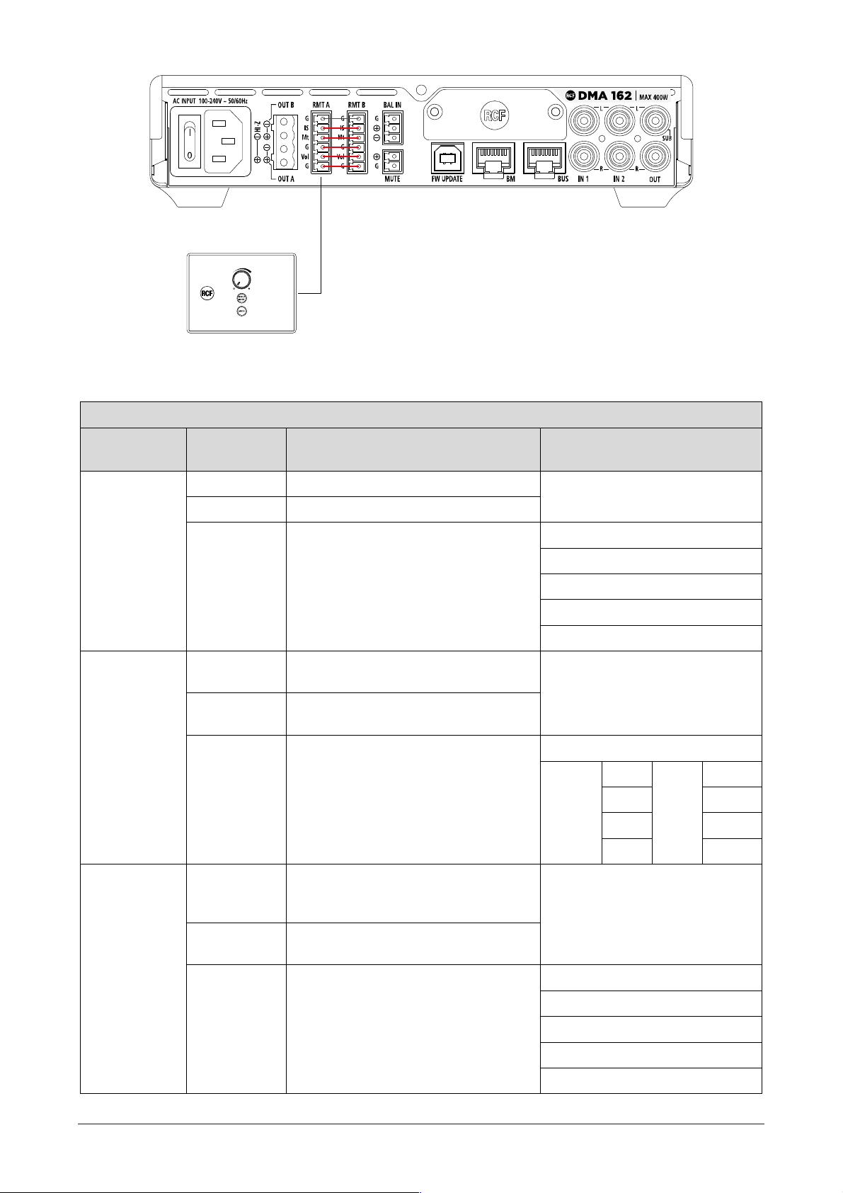
39
Figura 2
RMT A
IMPOSTAZIONE
AMPLIFICATORE
COMANDO FUNZIONE
MONO
VOLUME Agisce solamente su volume di OUT A
MUTE Agisce solamente su mute di OUT A
SELEZIONE
INGRESSO
Agisce solamente sulla selezione dell'input di
OUT A
ROUTING INGRESSI
IN1 MONO
IN2 MONO
EXT MONO
BAL IN
STEREO
VOLUME Agisce in egual misura sia sul volume di OUT A
che sul volume di OUT B
MUTE Agisce allo stesso modo sia sul mute di OUT A
che sul mute di OUT B
SELEZIONE
INGRESSO
Se selezionato BAL IN, seleziona il medesimo
input sia su OUT A che su OUT B; se esiste una
versione stereo dell'ingresso, indirizza il canale
L su OUT A e il canale R su OUT B.
ROUTING INGRESSI
OUT A IN1 L OUT B IN1 R
IN2 L IN2 R
EXT L EXT R
BAL IN BAL IN
BRIDGE
VOLUME Agisce in egual misura sia sul volume di OUT A
che sul volume di OUT B; BUS OUT B sarà
invertito di fase
MUTE Agisce allo stesso modo sia sul mute di OUT A
che sul mute di OUT B
SELEZIONE
INGRESSO
Seleziona il medesimo input sia su OUT A che
su OUT B (nella loro versione mono)
ROUTING INGRESSI
IN1 MONO
IN2 MONO
EXT MONO
BAL IN
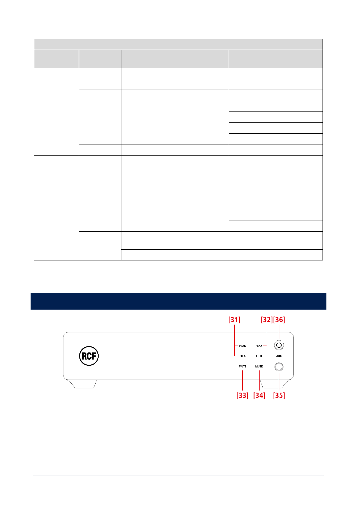
40
RMT B
IMPOSTAZIONE
AMPLIFICATORE
COMANDO FUNZIONE
MONO
VOLUME Agisce solamente su volume di OUT B
MUTE Agisce solamente su mute di OUT B
SELEZIONE
INGRESSO
Agisce solamente sulla selezione dell'input di
OUT B
ROUTING INGRESSI
IN1 MONO
IN2 MONO
EXT MONO
BAL IN
APPLICAZIONI
Singola macchina - 2 zone
STEREO /
BRIDGE
VOLUME Agisce solamente sul volume di BUS OUT 3
MUTE Agisce solamente su mute di BUS OUT 3
SELEZIONE
INGRESSO
Agisce solamente sulla selezione dell'input di
BUS OUT 3
ROUTING INGRESSI
IN1 MONO
IN2 MONO
EXT MONO
BAL IN
APPLICAZIONI
2 macchine - Sistema 2.1 (si usa solo RMT A
per satelliti e sub ed è necessario il cavallotto)
2 o più macchine - 2 zone 70V o bridge
DMA 162P: PANNELLO FRONTALE
[31] CH A / PEAK (due LED): CH A si accende quando è presente un segnale sul canale A. PEAK lampeggia quando il livello del
segnale del canale A raggiunge il punto di clipping, causando l’intervento del limitatore interno; se acceso fisso, il livello è eccessivo
e deve essere ridotto.
[32] CH B / PEAK (due LED): CH B si accende quando è presente un segnale sul canale B. PEAK lampeggia quando il livello del
segnale del canale B raggiunge il punto di clipping, causando l’intervento del limitatore interno; se acceso fisso, il livello è eccessivo
e deve essere ridotto.
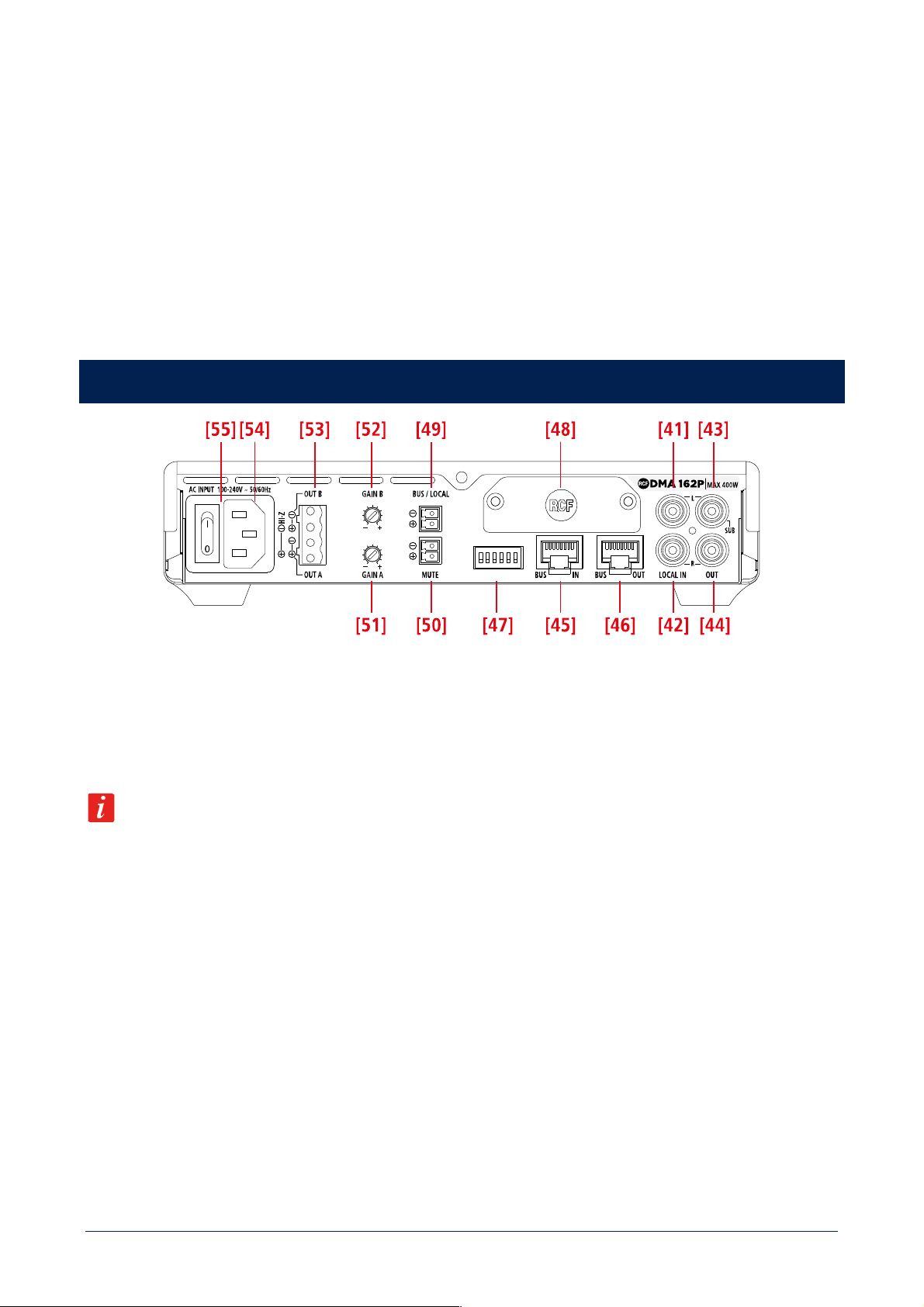
41
[33] CH A MUTE (LED): quando è acceso, l’uscita del canale A è disattivata.
[34] CH B MUTE (LED): quando è acceso, l’uscita del canale B è disattivata.
[35] Ingresso audio AUX (jack stereo TRS da 3,5 mm): se un connettore jack è inserito, l’ingresso LOCAL IN [41], [42] posteriore è
disabilitato; l’attivazione si effettua ponendo in cortocircuito i contatti dell’ingresso logico BUS / LOCAL [49].
[36] Tasto STAND-BY con LED: premere per attivare o mettere in “stand-by” l’amplificatore. Il LED si accende bianco quando
l’amplificatore è in funzione, rosso quando è in stand-by.
DMA 162P: PANNELLO POSTERIORE
[41] Ingresso audio LOCAL IN (canale sinistro): ingresso di linea sbilanciato con presa RCA, utile per il collegamento di una sorgente
musicale locale; l’attivazione si effettua ponendo in cortocircuito i contatti dell’ingresso logico BUS / LOCAL [49].
[42] Ingresso audio LOCAL IN (canale destro): ingresso di linea sbilanciato con presa RCA, utile per il collegamento di una sorgente
musicale locale; l’attivazione si effettua ponendo in cortocircuito i contatti dell’ingresso logico BUS / LOCAL [49].
Se un connettore jack e inserito nell’ingresso AUX [35] del pannello frontale, l’ingresso IN 1 [41], [42] sul retro e
momentaneamente disabilitato.
[43] Uscita audio OUT (canale sinistro) / SUB: uscita di linea sbilanciata con presa RCA. Può essere impostata per inviare una copia
del segnale audio presente all’uscita A o lo stesso segnale filtrato da un filtro passa-basso (80 Hz) utile per collegare un subwoofer
attivo.
[44] Uscita audio OUT (canale destro) / SUB: uscita di linea sbilanciata con presa RCA. Può essere impostata per inviare una copia
del segnale audio presente all’uscita B o lo stesso segnale filtrato da un filtro passa-basso (80 Hz) utile per collegare un subwoofer
attivo.
[45] Ingresso BUS IN (presa RJ45): si collega all’uscita BUS dell’amplificatore 82/162 o del precedente DMA[P].
[46] Uscita BUS OUT (presa RJ45): si collega all’ingresso BUS del successivo DMA[P].
[47] Selettori dip-switch (giù: off, su: ON).
Quando i contatti BUS / LOCAL
[49] sono aperti (audio dal BUS a 4 canali):
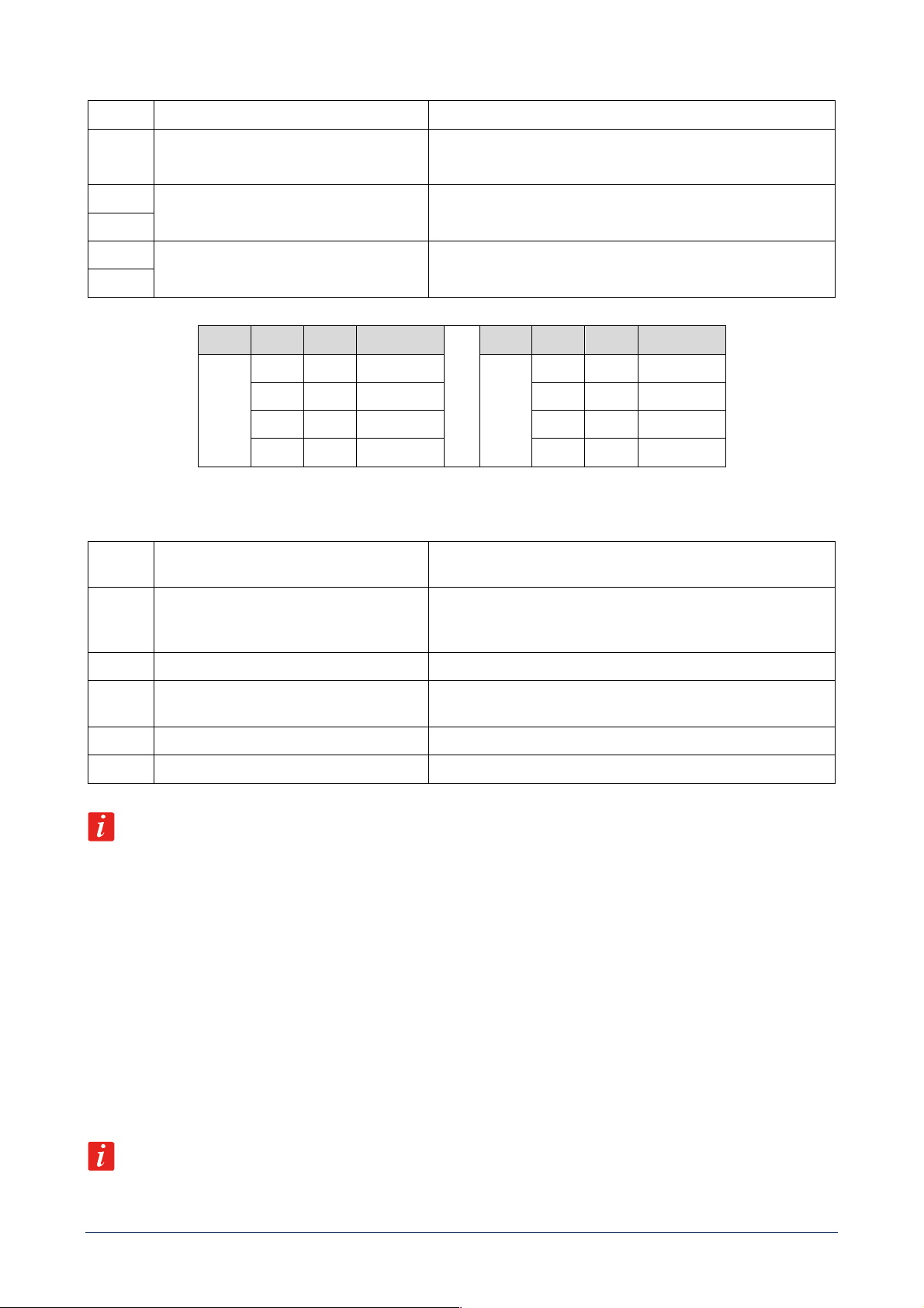
42
1
BRIDGE / MONO
Imposta modalità BRIDGE o MONO
2
SUB / AUX
Se impostato su SUB, sulle uscite posteriori OUT / SUB [43], [44] è
inserito un passa-basso a 80 Hz, utile per la connessione di
subwoofer attivi
3
CHANNEL SELECTION A
Selezione del canale da assegnare all’uscita A (vedere la tabella
successiva)
4
5
CHANNEL SELECTION B
Selezione del canale da assegnare all’uscita B (vedere la tabella
successiva)
6
OUT DIP 3 DIP 4 SEL. BUS CH
OUT DIP 5 DIP 6 SEL. BUS CH
A
Off Off 1
B
Off Off 1
Off ON 2 Off ON 2
ON Off 3 ON Off 3
ON ON 4 ON ON 4
Quando i contatti BUS / LOCAL [49] sono in cortocircuito (audio solo da LOCAL IN):
1
BASS ENANCHER OFF / ON
Se impostato su BASS ON, si enfatizzano le basse frequenze su tutte
le uscite
2
SUB / AUX
Se impostato su SUB, sulle uscite posteriori OUT / SUB [43], [44] è
inserito un passa-basso a 80 Hz, utile per la connessione di
subwoofer attivi
3
Not used
4
DUAL IN
Se impostato su ON, e BRIDGE e STEREO sono impostati su Off,
attiva una modalità con 2 segnali mono e volumi indipendenti.
5
BRIDGE
Se impostato su ON attiva la modalità BRIDGE.
6
STEREO / MONO
Se BRIDGE è impostato su Off, attiva le modalità STEREO o MONO.
L’ordine di priorità delle funzioni associate ai dip-switch è: BRIDGE > STEREO > DUAL IN > MONO.
[48] Pannello cieco da rimuovere durante l’installazione della scheda opzionale RDNET.
[49] BUS / LOCAL (morsettiera a vite rimovibile): ingresso logico per contatto pulito. Quando i suoi contatti sono aperti, l’amplificatore
DMA[P] riceve segnali audio dal BUS IN [45] (ed il suo ingresso locale LOCAL IN e disabilitato); quando i suoi contatti sono in
cortocircuito, l’amplificatore DMA[P] e direttamente collegato al solo ingresso locale LOCAL IN [41], [42].
[50] MUTE (morsettiera a vite estraibile): ingresso per contatto pulito per la messa in “mute” (quando cortocircuitato).
[51] GAIN A: ruotare il controllo in senso orario per aumentare il volume dell’uscita A od in senso antiorario per diminuirlo.
[52] GAIN B: ruotare il controllo in senso orario per aumentare il volume dell’uscita B od in senso antiorario per diminuirlo.
Quando la modalità STEREO o BRIDGE sono attivate, GAIN A agisce sia su OUT A sia su OUT B.
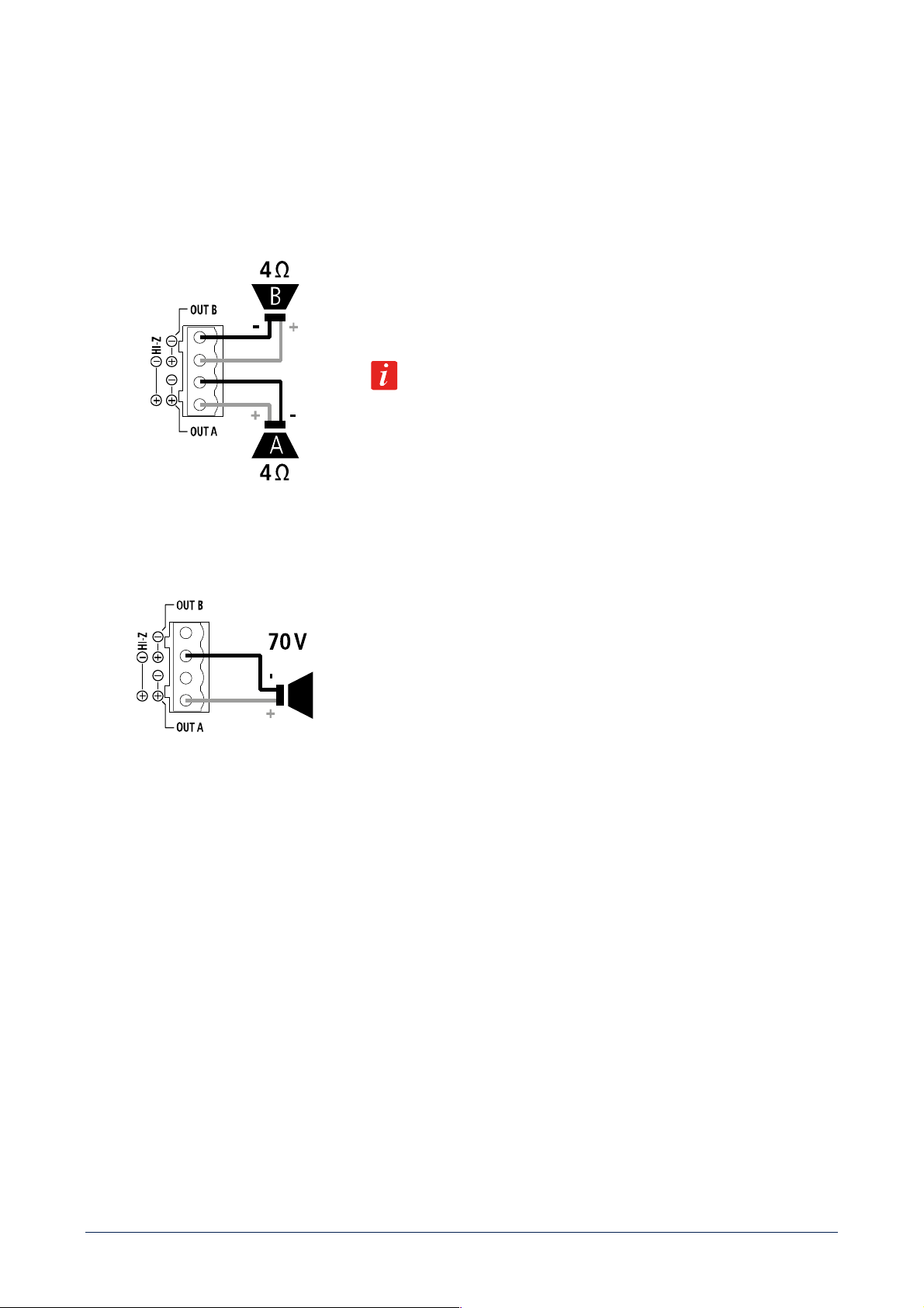
43
[53] USCITE ALTOPARLANTI
Le uscite per altoparlanti dell’amplificatore DMA consentono connessioni a bassa impedenza su due canali oppure una singola linea
da 70 V per diffusori acustici con trasformatore.
Connettore: EUROBLOCK (morsettiera a vite rimovibile).
DUE CANALI (A, B) COLLEGAMENTO A BASSA IMPEDENZA (4 Ω)
Collegare gli altoparlanti come mostrato in figura.
Impedenza minima del carico: 4 Ω per canale.
POTENZA EROGATA
2 x 160 W RMS su 4 Ω
Un'impedenza pari a 4 Ω consente di ottenere la massima potenza (80/160 W).
Un'impedenza più elevata porta a una riduzione della potenza erogata (ad es. 8
Ω: circa 40/80 W); un'impedenza inferiore a 4 Ω sovraccarica l’amplificatore.
SINGOLA LINEA 70 V
Collegare la linea per altoparlanti come mostrato in figura.
I due canali sono messi “a ponte” in modo da ottenere una singola linea a 70 V.
NON collegare gli altri due contatti.
Tutti i diffusori acustici dovranno avere un trasformatore con ingresso 70 V.
La potenza totale complessiva dei diffusori acustici non dovrà eccedere il valore
di 320 W.
[54] Ingresso per il cavo d’alimentazione. Collegare il cavo d’alimentazione solo ad una presa di corrente avente la messa a terra.
[55] Interruttore principale: premere per accendere (I) oppure spegnere (O) l’amplificatore.
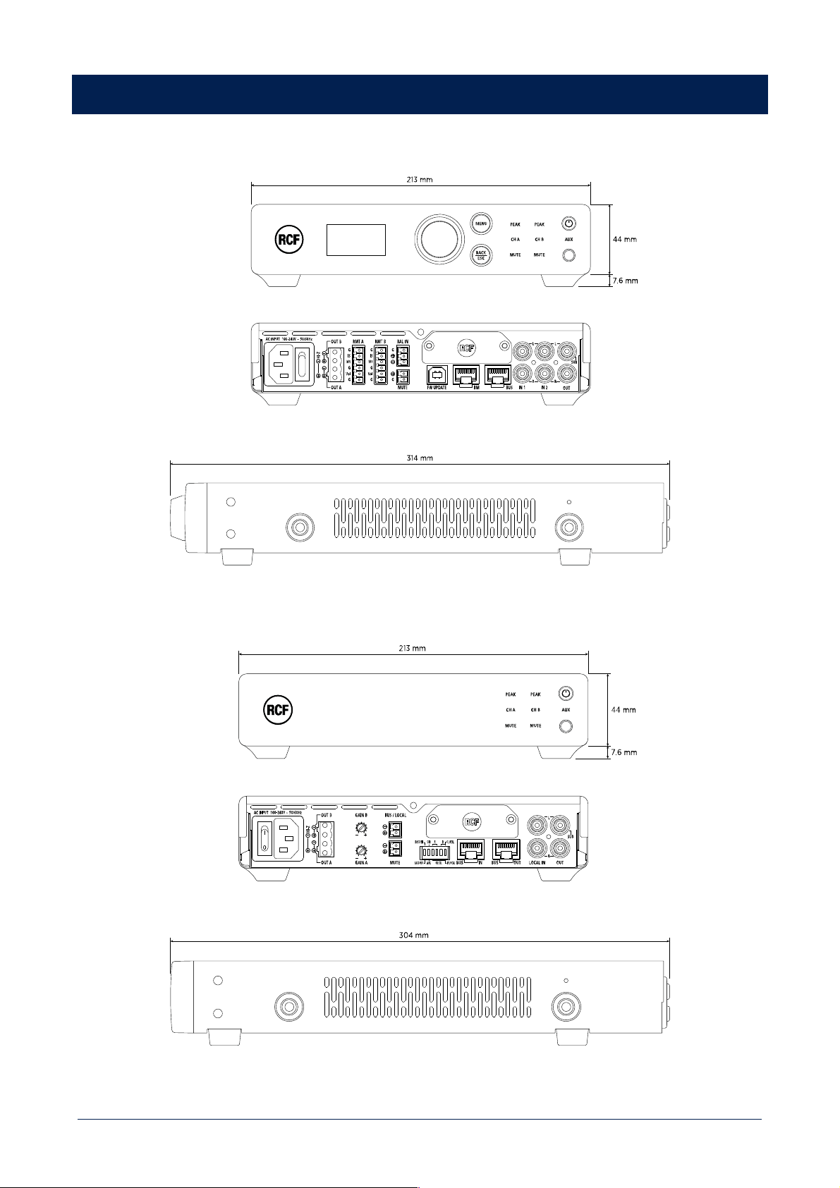
44
DIMENSIONS
DMA 82 / DMA 162
DMA 162P

45
SPECIFICATIONS
DMA 82 DMA 162 DMA 162P
Amplifier specifications
Amplifier Class: D D D
Number of channels: 2 2 2
Power output per channel (@ 4 ohm): 80 W RMS 160 W RMS 160 W RMS
Power output (bridged @ 4 ohm): 160 W RMS 320 W RMS 320 W RMS
Power output (Hi-Z): 160 W RMS 320 W RMS 320 W RMS
Frequency Response (-3dB): 20 Hz ÷ 20000 Hz 20 Hz ÷ 20000 Hz 20 Hz ÷ 20000 Hz
Signal/noise rate (”A” weighted) >93 dB >93 dB >93 dB
Distortion (THD+N) @ 1 kHz nominal power: <0.01 % <0.01 % <0.01 %
Input section
Total number of inputs: 5 5 6
Balanced: 2 2 4
Unbalanced: 3 3 2
Mono: 2 2 4
Stereo: 3 3 2
VOX: Yes Yes
Line inputs: 3 3 6
Line connectors: JACK, Picoflex, RCA JACK, Picoflex, RCA Picoflex, RCA, RJ45
Mic+Line inputs: 1 1
Mic+Line connectors: Euroblock Euroblock
Paging inputs: 1 1
Paging connectors: RJ45 RJ45
Paging command: Contact Contact
General Purpose Inputs (GPI): 1 1 2
Output section
Signal output number: 1 1 1
Signal output connectors: RCA RCA RCA
Power output connectors: Euroblock Euroblock Euroblock
Processing
DSP: Yes Yes Yes
EQ Filters: Yes Yes Yes
FIR: Yes Yes Yes
Compressors: Yes Yes Yes
Tone controls: Yes Yes Yes
High-pass filter: 80 Hz ÷ 200 Hz 80 Hz ÷ 200 Hz 80 Hz ÷ 200 Hz
Controls
Configuration: Front panel, PC Software Front panel, PC Software DIP switch, PC Software
Protocols for system integration: Proprietary Proprietary Proprietary
RDNet: Yes Yes Ready
Protections
Cooling: Forced Forced Forced
Short circuit: Yes Yes Yes
Thermal: Yes Yes Yes
DC: Yes Yes Yes
Fuses: Yes Yes Yes
VHF (Very High Frequencies): Yes Yes Yes

46
DMA 82 DMA 162 DMA 162P
Power requirement
Operating voltage: 90-240 V~ 50/60Hz 90-240 V~ 50/60Hz 90-240 V~ 50/60Hz
Power consumption: 200 W 400 W 400 W
Standard compliance
CE marking: Yes Yes Yes
Physical specifications
Cabinet/Case Material: Metal Metal Metal
Color: Black Black Black
Rack mounting: 1/2 19", 1U , Optional rack
mounting accessory required
1/2 19", 1U , Optional rack
mounting accessory required
1/2 19", 1U , Optional rack
mounting accessory required
Size
Height: 44 mm / 1.73 inches 44 mm / 1.73 inches 44 mm / 1.73 inches
Width: 213 mm / 8.39 inches 213 mm / 8.39 inches 213 mm / 8.39 inches
Depth: 314 mm / 12.36 inches 314 mm / 12.36 inches 304 mm / 11.97 inches
Weight: 1.7 kg / 3.75 lbs 1.7 kg / 3.75 lbs 1.65 kg / 3.64 lbs
Package Height: 106 mm / 4.17 inches 106 mm / 4.17 inches 106 mm / 4.17 inches
Package Width: 360 mm / 14.17 inches 360 mm / 14.17 inches 360 mm / 14.17 inches
Package Depth: 381 mm / 15 inches 381 mm / 15 inches 381 mm / 15 inches
Package Weight: 2.7 kg / 5.95 lbs 2.7 kg / 5.95 lbs 2.65 kg / 5.84 lbs

47

RCF S.p.A. Via Raffaello Sanzio, 13 - 42124 Reggio Emilia – Italy 10307649 D
Tel +39 0522 274 411 - Fax +39 0522 232 428 - e-mail: [email protected] - www.rcf.it