
USER MANUAL
MANUALE D’USO
UP 8501
UP 8502
UP 8504
- AMPLIFIERS
- AMPLIFICATORI


TABLE OF CONTENTS
INDICE
ENGLISH
SAFETY PRECAUTIONS
NOTES ABOUT AUDIO SIGNAL CABLES
DESCRIPTION
MOUNTING INTO 19” RACK CABINETS
FRONT PANEL
REAR PANEL
REMOTE VOLUME CONTROL
LOUDSPEAKER CONNECTION
POWER SUPPLY VOLTAGE CHANGE
SPECIFICATIONS
ITALIANO
AVVERTENZE PER LA SICUREZZA
NOTA SUI CAVI PER SEGNALI AUDIO
DESCRIZIONE
INSTALLAZIONE NEI RACK DA 19”
PANNELLO FRONTALE
PANNELLO POSTERIORE
REGOLAZIONE REMOTA DEL VOLUME
COLLEGAMENTO DEI DIFFUSORI ACUSTICI
CAMBIO TENSIONE DI FUNZIONAMENTO DELL’APPARECCHIO
DATI TECNICI
4
5
6
6
7
8
11
12
13
14
15
16
17
17
18
19
23
24
25
26

4
ENGLISH
IMPORTANT
Before connecting and using this product, please read this instruction manual carefully and
keep it on hand for future reference.
The manual is to be considered an integral part of this product and must accompany it
when it changes ownership as a reference for correct installation and use as well as for the
safety precautions.
RCF S.p.A. will not assume any responsibility for the incorrect installation and / or use of
this product.
WARNING: To prevent the risk of fire or electric shock, never expose this product to rain
or humidity.
SAFETY PRECAUTIONS
1. All the precautions, in particular the safety ones, must be read with special attention, as
they provide important information.
2.1 PRIMARY POWER SUPPLY FROM MAINS
- The mains voltage is sufficiently high to involve a risk of electrocution: never install or
connect this product when its power cable is plugged in.
- Before powering up, make sure that all the connections have been made correctly and
the voltage of your mains corresponds to the voltage shown on the rating plate on the
unit, if not, please contact your RCF dealer.
- The metallic parts of the unit are earthed by means of the power cable.
- An apparatus with CLASS I construction shall be connected to a mains socket outlet
with a protective earthing connection.
- Protect the power cable from damage. Make sure it is positioned in a way that it cannot
be stepped on or crushed by objects.
- To prevent the risk of electric shock, never open this product: there are no parts inside
that the user needs to access.
2.2 SECONDARY (/ EMERGENCY) POWER SUPPLY THROUGH BATTERIES
- The apparatus operating voltage is 48 V dc (therefore, it is necessary to connect in series
several batteries having a lower nominal voltage, example: 4 x 12 V, 2 x 24 V).
- Always use rechargeable batteries, which need to be chosen according to the maximum
possible load.
- Verify the polarity of batteries is correct.
- Do NOT short-circuit batteries (i.e. connecting the 2 opposite poles together with
metallic wires).
- Throw empty batteries away according to your country laws about ecology and
environment protection.
3. Make sure that no objects or liquids can get into this product, as this may cause a short
circuit. This apparatus shall not be exposed to dripping or splashing. No objects filled with
liquid, such as vases, shall be placed on this apparatus. No naked sources (such as lighted
candles) should be placed on this apparatus.
4. Never attempt to carry out any operations, modifications or repairs that are not expressly
described in this manual.
Contact your authorized service centre or qualified personnel should any of the following occur:
- The product does not function (or functions in an anomalous way).
- The power supply cable has been damaged.
- Objects or liquids have got in the unit.
- The product has been subject to a heavy impact.
5. If this product is not used for a long period, disconnect the power cable (and or batteries).
6. If this product begins emitting any strange odours or smoke, switch it off immediately
and disconnect the power supply cable (and / or batteries).
IMPORTANT
WARNING
SAFETY
PRECAUTIONS

5
ENGLISH
7. The terminals marked with the symbol are HAZARDOUS LIVE and their connection
is to be made by an INSTRUCTED PERSON or the use of ready-made cables is required.
8. Do not connect this product to any equipment or accessories not foreseen.
For suspended installation, only use the dedicated anchoring points and do not try to hang
this product by using elements that are unsuitable or not specific for this purpose.
Also check the suitability of the support surface to which the product is anchored (wall,
ceiling, structure, etc.), and the components used for attachment (screw anchors, screws,
brackets not supplied by RCF etc.), which must guarantee the security of the system /
installation over time, also considering, for example, the mechanical vibrations normally
generated by transducers.
To prevent the risk of falling equipment, do not stack multiple units of this product unless
this possibility is specified in the user manual.
9. RCF S.p.A. strongly recommends this product is only installed by professional
qualified installers (or specialised firms) who can ensure correct installation
and certify it according to the regulations in force.
The entire audio system must comply with the current standards and
regulations regarding electrical systems.
10. Supports and trolleys
The equipment should be only used on trolleys or supports, where necessary, that are
recommended by the manufacturer. The equipment / support / trolley assembly must be
moved with extreme caution. Sudden stops, excessive pushing force and uneven floors may
cause the assembly to overturn.
11. There are numerous mechanical and electrical factors to be considered when installing
a professional audio system (in addition to those which are strictly acoustic, such as sound
pressure, angles of coverage, frequency response, etc.).
12. Hearing loss
Exposure to high sound levels can cause permanent hearing loss. The acoustic pressure
level that leads to hearing loss is different from person to person and depends on the
duration of exposure. To prevent potentially dangerous exposure to high levels of acoustic
pressure, anyone who is exposed to these levels should use adequate protection devices.
When a transducer capable of producing high sound levels is being used, it is therefore
necessary to wear ear plugs or protective earphones.
See the technical specifications in loudspeaker instruction manuals to know their maximum
sound pressure levels.
13. Do not obstruct the ventilation grilles of the unit. Situate this product far from any heat
sources and always ensure adequate air circulation around the ventilation grilles.
14. Do not overload this product for a long time.
15. Never force the control elements (keys, knobs, etc. ).
16. Do not use solvents, alcohol, benzene or other volatile substances for cleaning the
external parts of this product.
Use a dry cloth.
To prevent the occurrence of noise on microphone / line signal cables, use screened cables
only and avoid putting them close to:
- Equipment that produces high-intensity electromagnetic fields (for example, high power
transformers)
- Mains cables
- Loudspeaker lines.
IMPORTANT NOTES
NOTES ABOUT AUDIO SIGNAL CABLES

6
ENGLISH
RCF S.P.A. THANKS YOU FOR PURCHASING THIS PRODUCT, WHICH HAS BEEN
DESIGNED TO GUARANTEE RELIABILITY AND HIGH PERFORMANCES.
DESCRIPTION
The UP 8500 amplifier series includes 3 similar models having different channel number
and maximum output power per channel:
- UP 8501 1 channel, max. power: 500 W
- UP 8502 2 channels, max. power: 250 W per channel
- UP 8504 4 channels, max. power: 125 W per channel.
Each channel has 3 audio inputs (all ‘line’ level):
- INPUT 1 ‘LINE’ balanced input (for signals coming from preamplifiers, active
paging microphones, message players, etc.).
- INPUT 2 ‘LINE’ balanced input (for signals coming from preamplifiers, active
paging microphones). It can be used for unbalanced stereo signals
(from CD – MP3 players, tuners, etc.).
- IN TEST Unbalanced input for channel test signals.
INPUT 1 is open when its priority command is activated only.
INPUT 2 is disabled when input 1 priority is in progress.
TEST IN input allows to use a test signal to verify the proper channel operation.
TEST IN input is open when its priority command is activated only (INPUT 1 and
INPUT 2 are disabled when the priority is in progress).
Channel outputs are 70 V – 100 V constant voltage lines (for loudspeakers having
matching transformers).
In addition to the connection to the mains, the amplifier can also be powered by batteries
(voltage: 48 V dc), in order to ensure its proper operation even when the mains supply is
temporarily unavailable.
Front panel LEDs indicate the device state (on – stand-by), power supplies, protections
and audio signal levels.
Fix each amplifier on the 19” rack cabinet front side through 4 screws.
UP 8500 series amplifiers have forced ventilation controlled by a thermostat and can be
stacked without spaces or ventilation panels.
Air ventilation is horizontally, so it is necessary to keep open the lateral sides.
MOUNTING INTO 19” RACK CABINETS
7
ENGLISH
FRONT
PANEL
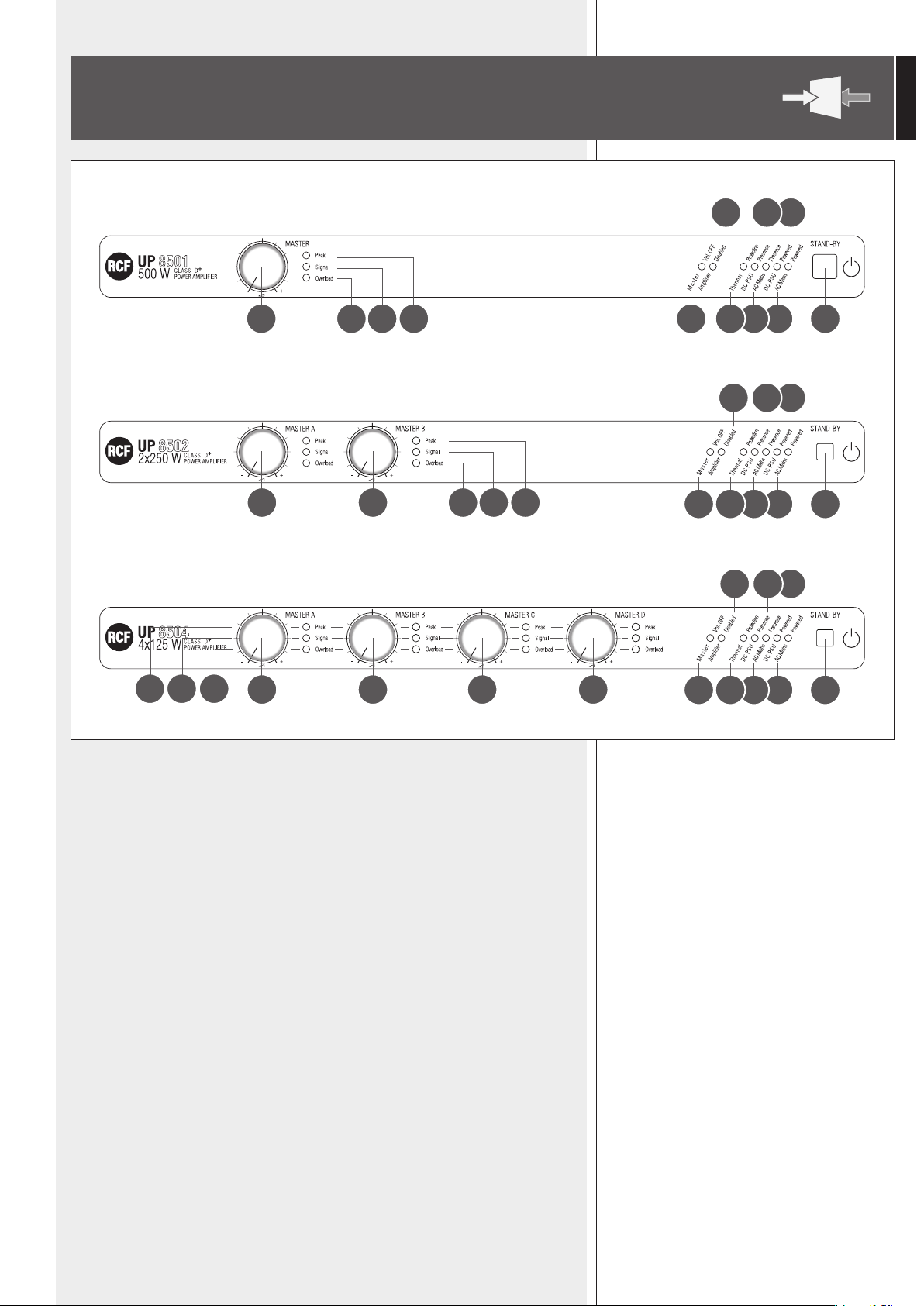
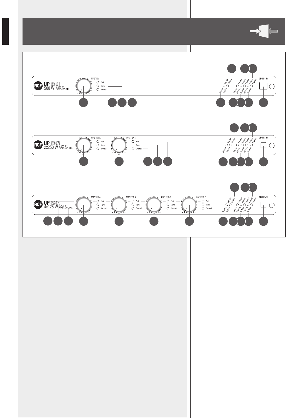
1 STAND-BY switch.
The STAND-BY switch is disabled (the amplifier stays on) if the secondary 48 V dc power
supply is present (batteries connected to the respective input i).
2 AC Mains Powered LED: (when lit) the amplifier is operating through the mains
power supply (115 - 230 V ac).
3 DC PSU Powered LED: (when lit) the amplifier is operating through batteries (48 V dc).
4 AC Mains Presence LED: (when lit) the mains power supply (115 - 230 V ac) is detected.
5 DC PSU Presence LED: (when lit) the 48 V dc power supply (by batteries) is detected.
6
Thermal
Protection LED: (when lit) the thermal protection is activated (the amplifier is muted).
7 Amplifier Disabled LED: (when lit) the amplifier has been disabled by the ‘Amplifier
Disable’ command t.
8 Master Vol. OFF LED: (when lit) all the MASTER volume controls } are disabled
(volumes depend on remote controls, see ‘Rem Vol’ r).
9 Signal LED: (when lit) the signal level is equal or higher than –20 dB.
UP 8502 and UP 8504: each LED indicates the signal level on the respective channel.
UP 8501 (1 x 500 W)
12 2 146811 9 10
357
UP 8502 (2 x 250 W)
12b12a
2 1468
11 9 10
357
UP 8504 (4 x 125 W)
2 1468
11910
357
12b 12d12a 12c
8
ENGLISH
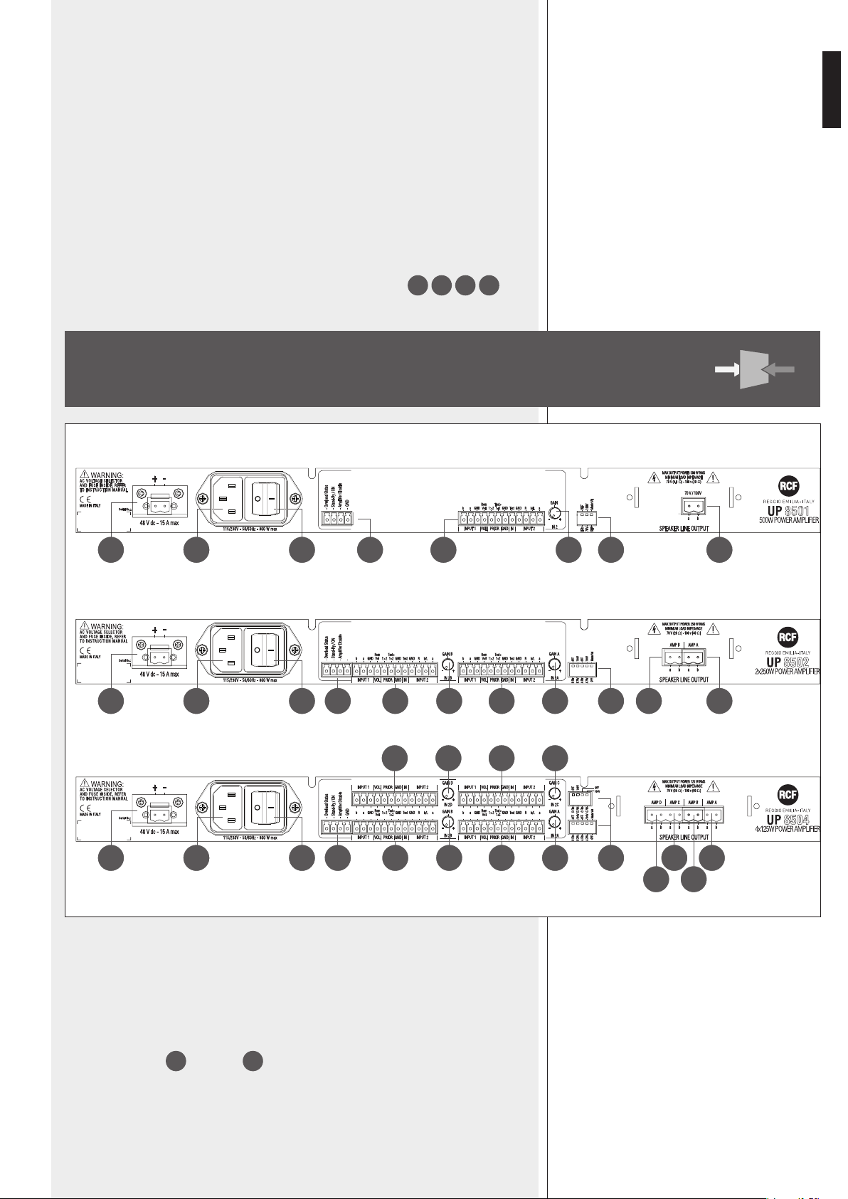
REAR PANEL
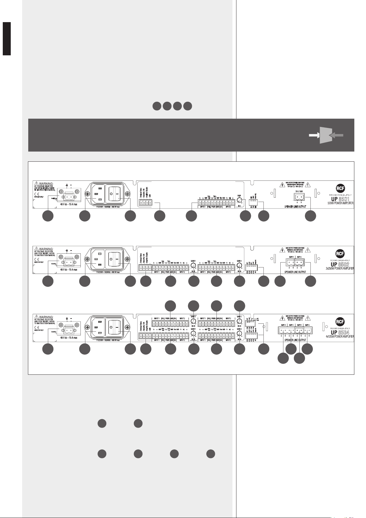
q SPEAKER LINE OUTPUT
UP 8501: amplifier output to connect the 70 – 100 V constant voltage line for
loudspeakers (which need matching transformers). Max. output power: 500 W.
UP 8502: 2 amplifier outputs (
13a
: A channel,
13b
: B channel) to connect two
70 – 100 V constant voltage lines for loudspeakers (which need matching transformers).
Max. output power: 250 W per each channel.
UP 8504: 4 amplifier outputs (
13a
: A channel,
13b
: B channel,
13c
: C channel,
13d
: D
channel) to connect four 70 – 100 V constant voltage lines for loudspeakers (which need
matching transformers). Max. output power: 125 W per each channel.
Read the ‘LoudspeakeR connection’ manuaL section.
P Peak LED: (when lit) signal level (0 dB, peak) that allows to get the maximum
deliverable power of the amplifier and is the limiter threshold.
UP 8502 and UP 8504: each LED indicates the maximum signal level on the
respective channel. Occasional flashing is normal, but it is advisable to turn the
respective MASTER volume down when a ‘Peak’ LED is steady lit.
{ Overload LED: (when lit) the overload protection is activated on the
respective channel (no signal is sent to the relative output).
} MASTER volume control
UP 8502 and UP 8504: volume control of each channel
12a
12b
12c
12d
.
UP 8502
13a13b1415a15b17 16b 16a181920
UP 8501
13141517181920
UP 8504
1415a
15c16c15d16d
13d 13b
13c 13a15b17 16b 16a181920
16
9
ENGLISH
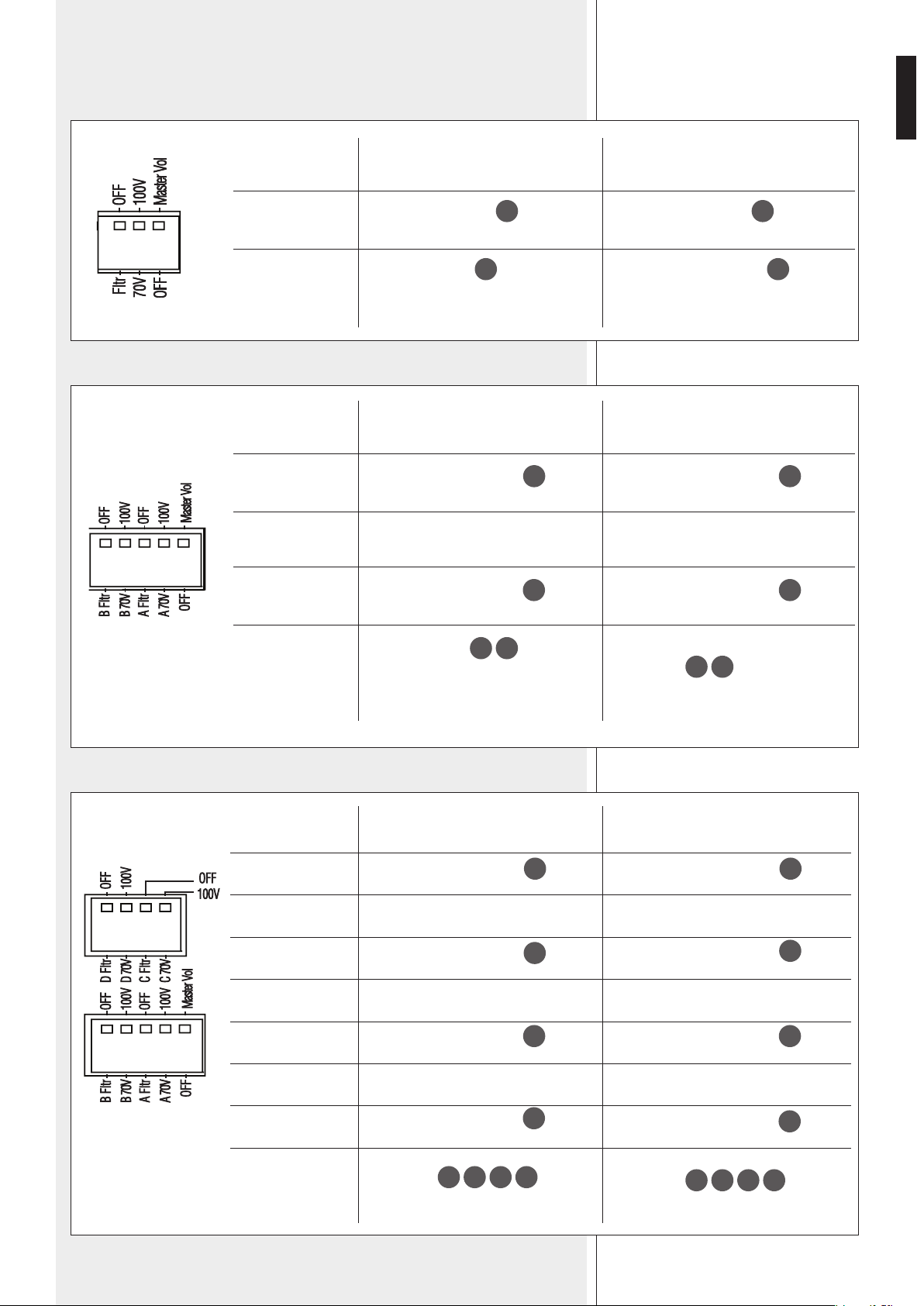
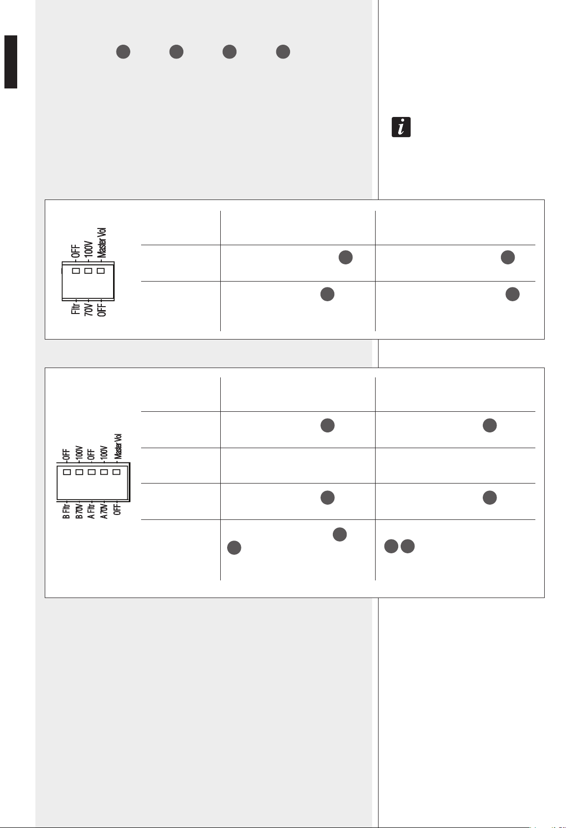
w Dip-switches
UP 8501
UP 8502
UP 8504
Fltr – OFF
70V – 100V
OFF – Master Vol
Fltr: the band-pass filter is inserted
(200 Hz ÷ 8 kHz).
70V: Amplifier output
13
for
loudspeakers is set to 70 V.
OFF: the MASTER
12
volume control
is disabled (the volume depends on the
remote control).
OFF: the band-pass filter is not inserted.
100V: Amplifier output
13
for
loudspeakers is set to 100 V.
Master Vol: the MASTER
12
volume
control is enabled.
B Fltr – OFF
B 70V – 100V
A Fltr – OFF
A 70V – 100V
OFF – Master Vol
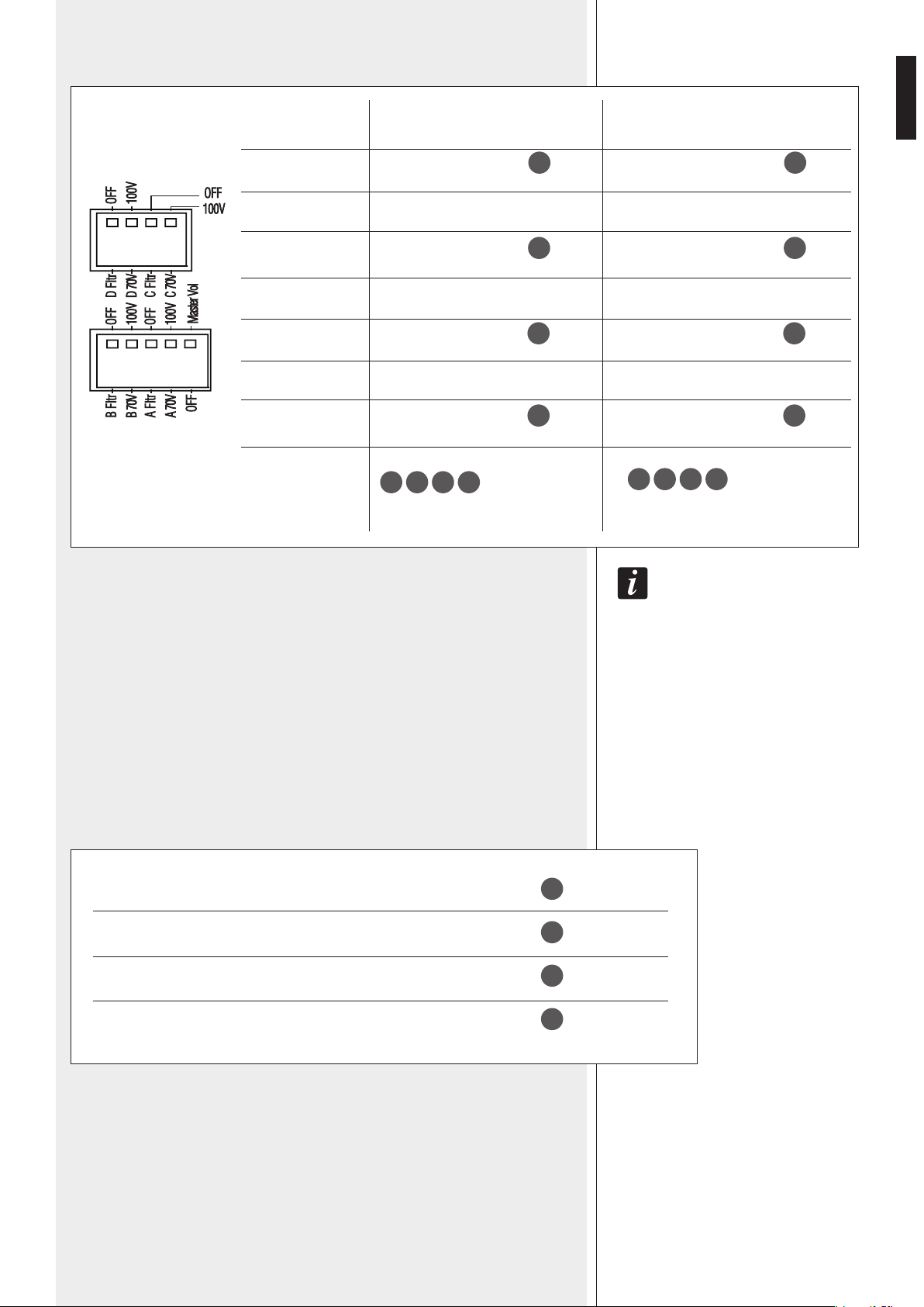
D Fltr – OFF
D 70V – 100V
C Fltr – OFF
C 70V – 100V
B Fltr – OFF
B 70V – 100V
A Fltr – OFF
A 70V – 100V
OFF – Master Vol
B Fltr: the band-pass filter of the B
channel is inserted.
70V: the B channel output
13b
for
loudspeakers is set to 70 V.
A Fltr: the band-pass filter of the A
channel is inserted.
70V: the A channel output
13a
for
loudspeakers is set to 70 V.
OFF: all MASTER
12a
12b
volume
controls are disabled
(all volumes depend on the remote
controls).
D Fltr: the band-pass filter of the D
channel is inserted.
70V: the D channel output
13d
for
loudspeakers is set to 70 V.
C Fltr: the band-pass filter of the C
channel is inserted.
70V: the C channel output
13c
for
loudspeakers is set to 70 V.
B Fltr: the band-pass filter of the B
channel is inserted.
70V: the B channel output
13b
for
loudspeakers is set to 70 V.
A Fltr: the band-pass filter of the A
channel is inserted.
70V: the A channel output
13a
for
loudspeakers is set to 70 V.
OFF:
all MASTER
12a
12b
12c
12d
volume
controls are disabled (all volumes depend
on the remote controls).
OFF: the band-pass filter of the B
channel is not inserted.
100V: the B channel output
13b
for
loudspeakers is set to 100 V.
OFF: the band-pass filter of the A
channel is not inserted.
100V: the A channel output
13a
for
loudspeakers is set to 100 V.
Master Vol:
all MASTER
12a
12b
volume controls
are enabled.
OFF: the band-pass filter of the D
channel is not inserted.
100V: the D channel output
13d
for
loudspeakers is set to 100 V.
OFF: the band-pass filter of the C
channel is not inserted.
100V: the C channel output
13c
for
loudspeakers is set to 100 V.
OFF: the band-pass filter of the B
channel is not inserted.
100V: the B channel output
13b
for
loudspeakers is set to 100 V.
OFF: the band-pass filter of the A
channel is not inserted.
100V: the A channel output
13a
for
loudspeakers is set to 100 V.
Master Vol:
all MASTER
12a
12b
12c
12d
volume
controls are enabled.
10
ENGLISH
the inseRtion of band-pass fiLteRs (one peR each channeL, passband: 200 hz ÷ 8 khz) is advisabLe in
some cases, foR instance:
- When hoRn LoudspeakeRs aRe used.
- to get a betteR speech inteLLigibiLity in haLLs / Rooms having a Long ReveRb.
- to cut possibLe noises on LoW / high fRequencies.
if it is Requested high fideLity of music, it WiLL be necessaRy to disabLe band-pass fiLteRs.
e IN2 GAIN: control to adjust the gain of the audio INPUT 2 r.
Turn it either clockwise to increase its gain or counterclockwise to reduce it.
UP 8502 and UP 8504: each IN2 GAIN control adjusts the gain of the respective channel.
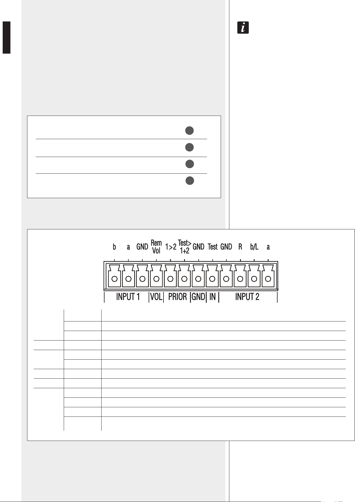
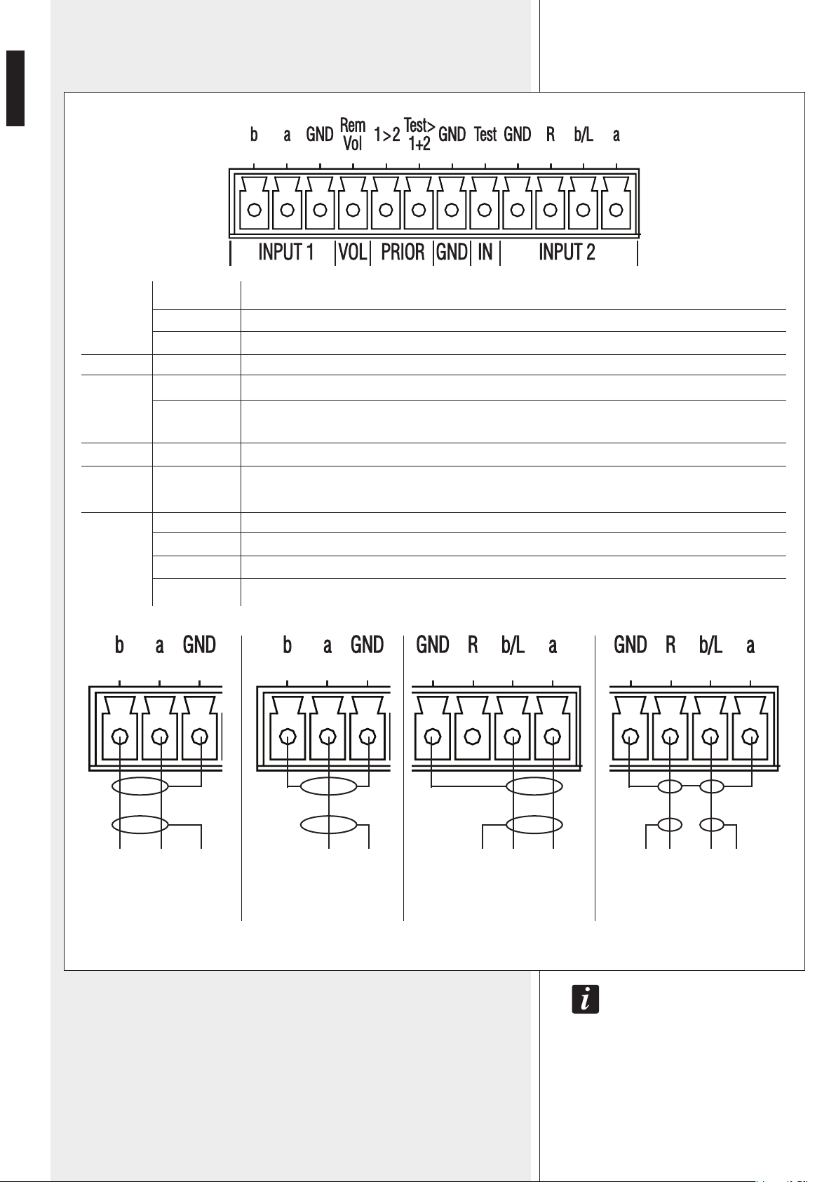
r Removable terminal strips (UP 8502 and UP 8504: a terminal strip per each channel)
IN2A GAIN A
IN2B GAIN B
IN2C GAIN C
IN2D GAIN D
Gain control of the A channel audio INPUT 2
16a
Gain control of the B channel audio INPUT 2
16b
Gain control of the C channel audio INPUT 2
16c
Gain control of the D channel audio INPUT 2
16d
b
a
GND
Rem Vol
1 > 2
Test > 1 + 2
GND
Test
GND
R
b / L
a
Audio input 1, ‘b’ terminal
Audio input 1, ‘a’ terminal
Audio input 1, ground
Contact for the volume remote control
This contact needs to be linked to ground (GND – GND) to open INPUT 1 (INPUT 2 is muted).
This contact needs to be linked to ground (GND – GND) to open the TEST input (bot INPUT 1 and 2 are muted).
Common ground for PRIOR contacts
Test signal input. Link it to the ground (through a wire) when not used, as this input is always open.
Audio input 2, ground
Audio input 2, stereo signal right channel
Audio input 2, either ‘b’ terminal or stereo signal left channel
Audio input 2, ‘a’ terminal
INPUT 1
VOL
PRIOR
GND
IN
INPUT 2
11
ENGLISH
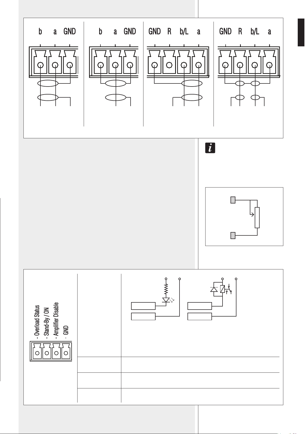
both channeLs (Left and Right, of a steReo audio signaL connected to the input 2) aRe mixed in
oRdeR to get a mono signaL.
INPUT 1 balanced
signal connection
INPUT 1 unbalanced
signal connection
INPUT 2 balanced signal
connection
INPUT 2 (unbalanced)
stereo signal connection
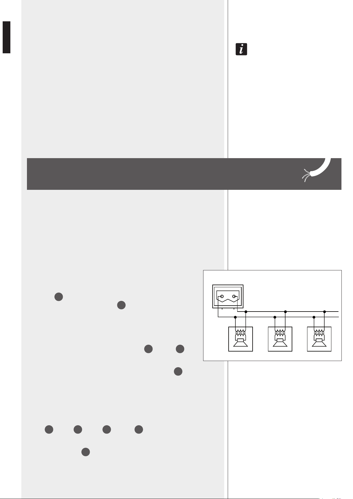
REMOTE VOLUME CONTROL
It is necessary to set the 'Master Vol' dip-switch w to OFF and insert a potentiometer
between the 'Rem Vol' and 'GND – GND' (ground) contacts.
Suggested potentiometer: 10 kΩ, inverse logarithmic curve.
IMPORTANT: If the ‘Master Vol’ dip-switch is set to OFF and one or more
remote control potentiometers are not foreseen, it is necessary to short-
circuit the respective contacts to ground (through a wire) to get the
maximum volume, otherwise the relevant channels are muted.
GND
+-
GND
+
GND
+-
Rem
Vol
GND
10 kΩ
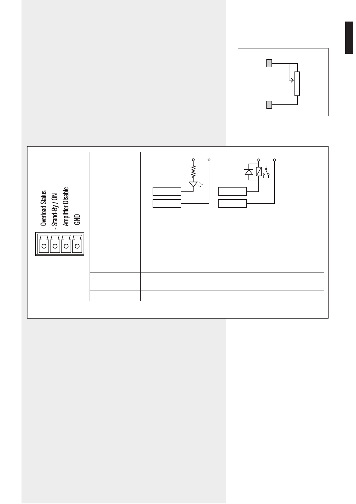
Overload Status
Stand-By / ON
Amplifier Disable
GND
Amplifier overload indication through (for example) either a LED (A picture) or a
relay (B picture).
‘Open collector’ circuit.
Max. voltage: 40 V dc
Max. current: 50 mA
Command linked in parallel to the front panel POWER 1 switch.
When linked to the ground (GND) contact, the amplifier is remotely turned on.
When linked to the ground (GND) contact: the amplifier is disabled in order to
save energy or select zones.
Ground common contact (for the previous three)
‘OPEN COLLECTOR’
max. 40 V
max. 50 mA
Overload Status Overload Status
GND GND
A B
+ V dc - + V dc -
Audio input 1, ‘b’ terminal
Audio input 1, ‘a’ terminal
Audio input 1, ground
Contact for the volume remote control
When this contact is linked to ground (GND – GND), the INPUT 1 has priority (INPUT 2 is muted)
When this contact is linked to ground (GND – GND), the ‘IN – Test’ input has priority (both INPUT 1 and 2 are muted)
Common ground for PRIOR contacts
Test signal input. Link it to the ground (through a wire) when not used, as this input is always open.
Audio input 2, ground
Audio input 2, stereo signal right channel
Audio input 2, either ‘b’ terminal or stereo signal left channel
Audio input 2, ‘a’ terminal
GNDGND LR
REMOTE VOLUME CONTROL
t Removable screw terminals
12
ENGLISH
y Main power switch
I = ON O = OFF
the main poWeR sWitch does not affect the poWeR suppLy by batteRies (48 v dc).
u Connector for the power cable
Before powering up, make sure that all the connections have been made correctly and
the voltage of your mains corresponds to the voltage shown on the rating plate on the
unit.
The voltage selector and the fuse are inside the amplifier.
Refer to the respective manual section.
i Input for the secondary 48 V dc power supply (batteries) necessary to ensure the
amplifier operation even if the mains supply is temporarily unavailable.
Make sure the connection polarity + / – is correct and use a cable having wires with a
suitable section (suggested: 4 mm²) for the max. current (15 A).
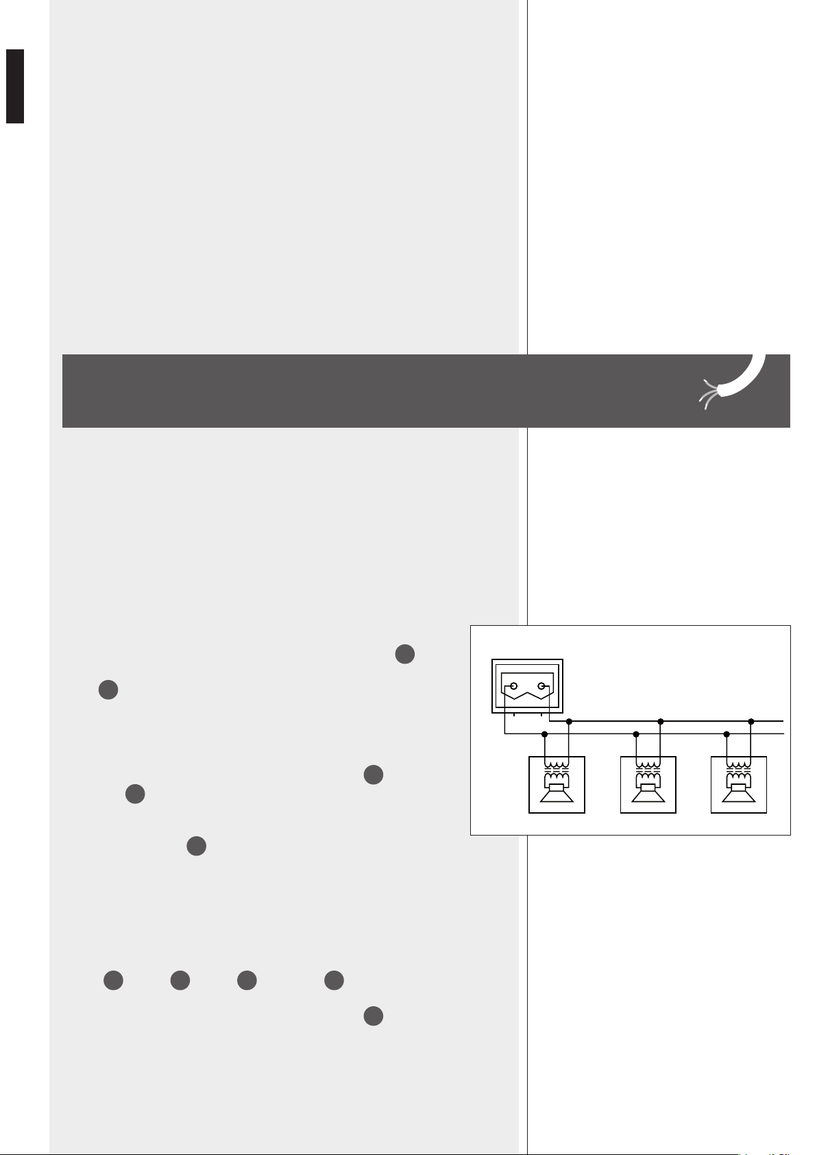
Connect all loudspeaker respecting the phase.
Every loudspeaker shall have a matching transformer, which input is suitable for the line
voltage (70 / 100 V).
Make sure loudspeaker lines are not shorted before turning the amplifier on.
Check periodically for possible ground leakage on loudspeaker lines to avoid amplifier
failure.
If necessary, intervene to re-establish line insulation.
UP 8501
After setting the amplifier output voltage through the 70V – 100V
14
dip-
switch, connect the positive wire of the loudspeaker line to the amplifier
output
13
‘a’ contact and the negative wire to the ‘b’ contact.
The total power of all connected loudspeakers shall not exceed the amplifier
nominal power (500 W).
UP 8502
This model has 2 independent outputs (2 channels): AMP A
13a
and AMP B
13b
.
Set the voltage of both outputs through the A 70V – 100V (AMP A) and
B 70V – 100V (AMP B)
14
dip-switches before connecting the
loudspeaker lines.
The total power of all connected loudspeakers of a single channel (considering only 1 of
the 2 available outputs) shall not exceed 250 W.
See the UP 8501 model for loudspeaker connection.
UP 8504
This model has 4 independent outputs (4 channels):
AMP A
13a
, AMP B
13b
, AMP C
13c
and AMP D
13d
.
Set the voltage of the 4 outputs through the A 70V – 100V (AMP A), B 70V – 100V
(AMP B), C 70V – 100V (AMP C), D 70V – 100V (AMP D)
14
dip-switches before
connecting the loudspeaker lines.
The total power of all connected loudspeakers of a single channel (considering only 1 of
the 4 available outputs) shall not exceed 125 W.
See the UP 8501 model for loudspeaker connection.
LOUDSPEAKER CONNECTION
70/100 V
70/100 V 70/100 V 70/100 V0 0 0
a b
13
ENGLISH
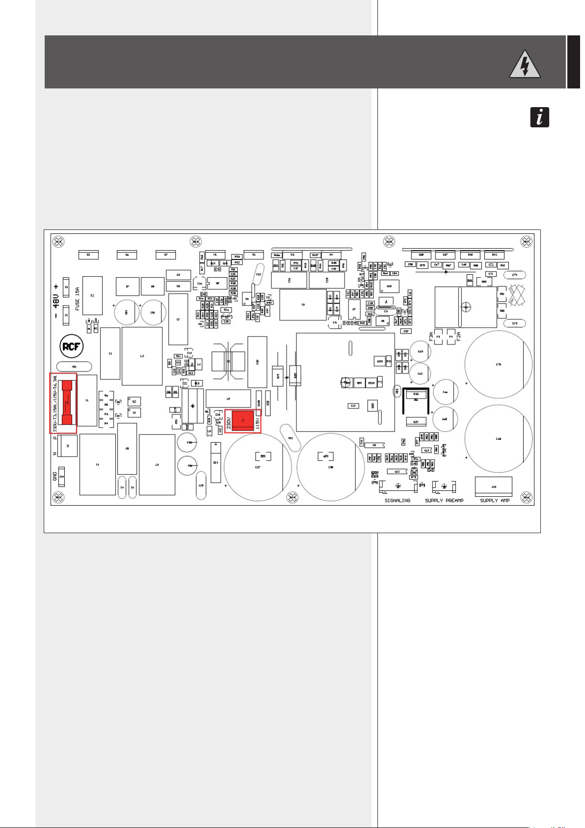
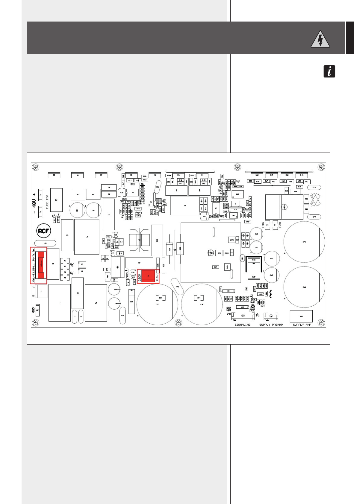
IMPORTANT: THIS MANUAL SECTION CONCERNS QUALIFIED PERSONNEL ONLY.
THE FOLLOWING INSTRUCTIONS ARE TO BE IGNORED BY THE USER.
Make sure the device is not connected to the mains (unplug the power cord).
Remove the lid.
The 230 V – 115 V voltage selector (‘J4’) is on the power supply printed circuit board (in its
centre). Change (if necessary) the voltage by moving ‘J4’ to the value corresponding to the
mains (either 230 V or 115 V), as according to the printed circuit board silk screen.
Make sure the F1 fuse (on the left in the power supply printed circuit board figure) is the
proper one for the operating voltage, before connecting the amplifier to the mains:
- 230 V – T3.15AL (250 V)
- 115 V – T6.3AL (250 V).
POWER SUPPLY VOLTAGE CHANGE
IMPORTANT
POWER SUPPLY PRINTED CIRCUIT BOARD
14
ENGLISH
SPECIFICATIONS
No. channels x output power (RMS)
Frequency response ±3 dB
Band-pass filter (12 dB / oct)
THD and noise (at max. power)
Signal / noise ratio (IEC-A)
Channel crosstalk
INPUT 1 sensitivity
INPUT 2 sensitivity
IN TEST sensitivity
Input impedance
Minimum load impedance of each 70 V line
Minimum load impedance of each 100 V line
Over signal limiter
Amplifier protections
Power supply protection
Operating voltage
Power consumption, AC stand-by
Power consumption, disabled amp.
Power consumption, no input signal
Power consumption, musical signal
Power consumption, max. output power
Power consumption, max. overload
Operating temperature
Storage temperature
Dimensions (w, h, d)
Net weight
1 x 500 W 2 x 250 W 4 x 125 W
40 Hz ÷ 16 kHz
200 Hz ÷ 8 kHz (passband)
max. 0.3%
86 dB
– 70 dB 60 dB
0 dBu (775 mV, max. 7 V)
0 ÷ –20 dBu (775 ÷ 78 mV, max. 7 V)
0 dBu (775 mV)
10 kΩ
10 Ω 20 Ω 40 Ω
20 Ω 40 Ω 80 Ω
20 dB
overload, thermal
fuse
Mains: 115 – 230V ac ±10%, 50 – 60 Hz (internal voltage selector)
Batteries: 48 V dc ±10%
3 W
13 W 15 W 20 W
25 W 36 W 50 W
160 W
650 W
800 W
0 ÷ 55 °C (32 ÷ 131 °F), rel. humidity: max. 90%
–10 ÷ 70 °C (14 ÷ 158 °F)
482 mm, 44 mm, 375 mm (one 19” rack unit)
5.1 kg 5.3 kg 5.5 kg
UP 8501 UP 8502 UP 8504

15
ITALIANO
IMPORTANTE
ATTENZIONE
AVVERTENZE PER
LA SICUREZZA
IMPORTANTE
Prima di collegare ed utilizzare questo prodotto, leggere attentamente le istruzioni
contenute in questo manuale, il quale è da conservare per riferimenti futuri.
Il presente manuale costituisce parte integrante del prodotto e deve accompagnare
quest’ultimo anche nei passaggi di proprietà, per permettere al nuovo proprietario
di conoscere le modalità d’installazione e d’utilizzo e le avvertenze per la sicurezza.
L’installazione e l’utilizzo errati del prodotto esimono la RCF S.p.A. da ogni responsabilità.
ATTENZIONE: Per prevenire i rischi di fiamme o scosse elettriche, non esporre mai questo
prodotto alla pioggia o all’umidità.
AVVERTENZE PER LA SICUREZZA
1. Tutte le avvertenze, in particolare quelle relative alla sicurezza, devono essere lette con
particolare attenzione, in quanto contengono importanti informazioni.
2.1 ALIMENTAZIONE PRINCIPALE DA RETE ELETTRICA
- La tensione di alimentazione dell’apparecchio ha un valore sufficientemente alto da
costituire un rischio di folgorazione per le persone: non procedere mai all’installazione od
alla connessione dell’apparecchio con il cavo dell’alimentazione collegato alla rete elettrica.
- Prima di alimentare questo prodotto, assicurarsi che tutte le connessioni siano corrette e che
la tensione della vostra rete di alimentazione corrisponda quella di targa dell’apparecchio,
in caso contrario rivolgetevi ad un rivenditore RCF.
- Le parti metalliche dell’apparecchio sono collegate a terra tramite il cavo di alimentazione.
Un apparecchio avente costruzione di CLASSE I deve essere connesso alla presa di rete
con un collegamento alla terra di protezione.
- Accertarsi che il cavo di alimentazione dell’apparecchio non possa essere calpestato o
schiacciato da oggetti, al fine di salvaguardarne la perfetta integrità.
- Per evitare il rischio di shock elettrici, non aprire mai l’apparecchio: all’interno non vi sono
parti che possono essere utilizzate dall’utente.
2.2 ALIMENTAZIONE SECONDARIA D’EMERGENZA TRAMITE BATTERIE
- L’apparecchio funziona con tensione 48 V in corrente continua (pertanto, occorre collegare
in serie più batterie aventi una tensione nominale inferiore, es. 4 x 12 V, 2 x 24 V).
- Utilizzare sempre batterie ricaricabili, opportunamente scelte in funzione del massimo
carico possibile.
- Verificare che sia rispettata la polarità delle batterie.
- Non cortocircuitare le batterie (ad esempio collegando i 2 poli opposti con un filo di
metallo).
- Smaltire le batterie esaurite facendo riferimento alle norme di legge vigenti (nel paese di
utilizzo) in materia di ecologia e protezione dell’ambiente.
3. Impedire che oggetti o liquidi entrino all’interno del prodotto, perché potrebbero causare
un corto circuito. L’apparecchio non deve essere esposto a stillicidio o a spruzzi d’acqua;
nessun oggetto pieno di liquido, quali vasi, deve essere posto sull’apparecchio.
Nessuna sorgente di fiamma nuda (es. candele accese) deve essere posta sull’apparecchio.
4. Non eseguire sul prodotto interventi / modifiche / riparazioni se non quelle espressamente
descritte sul manuale istruzioni.
Contattare centri di assistenza autorizzati o personale altamente qualificato quando:
- l’apparecchio non funziona (o funziona in modo anomalo);
- il cavo di alimentazione ha subito gravi danni;
- oggetti o liquidi sono entrati nell’apparecchio;
- l’apparecchio ha subito forti urti.
5. Qualora questo prodotto non sia utilizzato per lunghi periodi, scollegare il cavo
d’alimentazione dalla rete e/o le batterie.

16
ITALIANO
6. Nel caso che dal prodotto provengano odori anomali o fumo, spegnerlo immediatamente
e scollegare il cavo d’alimentazione e/o le batterie.
7. I terminali marcati con il simbolo
sono da ritenersi ATTIVI e PERICOLOSI ed il loro
collegamento deve essere effettuato da PERSONE ADDESTRATE oppure si devono utilizzare
cavi già pronti.
8. Non collegare a questo prodotto altri apparecchi e accessori non previsti.
Quando è prevista l’installazione sospesa, utilizzare solamente gli appositi punti di ancoraggio
e non cercare di appendere questo prodotto tramite elementi non idonei o previsti allo scopo.
Verificare inoltre l’idoneità del supporto (parete, soffitto, struttura ecc., al quale è ancorato
il prodotto) e dei componenti utilizzati per il fissaggio (tasselli, viti, staffe non fornite da
RCF ecc.) che devono garantire la sicurezza dell’impianto / installazione nel tempo, anche
considerando, ad esempio, vibrazioni meccaniche normalmente generate da un trasduttore.
Per evitare il pericolo di cadute, non sovrapporre fra loro più unità di questo prodotto, quando
questa possibilità non è espressamente contemplata dal manuale istruzioni.
9. La RCF S.p.A. raccomanda vivamente che l’installazione di questo prodotto
sia eseguita solamente da installatori professionali qualificati (oppure da ditte
specializzate) in grado di farla correttamente e certificarla in accordo con le
normative vigenti.
Tutto il sistema audio dovrà essere in conformità con le norme e le leggi vigenti
in materia di impianti elettrici.
10. Sostegni e Carrelli
Se previsto, il prodotto va utilizzato solo su carrelli o sostegni consigliati dal produttore.
L’insieme apparecchio-sostegno / carrello va mosso con estrema cura. Arresti improvvisi, spinte
eccessive e superfici irregolari o inclinate possono provocare il ribaltamento dell’assieme.
11. Vi sono numerosi fattori meccanici ed elettrici da considerare quando si installa un
sistema audio professionale (oltre a quelli prettamente acustici, come la pressione sonora, gli
angoli di copertura, la risposta in frequenza, ecc.).
12. Perdita dell’udito
L’esposizione ad elevati livelli sonori può provocare la perdita permanente dell’udito. Il livello
di pressione acustica pericolosa per l’udito varia sensibilmente da persona a persona e
dipende dalla durata dell’esposizione. Per evitare un’esposizione potenzialmente pericolosa
ad elevati livelli di pressione acustica, è necessario che chiunque sia sottoposto a tali livelli
utilizzi delle adeguate protezioni; quando si fa funzionare un trasduttore in grado di produrre
elevati livelli sonori è necessario indossare dei tappi per orecchie o delle cuffie protettive.
Consultare i dati tecnici contenuti nei manuali istruzioni per conoscere le massime pressioni
sonore che i diffusori acustici sono in grado di produrre.
13. Non ostruire le griglie di ventilazione dell’unità. Collocare il prodotto lontano da fonti di
calore e garantire la circolazione dell’aria in corrispondenza delle griglie di aerazione.
14. Non sovraccaricare questo prodotto per lunghi periodi.
15. Non forzare mai gli organi di comando (tasti, manopole ecc.).
16. Non usare solventi, alcool, benzina o altre sostanze volatili per la pulitura delle parti
esterne dell’unità; usare un panno asciutto.
Per evitare fenomeni di rumorosità indotta sui cavi che trasportano segnali dai microfoni o
di linea (per esempio 0dB), usare solo cavi schermati ed evitare di posarli nelle vicinanze di:
- apparecchiature che producono campi elettromagnetici di forte intensità (per esempio
trasformatori di grande di potenza);
- cavi di rete;
- linee che alimentano altoparlanti.
NOTE IMPORTANTI
NOTA SUI CAVI PER SEGNALI AUDIO

17
ITALIANO
RCF S.P.A. VI RINGRAZIA PER L’ACQUISTO DI QUESTO PRODOTTO, REALIZZATO
IN MODO DA GARANTIRNE L’AFFIDABILITÀ E PRESTAZIONI ELEVATE.
DESCRIZIONE
La serie di amplificatori UP 8500 comprende 3 modelli con caratteristiche identiche, ma
che differiscono (tra loro) nel numero di canali e nella potenza massima erogabile per
canale:
- UP 8501 1 canale con potenza massima 500 W;
- UP 8502 2 canali, ciascuno con potenza massima 250 W;
- UP 8504 4 canali, ciascuno con potenza massima 125 W.
Ciascun canale audio ha 3 ingressi, tutti a livello “linea”:
- INPUT 1 Ingresso bilanciato a livello “linea” (per segnali da preamplificatori,
basi microfoniche preamplificate, riproduttori di messaggi, ecc.);
- INPUT 2 Ingresso bilanciato a livello linea (per segnali da preamplificatori,
basi microfoniche preamplificate); può essere usato per il
collegamento di sorgenti musicali stereo sbilanciate
(es. lettore CD – MP3, sintonizzatore radio, ecc.);
- IN TEST Ingresso sbilanciato per segnale di verifica del funzionamento del
canale.
L’ingresso INPUT 1 è attivo solo quando ottiene
la priorità (tramite contatto)
sull’ingresso INPUT 2, il quale è disattivato quando la priorità è in corso.
L’ingresso TEST IN permette l’uso di un segnale di verifi
ca del funzionamento del
rispettivo canale.
L’ingresso TEST IN è attivo solo quando ha la priorità (tramite contatto) sugli
ingressi INPUT 1 e INPUT 2, i quali sono disattivati quando la priorità è in corso.
Le uscite per i diffusori acustici sono a tensione costante 70 V – 100 V (per diffusori con
trasformatore).
Oltre al collegamento alla rete elettrica, l’amplificatore può essere alimentato in corrente
continua tramite batterie (tensione: 48 V), per assicurarne il funzionamento anche
quando l’alimentazione da rete è momentaneamente assente (o non disponibile).
Sul pannello frontale, sono presenti indicatori luminosi (LED) relativi allo stato (acceso –
in “stand-by”), alle alimentazioni, alle protezioni ed ai livelli dei segnali audio.
Fissare ogni amplificatore sul lato frontale del rack da 19” tramite 4 viti.
Gli amplificatori serie UP 8500 hanno la ventilazione forzata controllata da un termostato
e possono essere sovrapposti senza intervallare spazi o pannelli d’aerazione.
La circolazione dell’aria avviene in senso orizzontale, pertanto è necessario che gli spazi
laterali siano liberi.
INSTALLAZIONE NEI RACK DA 19”
18
ITALIANO
PANNELLO FRONTALE
1 Interruttore STAND-BY per l’accensione dell’apparecchio o la messa in modalità di
“stand-by” (spento, ma in attesa). L’interruttore STAND-BY è ininfluente (e l’amplificatore
è sempre acceso) se è presente l’alimentazione secondaria 48 V c.c. tramite batterie
(collegate al rispettivo ingresso i).
2 LED AC Mains Powered: (quando acceso) funzionamento in corso tramite
alimentazione da rete elettrica (115 - 230 V c.a.).
3 LED DC PSU Powered: LED: (quando acceso) funzionamento in corso tramite
alimentazione da batterie (48 V c.c.).
4 LED AC Mains Presence: (quando acceso) presenza dell’alimentazione (115 - 230 V
c.a.) da rete elettrica.
5 LED DC PSU Presence: (quando acceso) presenza dell’alimentazione 48 V c.c.
tramite batterie.
6 LED
Thermal
Protection: (quando acceso) intervento della protezione termica (nessun
segnale è inviato alle uscite).
7 LED Amplifier Disabled: (quando acceso) l’amplificatore è stato disabilitato tramite
il comando “Amplifier Disable” t.
8 LED Master Vol. OFF: (quando acceso) disattivazione di tutti i controlli MASTER } del
volume (i volumi dipendono dalle regolazioni remote sui contatti “Rem Vol” r).
UP 8501 (1 x 500 W)
12 2 146811 9 10
357
UP 8502 (2 x 250 W)
12b12a
2 1468
11 9 10
357
UP 8504 (4 x 125 W)
2 1468
11910
357
12b 12d12a 12c
19
ITALIANO
9 LED Signal: (quando acceso) livello del segnale è uguale o superiore a –20 dB.
Nei modelli UP 8502 e UP 8504, ogni LED indica il livello del segnale nel rispettivo canale.
P LED Peak: (quando acceso) livello del segnale (0 dB, picco) che permette di ottenere
la massima potenza erogata dall’amplificatore ed è la soglia d’intervento del limitatore.
Nei modelli UP 8502 e UP 8504, ogni LED indica il livello massimo del segnale nel
rispettivo canale. La sua accensione saltuaria è normale, mentre è consigliabile abbassare
il rispettivo volume MASTER quando il LED è costantemente acceso.
{ LED Overload: (quando acceso) il rispettivo canale è in protezione per sovraccarico
(nessun segnale è inviato all’uscita relativa).
} Controllo di volume MASTER
Nei modelli UP 8502 e UP 8504, è il controllo di volume di ciascun canale
12a
12b
12c
12d
.
PANNELLO POSTERIORE
q SPEAKER LINE OUTPUT
UP 8501: uscita dell’amplificatore per il collegamento della linea a tensione costante
(70 / 100 V) per diffusori acustici (corredati di trasformatore). Potenza massima
erogabile: 500 W.
UP 8502:2 uscite (
13a
: canale A;
13b
: canale B) dell’amplificatore per il collegamento di 2
linee a tensione costante (70 / 100 V) per diffusori acustici (corredati di trasformatore).
Potenza massima erogabile: 250 W per ciascun canale.
UP 8502
13a13b1415a15b17 16b 16a181920
UP 8501
13141517181920
UP 8504
1415a
15c16c15d16d
13d 13b
13c 13a15b17 16b 16a181920
16
20
ITALIANO
UP 8504: 4 uscite (
13a
: canale A;
13b
: canale B;
13c
: canale C;
13d
: canale D)
dell’amplificatore per il collegamento di 4 linee a tensione costante (70 / 100 V) per
diffusori acustici (corredati di trasformatore). Potenza massima erogabile: 125 W per
ciascun canale.
vedeRe La sezione “coLLegamento dei diffusoRi acustici”.
w Microinterruttori (dip-switch)
UP 8501
UP 8502
Fltr – OFF
70V – 100V
OFF – Master Vol
Fltr: inserimento del filtro passa-banda
(200 Hz ÷ 8 kHz).
70V: l’uscita dell’amplificatore
13
per i
diffusori è impostata a 70 V.
OFF: il controllo MASTER
12
del
volume è disabilitato (il volume dipende
dalla regolazione remota).
OFF: il filtro passa-banda è disinserito.
100V: l’uscita dell’amplificatore
13
per i
diffusori è impostata a 100 V.
Master Vol: il controllo MASTER
12
del
volume è abilitato.
B Fltr – OFF
B 70V – 100V
A Fltr – OFF
A 70V – 100V
OFF – Master Vol
B Fltr: inserimento del filtro passa-
banda del canale B.
70V: l’uscita del canale B
13b
per i
diffusori è impostata a 70 V.
A Fltr: inserimento del filtro passa-
banda del canale A.
70V: l’uscita del canale A
13a
per i
diffusori è impostata a 70 V.
OFF: tutti i controlli MASTER
12a
12b
del volume sono disabilitati
(i volumi dipendono dalle regolazioni
remote).
OFF: il filtro passa-banda del canale B è
disinserito.
100V: l’uscita del canale B
13b
per i
diffusori è impostata a 100 V.
OFF: il filtro passa-banda del canale A è
disinserito.
100V: l’uscita del canale A
13a
per i
diffusori è impostata a 100 V.
Master Vol: tutti i controlli MASTER
12a
12b
del volume sono abilitati.
21
ITALIANO
L’inseRimento dei fiLtRi passa-banda (uno peR ciascun canaLe, banda passante: 200 hz ÷ 8 khz) è
consigLiabiLe in aLcune situazioni, ad esempio:
- quando si utiLizzano diffusoRi acustici a tRomba;
- nei sistemi peR annunci peR migLioRaRe L’inteLLigibiLità deLLa voce in ambienti moLto RiveRbeRanti;
- peR tagLiaRe eventuaLi distuRbi suLLe basse e/o aLte fRequenze.
se si desideRa La diffusione deLLa musica con buona fedeLtà, è necessaRio disattivaRe i fiLtRi.
e Controllo IN2 GAIN: regolazione del guadagno dell’ingresso audio INPUT 2 r.
Ruotare il controllo in senso orario per aumentare il guadagno (ingresso più sensibile)
oppure in senso antiorario per diminuirlo.
Nel modelli UP 8502 e UP 8504, ogni controllo IN2 GAIN regola il guadagno del
rispettivo canale.
IN2A GAIN A
IN2B GAIN B
IN2C GAIN C
IN2D GAIN D
Regolazione del guadagno dell’ingresso audio INPUT 2
16a
del canale A
Regolazione del guadagno dell’ingresso audio INPUT 2
16b
del canale B
Regolazione del guadagno dell’ingresso audio INPUT 2
16c
del canale C
Regolazione del guadagno dell’ingresso audio INPUT 2
16d
del canale D
UP 8504
D Fltr – OFF
D 70V – 100V
C Fltr – OFF
C 70V – 100V
B Fltr – OFF
B 70V – 100V
A Fltr – OFF
A 70V – 100V
OFF – Master Vol
D Fltr: inserimento del filtro
passa-banda del canale D.
70V: l’uscita del canale D
13d
per i
diffusori è impostata a 70 V.
C Fltr: inserimento del filtro
passa-banda del canale C.
70V: l’uscita del canale C
13c
per i
diffusori è impostata a 70 V.
B Fltr: inserimento del filtro
passa-banda del canale B.
70V: l’uscita del canale B
13b
per i
diffusori è impostata a 70 V.
A Fltr: inserimento del filtro
passa-banda del canale A.
70V: l’uscita del canale A
13a
per i
diffusori è impostata a 70 V.
OFF: tutti i controlli MASTER
12a
12b
12c
12d
del volume sono
disabilitati (i volumi dipendono dalle
regolazioni remote).
OFF: il filtro passa-banda del canale D
è disinserito.
100V: l’uscita del canale D
13d
per i
diffusori è impostata a 100 V.
OFF: il filtro passa-banda del canale C
è disinserito.
100V: l’uscita del canale C
13c
per i
diffusori è impostata a 100 V.
OFF: il filtro passa-banda del canale B
è disinserito.
100V: l’uscita del canale B
13b
per i
diffusori è impostata a 100 V.
OFF: il filtro passa-banda del canale A
è disinserito.
100V: l’uscita del canale A
13a
per i
diffusori è impostata a 100 V.
Master Vol: tutti i controlli MASTER
12a
12b
12c
12d
del volume sono
abilitati.
22
ITALIANO
r Connettori rimovibili (UP 8502 e UP 8504: una morsettiera per ciascun canale)
b
a
GND
Rem Vol
1 > 2
Test > 1 + 2
GND
Test
GND
R
b / L
a
Ingresso audio 1, terminale b
Ingresso audio 1, terminale a
Ingresso audio 1, massa
Collegamento per controllo remoto del volume
Contatto che, se messo a massa (GND – GND), attiva l'ingresso INPUT 1, disattivando l’ingresso INPUT 2.
Contatto che, se messo a massa (GND – GND), attiva l’ingresso IN – TEST, disattivando entrambi gli ingressi
INPUT 1 e 2 .
Massa comune ai contatti di priorità PRIOR
Ingresso per il “segnale di test” (per la verifica del funzionamento).
Dato che questo ingresso è sempre aperto, è consigliabile porlo a massa (GND), se inutilizzato, tramite un conduttore.
Ingresso audio 2, massa
Ingresso audio 2, canale destro R segnale stereo
Ingresso audio 2, terminale b oppure canale sinistro L segnale stereo
Ingresso audio 2, terminale a
INPUT 1
VOL
PRIOR
GND
IN
INPUT 2
i 2 canaLi (destRo e sinistRo) di un segnaLe audio steReo coLLegato aLL’ingResso input 2 sono
sommati in mono.
INPUT 1
collegamento
segnale bilanciato
INPUT 1
collegamento
segnale sbilanciato
INPUT 2 collegamento
segnale bilanciato
INPUT 2 collegamento
segnale stereo
(sbilanciato)
GND
+-
GND
+
GND
+-
GNDGND LR
23
ITALIANO
Overload Status
Stand-By / ON
Amplifier Disable
GND
Segnalazione di sovraccarico dell’amplificatore, utilizzabile, ad esempio, per un LED
(figura A) oppure un relè (figura B).
Circuito a “collettore aperto”.
Massima tensione applicabile: 40 V c.c.
Portata massima: 50 mA
Comando posto in parallelo all’interruttore POWER 1 sul pannello
frontale. Quando collegato a massa (GND), si effettua l’accensione (remota)
dell’amplificatore.
Quando collegato a massa (GND): disabilitazione dell’amplificatore per risparmio
energetico e/o selezione di zona.
Contatto comune ai tre precedenti (massa)
La regolazione si ottiene ponendo il dip-switch “Master Vol” w su OFF e collegando
un potenziometro remoto (che funge da reostato) tra il contatto “Rem Vol” e la massa
“GND - GND”.
Si consiglia l'utilizzo di un potenziometro a curva logaritmica inversa da 10 kΩ.
IMPORTANTE: Quando il dip-switch “Master Vol” è posto su OFF e se non
è previsto l'uso di potenziometri per alcuni o tutti i controlli remoti, è
necessario porre in cortocircuito i rispettivi contatti verso massa (tramite un
conduttore) in modo da ottenere il volume massimo, altrimenti il volume del
rispettivo canale è posto a zero.
t Connettori rimovibili
Rem
Vol
GND
10 kΩ
‘OPEN COLLECTOR’
max. 40 V
max. 50 mA
Overload Status Overload Status
GND GND
A B
+ V dc - + V dc -
REGOLAZIONE REMOTA DEL VOLUME
REGOLAZIONE REMOTA
DEL VOLUME
24
ITALIANO
y Interruttore principale dell’amplificatore
I = acceso O = spento
L’inteRRuttoRe pRincipaLe non inteRviene suLL’aLimentazione da batteRie (48 v c.c.).
u Connettore per il cavo d’alimentazione da rete.
Prima di alimentare questo prodotto, assicurarsi che tutte le connessioni siano corrette
e che la tensione della vostra rete di alimentazione corrisponda quella di targa
dell’apparecchio.
Il selettore di tensione ed il fusibile di protezione sono all’interno dell’amplificatore;
riferirsi alla rispettiva sezione del manuale.
i Ingresso per alimentazione secondaria 48 V c.c. tramite batterie, necessaria per
assicurare il funzionamento dell’amplificatore anche quando l’alimentazione da rete è
assente.
Assicurarsi che la polarità + / – del collegamento sia corretta ed utilizzare un cavo con
conduttori di sezione adeguata (consigliata: 4 mm²) alla portata massima (15 A).
Collegare in fase tutti i diffusori acustici.
Ogni diffusore deve avere un trasformatore di linea con tensione d’ingresso uguale a
quella della linea (70 / 100 V).
Assicurarsi che non vi sia una linea in cortocircuito prima di accendere l’amplificatore.
Controllare periodicamente che non vi siano eventuali dispersioni verso terra nelle
linee diffusori, in modo da evitare un possibile guasto dell’amplificatore; se necessario,
ripristinare l’isolamento delle linee.
UP 8501
Dopo aver impostato la tensione d’uscita dell’amplificatore tramite il dip-
switch
70V – 100V
14
collegare il conduttore positivo della linea diffusori al
contatto “a” dell’uscita dell’amplificatore
13
ed il conduttore negativo al
contatto “b”.
La somma delle potenze di tutti i diffusori collegati non deve essere superiore
a quella massima d’uscita dell’amplificatore (500 W).
UP 8502
Sono presenti 2 uscite indipendenti (2 canali): AMP A
13a
e AMP B
13b
.
Prima di effettuare il collegamento, impostare la tensione di entrambe le uscite
tramite i dip-switch A 70V – 100V (AMP A) e B 70V – 100V (AMP B)
14
.
La somma delle potenze di tutti i diffusori di un singolo canale (collegati ad una
delle 2 uscite disponibili) non deve essere superiore a 250 W.
Il collegamento dei diffusori si effettua come già indicato per il modello
UP 8501.
UP 8504
Sono presenti 4 uscite indipendenti (4 canali):
AMP A
13a
, AMP B
13b
, AMP C
13c
e AMP D
13d
.
Prima di effettuare il collegamento, impostare la tensione di ogni uscita tramite
i dip-switch A 70V – 100V (AMP A), B 70V – 100V (AMP B), C 70V – 100V (AMP C),
D 70V – 100V (AMP D)
14
.
La somma delle potenze di tutti i diffusori di un singolo canale (collegati ad una delle 4
uscite disponibili) non deve essere superiore a 125 W.
Il collegamento dei diffusori si effettua come già indicato per il modello UP 8501.
COLLEGAMENTO
DEI DIFFUSORI ACUSTICI
70/100 V
70/100 V 70/100 V 70/100 V0 0 0
a b
25
ITALIANO
IMPORTANTE: LA PRESENTE SEZIONE DEL MANUALE RIGUARDA IL SOLO PERSONALE QUALIFICATO.
LE SEGUENTI OPERAZIONI NON DEVONO ESSERE EFFETTUATE DIRETTAMENTE DALL’UTENTE.
Togliere la tensione dall’apparecchio (staccando il cavo d’alimentazione dalla presa di rete).
Rimuovere il coperchio superiore dell’apparecchio.
Il selettore di tensione “J4” (230 V – 115 V) si trova sul circuito stampato dell’alimentatore
(circa al centro). Porre (o lasciare, se già impostato correttamente) il connettore nella
posizione corrispondente alla tensione di rete (230 V oppure 115 V), in accordo con la
serigrafia del circuito stampato.
Prima di collegare l’apparecchio alla rete elettrica, assicurarsi che il fusibile F1 (a sinistra nel
disegno del circuito stampato dell’alimentatore) sia quello corretto per la tensione in uso:
- 230 V – T3.15AL (250 V)
- 115 V – T6.3AL (250 V).
CAMBIO TENSIONE DI FUNZIONAMENTO
DELL’APPARECCHIO
IMPORTANTE
CIRCUITO STAMPATO DELL’ALIMENTATORE
26
ITALIANO
DATI TECNICI
Nr. canali x potenza d’uscita (RMS)
Risposta in frequenza ±3 dB
Filtri passa-banda (12 dB / ott)
Distorsione e rumore (a potenza max.)
Rapporto segnale / rumore (IEC-A)
Diafonia tra canali
Sensibilità ingresso INPUT 1
Sensibilità ingresso INPUT 2
Sensibilità ingresso IN TEST
Impedenza ingressi
Impedenza minima del carico
per ciascuna linea a 70V
Impedenza minima del carico
per ciascuna linea a 100V
Limitatore di segnale eccessivo
Protezione amplificatore
Protezione alimentazione
Tensione di alimentazione
Potenza assorbita, AC stand-by
Potenza assorbita, amp. disabilitato
Potenza assorbita, nessun segnale
Potenza assorbita, segnale musicale
Potenza assorbita, max. potenza d’uscita
Potenza assorbita, max. sovraccarico
Temperatura di funzionamento
Temperatura di stoccaggio
Dimensioni (l, h, p)
Peso netto
1 x 500 W 2 x 250 W 4 x 125 W
40 Hz ÷ 16 kHz
200 Hz ÷ 8 kHz (banda passante)
max. 0,3%
86 dB
– 70 dB 60 dB
0 dBu (775 mV, max. 7 V)
0 ÷ –20 dBu (775 ÷ 78 mV, max. 7 V)
0 dBu (775 mV)
10 kΩ
10 Ω 20 Ω 40 Ω
20 Ω 40 Ω 80 Ω
20 dB
sovraccarico, surriscaldamento
fusibile
Da rete: 115 – 230V c.a. ±10%, 50 – 60 Hz (cambio tensione interno)
Batterie: 48 V c.c. ±10%
3 W
13 W 15 W 20 W
25 W 36 W 50 W
160 W
650 W
800 W
0 ÷ 55 °C, umidità rel. max. 90%
–10 ÷ 70 °C
482 mm, 44 mm, 375 mm (1 unità rack 19”)
5,1 kg 5,3 kg 5,5 kg
UP 8501 UP 8502 UP 8504


10307237 revF
Except possible errors and omissions.
RCF S.p.A. reserves the right to make modifications without prior notice.
Salvo eventuali errori ed omissioni.
RCF S.p.A. si riserva il diritto di apportare modifiche senza preavviso.
2022 / 06
RCF S.p.A.
Via Raffaello Sanzio, 13 - 42124 Reggio Emilia - Italy
Tel +39 0522 274 411 - Fax +39 0522 232 428
e-mail: [email protected]
www.rcf.it