
page i
Model No. NP-PH1201QL
About This Document
Follow the instructions in this manual carefully to ensure safe and long-lasting use of the projector.
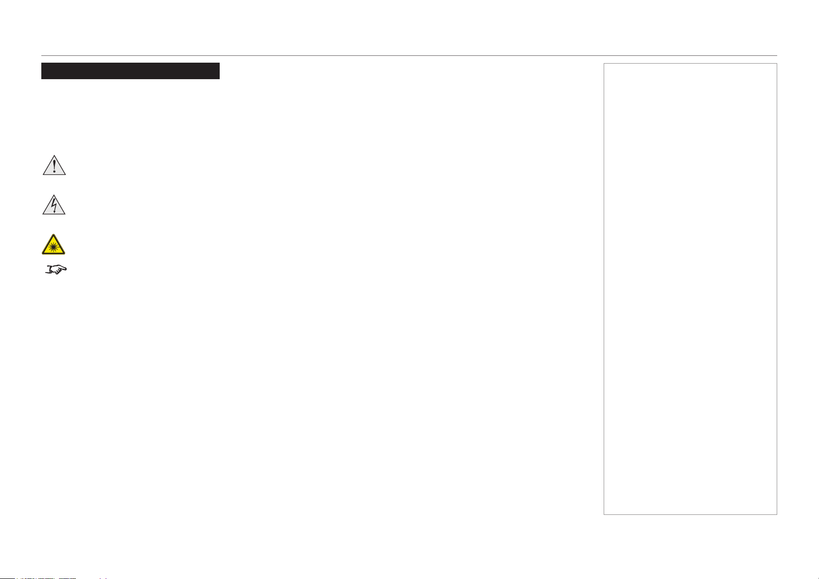
Symbols used in this manual
Many pages in this document have a dedicated area for notes. The information in that area is accompanied by the following symbols:
WARNING: this symbol indicates that there is a danger of physical injury to yourself and/or damage to the equipment unless
the instructions are closely followed.
ELECTRICAL WARNING: this symbol indicates that there is a danger of electrical shock unless the instructions are closely
followed.
LASER WARNING: this symbol indicates that there is a potential hazard of eye exposure to laser radiation unless the
instructions are closely followed.
NOTE: this symbol indicates that there is some important information that you should read.
Product revision
Because we at NEC continually strive to improve our products, we may change specications and designs, and add new features without
prior notice.
Legal notice
Trademarks and trade names mentioned in this document remain the property of their respective owners.
NEC disclaims any proprietary interest in trademarks and trade names other than its own.
Notes
page ii
Model No. NP-PH1201QL
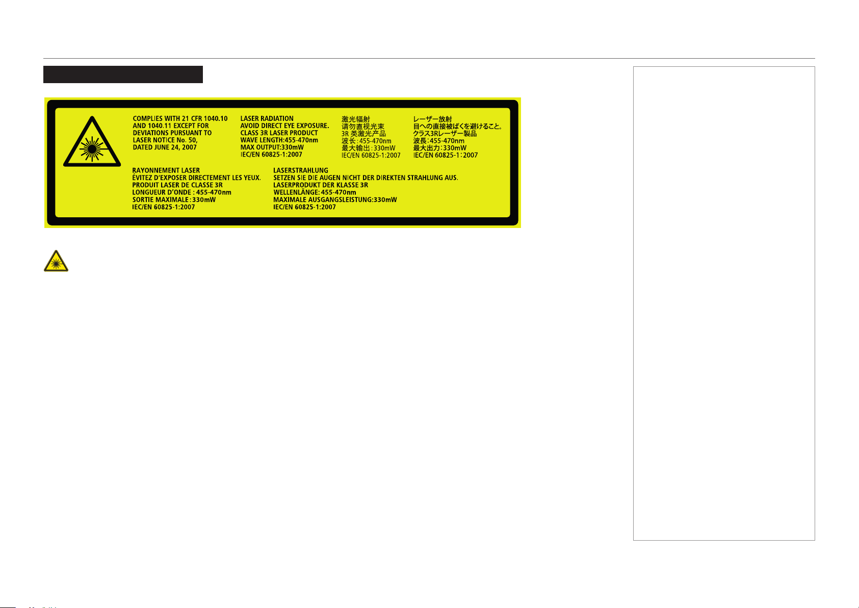
Laser Information
Caution-useofcontrolsoradjustmentsorperformanceofproceduresotherthanthosespeciedhereinmayresultin
hazardous radiation exposure.
NEC Display Solutions, Ltd.
4-28, Mita 1-chome, Minato-ku, Tokyo, Japan
Contact address for EMEA
NEC Display Solutions Europe GmbH
Landshuter Allee 12-14 80637 Munich, Germany
This device complies with part 15 of the FCC Rules.
Operation is subject to the following two conditions:
(1) This device may not cause harmful interference, and
(2) This device must accept any interference received,
including interference that may cause undesired operation.
Complies with FDA performance standards for laser products
except for deviations pursuant to Laser Notice No. 50,
dated June 24, 2007
CAN ICES-3 (A)/NMB-3(A)
Tegangan dan Frekuensi : 200-240V ~ 50/60Hz
Produksi UK
Made in UK
This cabinet is constructed of Metal(AL) and Plastic(PC/ABS)
E176726
NWGQ
115-364C
Notes

page iii
Model No. NP-PH1201QL
Introduction
Your projector has the following key features:
• 4K resolution up to 60 fps.
• Full 4K 3D display capability.
• Scaling 2K resolution to 4K resolution.
• Quad 3G-SDI interface for 4K 60fps.
• Control via LAN and RS232.
• Motorised lens mount.
A serial number is located on the product label. Record it here:
Notes

page iv
Model No. NP-PH1201QL
CONTENTS
INSTALLATION AND QUICK-START GUIDE ..............................1
WHAT’S IN THE BOX? ................................................................... 3
POWER SUPPLY ............................................................................ 4
AC power work specications ............................................................... 4
AC power supply equipment ..................................................................... 4
AC power supply cable for the projector ....................................................... 5
Connector ............................................................................................ 6
Connecting the power supply ................................................................ 7
PROJECTOR OVERVIEW ............................................................... 8
Front and rear views ............................................................................. 8
Control panel ......................................................................................... 9
Control panel button indicators ........................................................... 10
Status indicators.................................................................................. 11
POSITIONING THE SCREEN AND PROJECTOR ........................... 12
Tilting restrictions ................................................................................ 13
Pitch ................................................................................................. 13
Roll .................................................................................................. 13
LENS ASSEMBLY AND FITTING ................................................... 14
Assembling the lens ............................................................................ 14
Inserting a new lens ............................................................................ 16
Removing the lens .............................................................................. 19
CLEANING AND REPLACING THE FILTERS ................................ 21
General notes...................................................................................... 21
Cleaning the air lters ........................................................................... 21
Replacing the air lters .......................................................................... 21
Rear lters ........................................................................................... 22
Front lter ............................................................................................ 24
Reset the air lter usage time ............................................................. 26
OPERATING THE PROJECTOR .................................................... 27
Switching the projector on ................................................................... 27
Switching the projector off ................................................................... 28
Selecting a title or test pattern............................................................. 29
Selecting a title.................................................................................... 29
Selecting a test pattern .......................................................................... 30
Adjusting the lens ................................................................................ 31
Adjusting the brightness ...................................................................... 32
CONNECTION GUIDE ............................................................................33
SIGNAL INPUTS .......................................................................... 35
SDI and DVI inputs.............................................................................. 35
3D Sync ............................................................................................ 36
Indicators on the terminal panel ............................................................... 37
EDID on the DVI inputs ....................................................................... 38
Using HDMI/DVI/DisplayPort switchers with the projector ............................... 38
CONTROL CONNECTIONS ........................................................... 39

page v
Model No. NP-PH1201QL
OPERATING GUIDE ................................................................................41
USING THE CONTROL PANEL ..................................................... 43
LCD display overview.......................................................................... 43
In STANDBY mode .............................................................................. 43
In operation ........................................................................................ 43
When showing menus ........................................................................... 44
Locking and unlocking the control panel ............................................. 45
Working with menus ........................................................................... 46
Entering alphanumeric values ................................................................. 46
USING THE PROJECTOR ............................................................. 47
Title Select menu ................................................................................ 47
Selecting a test pattern .......................................................................... 47
Conguration menu ............................................................................. 48
Light Setup ........................................................................................ 48
Lens Control ....................................................................................... 48
Reset................................................................................................ 48
Information menu ................................................................................ 49
Light Output ....................................................................................... 49
Preset Button ...................................................................................... 49
Usage ............................................................................................... 49
Error Code ......................................................................................... 49
Version ............................................................................................. 50
IP Address ......................................................................................... 51
Setup Date ......................................................................................... 51
Option Status ...................................................................................... 51
REFERENCE GUIDE ................................................................................53
THE DMD™ .................................................................................. 55
CHOOSING A LENS ..................................................................... 57
SCREEN REQUIREMENTS ........................................................... 58
Fitting the image to the DMD™ ........................................................... 58
Diagonal screen sizes ......................................................................... 59
Fitting the image to the screen ............................................................ 60
Positioning the screen and projector ................................................... 61
POSITIONING THE IMAGE ........................................................... 62
ASPECT RATIOS EXPLAINED ...................................................... 64
APPENDIX A: LENS PART NUMBERS .......................................... 65
APPENDIX B: SUPPORTED SIGNAL INPUT MODES .................... 66
Supported 4K signals - Option board .................................................. 66
Screen allocation of Option board input signals ........................................... 67
APPENDIX C: MENU MAP ............................................................ 68
APPENDIX D: WIRING DETAILS .................................................. 70
Signal inputs - option board ................................................................ 70
DVI .................................................................................................. 70
3G-SDI In .......................................................................................... 71
Control connections ............................................................................ 72
LAN ................................................................................................. 72
RS232 .............................................................................................. 72
3D Sync IN and 3D Sync OUT ................................................................ 72
CONTENTS (continued)

page vi
Model No. NP-PH1201QL
TECHNICAL SPECIFICATIONS .................................................... 73
Models................................................................................................. 73
Inputs and outputs............................................................................... 74
Bandwidth ........................................................................................... 74
Remote control and keypad ................................................................ 74
Automation control .............................................................................. 74
Color temperature ............................................................................... 74
Lenses................................................................................................. 75
Lens mount ......................................................................................... 75
Mechanical mounting .......................................................................... 75
Orientation........................................................................................... 75
Electrical and physical specications .................................................. 76
Safety & EMC regulations ................................................................... 76
CAD drawings ..................................................................................... 77
NEC CONTACTS .......................................................................... 78
CONTENTS (continued)

Model No. NP-PH1201QL
This page is intentionally left blank.

Model No. NP-PH1201QL
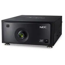
Projector
PH1201QL
Installation and Quick-Start Guide

Model No. NP-PH1201QL
Installation and Quick-Start Guide
IN THIS GUIDE
IN THIS GUIDE
What’s In The Box? ............................................................................................. 3
Power Supply ........................................................................................................ 4
ACpowerworkspecications ...................................................................................4
AC power supply equipment ............................................................................................. 4
AC power supply cable for the projector ........................................................................... 5
Connector ......................................................................................................................... 6
Connecting the power supply .................................................................................... 7
Projector Overview ............................................................................................. 8
Front and rear views ...................................................................................................8
Control panel ...............................................................................................................9
Control panel button indicators ...............................................................................10
Status indicators .......................................................................................................11
Positioning The Screen And Projector ....................................................... 12
Tilting restrictions .....................................................................................................13
Pitch ................................................................................................................................13
Roll ..................................................................................................................................13
Lens Assembly And Fitting ............................................................................ 14
Assembling the lens .................................................................................................14
Inserting a new lens ..................................................................................................16
Removing the lens ....................................................................................................19
Cleaning And Replacing The Filters ........................................................... 21
General notes ............................................................................................................21
Cleaning the air lters .....................................................................................................21
Replacing the air lters ...................................................................................................21
Rearlters .................................................................................................................22
Frontlter ..................................................................................................................24
Resettheairlterusagetime ..................................................................................26
Operating The Projector ................................................................................. 27
Switching the projector on .......................................................................................27
Switching the projector off .......................................................................................28
Selecting a title or test pattern .................................................................................29
Selecting a title ................................................................................................................29
Selecting a test pattern ...................................................................................................30
Adjusting the lens .....................................................................................................31
Adjusting the brightness ..........................................................................................32
page 3
Model No. NP-PH1201QL
Installation and Quick-Start Guide
WHAT’S IN THE BOX?
What’s In The Box?
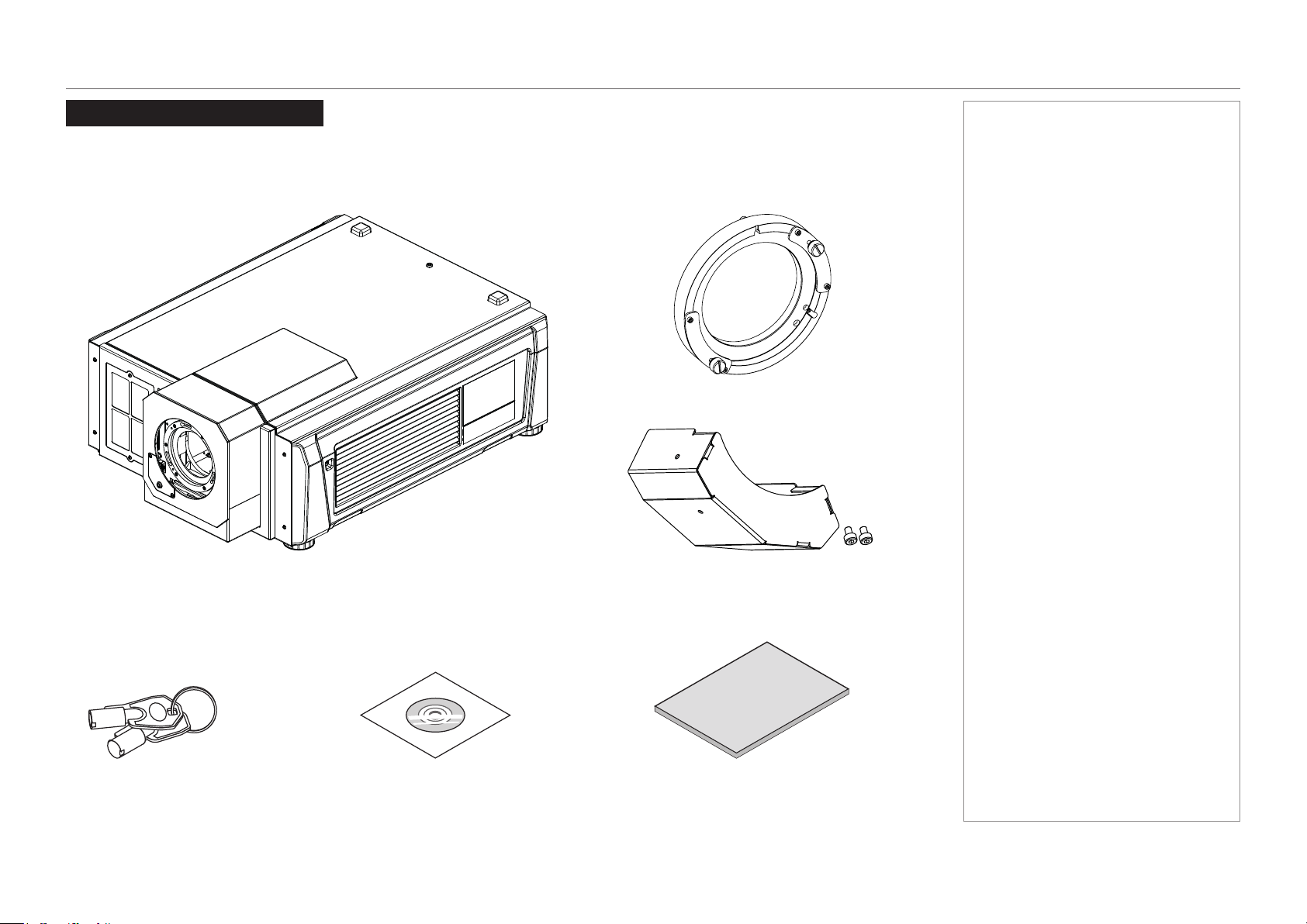
Make sure your box contains everything listed. If any pieces are missing, contact your dealer.
Please save the original box and packing materials if you ever need to ship your projector.
Notes
NP-PH1201QL projector (without lens) x 1
lens holder x 1
service keys x 2 User Manual CD x 1 Important Information x 1
lens gearbox cover x 1
(incl. M2 socket head screws x 2)

page 4
Model No. NP-PH1201QL
Installation and Quick-Start Guide
POWER SUPPLY
Power Supply
The power cable is not included with the projector. Refer to the AC power work specications section below and provide the necessary
power cable.
AC power work specications
AC power supply equipment
Do not use any voltage other than those shown below for the AC power supply connected to the projector:
• 200–240V AC, single phase, power, 50/60Hz
Notes
Carefully read the contents
described in this section before
connection and connect the
cables according to the proper
procedure. Inappropriate handling
may cause fatal, serious or other
bodilyinjuriesduetoreor
electric shock.
Before connecting the power
cables, check that the main power
switch of the projector is turned
off. Implement the connection
with AC power shut off.
Be sure to ground the equipment
to ensure safety. Use a power
cable that meets the standards
and power supply voltage of the
country where you are using the
projector and always connect the
equipment to the ground. If the
ground is not connected, it may
cause electrical shocks.
When connecting the power
cable plugs to the AC IN and the
electrical outlet, securely insert
the plugs all the way in. If the
connection between the power
cable plug and the electrical
outlet is loose, the plug area may
generate heat, causing burns and
accidents.
Users in North America:
Use a power cable no longer
than 4.5 m / 14.76 ft according to
National Electrical Code.
page 5
Model No. NP-PH1201QL
Installation and Quick-Start Guide
POWER SUPPLY
AC power supply cable for the projector
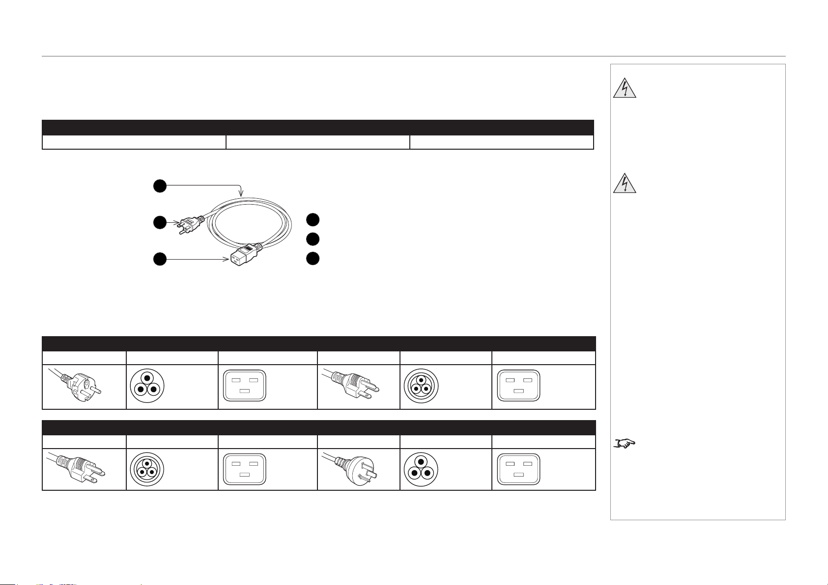
The projector is equipped with an IEC60320 C20 inlet to connect an AC power supply cable. Use an IEC60320 C19 compliant AC power cable
connector and ensure that the connector meets the following current capacity specications.
Power supply voltage Projector input current Power cable current capacity
AC 200-240 V 8.2 A 250 V 15 A or higher
Furthermore, use cables, plugs and connectors that are suitable for the regulations of the country of installation, as shown in the following table.
Germany Japan
Plug: CEE7 Cable: H05VV-F 3G1.5 Connector: IEC 320 C19 Plug: JIS C 8303 Cable: VCTF 3 x 2.0mm Connector: IEC 320 C19
USA China
Plug: NEMA 6-15P Cable: SJT 3 x AWG 14 Connector: IEC 320 C19 Plug: GB2099 Cable: RVV 300/500 Connector: GB17465.1
Notes
Carefully read the contents
described in this section before
connection and connect the
cables according to the proper
procedure. Inappropriate handling
may cause fatal, serious or other
bodilyinjuriesduetoreor
electric shock.
Before connecting the power
cables, check that the main power
switch of the projector is turned
off. Implement the connection
with AC power shut off.
Be sure to ground the equipment
to ensure safety. Use a power
cable that meets the standards
and power supply voltage of the
country where you are using the
projector and always connect the
equipment to the ground. If the
ground is not connected, it may
cause electrical shocks.
When connecting the power
cable plugs to the AC IN and the
electrical outlet, securely insert
the plugs all the way in. If the
connection between the power
cable plug and the electrical
outlet is loose, the plug area may
generate heat, causing burns and
accidents.
Users in North America:
Use a power cable no longer
than 4.5 m / 14.76 ft according to
National Electrical Code.
1
Cable
2
Plug
3
Connector
2
3
1
page 6
Model No. NP-PH1201QL
Installation and Quick-Start Guide
POWER SUPPLY
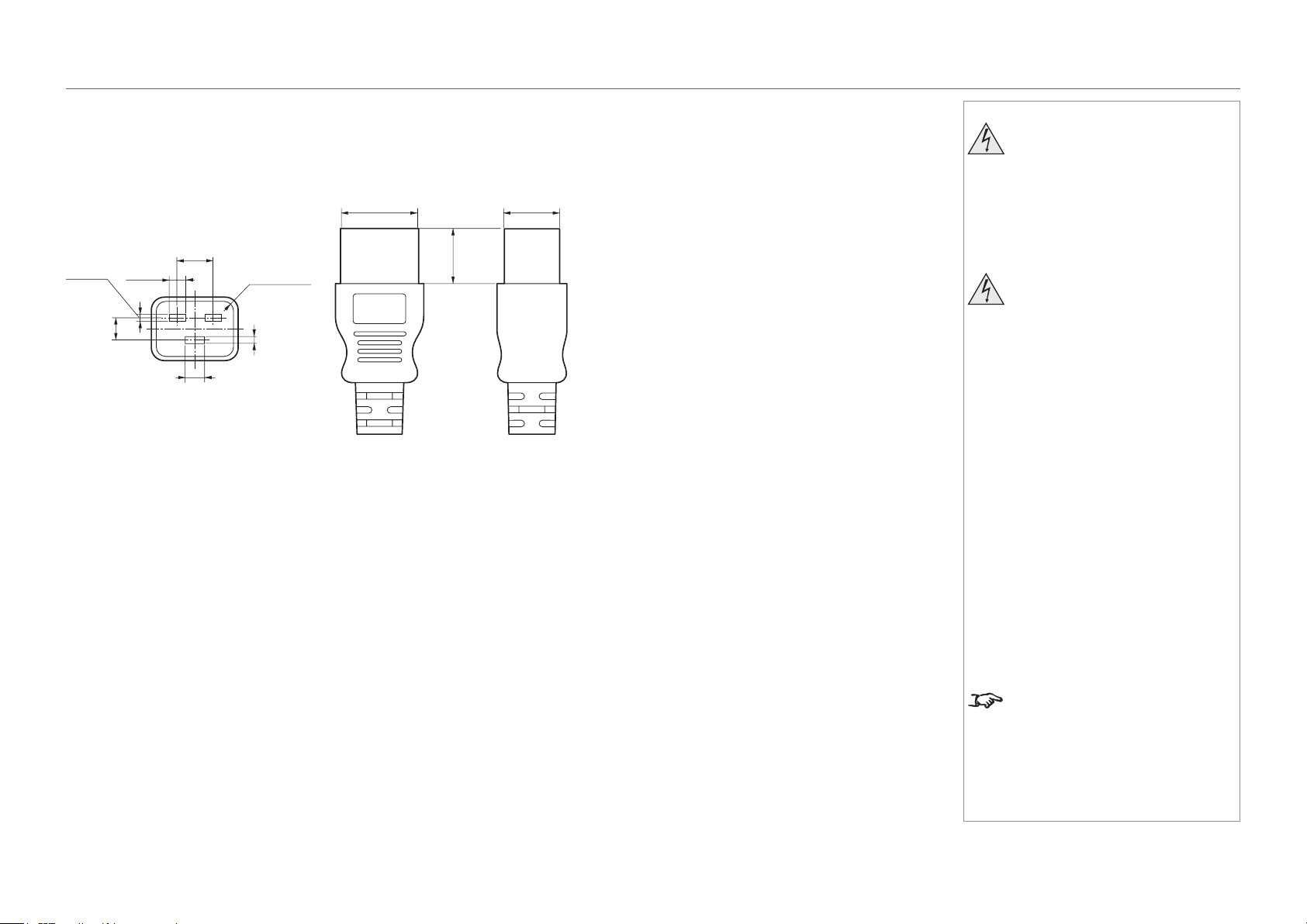
Connector
Dimensions of the connector of the power cable are shown below.
Notes
Carefully read the contents
described in this section before
connection and connect the
cables according to the proper
procedure. Inappropriate handling
may cause fatal, serious or other
bodilyinjuriesduetoreor
electric shock.
Before connecting the power
cables, check that the main power
switch of the projector is turned
off. Implement the connection
with AC power shut off.
Be sure to ground the equipment
to ensure safety. Use a power
cable that meets the standards
and power supply voltage of the
country where you are using the
projector and always connect the
equipment to the ground. If the
ground is not connected, it may
cause electrical shocks.
When connecting the power
cable plugs to the AC IN and the
electrical outlet, securely insert
the plugs all the way in. If the
connection between the power
cable plug and the electrical
outlet is loose, the plug area may
generate heat, causing burns and
accidents.
Users in North America:
Use a power cable no longer
than 4.5 m / 14.76 ft according to
National Electrical Code.
7
+0,5
-
0
28
+0
-
0,9
20
+0
-
0,7
6,0
+0,5
-
0
2,5
+0,5
-
0
2,5
+0,5
-
0
8
±
0,2
13 ±0,2
Unit: mm
R3.5 min
20 min
page 7
Model No. NP-PH1201QL
Installation and Quick-Start Guide
POWER SUPPLY
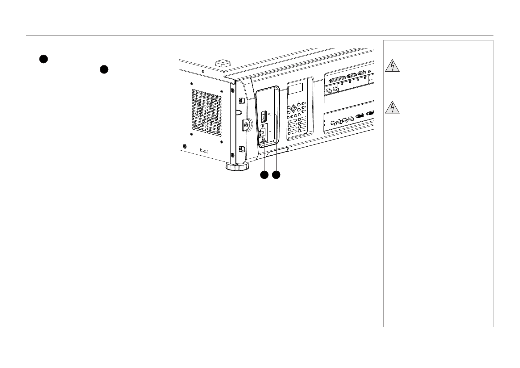
Connecting the power supply
When the projector is viewed from the back, the AC mains
inlet
1
is located on the right hand side, toward the rear.
Make sure the power switch
2
above the inlet is in the
OFF position, then push the mains connector in rmly.
1
2
Notes
Ensure that the power outlet
includes a ground connection as
this equipment MUST be earthed.
Handle the power cable carefully
and avoid sharp bends. Do not
use a damaged power cable.
page 8
Model No. NP-PH1201QL
Installation and Quick-Start Guide
PROJECTOR OVERVIEW
Projector Overview
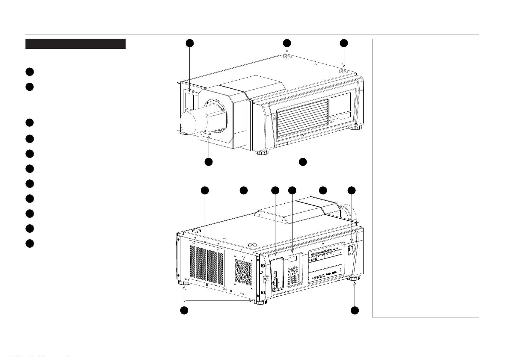
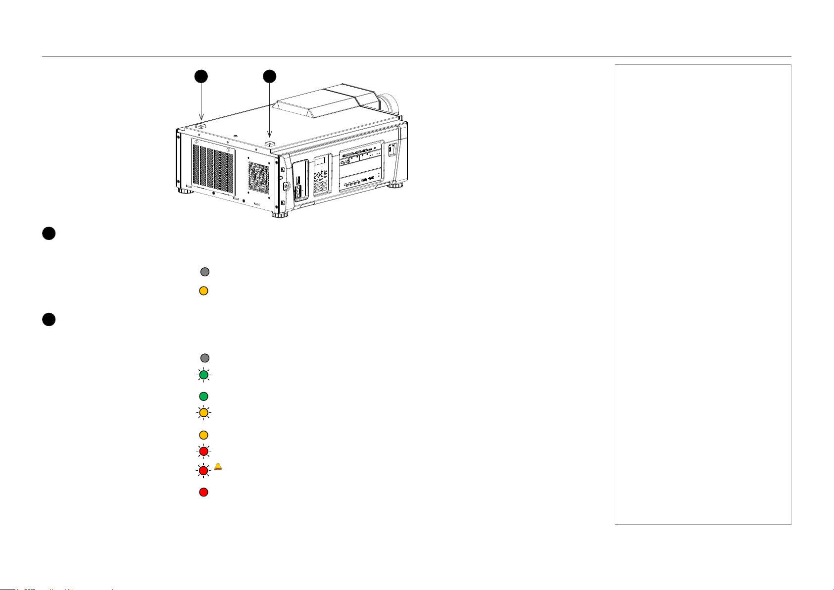
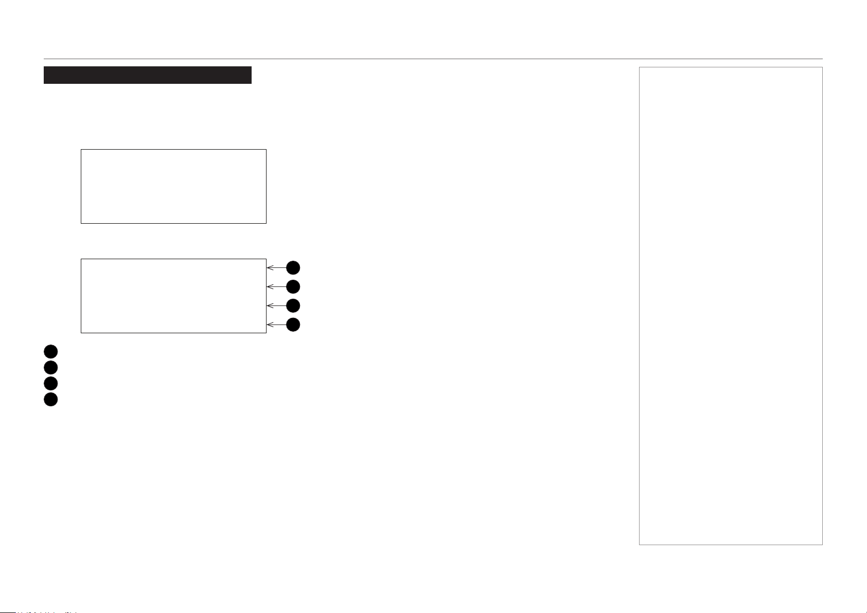
Front and rear views
1
Airinletandlter
2
SYSTEM status indicator
When the projector is operating normally, this
indicator lights green or orange. If an error
occurs, the light becomes red. Depending on the
scenario, the light can be steady or ashing.
3
LIGHT status indicator
Turns on when the light source is switched on.
4
Lens
5
Air outlet
6
Airinletandlter
7
Air outlet
8
Power switch and power connection
9
Control panel with LED screen
10
Connections
11
Adjustable feet
Notes
Front view
4
32
5
1
Rear view
11
7 86
11
9 10 10
page 9
Model No. NP-PH1201QL
Installation and Quick-Start Guide
PROJECTOR OVERVIEW
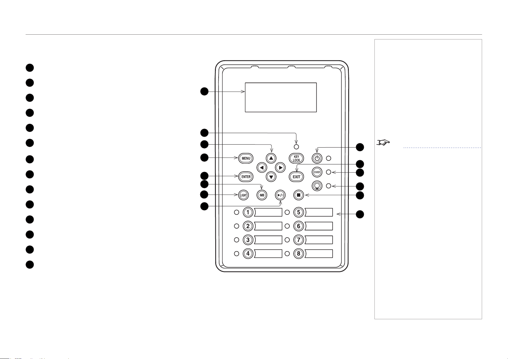
Control panel
1
LCD display
2
KEY LOCK button (with indicator)
3
Arrow buttons
4
MENU button
5
ENTER button
6
not used in this conguration
(except for entering alphanumeric values)
7
LIGHT button
8
not used in this conguration
9
POWER button (with indicator)
10
EXIT button
11
DOUSER button (with indicator)
12
LIGHT ON / OFF button (with indicator)
13
not used in this conguration
14
Preset buttons 1 to 8 (with indicators)
Notes
See Entering alphanumeric values
in the Operating Guide.
1
10
4
7
14
3
6
2
9
12
13
8
11
5
page 10
Model No. NP-PH1201QL
Installation and Quick-Start Guide
PROJECTOR OVERVIEW
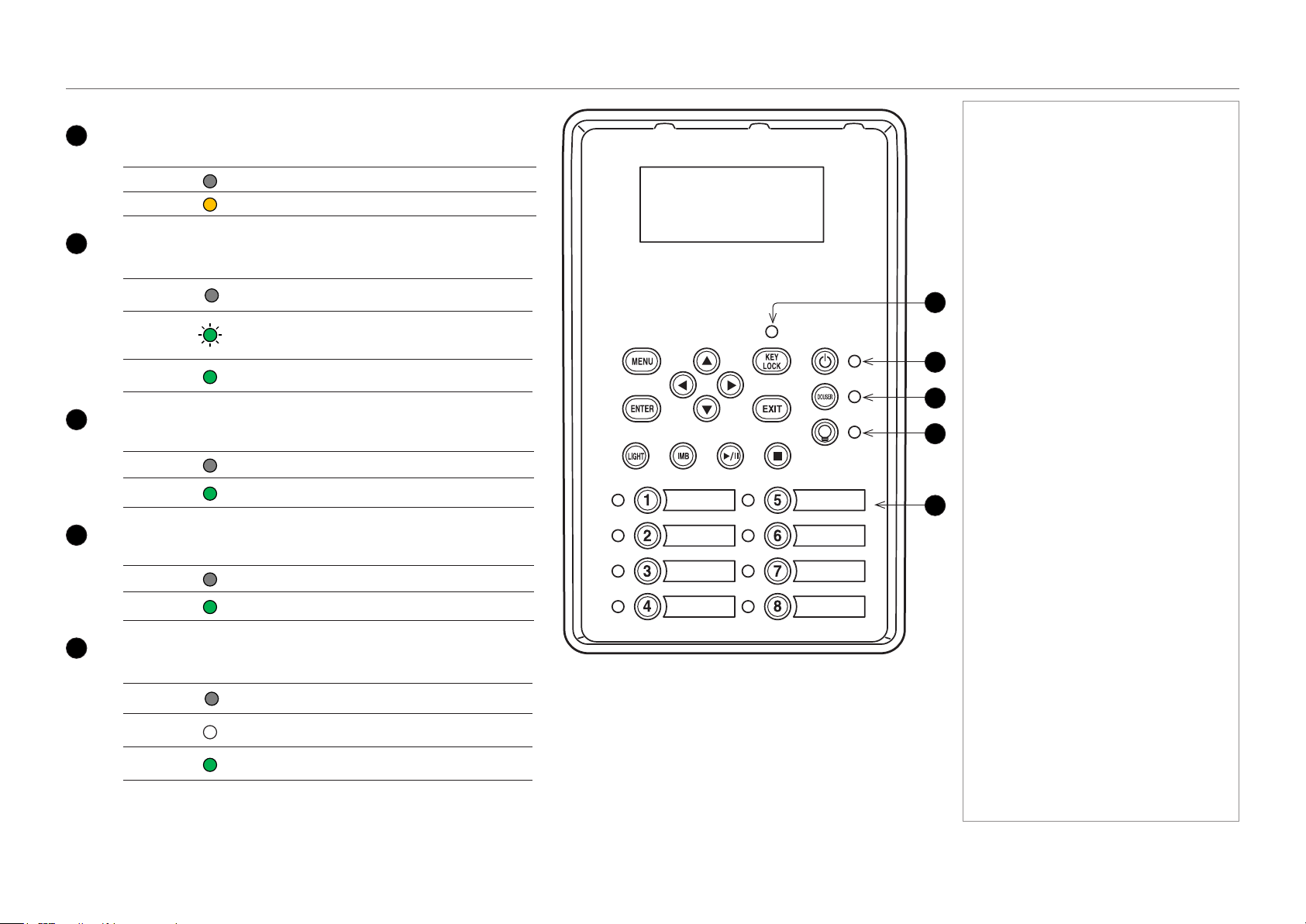
Control panel button indicators
1
KEY LOCK
Behavior Meaning
Off Key lock is inactive.
On Key lock is activated.
2
POWER ON / OFF
Behavior Meaning
Off
The projector is switched off from the power supply
or in STANDBY mode.
Flashing
green
The projector is warming up (preparing to switch ON)
or cooling down (preparing to switch OFF).
Steady
green
The projector is switched on.
3
DOUSER ON / OFF
Behavior Meaning
Off The douser is opened.
Steady
green
The douser is closed.
4
LIGHT ON / OFF
Behavior Meaning
Off The light source is switched off.
Steady
green
The light source is switched on.
5
Presets
Behavior Meaning
Off
The title is not assigned to the projector.
Steady
white
The title is assigned to the projector but is not
currently in use.
Steady
green
The title is assigned to the projector and is currently
in use.
Notes
1
5
4
2
3
page 11
Model No. NP-PH1201QL
Installation and Quick-Start Guide
PROJECTOR OVERVIEW
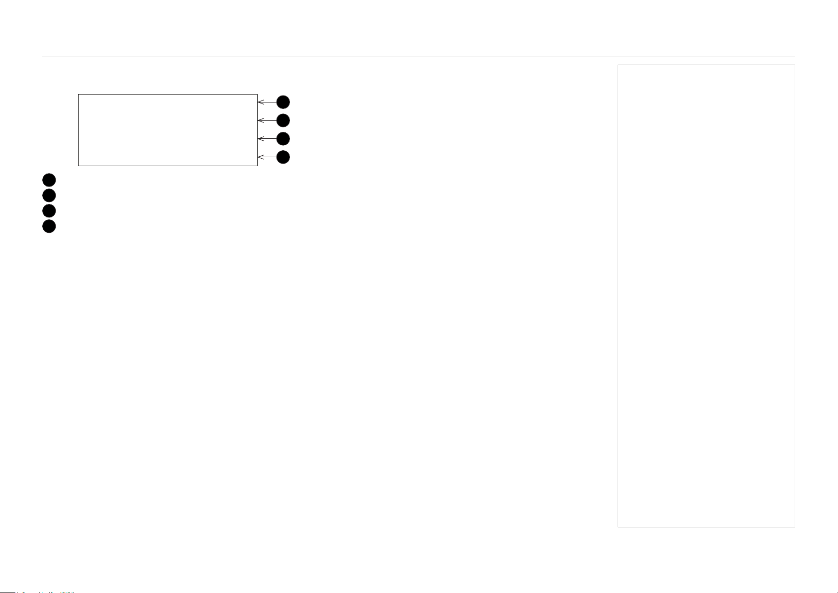
Status indicators
1
LIGHT status indicator
Behavior Meaning
Off The light source is switched off.
On The light source is switched on.
2
SYSTEM status indicator
Behavior Meaning
Off The projector is switched off.
Flashing green The projector is warming up. The douser is closed and the light source is off.
Steady green The projector is switched on.
Flashing amber The projector is cooling down.
Steady amber The projector is in standby.
Flashing red Error, projection cannot continue. Check LCD screen for error message.
Flashing red, with buzzer
Error with safety implications. Projection cannot continue. Check LCD screen for error message.
Steady red Non-fatal error, projection may continue. Check LCD screen for error message.
Notes
21
page 12
Model No. NP-PH1201QL
Installation and Quick-Start Guide
POSITIONING THE SCREEN AND PROJECTOR
Positioning The Screen And Projector
Installation should be carried out by authorised personnel only.
1. Install the screen, ensuring that it is in the best position for viewing by your audience.
2. Mount the projector, ensuring that it is at a suitable distance from the screen for the image to ll the screen. Set the adjustable feet so that
the projector is level, and perpendicular to the screen.
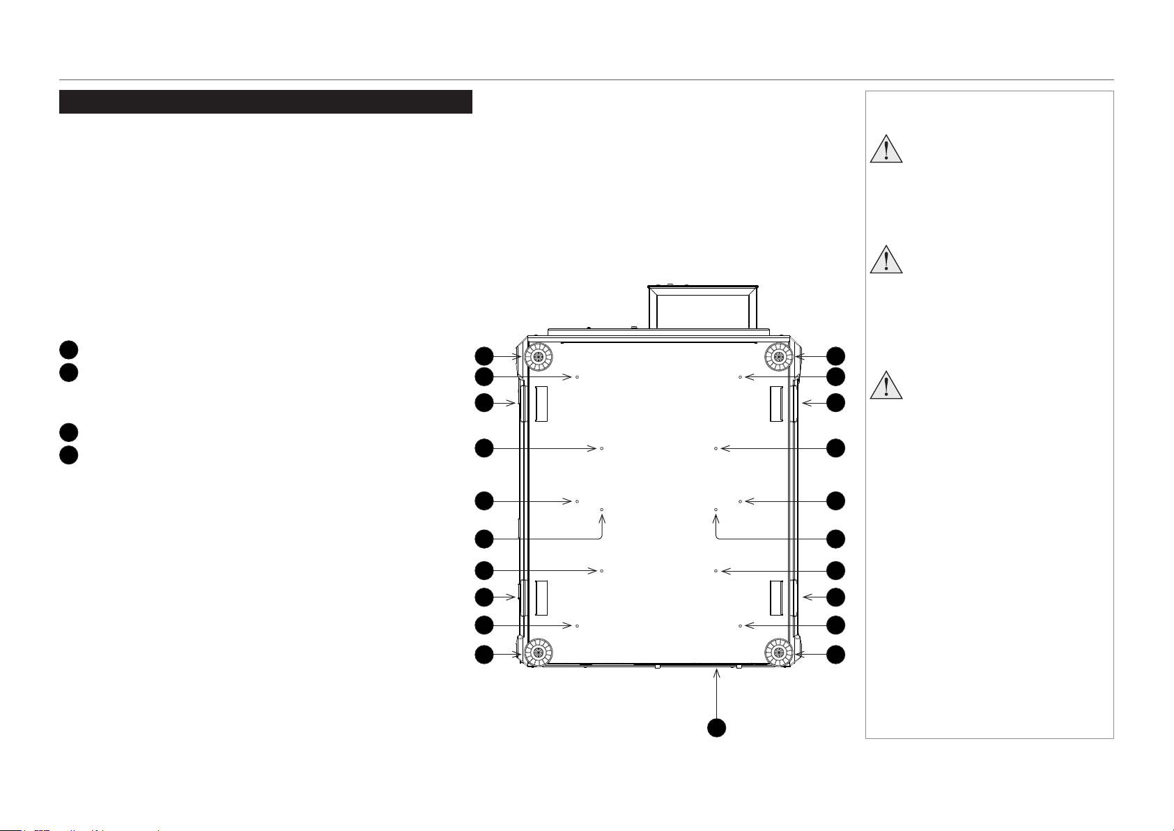
The drawing below shows the bottom of the projector. The positions of the feet for table mounting, and the xing holes for ceiling mounting
are clearly visible. The illustration also shows the positions of the four handles which facilitate safe carriage.
1
Four adjustable feet
2
Six M6 holes for ceiling mount (set A)
The screws should not penetrate more than 15 mm into the
body of the projector.
3
Handles for safe carriage
4
Six M6 holes for ceiling mount (set B)
The screws should not penetrate more than 15 mm into the
body of the projector.
1
2
1
1
1
2
2
2
2
2
3
3
3
3
4
4
4
4
44
Notes
Always allow the projector
to cool for 5 minutes before
disconnecting the power or
moving the projector.
Ensure that there is at least 30
cm (12 in) of space between the
ventilation outlets and any wall,
and 10 cm (4 in) on all other
sides.
Projectors are not designed to
be stacked on top of each other
unless a rigging frame is used.
3
page 13
Model No. NP-PH1201QL
Installation and Quick-Start Guide
POSITIONING THE SCREEN AND PROJECTOR
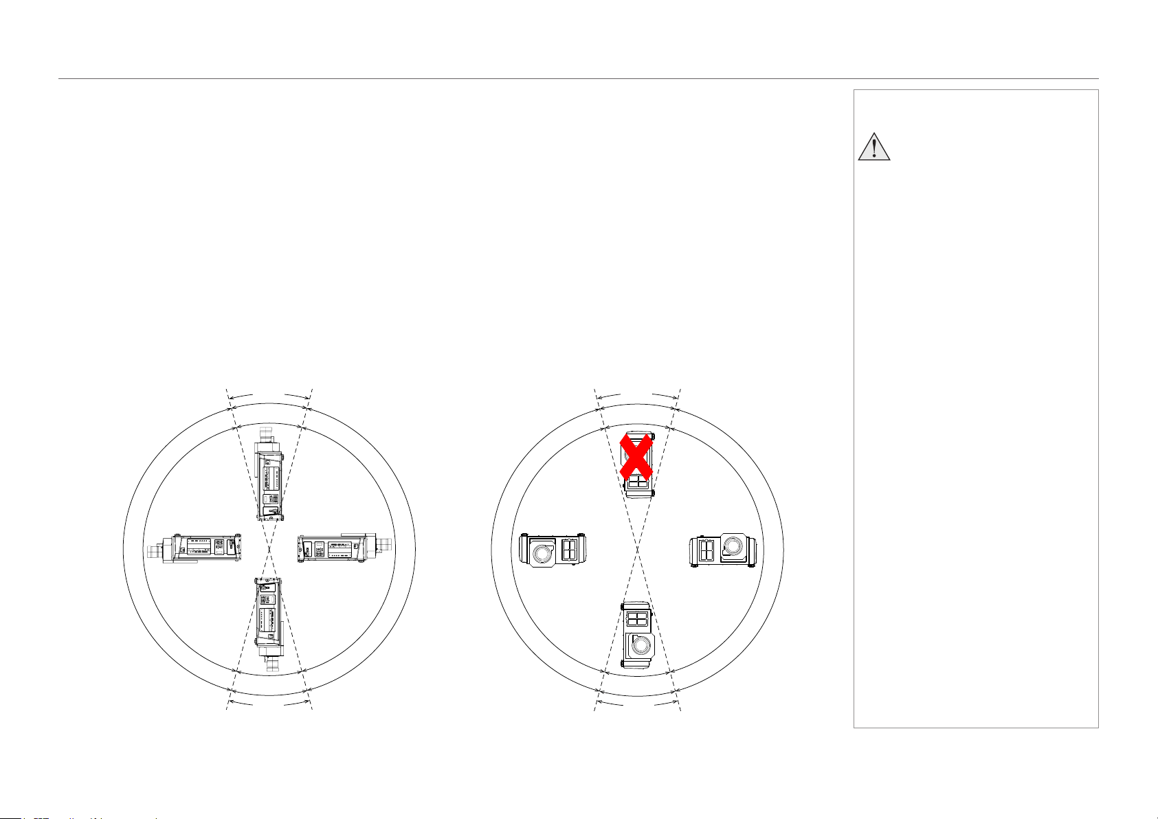
Tilting restrictions
The projector can be operated in numerous positions.
Pitch
The projector can be positioned at any angle around the pitch axis. Please consider the following:
• When the projector is within 15° to either side of the vertical plane, the temperature of the operating environment needs to be between 0
and 30°C.
• In every other position, the operating temperature is between 0 and 35°C.
Roll
The projector can be positioned in numerous positions around the roll axis. Please consider the following:
• The projector cannot be positioned within 15° to either side of the vertical plane (in portrait mode) with the inputs pointing downward.
• When the projector is within 15° to either side of the vertical plane (in portrait mode) with the inputs pointing upward, the temperature of
the operating environment needs to be between 0 and 30°C.
• In every other position, the operating temperature is between 0 and 35°C.
Notes
If you wish to use the projector
in portrait mode, please consult
your dealer in advance.
Do not attempt to install the
projector yourself.
Pitch
0-30°C
0-30°C
0
-
3
5
°
C
0
-
3
5
°
C
±15°
±15°
Roll
n
o
t
a
l
l
o
w
e
d
0-30°C
0
-
3
5
°
C
0
-
3
5
°
C
±15°
±15°
page 14
Model No. NP-PH1201QL
Installation and Quick-Start Guide
LENS ASSEMBLY AND FITTING
Lens Assembly And Fitting
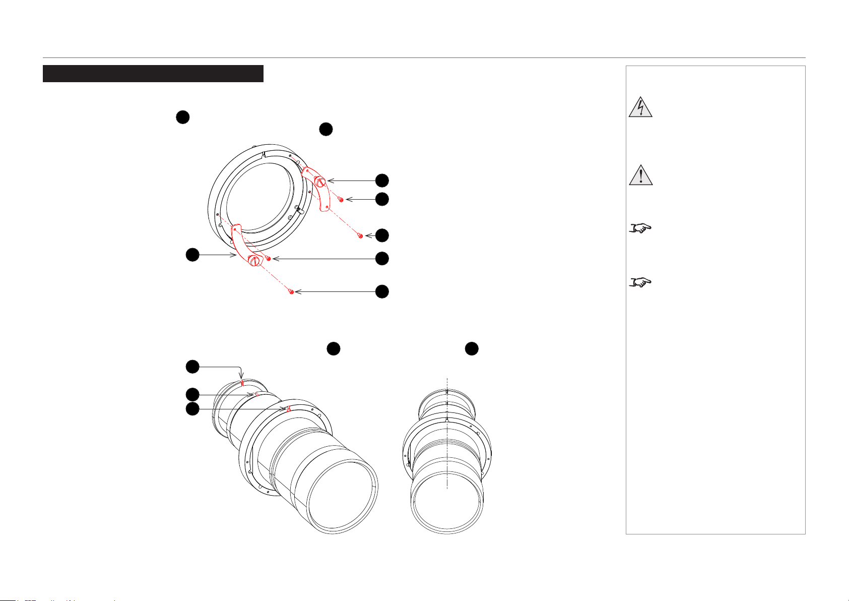
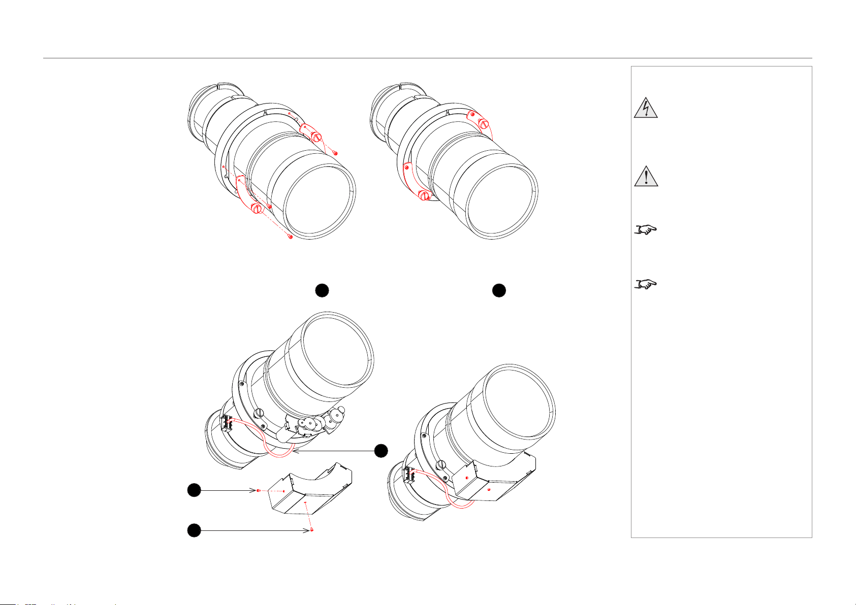
Assembling the lens
1. Detach the retaining plates
1
from the lens holder.
Use a 2.5 mm Allen key to remove the M3 socket head screws
2
.
2. Insert the lens into the lens holder. Align the notches on the lens
3
with the notch on the holder
4
.
Notes
Before changing the lens, always
make sure the projector is switched
off and fully disconnected from its
power supply.
When changing the lens, avoid using
excessive force as this may damage
the equipment.
Take care to preserve the original lens
packaging and protective caps for future
use.
The projector will not power on without
the lens tted.
1
2
2
1
2
2
3
3
4
page 15
Model No. NP-PH1201QL
Installation and Quick-Start Guide
LENS ASSEMBLY AND FITTING
3. Keeping the lens and holder aligned, secure the retaining plates removed earlier.
4. Attach the motor cover using the two M2 socket head screws
1
provided. Ensure the connector cable
2
is not trapped.
Notes
Before changing the lens, always
make sure the projector is switched
off and fully disconnected from its
power supply.
When changing the lens, avoid using
excessive force as this may damage
the equipment.
Take care to preserve the original lens
packaging and protective caps for future
use.
The projector will not power on without
the lens tted.
1
1
2
page 16
Model No. NP-PH1201QL
Installation and Quick-Start Guide
LENS ASSEMBLY AND FITTING
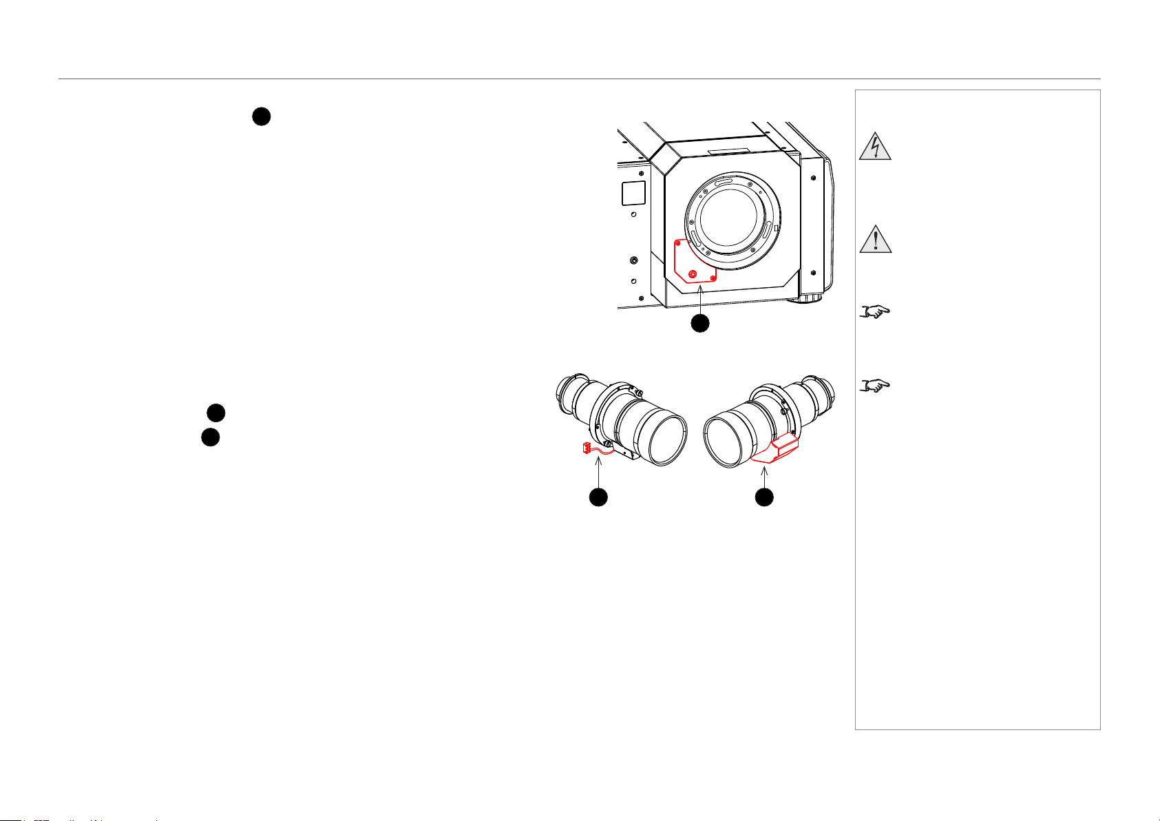
Inserting a new lens
1. Remove the connector cover
1
: it is held in position by two screws and a key.
2. Position the lens so that, if viewed from the front:
• the control cable
2
is on the left
• the motor cover
3
is on the right
Notes
Before changing the lens, always
make sure the projector is switched
off and fully disconnected from its
power supply.
When changing the lens, avoid using
excessive force as this may damage
the equipment.
Take care to preserve the original lens
packaging and protective caps for future
use.
The projector will not power on without
the lens tted.
2 3
1
page 17
Model No. NP-PH1201QL
Installation and Quick-Start Guide
LENS ASSEMBLY AND FITTING
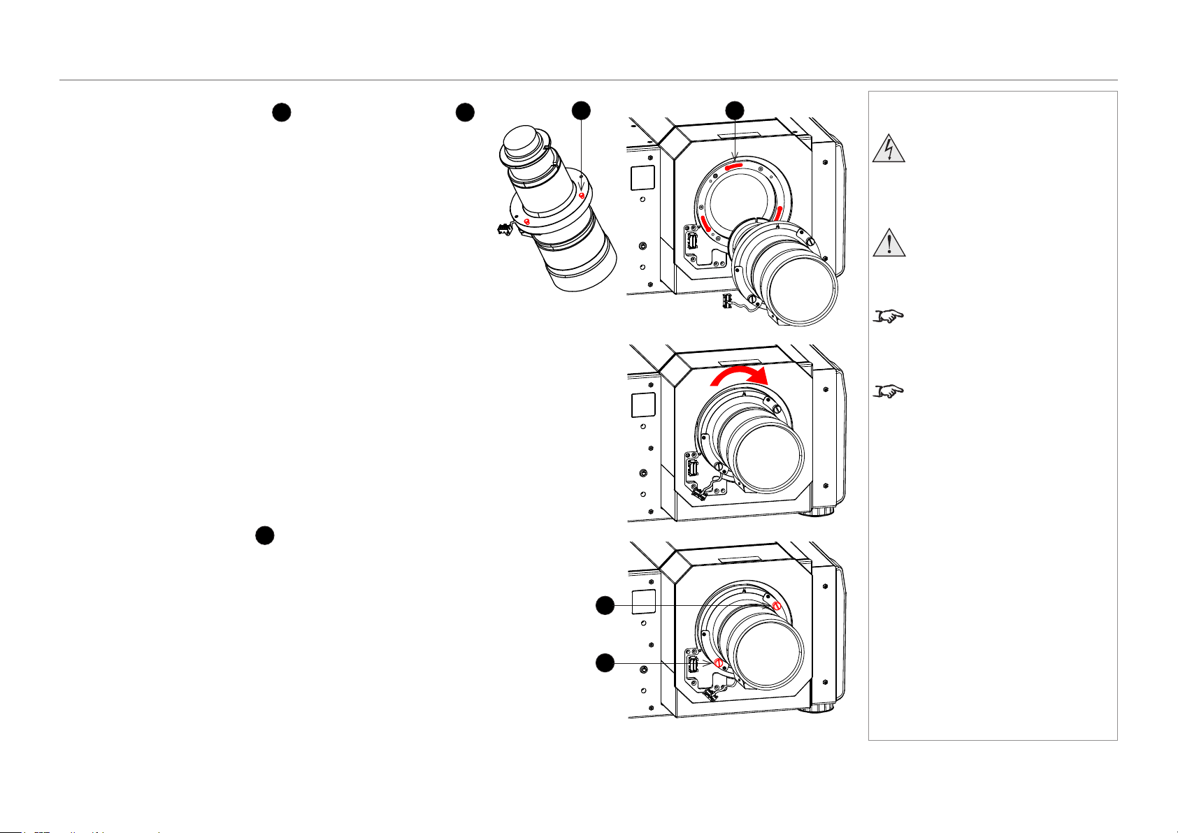
3. Insert the lens into the mount.
Engage the three locating studs
1
into the corresponding slots
2
on the mount.
4. Rotate the lens clockwise until the studs slide all the way into the
slots.
5. Tighten the two xing screws
3
on the lens holder.
Notes
Before changing the lens, always
make sure the projector is switched
off and fully disconnected from its
power supply.
When changing the lens, avoid using
excessive force as this may damage
the equipment.
Take care to preserve the original lens
packaging and protective caps for future
use.
The projector will not power on without
the lens tted.
1 2
3
3
page 18
Model No. NP-PH1201QL
Installation and Quick-Start Guide
LENS ASSEMBLY AND FITTING
6. Insert the control cable plug into the connector socket
1
.
Place the excess wire behind the front cover of the projector.
7. Replace the connector cover, making sure the cable is not trapped.
Notes
Before changing the lens, always
make sure the projector is switched
off and fully disconnected from its
power supply.
When changing the lens, avoid using
excessive force as this may damage
the equipment.
Take care to preserve the original lens
packaging and protective caps for future
use.
The projector will not power on without
the lens tted.
1
page 19
Model No. NP-PH1201QL
Installation and Quick-Start Guide
LENS ASSEMBLY AND FITTING
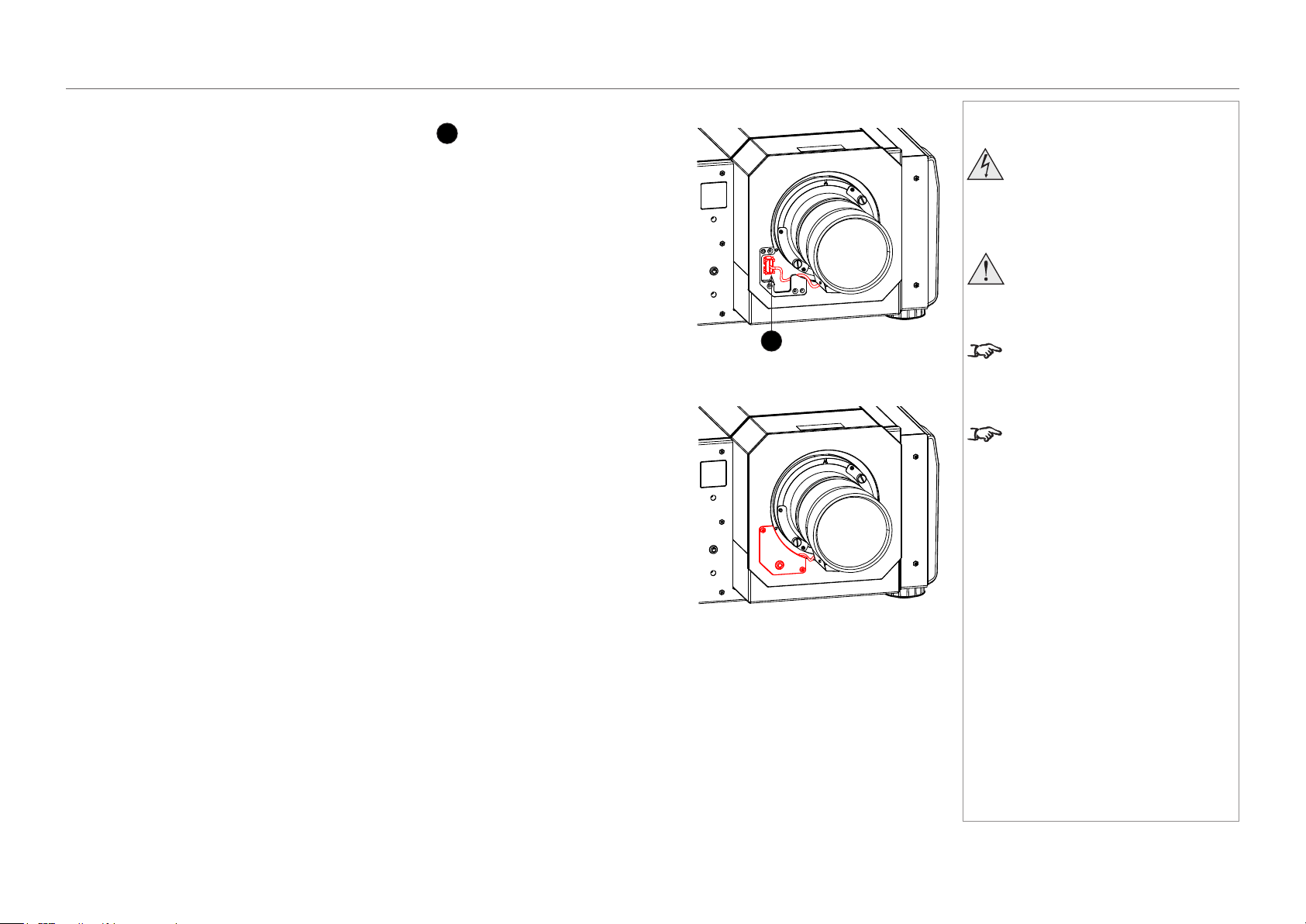
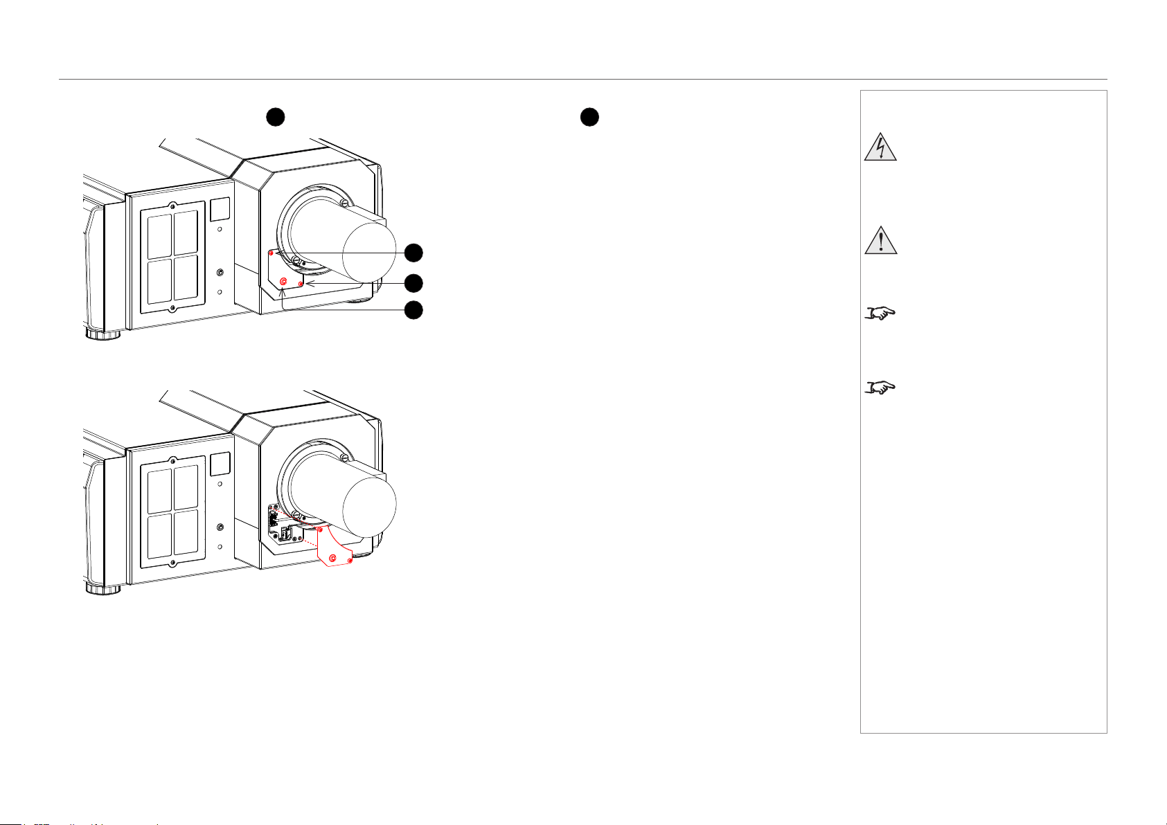
Removing the lens
1. Loosen the two captive screws
1
on the lens remote lock cover, then release the lock
2
using the provided key.
2. Remove the cover.
Notes
Before changing the lens, always
make sure the projector is switched
off and fully disconnected from its
power supply.
When changing the lens, avoid using
excessive force as this may damage
the equipment.
Take care to preserve the original lens
packaging and protective caps for future
use.
The projector will not power on without
the lens tted.
1
1
2
page 20
Model No. NP-PH1201QL
Installation and Quick-Start Guide
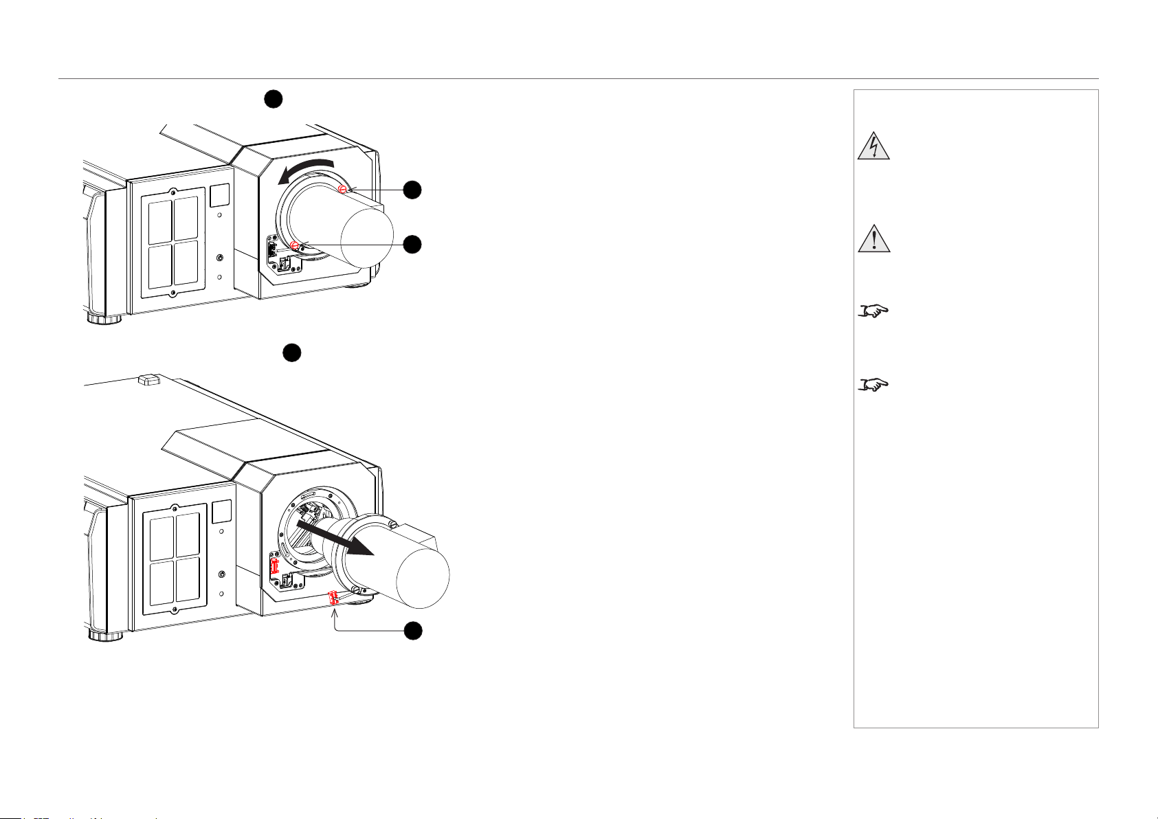
LENS ASSEMBLY AND FITTING
3. Loosen the two captive screws
3
on the lens and rotate the lens counterclockwise until it stops.
4. Unplug the remote lock connector
4
and pull the lens out of its socket.
Notes
Before changing the lens, always
make sure the projector is switched
off and fully disconnected from its
power supply.
When changing the lens, avoid using
excessive force as this may damage
the equipment.
Take care to preserve the original lens
packaging and protective caps for future
use.
The projector will not power on without
the lens tted.
3
3
4
page 21
Model No. NP-PH1201QL
Installation and Quick-Start Guide
CLEANING AND REPLACING THE FILTERS
Cleaning And Replacing The Filters
General notes
Air lters are attached over the air inlet of the projector to prevent dust. The air lters should be cleaned periodically in order to maintain
projector performance. The air lters should also be replaced with new lters after roughly 10,000 hours.
To view the usage time of the air lters, on the LCD display, go to Information > Usage.
When ordering replacement air lters, specify the part number (NP-11AF01).
When replacing air lters, replace the air lter in the front panel of the projector (1 piece) and the air lters in the rear panel (2 pieces) at the
same time. If you do not replace the air lters at the same time, the usage time cannot be calculated correctly.
Cleaning the air lters
Please remember to clean the air lters when the lter usage time reaches 2000 hours.
When the air lter usage time reaches 2000 hours, the message FilterCleaning Time is shown on the display.
Please be careful not to damage the air lters when cleaning them. If you nd any damage, such as a hole on the surface of the air lter,
replace it with new one.
After cleaning the air lters, on the LCD display, select Conguration > Reset > FilterCleaning. The lter cleaning message will be turned
off.
Replacing the air lters
Please remember to replace the air lters when the lter usage time reaches 10,000 hours.
When the air lter usage time reaches 10,000 hours, the message Filter Time Over appears on the display.
After replacing the air lters, on the LCD display, select Conguration > Reset > Filter Usage to reset the air lter usage time.
Notes
Beforechangingthelters,
always make sure the projector
is switched off and fully
disconnected from its power
supply.
Whenchangingthelters,avoid
using excessive force as this may
damage the equipment.
The air lters should be cleaned
every 2000 hours and replaced
after approximately 10,000 hours to
maintain projector performance.
It may be required to clean the
air lters more frequently than
stated above, depending on the
circumstances. In order to maintain
steady performance from the
projector, frequent cleaning is
strongly recommended.
It may also be required to replace
the air lters more frequently than
stated above, depending on the
circumstances.
page 22
Model No. NP-PH1201QL
Installation and Quick-Start Guide
CLEANING AND REPLACING THE FILTERS
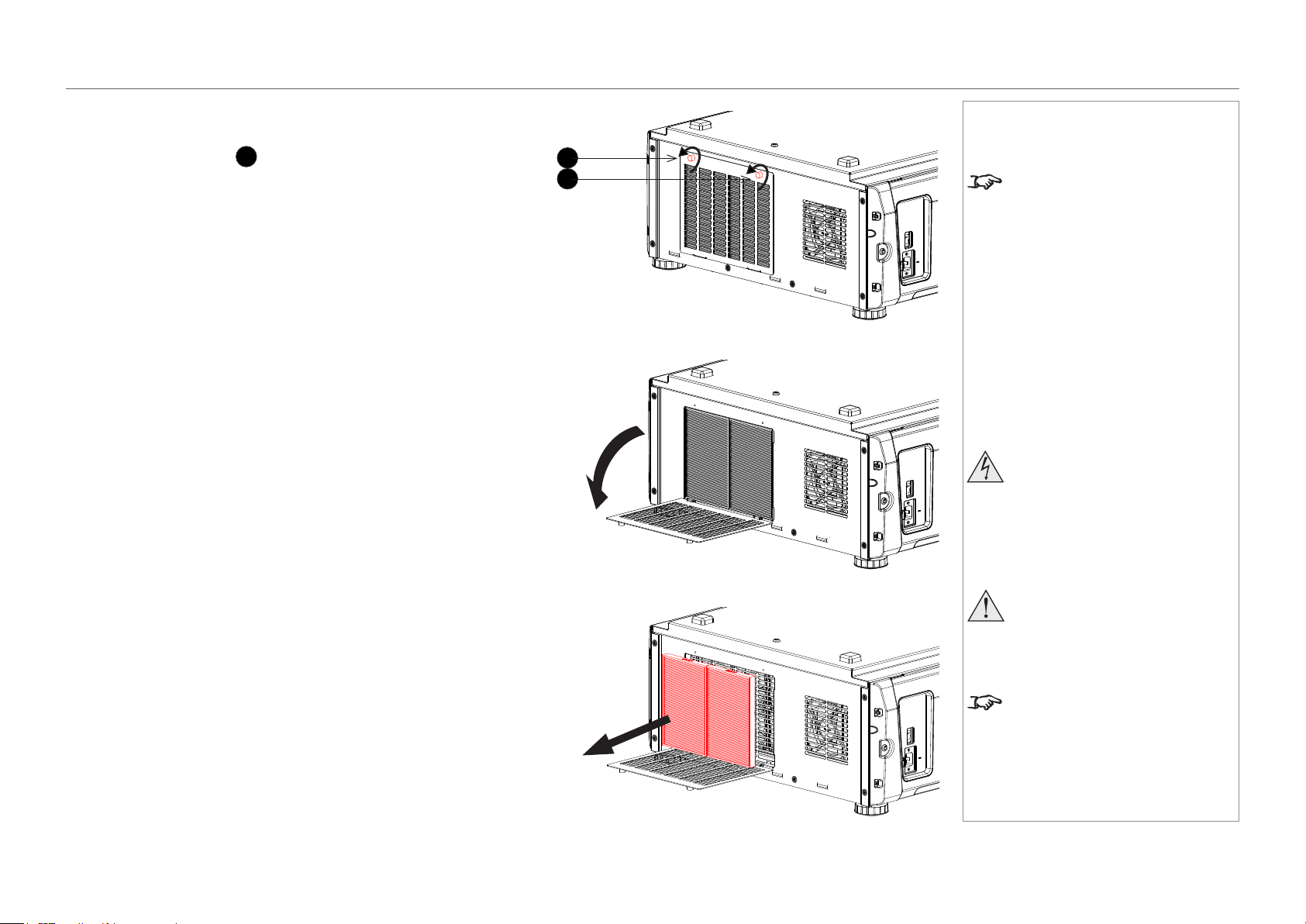
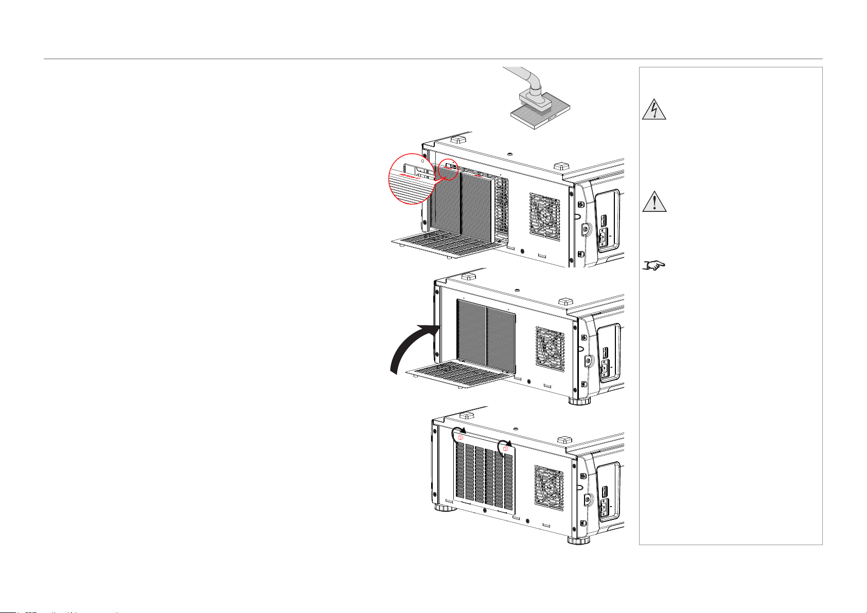
Rear lters
1. Loosen the two knobs
1
holding the lter cover by turning them
counterclockwise.
Use a Phillips screwdriver if necessary.
2. Tilt the lter cover to open it.
3. Remove the lters. Grasp the top and bottom or left and right ends of
each air lter and remove it by pulling toward you.
Notes
The knobs are captive on the
removable cover.
Beforechangingthelters,
always make sure the projector
is switched off and fully
disconnected from its power
supply.
Whenchangingthelters,avoid
using excessive force as this may
damage the equipment.
The air lters should be cleaned
every 2000 hours and replaced
after approximately 10,000 hours to
maintain projector performance.
1
1
page 23
Model No. NP-PH1201QL
Installation and Quick-Start Guide
CLEANING AND REPLACING THE FILTERS
4. If you are replacing the lters, skip this step.
To clean the lters, use a vacuum cleaner brush attachment to vacuum
away dust from the air lters. Avoid making direct contact without an
attachment or using a nozzle attachment.
5. Mount the air lters to the projector. Look for an arrow (AIR FLOW↑)
indicating the installation direction on the side of the air lter. Point the arrow
towards the projector.
6. Close the lter cover.
7. Tighten the knobs clockwise to secure the cover.
Notes
Beforechangingthelters,
always make sure the projector
is switched off and fully
disconnected from its power
supply.
Whenchangingthelters,avoid
using excessive force as this may
damage the equipment.
The air lters should be cleaned
every 2000 hours and replaced
after approximately 10,000 hours to
maintain projector performance.
page 24
Model No. NP-PH1201QL
Installation and Quick-Start Guide
CLEANING AND REPLACING THE FILTERS
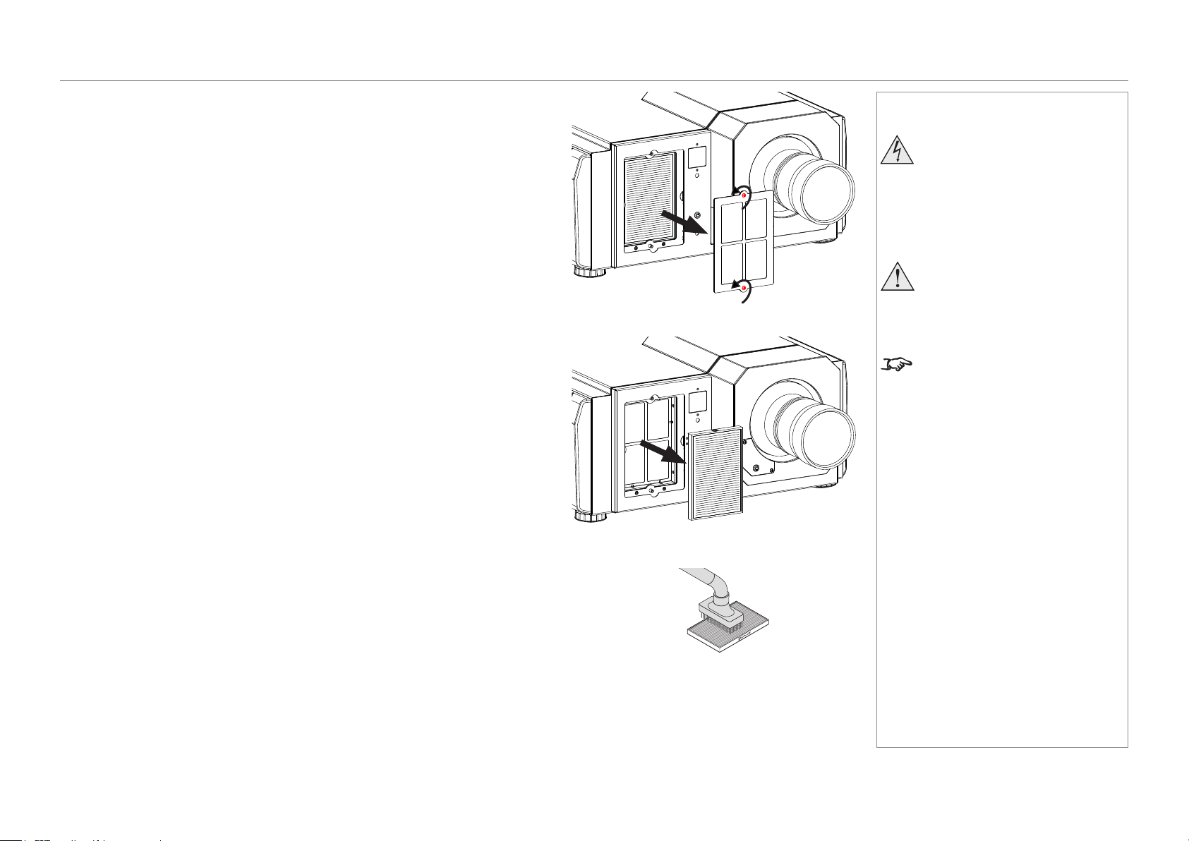
Front lter
1. Loosen the two captive screws on the lter cover and remove the cover.
2. Remove the air lter.
3. If you are replacing the lter, skip this step.
To clean the lter, use a vacuum cleaner brush attachment to vacuum away dust
from the air lter. Avoid making direct contact without an attachment or using a
nozzle attachment.
Notes
Beforechangingthelters,
always make sure the projector
is switched off and fully
disconnected from its power
supply.
Whenchangingthelters,avoid
using excessive force as this may
damage the equipment.
The air lters should be cleaned
every 2000 hours and replaced
after approximately 10,000 hours to
maintain projector performance.
page 25
Model No. NP-PH1201QL
Installation and Quick-Start Guide
CLEANING AND REPLACING THE FILTERS
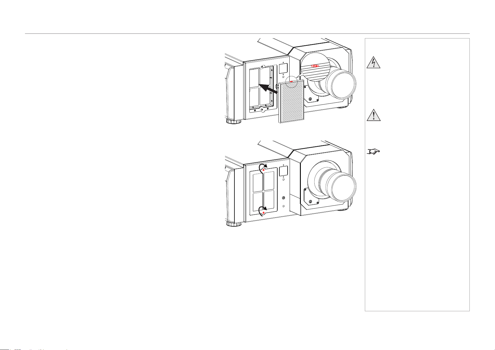
4. Mount the air lter to the projector.
Look for an arrow indicating the installation direction on the side of the air
lter. Point the arrow towards the projector.
5. Mount the lter cover to the projector. Tighten the two captive screws to
secure the cover.
Notes
Beforechangingthelters,
always make sure the projector
is switched off and fully
disconnected from its power
supply.
Whenchangingthelters,avoid
using excessive force as this may
damage the equipment.
The air lters should be cleaned
every 2000 hours and replaced
after approximately 10,000 hours to
maintain projector performance.

page 26
Model No. NP-PH1201QL
Installation and Quick-Start Guide
CLEANING AND REPLACING THE FILTERS
Reset the air lter usage time
1. Turn on the projector.
2. Open the menu and go to Conguration > Reset.
Filter Usage resets the lter usage time.
Notes
The air lters should be cleaned
every 2000 hours and replaced
after approximately 10,000 hours to
maintain projector performance.
Reset
Filter Usage
Reset
page 27
Model No. NP-PH1201QL
Installation and Quick-Start Guide
OPERATING THE PROJECTOR
Operating The Projector
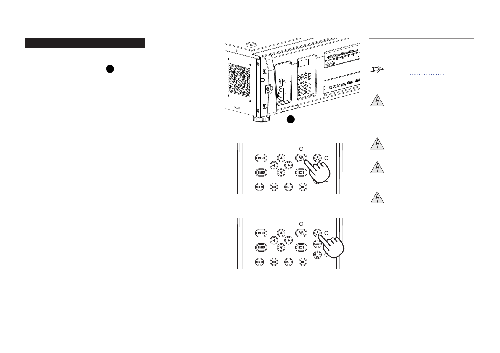
Switching the projector on
1. Make sure the power switch
1
above the AC mains inlet is in the OFF
position. Connect the power cable between the mains supply and the
projector, then turn the power switch on.
The SYSTEM status indicator lights a steady amber to show that the
projector is now in STANDBY mode.
2. (optional step) If no button is pressed within 30 seconds of the projector
entering STANDBY mode, the control panel becomes locked.
To unlock the control panel, press and hold the KEY LOCK button for one
second or longer.
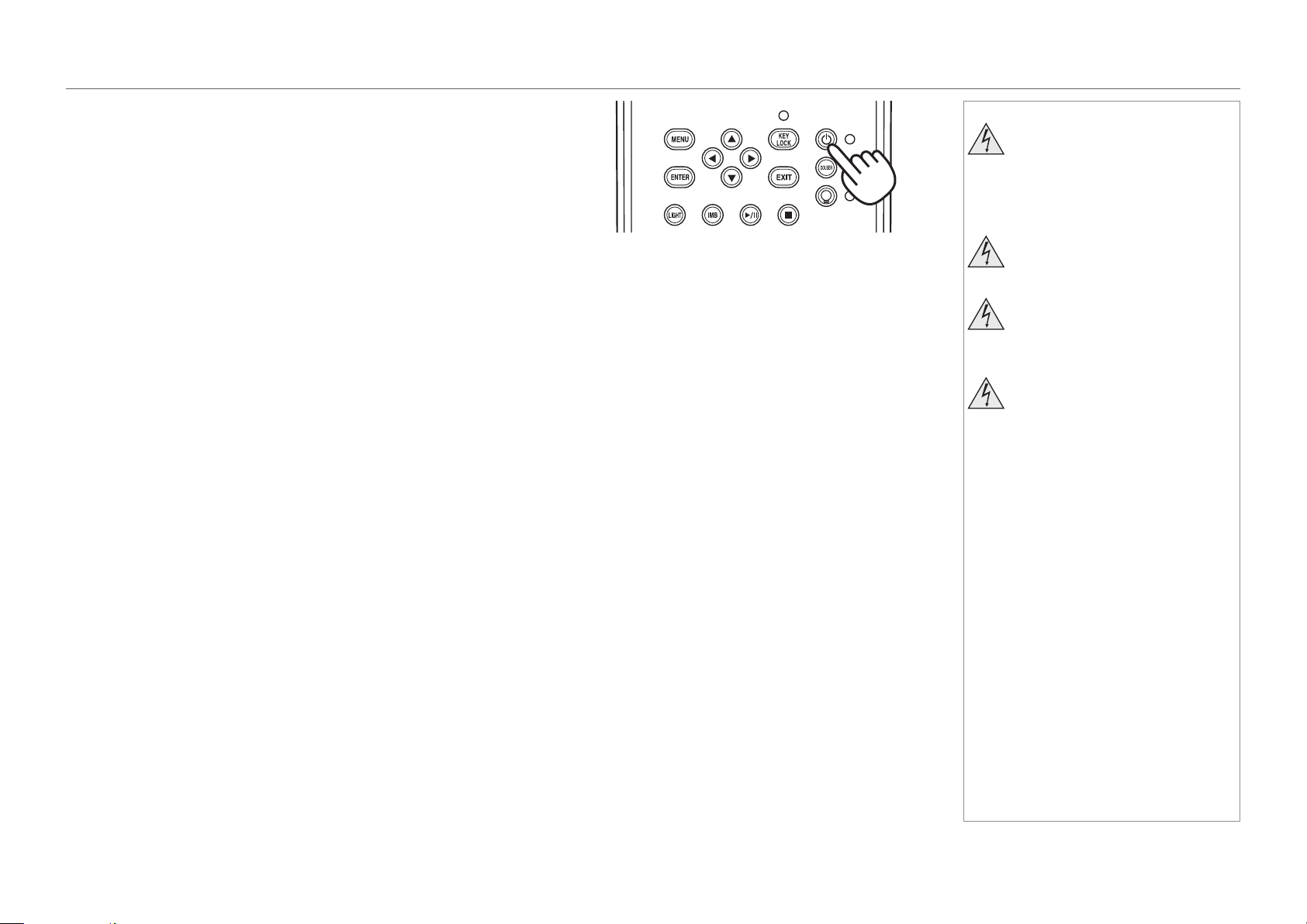
3. To switch from STANDBY to ON mode, press and hold the POWER button
for three seconds or longer.
During the startup process, the SYSTEM status indicator ashes green.
When the projector is fully switched on, the SYSTEM status indicator lights a
steady green.
1
Notes
See also Power Supply earlier in
this guide.
Do not turn off the projector from
the power switch or disconnect
the power cord while the
projector is working or cooling
down.
Use only the power cable
provided.
Ensure that the power outlet
includes a ground connection as
this equipment MUST be earthed.
Handle the power cable carefully
and avoid sharp bends. Do not
use a damaged power cable.
page 28
Model No. NP-PH1201QL
Installation and Quick-Start Guide
OPERATING THE PROJECTOR
Switching the projector off
1. Press and hold the POWER button for three seconds or longer.
The light source switches off and the projector begins cooling down. During
the cooling down process, the SYSTEM status indicator ashes amber. The
fan continues to work and a message is displayed on the LCD screen to
show that the projector is still not switched off.
When the fan switches off, the SYSTEM status indicator lights a steady
amber to indicate that the projector is now in STANDBY mode.
2. To switch the projector off completely, turn the power switch OFF.
Notes
Do not turn off the projector from
the power switch or disconnect
the power cord while the
projector is working or cooling
down.
Use only the power cable
provided.
Ensure that the power outlet
includes a ground connection as
this equipment MUST be earthed.
Handle the power cable carefully
and avoid sharp bends. Do not
use a damaged power cable.
page 29
Model No. NP-PH1201QL
Installation and Quick-Start Guide
OPERATING THE PROJECTOR
Selecting a title or test pattern
The projector arrives with titles and test
patterns already congured. If you need
to change the conguration, contact your
dealer.
Selecting a title
Connect the title you wish to display and
switch on the input source, then switch
on the projector. If necessary, unlock the
keypad.
If the title is assigned a shortcut, press the
shortcut button and the projector will begin
displaying the title.
If there is no shortcut assigned to the title:
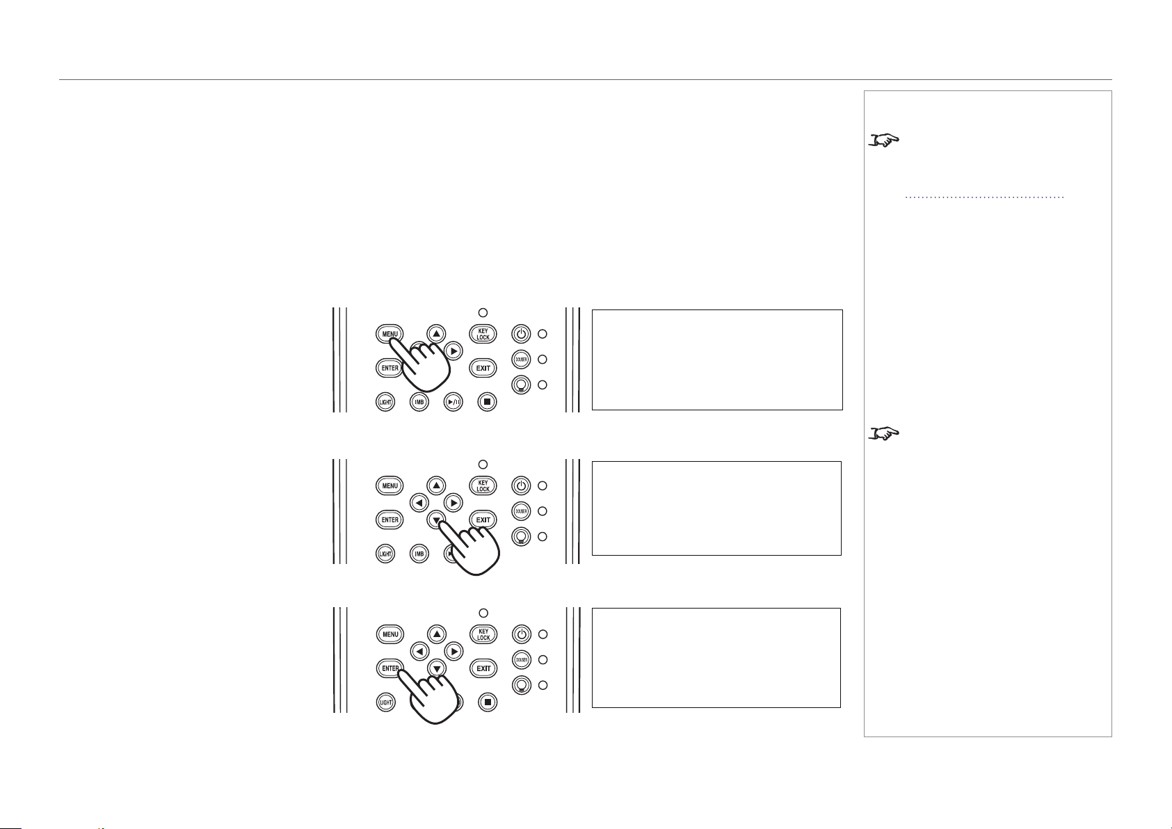
1. Press the MENU button.
2. Press the LEFT or RIGHT button to
cycle through the list of menus until Title
Select appears on the LCD screen. The
list of menus is as follows:
• Title Select
• Conguration
• (Title Setup)
• Information
• ...
3. When Title Select is displayed, press
DOWN.
4. Press LEFT or RIGHT to go through the
list of available titles until you reach the
title you wish to display.
5. Press ENTER to conrm your choice.
The projector begins displaying the title.
An asterisk mark (*) appears on the LCD
screen to indicate the current selection.
Notes
For detailed information about
switching on the projector and
unlocking the keypad, see
Switching the projector on earlier
in this guide.
Menus and menu items displayed in
parentheses can only be accessed
by service personnel.
Title Select
Title Select
Title Name
Title Select
(*)
Title Name
page 30
Model No. NP-PH1201QL
Installation and Quick-Start Guide
OPERATING THE PROJECTOR
Selecting a test pattern
Switch on the projector and, if necessary,
unlock the keypad.
If the test pattern is assigned a shortcut, press
the shortcut button and the projector will begin
displaying the test pattern.
If there is no shortcut assigned to the test
pattern:
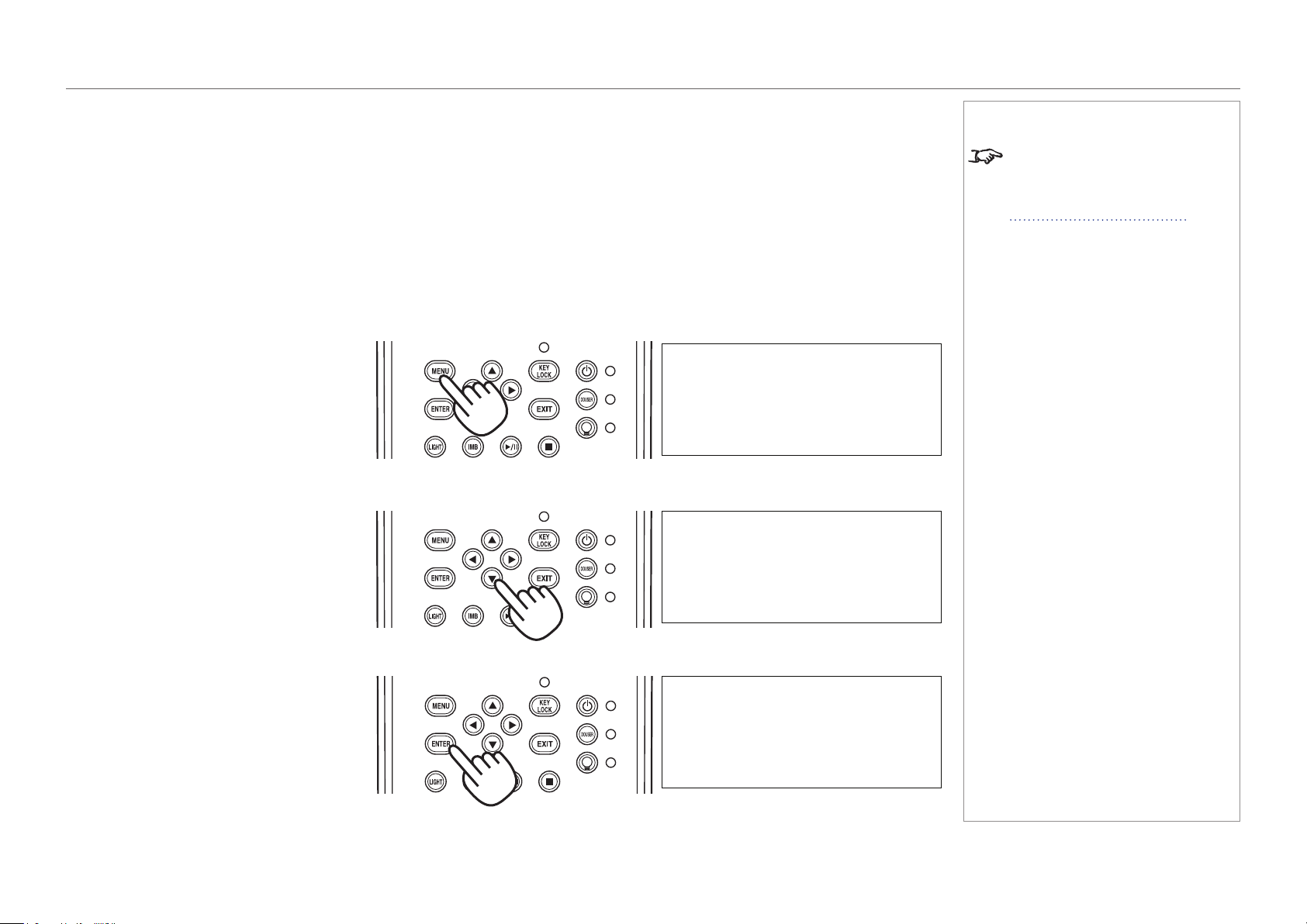
1. Press the MENU button.
2. Press the LEFT or RIGHT button to
cycle through the list of menus until Title
Select appears on the LCD screen. The
list of menus is as follows:
• Title Select
• Conguration
• (Title Setup)
• Information
• ...
3. When Title Select is displayed, press
DOWN.
4. Press LEFT or RIGHT until Title Select
is set to TEST Pattern.
5. Press DOWN again, then press LEFT or
RIGHT to cycle through the list of test
patterns.
6. When you have arrived at the test pattern
you wish to display, press ENTER to
conrm your choice. The projector begins
displaying the test pattern. An asterisk
mark (*) appears on the LCD screen to
indicate the current selection.
To cancel test pattern display, cycle through
the list again and select OFF, then press
ENTER to conrm your choice.
Title Select
Off
Title Select
(*)
TEST Pattern
Alignment
Title Select
(*)
TEST Pattern
Notes
For detailed information about
switching on the projector and
unlocking the keypad, see
Switching the projector on earlier
in this guide.

page 31
Model No. NP-PH1201QL
Installation and Quick-Start Guide
OPERATING THE PROJECTOR
Adjusting the lens
1. Press MENU.
2. Press the LEFT or RIGHT button to cycle through the list of menus until Conguration
appears on the LCD screen. The list of menus is as follows:
• Title Select
• Conguration
• (Title Setup)
• Information
• ...
3. Press DOWN to enter the Conguration menu, then press the LEFT or RIGHT button
to cycle through conguration submenus until you reach Lens Control.
Lens controls are accessed in two modes - Lens Position and Focus Zoom. Press
ENTER to switch between the two modes.
• In Lens Position mode, use the arrow buttons to shift the lens in the desired
direction.
• In Focus Zoom mode, use:
• UP and DOWN to change the focus,
• LEFT and RIGHT to change the zoom.
Notes
Lens Control
Configuration
-
Focus Zoom
• •
+ - +
Lens Position
•
Configuration

page 32
Model No. NP-PH1201QL
Installation and Quick-Start Guide
OPERATING THE PROJECTOR
Adjusting the brightness
1. Press MENU.
2. Press the LEFT or RIGHT button to cycle through the list of menus until Conguration
appears on the LCD screen. The list of menus is as follows:
• Title Select
• Conguration
• (Title Setup)
• Information
• ...
3. Press DOWN to enter the Conguration menu, then press the LEFT or RIGHT button
to cycle through conguration submenus until you reach Light Setup.
4. Use the LEFT and RIGHT arrow buttons to adjust the brightness.
Notes
100 [%] >
Light Setup
(*)
Adjust

Model No. NP-PH1201QL
Projector
PH1201QL
Connection Guide

Model No. NP-PH1201QL
Connection Guide
IN THIS GUIDE
IN THIS GUIDE
Signal Inputs ....................................................................................................... 35
SDI and DVI inputs ....................................................................................................35
3D Sync ..........................................................................................................................36
Indicators on the terminal panel ......................................................................................37
EDID on the DVI inputs .............................................................................................38
Using HDMI/DVI/DisplayPort switchers with the projector ..............................................38
Control Connections ........................................................................................ 39
page 35
Model No. NP-PH1201QL
Connection Guide
SIGNAL INPUTS
Signal Inputs
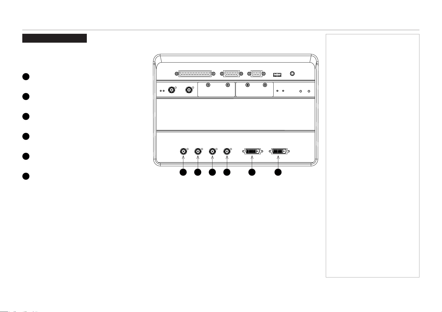
SDI and DVI inputs
The following inputs are available on the main connections
panel:
1
3G-SDI A
3G-SDI
2
3G-SDI B
3G-SDI
3
3G-SDI C
3G-SDI
4
3G-SDI D
3G-SDI
5
DVI A
DVI-D
6
DVI B
DVI-D
The SDI inputs can be used for both 3G-SDI and HD-SDI.
The four SDI inputs can be used separately with a 2K
or 1080p image, which the projector will scale to 4K, or
simultaneously, to project an image from a full 4K source.
The two DVI inputs can be used simultaneously as well, to
display native 4K resolution.
Notes
1 2 3 4 5 6
page 36
Model No. NP-PH1201QL
Connection Guide
SIGNAL INPUTS
3D Sync
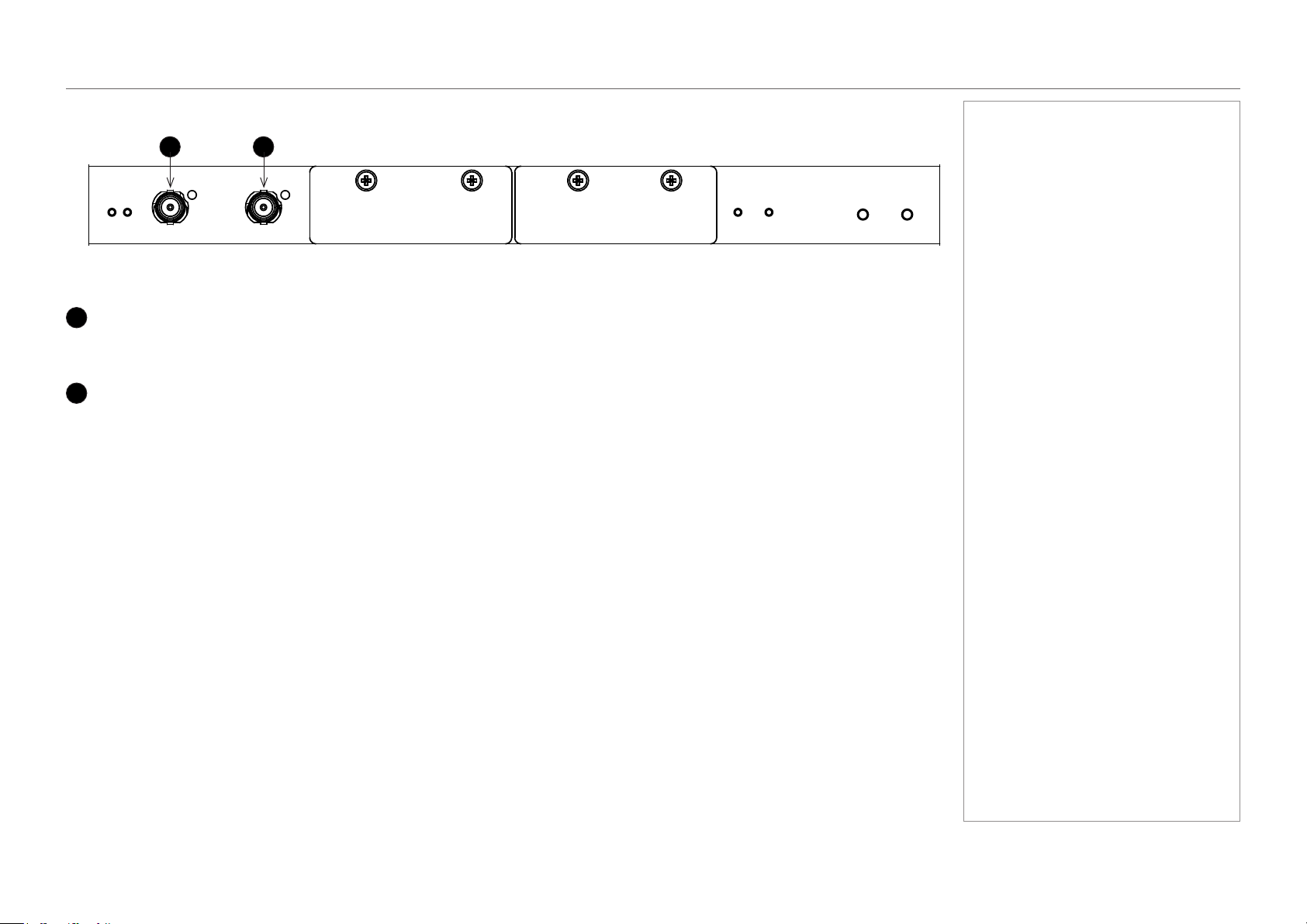
1
3D Sync In
Sync input signal
Connect the 3D sync from your graphics card or server.
2
3D Sync Out
Sync output signal
Connect this to your IR emitter or ZScreen.
Notes
Terminal panel
1 2
page 37
Model No. NP-PH1201QL
Connection Guide
SIGNAL INPUTS
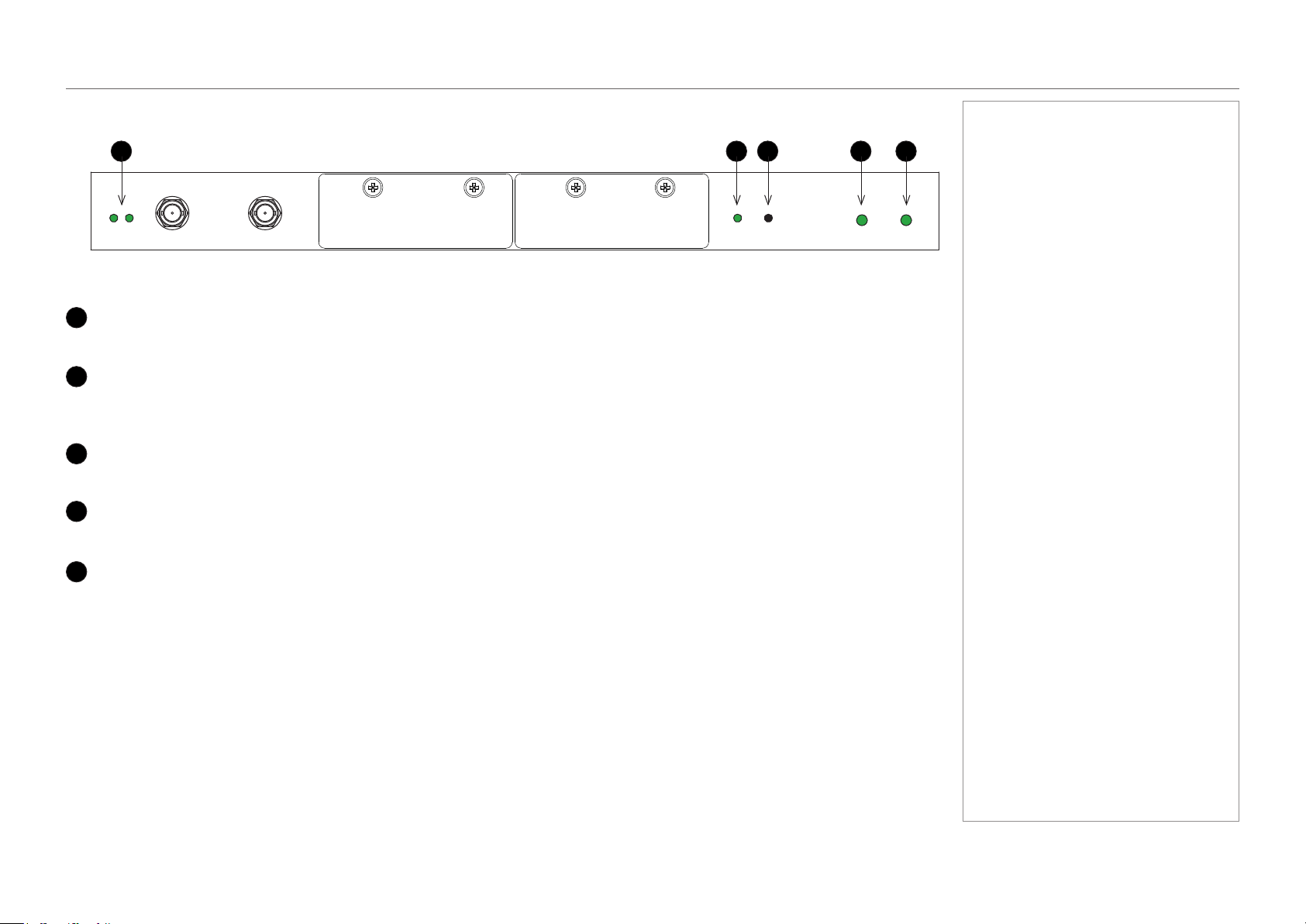
Indicators on the terminal panel
1
3D Sync In / Out
These indicators light solid green if 3D sync is present.
2
Option A
If an input on Option A board is in use, this indicator lights a solid green color.
If an input on Option A board is selected but the source is not present, the indicator ashes green.
3
Option B
This indicator is not used.
4
Power
This indicator lights a solid green color if the projector is switched on.
5
Health
This indicator ashes amber, then green, during boot up.
When the projector is switched on and fully functional, the indicator lights solid green.
Notes
Main connections panel
1 2 53 4
page 38
Model No. NP-PH1201QL
Connection Guide
SIGNAL INPUTS
EDID on the DVI inputs
If you are using a computer DVI card or another source that obeys the EDID protocol, the source will automatically congure itself to suit the
projector.
Otherwise please refer to the documentation supplied with the source to manually set the resolution to the DMD™ resolution of the projector
or the nearest suitable setting. Switch off the source, connect to the projector, then switch the source back on again.
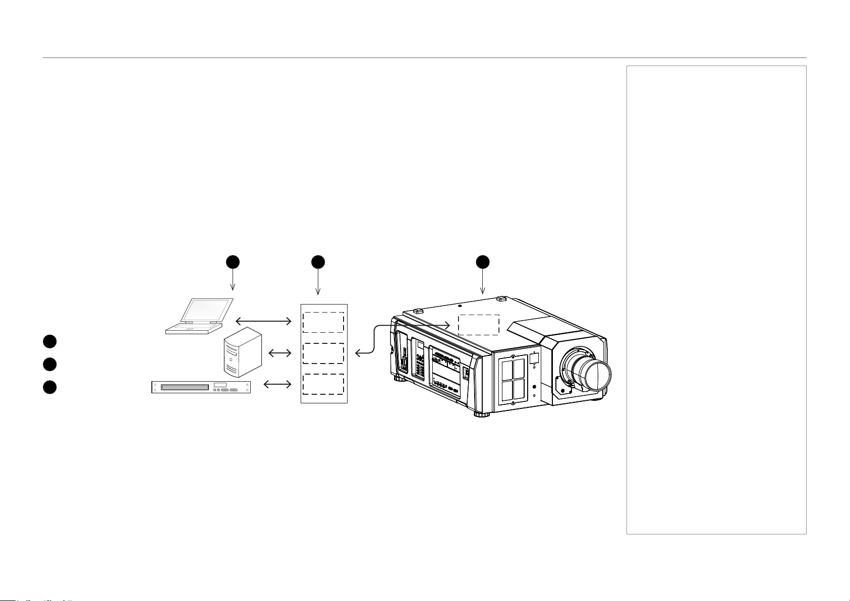
Using HDMI/DVI/DisplayPort switchers with the projector
When using a DVI source switcher with the projector, it is important to set the switcher so that it passes the projector EDID through to the
source devices. If this is not done, the projector may not be able to lock to the source or display the source correctly as its video output
timings may not be compatible with those of the projector. Sometimes this is called transparent, pass-through or clone mode. See your
switcher’s manual for information on how to set this mode.
Additionally, sources which use HDCP encryption may not display properly when connected to the projector via a switcher. Refer to the
switcher’s manual for more information.
1
Sources
2
Switcher
3
Projector
Notes
The EDIDs in the switcher should be the same as the one in the projector.
1 32
EDID
EDID
EDID
EDID
page 39
Model No. NP-PH1201QL
Connection Guide
CONTROL CONNECTIONS
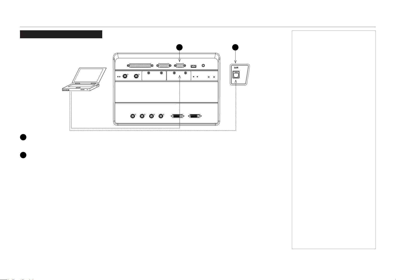
Control Connections
1
PC control terminal (RS-232)
Use this terminal when controlling the projector in serial connection from a PC.
2
LAN port (LAN)
Use this port when controlling the projector in LAN connection from a PC.
Notes
1 2

Model No. NP-PH1201QL
Connection Guide
This page is intentionally left blank.

Model No. NP-PH1201QL
Projector
PH1201QL
Operating Guide

Model No. NP-PH1201QL
Operating Guide
IN THIS GUIDE
IN THIS GUIDE
Using The Control Panel ................................................................................. 43
LCD display overview ...............................................................................................43
In STANDBY mode .........................................................................................................43
In operation .....................................................................................................................43
When showing menus .....................................................................................................44
Locking and unlocking the control panel ...............................................................45
Working with menus ................................................................................................46
Entering alphanumeric values .........................................................................................46
Using The Projector ......................................................................................... 47
Title Select menu .......................................................................................................47
Selecting a test pattern ...................................................................................................47
Congurationmenu ..................................................................................................48
Light Setup ......................................................................................................................48
Lens Control ....................................................................................................................48
Reset ...............................................................................................................................48
Information menu ......................................................................................................49
Light Output ....................................................................................................................49
Preset Button ..................................................................................................................49
Usage ..............................................................................................................................49
Error Code ......................................................................................................................49
Version ............................................................................................................................50
IP Address .......................................................................................................................51
Setup Date ......................................................................................................................51
Option Status ..................................................................................................................51
page 43
Model No. NP-PH1201QL
Operating Guide
USING THE CONTROL PANEL
Using The Control Panel
LCD display overview
In STANDBY mode
When the projector is in STANDBY mode, the following is displayed on the LCD screen.
In operation
When the projector is in operation, the following is displayed on the LCD screen.
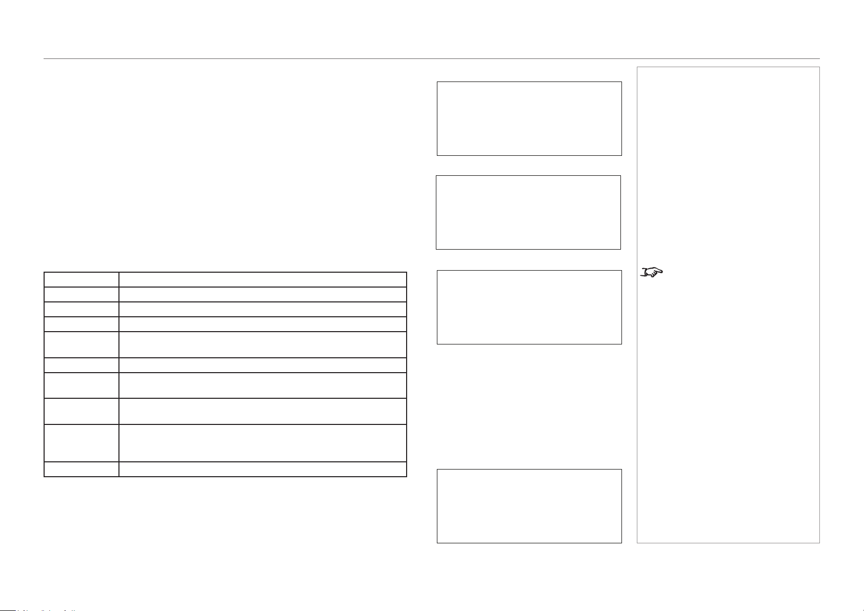
1
Hours of light source use
2
Light source output (brightness)
3
Selected title
4
Selected video input port
Notes
Standby
Light Off
3
4
2
1
Light 100H
80%
Title
292-A
page 44
Model No. NP-PH1201QL
Operating Guide
USING THE CONTROL PANEL
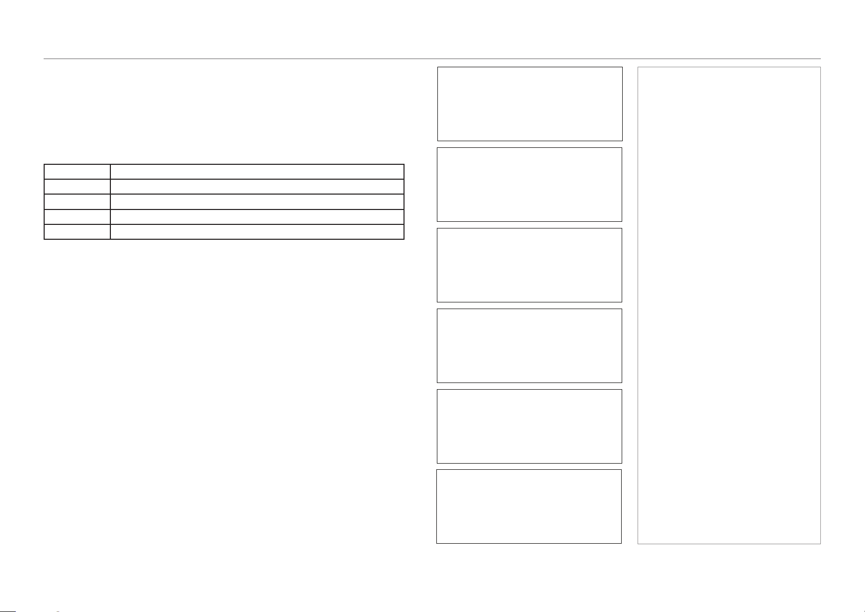
When showing menus
Typically the LCD display shows information on four lines:
1
Menu name
2
Submenu or setting name
3
An asterisk indicates the value shown below is the currently assigned value
4
Value of the setting
Notes
Alignment
Title Select
(*)
TEST Pattern
3
4
2
1
page 45
Model No. NP-PH1201QL
Operating Guide
USING THE CONTROL PANEL
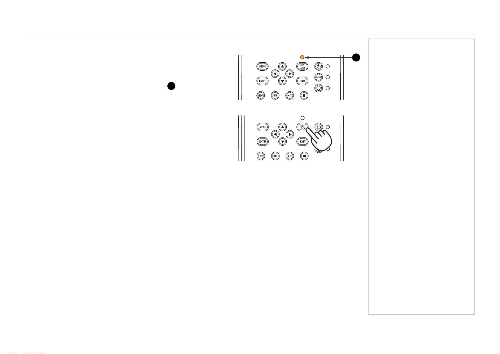
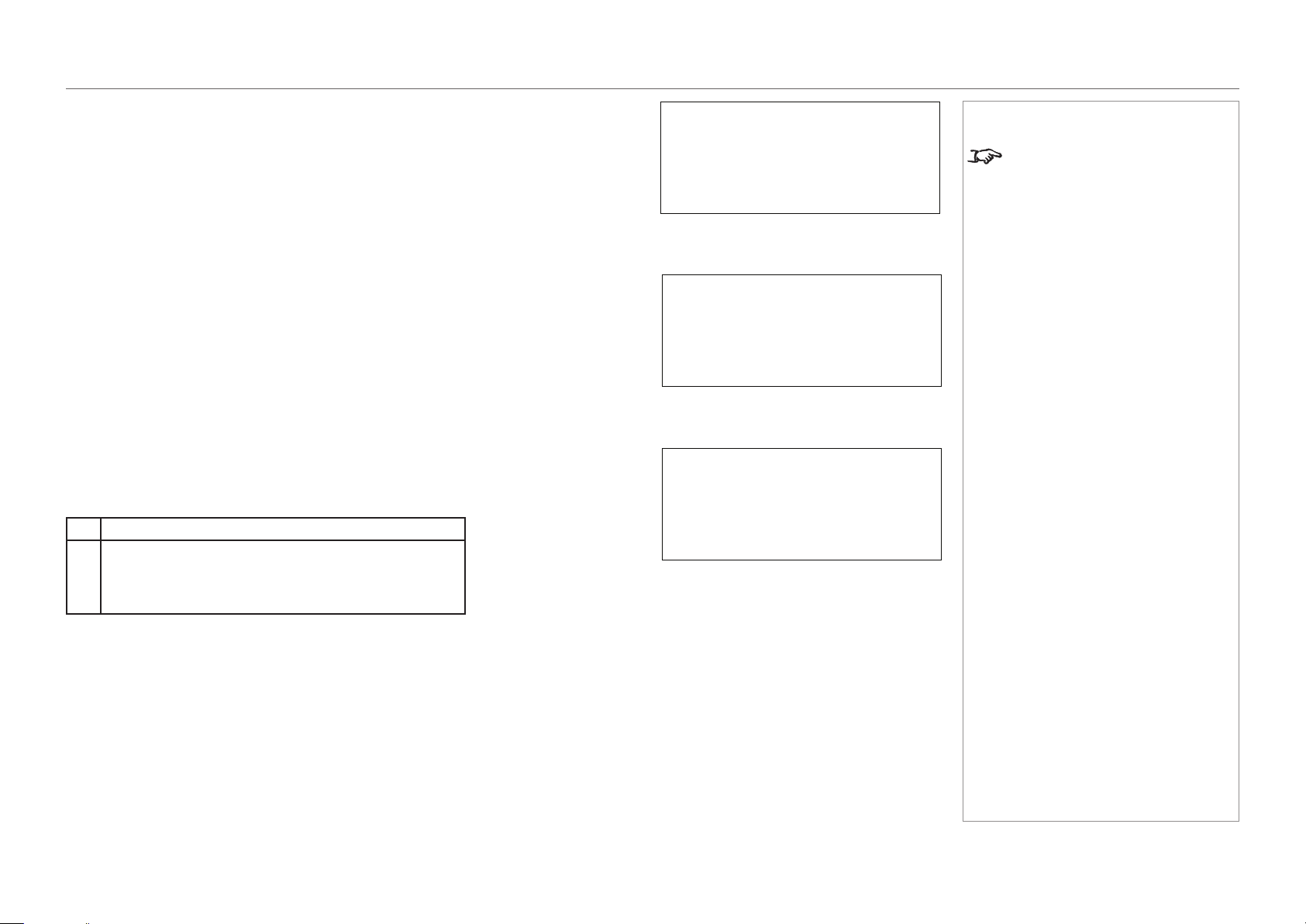
Locking and unlocking the control panel
Depending on the Auto Key Lock setting, the control panel may automatically lock
itself following a period of inactivity.
When the control panel is locked, the KEY LOCK indicator
1
lights amber.
To lock or unlock the control panel, press and hold the KEY LOCK button for one
second or longer.
1
Notes
page 46
Model No. NP-PH1201QL
Operating Guide
USING THE CONTROL PANEL
Working with menus
• To access the projector menus, press MENU.
• Navigate with the arrow buttons:
• Press the UP button to go above the current menu level.
• Press the DOWN button to go below the current menu level.
• When more items are available at the current level, go through the
list using the LEFT and RIGHT arrow buttons.
• To select an item, navigate to the item and press ENTER.
• To return to the higher level, press EXIT.
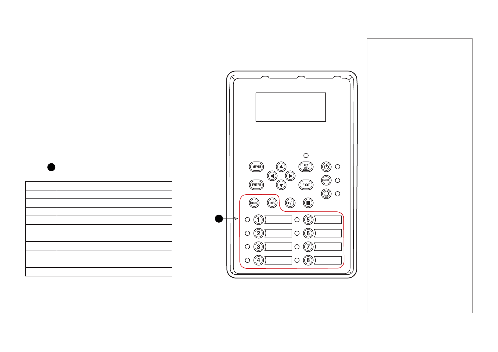
Entering alphanumeric values
Alphanumeric values are sometimes required, for example when writing the
log le to an external memory location via USB.
To enter an alphanumeric character, use the eight preset buttons, LIGHT
and IMB
1
. Each button produces multiple characters. Pressing the button
repeatedly cycles through the characters as shown in the table below.
Button Character
1
A → B → C → 1 → a → b → c → ! ...
2
D → E → F → 2 → d → e → f → “ ...
3
G → H → I → 3 → g → h → i → # ...
4
J- K → L → 4 → j → k → l → $ ...
5
M → N → O → 5 → m → n → o → % ...
6
P → Q → R → 6 → p → q → r → & ...
7
S → T → U → 7 → s → t → u → ‘ ...
8
V → W → X → 8 → v → w → x → ( ...
LIGHT
Y → Z → / → 9 → y → z → ? → ) ...
IMB
* → , → . → 0 → ; → : → + → - ...
Advance to the next position using RIGHT. Return to the previous position
using LEFT. Delete the current character value with DOWN.
Notes
1

page 47
Model No. NP-PH1201QL
Operating Guide
USING THE PROJECTOR
Using The Projector
Title Select menu
Use this menu to select a title to be projected.
The projector contains a list of up to 100 registered titles. Use this menu to select a title from the list.
To select a title:
1. Open the menu. The Title Select menu appears by default.
2. Press DOWN to access the list of available titles.
3. Navigate through the list using the LEFT and RIGHT arrow buttons.
4. Press ENTER to select a title.
Provided the selected title is connected to a signal, the projection should begin immediately.
Selecting a test pattern
1. Navigate to the TEST Pattern title on the list.
2. Press DOWN to access the list of test patterns.
3. Press ENTER to select a test pattern.
The selected test pattern should appear on the screen immediately.
Notes
If the title you want to display is
assigned a preset button, you can
skip the procedure on this page by
simply pressing the preset button.
Up to 16 presets can be assigned
on the projector. Presets 1 to
8 are recalled by pressing the
corresponding preset button. To
recall preset 9 to 16, press and hold
the UP arrow button, then press the
corresponding number button. If,
for example, the preset you wish to
recall is 9, the corresponding keypad
combination is UP + 1. For preset
10, the combination is UP + 2, etc.

page 48
Model No. NP-PH1201QL
Operating Guide
USING THE PROJECTOR
Conguration menu
Press DOWN to access various projector settings.
Light Setup
Use this menu to adjust the light output.
Lens Control
Lens controls are accessed in two modes - Lens Position and Focus Zoom. Press ENTER
to switch between the two modes.
• In Lens Position mode, use the arrow buttons to shift the lens in the desired direction.
• In Focus Zoom mode, use:
• UP and DOWN to change the focus,
• LEFT and RIGHT to change the zoom.
Reset
This is used to reset the air lter usage time.
Press the ENTER button, then select Yes in the displayed conrmation screen, and then
press the ENTER button to reset the air lter usage time.
Notes
Lens Control
Configuration
-
Focus Zoom
• •
+ - +
Lens Position
•
Configuration
100 [%] >
Light Setup
(*)
Adjust
Reset
Filter Usage
Reset
page 49
Model No. NP-PH1201QL
Operating Guide
USING THE PROJECTOR
Information menu
Displays information relating to the light source, the usage time of the projector, the version
information and error codes.
Light Output
Displays the value of the Light Output setting as percentage of the maximum light source
output.
Preset Button
Shows the titles assigned to the sixteen presets stored in the projector’s memory.
Usage
Displays information related to the projector usage, such as the usage time of the projector,
light source, air lters, and fan, and information about the light source replacement cycle.
Projector
Displays the usage time of the projector.
Filter
Displays the usage time of the air lters.
Filter Cleaning
Displays the time elapsed since the previous lter cleaning.
Fan
Displays the usage time of the fan.
Light
Display of the usage time of the light source and the value that is
displayed is the amount of usage time remaining (approximate).
Light Strike
Displays the number of times the light source has been turned on.
Phosphor
Display of the usage time of the phosphor and the value that is
displayed is the amount of usage time remaining (approximate).
Diffuser
Display of the usage time of the diffuser and the value that is
displayed is the amount of usage time remaining (approximate).
LCS
Display of the usage time of LCS (Liquid Cooling System) and
the value that is displayed is the amount of usage time remaining
(approximate).
Douser Count
Displays the number of times the douser has been used.
Error Code
Displays the error code when an error occurs.
When multiple errors occur, you can display them by pressing the LEFT/RIGHT buttons.
Notes
The remaining amount displayed in
Light/Phosphor/Diffuser/LCS is
calculated from the current usage
time with the unused state as 100%
and time to replace as 0%.
< 63 [%] >
Information
Light Output
Preset Button
PresetButton1
Title No.8
( Logo )
Usage
Projector
( 0 [H] )
Error Code
No Error
( --- )
page 50
Model No. NP-PH1201QL
Operating Guide
USING THE PROJECTOR
Version
Displays version information about the projector, optional boards, and IMB
System
Displays the version information of the projector.
BIOS
Displays the BIOS version of the projector.
Firmware
Displays the rmware version of the projector.
Data
Displays the data version of the projector.
Serial No.
Displays the serial number of the projector.
Model
Displays the model name of the projector.
SIB
Displays the model name and version information about the signal input board (SIB). When the
projector is in standby mode, the version information displays “---”.
IMB
This item is not available in the current conguration.
Slave
Displays the slave rmware version of the projector.
Laser
Displays the laser light source rmware version of the projector.
Notes
Version
Information
System
Data
( Ver1.00-A
)
Version
SIB
NC-80DS
< 2.0 >
Version
IMB
< NOT USED >
Version
Slave
< MM01 >
Version
Laser
< 05 >
page 51
Model No. NP-PH1201QL
Operating Guide
USING THE PROJECTOR
IP Address
Displays the IP address set up in the projector.
Setup Date
Displays the date when the projector was set up (the starting date of the warranty period).
Option Status
Displays the link status of the device mounted in slot A (media block, signal input board) on
the projector. The device name is displayed in ( ) when the projector is in standby or when
connection to the device cannot be conrmed.
B Not Available: Slot B is not available in this projector.
A Displays the link status of the device in slot A.
• NC-80DS: Signal input board (NC-DS03)
• No Board: No device mounted
IP Address
<System *>
( 192.168.10.10)
Notes
The projector has a default IP
address. Access the IP Address
page to connect the IP address of
the projector to your network. You
can later change the IP address
using a special software application.
Information
Setup Date
< 2015/03/03 >
Information
Option Status
B: Not Avail…
<
A: NC-80DS
>

Model No. NP-PH1201QL
Operating Guide
This page is intentionally left blank.

Model No. NP-PH1201QL
Projector
PH1201QL
Reference Guide

Model No. NP-PH1201QL
Reference Guide
IN THIS GUIDE
IN THIS GUIDE
The DMD™ ........................................................................................................... 55
Choosing A Lens ................................................................................................ 57
Screen Requirements ...................................................................................... 58
Fitting the image to the DMD™ ................................................................................58
Diagonal screen sizes ...............................................................................................59
Fitting the image to the screen ................................................................................60
Positioning the screen and projector ......................................................................61
Positioning The Image .................................................................................... 62
Aspect Ratios Explained ................................................................................ 64
Appendix A: Lens Part Numbers .................................................................. 65
Appendix B: Supported Signal Input Modes ............................................ 66
Supported 4K signals - Option board .....................................................................66
Screen allocation of Option board input signals ..............................................................67
Appendix C: Menu Map .................................................................................... 68
TITLE SELECT ...........................................................................................................68
CONFIGURATION ......................................................................................................68
(TITLE SETUP) ...........................................................................................................68
INFORMATION ...........................................................................................................69
Appendix D: Wiring Details ............................................................................ 70
Signal inputs - option board ....................................................................................70
DVI ..................................................................................................................................70
3G-SDI In ........................................................................................................................71
Control connections .................................................................................................72
LAN .................................................................................................................................72
RS232 .............................................................................................................................72
3D Sync IN and 3D Sync OUT ........................................................................................72
Technical Specications ................................................................................ 73
Models ........................................................................................................................73
Inputs and outputs ....................................................................................................74
Bandwidth ..................................................................................................................74
Remote control and keypad .....................................................................................74
Automation control ...................................................................................................74
Color temperature .....................................................................................................74
Lenses ........................................................................................................................75
Lens mount ................................................................................................................75
Mechanical mounting ...............................................................................................75
Orientation .................................................................................................................75
Electricalandphysicalspecications ....................................................................76
Safety & EMC regulations ........................................................................................76
CAD drawings ............................................................................................................77
NEC Contacts ..................................................................................................... 78
page 55
Model No. NP-PH1201QL
Reference Guide
THE DMD™
The DMD™
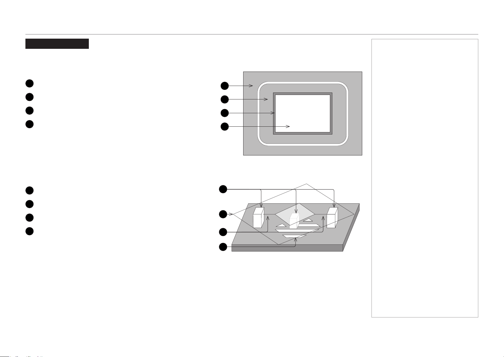
A DMD™ (Digital Micromirror Device™) is a true digital light modulator which utilises an array of approximately 8.8 million moving aluminium
mirrors, with each one representing a pixel in the nal projected image. The outermost micromirrors in the array remain inactive (pond of
mirrors) and are not used in constructing the image.
1
Casing
2
Light shield
3
Pond of mirrors
4
Array
Each mirror element is suspended over address electrodes by a torsion hinge between two posts.
1
Support posts
2
Mirror element
3
Torsion hinges
4
Offset address electrode
Notes
DMD™
2
3
4
1
Mirror element with tilt mechanism
2
1
3
4
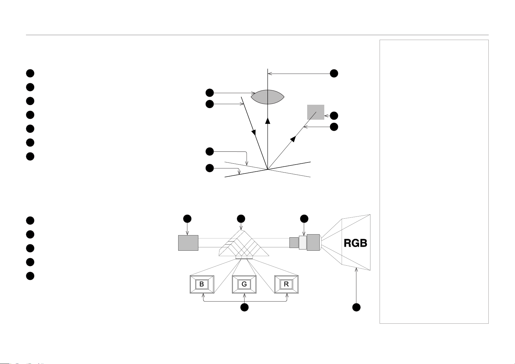
page 56
Model No. NP-PH1201QL
Reference Guide
THE DMD™
Depending on the voltage polarity applied, each mirror will either tilt to the left to produce a bright pixel or to the right for a dark pixel. When
light is applied to the complete DMD™, only the light redirected from a mirror tilting to the left is projected.
1
Projection lens
2
Incoming light from the illumination module
3
Mirror element tilted to the right
4
Mirror element tilted to the left
5
Reectedlight,lefttilt
6
Light dump
7
Reectedlight,righttilt
The projector optically lters white light from the illumination module into its constituent red, green and blue. Each color illuminates a separate
DMD™ whose modulated output is then recombined with the other two to form the projected full color image.
1
Illumination module
2
Opticallteringoflightintored,greenandblue
3
Projection lens
4
DMD™ devices
5
Full color image displayed on screen
Notes
Light ow
1
2
3
4
5
6
7
white light RGB light
blue
light
green
light
red
light
1 2 3
4 5
Filtering process

page 57
Model No. NP-PH1201QL
Reference Guide
CHOOSING A LENS
Choosing A Lens
A number of lenses are available. Which lens you choose depends on the screen size, image aspect ratio, throw distance and light output.
The following table shows all available lenses in order of their throw ratios:
Throw ratios Lens extension
0.91 : 1 Fixed lens 278 mm
1.13 - 1.66 : 1 zoom lens 270 mm
1.30 - 1.85 : 1 zoom lens 225 mm
1.45 - 2.17 : 1 zoom lens 222 mm
1.63 - 2.71 : 1 zoom lens 134 mm
1.95 - 3.26 : 1 zoom lens 137 mm
2.71 - 3.89 : 1 zoom lens 190 mm
3.7 - 5.3 : 1 zoom lens 262 mm
4.8 - 7.4 : 1 zoom lens 308 mm
Notes
For information about individual lens
part numbers, see Appendix A at
the end of this document.
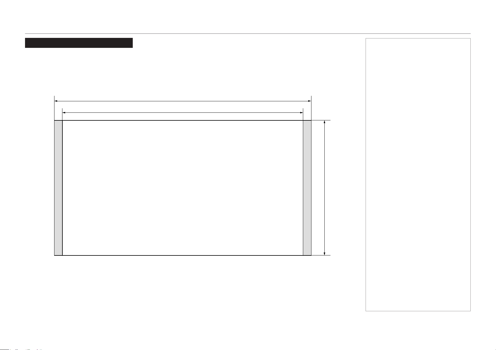
page 58
Model No. NP-PH1201QL
Reference Guide
SCREEN REQUIREMENTS
Screen Requirements
Fitting the image to the DMD™
The projector supports 4K and Ultra HD formats and is able to achieve 2K and 1080p via frame doubling.
2K and frame doubled 1080p will not utilize the full width of the DMD™, resulting in pillarboxing, as shown in the illustration.
true 4K, UHD ( also pixel doubled 2K, 1080p) = 2160 pixels
true 4K (also pixel doubled 2K) = 4096 pixels
UHD (also pixel doubled 1080p) = 3840 pixels
Notes
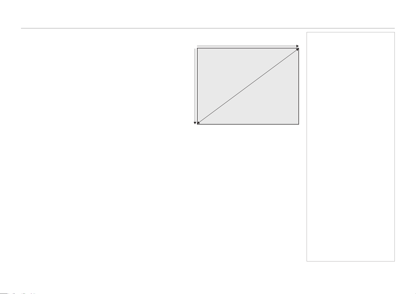
page 59
Model No. NP-PH1201QL
Reference Guide
SCREEN REQUIREMENTS
Diagonal screen sizes
Screen sizes are sometimes specied by their diagonal size (D). When dealing
with large screens and projection distances at different aspect ratios, it is more
convenient to measure screen width (W) and height (H).
The example calculations below show how to convert diagonal sizes into width and
height, at various aspect ratios.
TRUE 4K (approximately 1.9 : 1)
W = D x 0.88 H = D x 0.47
UHD (approximately 1.78 : 1)
W = D x 0.87 H = D x 0.49
Notes
D = diagonal
W = width
H = height
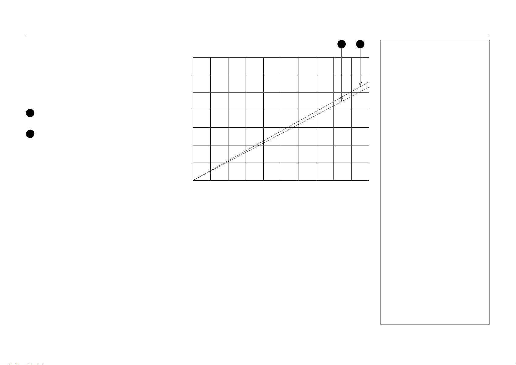
page 60
Model No. NP-PH1201QL
Reference Guide
SCREEN REQUIREMENTS
Fitting the image to the screen
It is important that your screen is of sufcient height and
width to display images at all the aspect ratios you are
planning to use.
Use the conversion chart to check that you are able
to display the full image on your screen. If you have
insufcient height or width, you will have to reduce the
overall image size in order to display the full image on
your screen.
3
4K / 2K (1.9:1)
W = H x 1.9, H = W x 0.53
4
UHD / 1080p (16:9 = 1.78:1)
W = H x 1.78, H = W x 0.56
Notes
Screen width
1 2 3 4 5 6 7 8 9 10
Screen height
1
2
3
4
5
6
7
1 2
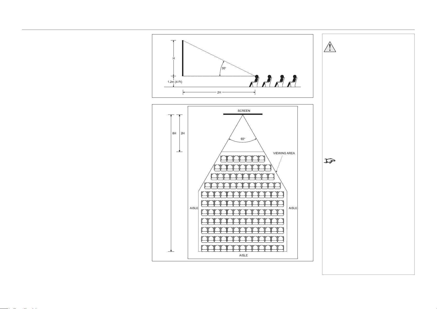
page 61
Model No. NP-PH1201QL
Reference Guide
SCREEN REQUIREMENTS
Positioning the screen and projector
For optimum viewing, the screen should be a at surface
perpendicular to the oor. The bottom of the screen should
be 1.2 m (4 feet) above the oor and the front row of the
audience should not have to look up more than 30° to see
the top of the screen.
The distance between the front row of the audience and
the screen should be at least twice the screen height and
the distance between the back row and the screen should
be a maximum of 8 times the screen height. The screen
viewing area should be within a 60° range from the face of
the screen.
Notes
The projector should be installed
as close to the power outlet as
possible.
The power connection should be
easily accessible, so that it can
be disconnected in an emergency.
Ensure that there is at least 30
cm (12 in) of space between the
ventilation outlets and any wall,
and 10 cm (4 in) on all other
sides.
Do not install the projector close
to anything that might be affected
by its operational heat, for
instance, polystyrene ceiling tiles,
curtains etc.
The image can be ipped for rear
projection and displayed without the
need for extra mirrors or equipment.
However, you must ensure that
there is sufcient distance behind
the screen for the projector to be
correctly located.
Rear installation is generally more
complicated and advice should be
sought from your local dealer before
attempting it.
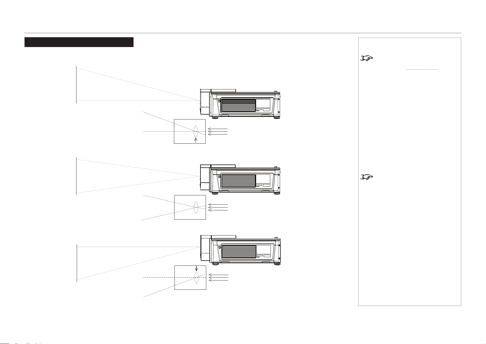
page 62
Model No. NP-PH1201QL
Reference Guide
POSITIONING THE IMAGE
Positioning The Image
The normal position for the projector is at the centre of the screen. However, you can set the projector above or below the centre, or to one side,
and adjust the image using the Lens shift feature (known as rising and falling front) to maintain a geometrically correct image.
Notes
For more information on shifting
the lens, see Lens control in the
Operating Guide.
Whenever possible, position the
projector so that the lens is centered
for the highest quality image.
Shifting the lens up (rising front)
Centered lens
Shifting the lens down (falling front)
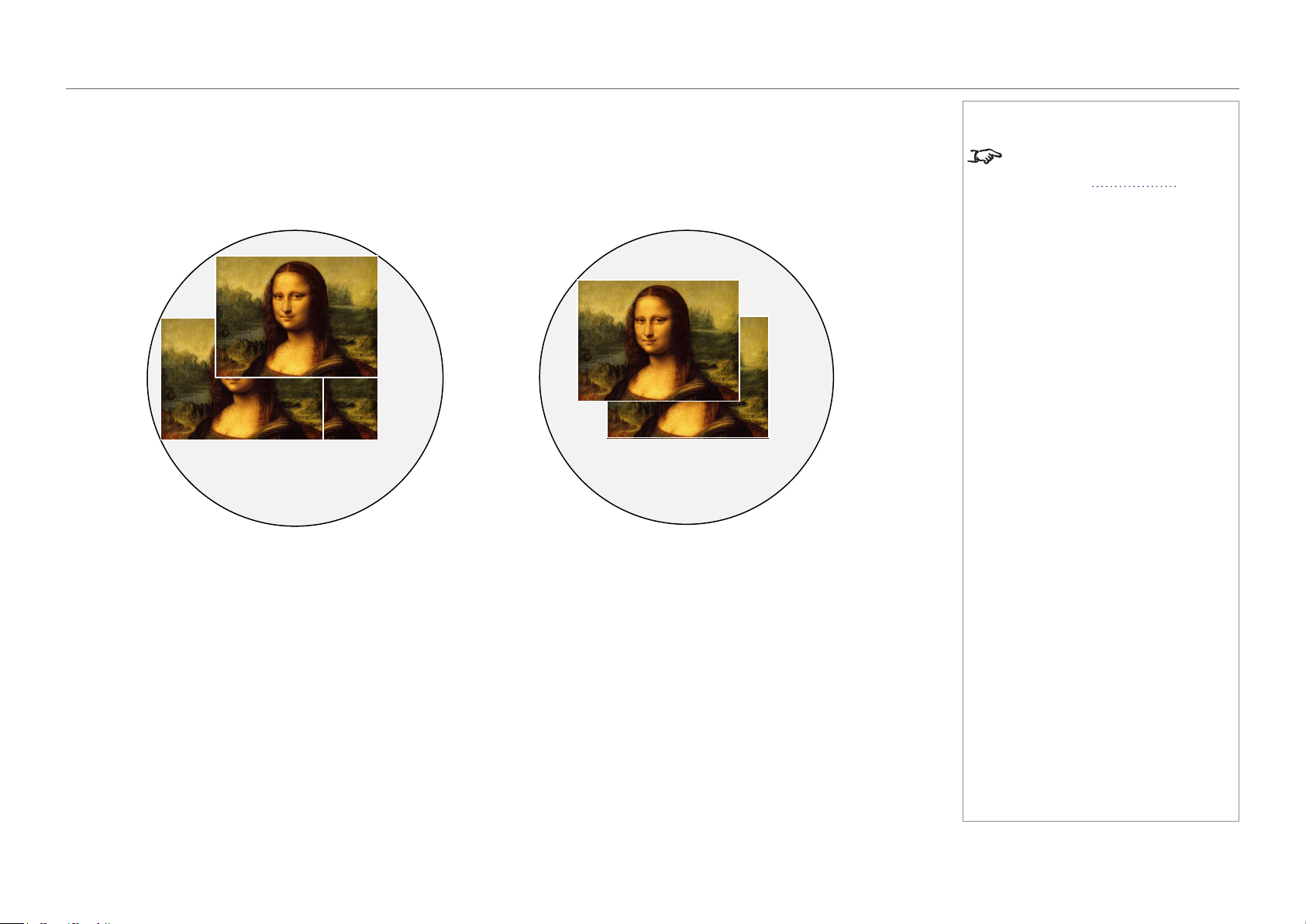
page 63
Model No. NP-PH1201QL
Reference Guide
POSITIONING THE IMAGE
Any single adjustment outside the ranges specied on the following page may result in an unacceptable level of distortion, particularly at the
corners of the image, due to the image passing through the periphery of the lens optics.
If the lens is to be shifted in two directions combined, the maximum range without distortion will be somewhat less, as can be seen in the
illustrations below.
Notes
For more information on shifting
the lens, see Lens control in the
Operating Guide.
Full horizontal or vertical shift Combined shift is reduced

page 64
Model No. NP-PH1201QL
Reference Guide
ASPECT RATIOS EXPLAINED
Aspect Ratios Explained
The appearance of a projected image on the screen depends on:
the DMD™ resolution, which is 4K with a 4096 x 2160 resolution, corresponding to an aspect ratio of 256:135, or approximately 1.9:1.
the aspect ratio of the input signal, which is 1.9:1 for 4K and 2K images, or 1.78:1 for UHD or 1080p images.
2K and 1080p are automatically scaled by the projector to ll the height of the DMD™.
The 4K and 2K resolutions have a slightly wider aspect ratio. UHD and scaled 1080p do not ll the width of the DMD™, so they appear
centered, with pillarboxing at the sides, as shown in the illustration.
Notes
Pillarboxing on UHD and 1080p images

page 65
Model No. NP-PH1201QL
Reference Guide
APPENDIX A: LENS PART NUMBERS
Appendix A: Lens Part Numbers
Lens name Part number Throw ratios Lens extension
L2K-10F1 1160360 0.91 : 1 Fixed lens 278 mm
NC-50LS12Z 01165191 1.13 - 1.66 : 1 zoom lens 270 mm
NC-50LS14Z 01165165 1.30 - 1.85 : 1 zoom lens 225 mm
NC-50LS16Z 01165163 1.45 - 2.17 : 1 zoom lens 222 mm
NC-50LS18Z 01165164 1.63 - 2.71 : 1 zoom lens 134 mm
NC-50LS21Z 01165166 1.95 - 3.26 : 1 zoom lens 137 mm
L2K-30ZM 01165070 2.71 - 3.89 : 1 zoom lens 190 mm
L2K-43ZM1 01160361 3.7 - 5.3 : 1 zoom lens 262 mm
L2K-55ZM1 01160362 4.8 - 7.4 : 1 zoom lens 308 mm
Notes
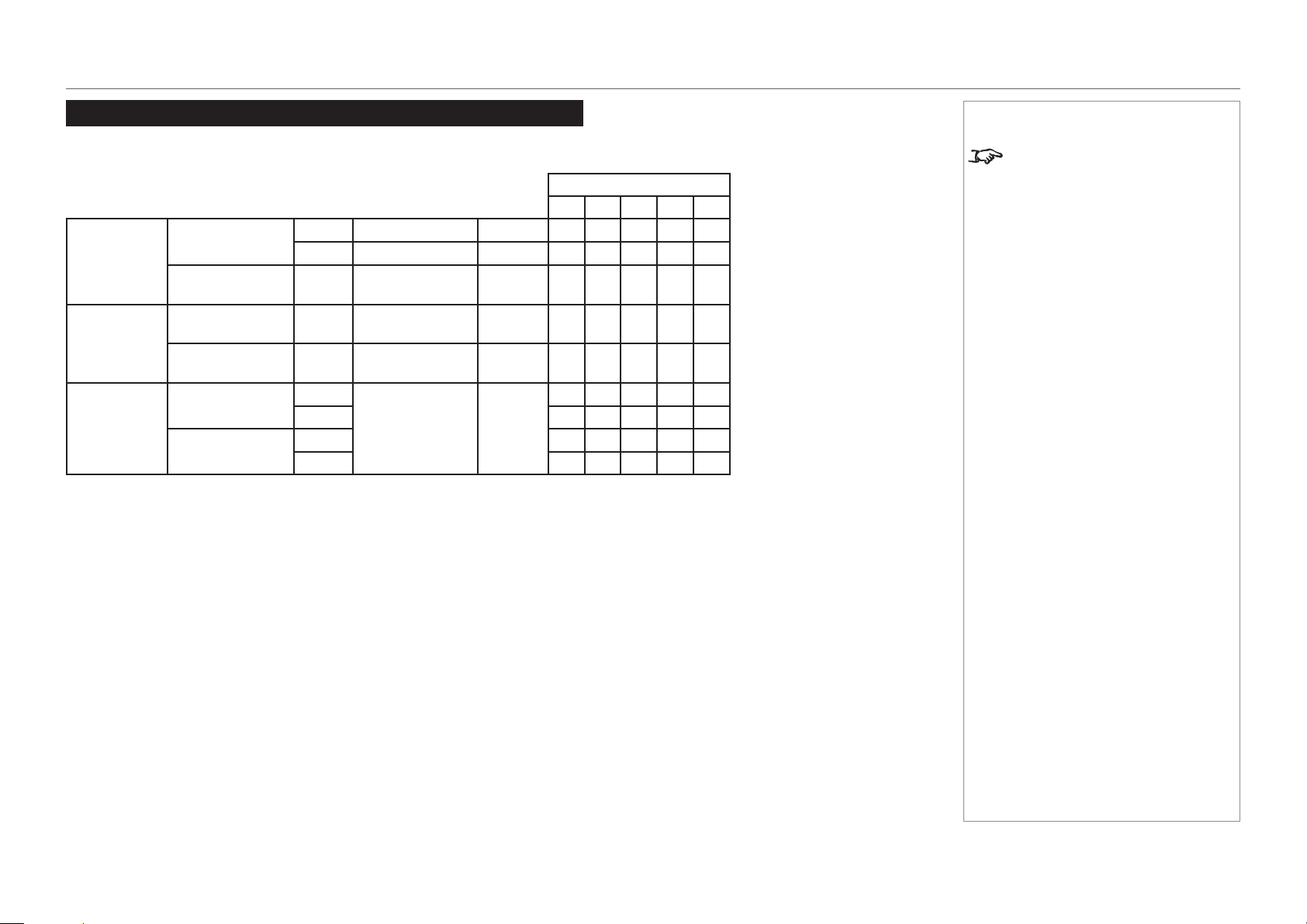
page 66
Model No. NP-PH1201QL
Reference Guide
APPENDIX B: SUPPORTED SIGNAL INPUT MODES
Appendix B: Supported Signal Input Modes
Supported 4K signals - Option board
V Frequency
24 25 30 50 60
HD-SDI Quad
3840x2160
(1920x1080 4port)
p YCbC r4:2:2 10 bit
ü ü ü
P sF YCbC r4:2:2 10 bit
ü ü ü
4096x2160
(1920x1080 4port)
p YCbC r4:2:2 10 bit
ü ü ü
3G-SDI Quad
3840x2160
(1920x1080 4port)
p RGB/YCbC r4:4:4 10/12 bit
ü ü ü ü ü
4096x2160
(1920x1080 4port)
p RGB/YCbC r4:4:4 10/12 bit
ü ü ü ü ü
DVI Twin
3840x2160
(1920x1080 4port)
p
RGB 8 bit
ü ü ü
P sF
4096x2160
(1920x1080 4port)
p
ü ü ü
P sF
Notes
3G-SDI is Level A only.
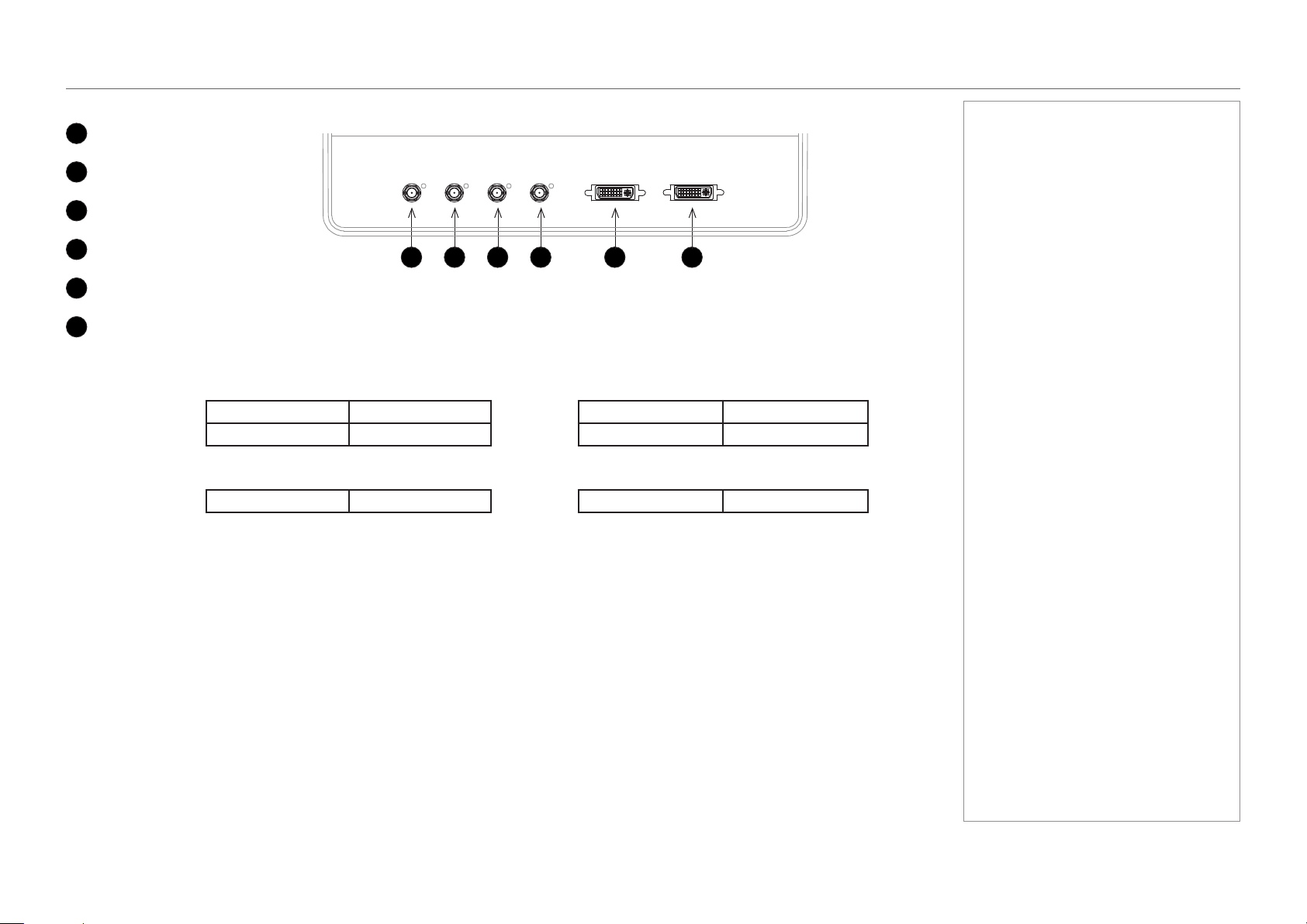
page 67
Model No. NP-PH1201QL
Reference Guide
APPENDIX B: SUPPORTED SIGNAL INPUT MODES
Screen allocation of Option board input signals
1
3G-SDI A
2
3G-SDI B
3
3G-SDI C
4
3G-SDI D
5
DVI A
6
DVI B
3840 4096
SDI Quad
2160
SDI A: 1920 x 1080 SDI B: 1920 x 1080
2160
SDI A: 2048 x 1080 SDI B: 2048 x 1080
SDI C: 1920 x 1080 SDI D: 1920 x 1080 SDI C: 2048 x 1080 SDI D: 2048 x 1080
3840 4096
DVI Twin 2160 DVI A: 1920 x 2160 DVI B: 1920 x 2160 2160 DVI A: 2048 x 2160 DVI B: 2048 x 2160
Notes
1 2 3 4 5 6
page 68
Model No. NP-PH1201QL
Reference Guide
APPENDIX C: MENU MAP
Appendix C: Menu Map
Menu Sub Menus Description
TITLE SELECT
Title Memory Name Selects the title of the signal to be projected.
Test Pattern Selects a test pattern to be projected.
CONFIGURATION
Light Setup
Adjust Adjusts the light source brightness (output).
Lens Control
Lens Position Adjusts the position of the projected image.
Focus Zoom Adjusts the size and focus of the projected image.
Reset
(Factory Default) Returns the settings to their default values.
Selects between preset buttons and titles only, LAN settings and all
settings.
Filter Usage Initializes the usage time of the air lter.
Filter Cleaning Initializes the lter cleaning time.
(Fan Usage) Initializes the usage time of the fan.
(Light Usage) Initializes the usage time of the light source.
(Phosphor) Initializes the usage time of the phosphor.
(Diffuser) Initializes the usage time of the diffuser.
(LCS) Initializes the usage time of the liquid cooling system.
(Douser Count) Resets the number of times the douser has been used.
(Setup) This menu is inaccessible from the control panel.
(Installation)
(Memory)
(TITLE SETUP)
Notes
Some of the information in this menu
map is summarised. See the actual
menu on the projector for full details.
Menus and menu items displayed
in parentheses cannot be accessed
from the control panel.
To access such items, you need to
connect the projector to a computer
running a specially designed
application. The software will require
special login credentials.

page 69
Model No. NP-PH1201QL
Reference Guide
APPENDIX C: MENU MAP
Menu Sub Menus Description
INFORMATION
Light Output Displays the light source output setting.
Lens Type Displays the lens type setting.
Preset Button
Preset Button 1 - 16 Displays the titles assigned to the preset buttons (<1> to <8>).
Usage Displays information related to projector usage.
Error Code Displays any currently occurring error.
Version
System Displays model name and version information about the projector.
SIB Displays model and version of the signal input board (SIB).
Slave Displays the slave rmware version of the projector.
Laser Displays the laser light source rmware version of the projector.
IP Address
System Displays the IP address of the projector.
Setup Date Displays the date when the projector was set up (starting date of the
warranty period).
Option Status Displays the link status of the device mounted in slot A and projector
Notes
Some of the information in this menu
map is summarised. See the actual
menu on the projector for full details.
Menus and menu items displayed in
parentheses can only be accessed
by service personnel.
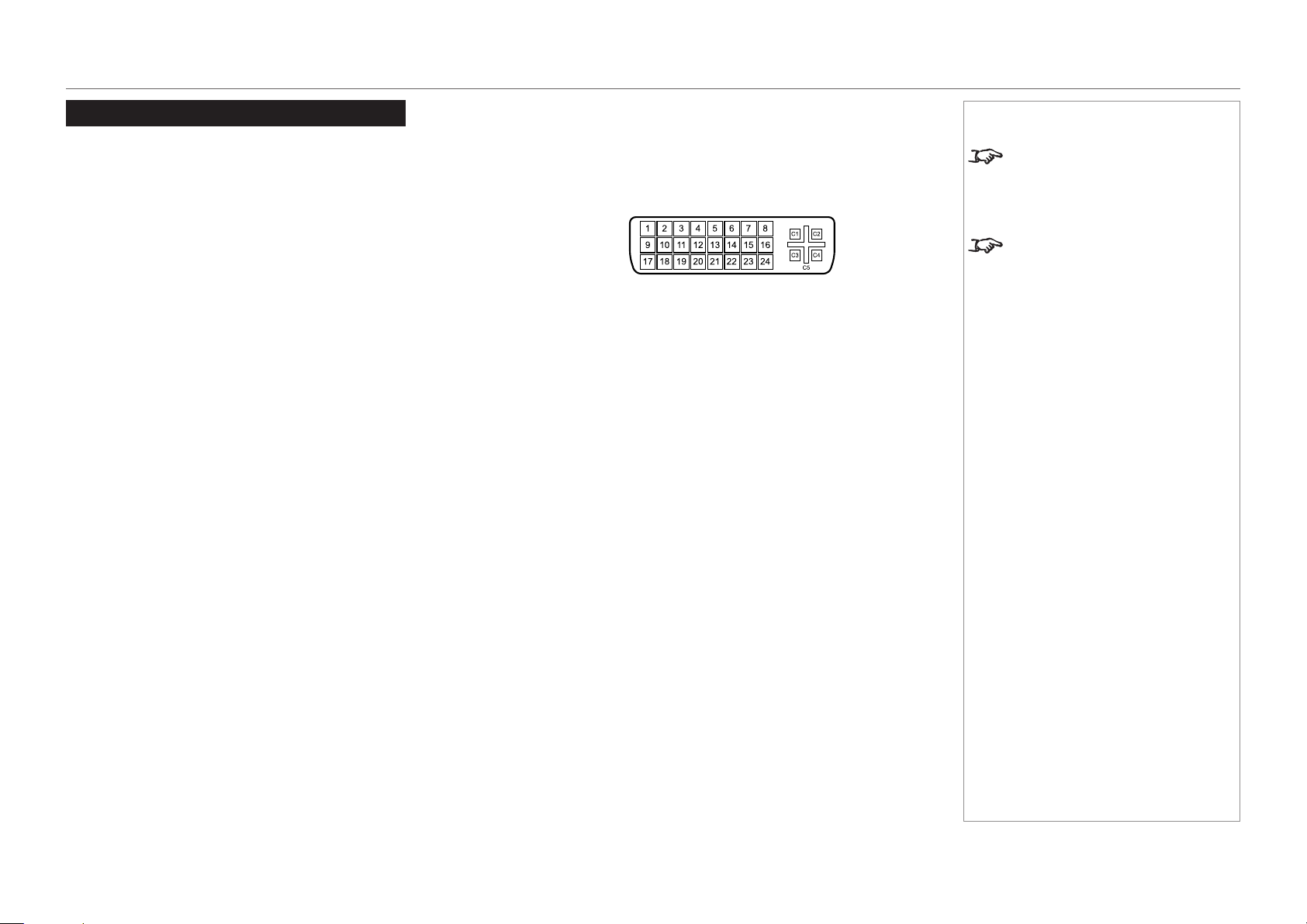
page 70
Model No. NP-PH1201QL
Reference Guide
APPENDIX D: WIRING DETAILS
Appendix D: Wiring Details
Signal inputs - option board
DVI
24 way D-type connector
Pin 1 TMDS data 2− Digital red− (link 1)
Pin 2 TMDS data 2+ Digital red+ (link 1)
Pin 3 TMDS data 2/4 shield
Pin 4 TMDS data 4− Digital green− (link 2)
Pin 5 TMDS data 4+ Digital green+ (link 2)
Pin 6 DDC clock
Pin 7 DDC data
Pin 8 Analog vertical sync
Pin 9 TMDS data 1− Digital green− (link 1)
Pin 10 TMDS data 1+ Digital green+ (link 1)
Pin 11 TMDS data 1/3 shield
Pin 12 TMDS data 3- Digital blue− (link 2)
Pin 13 TMDS data 3+ Digital blue+ (link 2)
Pin 14 +5 V Power for monitor when in standby
Pin 15 Ground Return for pin 14 and analog sync
Pin 16 Hot plug detect
Pin 17 TMDS data 0− Digital blue− (link 1) and digital sync
Pin 18 TMDS data 0+ Digital blue+ (link 1) and digital sync
Pin 19 TMDS data 0/5 shield
Pin 20 TMDS data 5− Digital red− (link 2)
Pin 21 TMDS data 5+ Digital red+ (link 2)
Pin 22 TMDS clock shield
Pin 23 TMDS clock+ Digital clock+ (links 1 and 2)
Pin 24 TMDS clock− Digital clock− (links 1 and 2)
C1 Analog red
C2 Analog green
C3 Analog blue
C4 Analog horizontal sync
C5 Analog ground Return for R, G, and B signals
Notes
The default hardware conguration
does not include an option board,
which can be ordered separately.
High-bandwidth Digital Content
Protection (HDCP) is supported on
this input.
DVI: pin view of female connector

page 71
Model No. NP-PH1201QL
Reference Guide
APPENDIX D: WIRING DETAILS
3G-SDI In
75 ohm BNC
Notes
3G-SDI connector
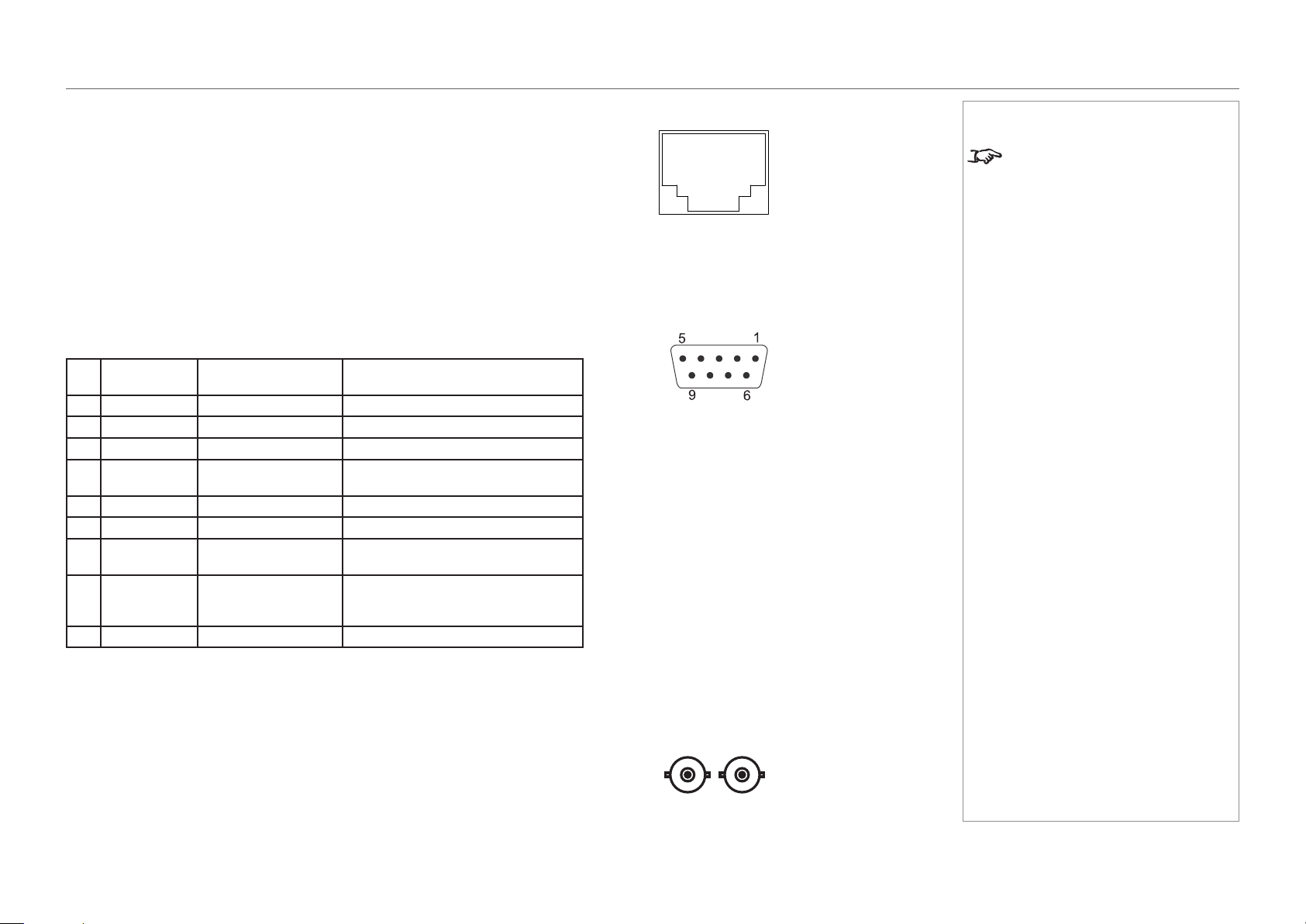
page 72
Model No. NP-PH1201QL
Reference Guide
APPENDIX D: WIRING DETAILS
Control connections
LAN
RJ45 socket
RS232
9 way D-type connector
Pin
No.
RS-232C
Signal Name
Functions as RS-232C Projector Connector Operation
1 CD Carrier detection Not used (N.C.)
2 RXD Reception data Data transmission to an external device
3 TXD Transmission data Data reception from an external device
4 DTR Data Terminal ready
(Note)
Connection to 6 pins
5 GND Signal GND Signal GND
6 DSR Data set ready (Note) Connection to 4 pins
7 RTS Transmission request SYSTEM: Hi-Z (Not used)
CINEMA: Hi-Z (Used)
8 CTS Transmission available SYSTEM: Fixed at -6.5 V (Not used)
CINEMA: ±10.5 V (Used: Depends on
communication status)
9 RI Ring indicator Not used (N.C.)
3D Sync IN and 3D Sync OUT
75 ohm BNC
Notes
Only one remote connection (RS232
or LAN) should be used at any one
time.
Update port
RS232:
pin view of female connector
pin view of female connector

page 73
Model No. NP-PH1201QL
Reference Guide
TECHNICAL SPECIFICATIONS
Technical Specications
Digital Projection reserves the right to change product specications without prior notice.
Models
The specications on these pages refer to the following projector:
Series name
NP-PH1201QL
Color system: 3-chip DLP®
Display type: 3 x 1.38” DarkChip™ DMD™
DMD™specication(native):4096 x 2160 pixels, +/- 12° tilt angle
Fast transit pixels for smooth grayscale and improved contrast.
Notes
page 74
Model No. NP-PH1201QL
Reference Guide
TECHNICAL SPECIFICATIONS
Inputs and outputs
Type Connector Qty
Video & Computer
3G-SDI BNC 4
DVI-D DVI-D 2
Communication & Control
3D Sync Out BNC 1
3D Sync In BNC 1
LAN RJ45 1
RS232 9-pin D-Sub 1
Wired Remote In 3.5 mm Stereo Jack 1
Service Port USB Type A 1
Bandwidth
N/A
Remote control and keypad
• PC control
• On-board keypad with LCD screen
Automation control
• RS232
• LAN
Color temperature
• User selectable via TCGD
Notes
The default hardware conguration
does not include an option board,
which can be ordered separately.
3G-SDI signals are very high
speed digital signals which require
better quality coaxial cable than
conventional analogue video. The
data rate is 3 Gigabits per second.
In choosing cable length and
connectors for any installation the
frequency response loss in decibels
should be proportional to √f, from 1
MHz, to 3 GHz.
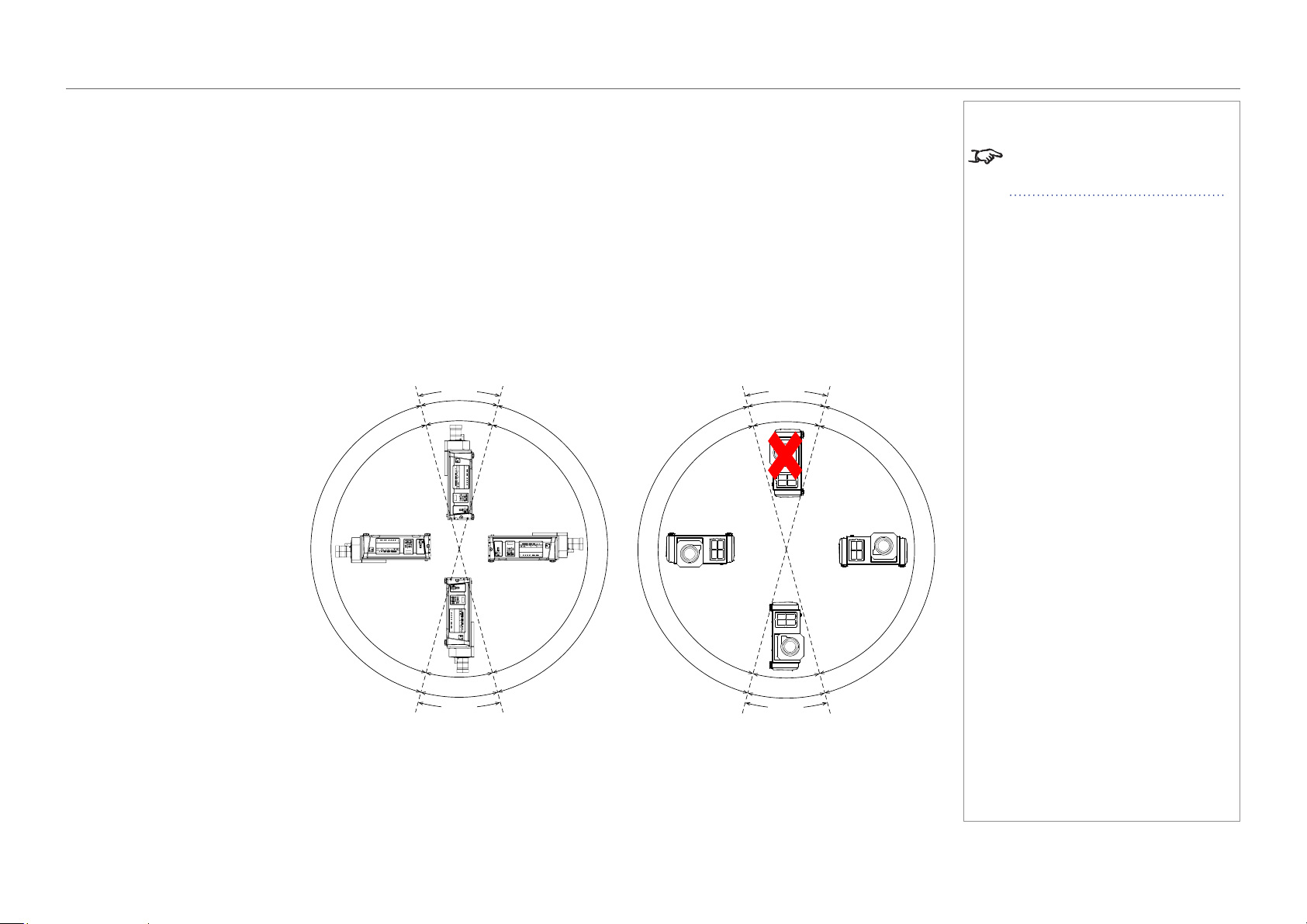
page 75
Model No. NP-PH1201QL
Reference Guide
TECHNICAL SPECIFICATIONS
Lenses
Detailed information about available lenses can be found in Appendix A: Lens Part Numbers.
Lens mount
• Motorised shift, zoom and focus. Intelligent Lens Memory with user-denable preset positions.
Mechanical mounting
• Front/Rear Table
• Front/Rear Ceiling
• Adjustable Front/Rear Feet
Orientation
• Table Top or Inverted:
Yes
• Pointing Up:
Yes, with operating
temperature 0-30°C
• Pointing Down:
Yes, with operating
temperature 0-30°C
• Roll (Portrait):
Yes, with inputs pointing
upward only and with operating
temperature 0-30°C
Notes
Information on lenses in this guide:
• Appendix A: Lens Part Numbers
- detailed descriptions of available
lenses.
Pitch
0-30°C
0-30°C
0
-
3
5
°
C
0
-
3
5
°
C
±15°
±15°
Roll
n
o
t
a
l
l
o
w
e
d
0-30°C
0
-
3
5
°
C
0
-
3
5
°
C
±15°
±15°

page 76
Model No. NP-PH1201QL
Reference Guide
TECHNICAL SPECIFICATIONS
Electrical and physical specications
• Power requirements 200-240 VAC, 50-60 Hz (single phase)
• Power Consumption 1600 W
• Thermal Dissipation 5027 BTU/hr
• Fan Noise 48 dBA
• Operating Temperature 0°C to 35°C (32 to 95F)
• Operating Temperature
(Portrait Mode)
0°C to 30°C (32 to 86F)
• Storage Temperature -10°C to 50°C (14 to 122F)
• Operating Humidity 20% to 80% non-condensing
• Weight 67 kg (148 lb)
• Dimensions H: 32.5 cm W: 70 cm L: 93.5 cm
H: 12.8 in W: 27.56 in L: 36.8 in
Safety & EMC regulations
• CE, FCC Class A, UL
Notes
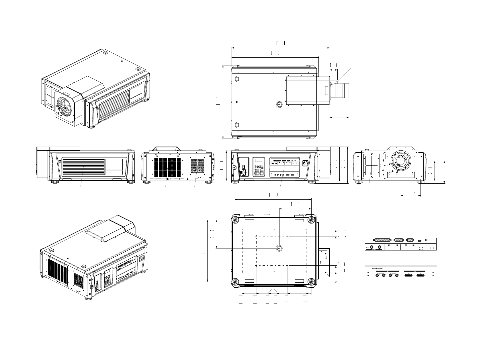
page 77
Model No. NP-PH1201QL
Reference Guide
TECHNICAL SPECIFICATIONS
CAD drawings
12.8
325
11.3
288
13.8
350
DETAIL VIEW A
7.5
191
8.5
216
7.4
187
AIR IN
AIR IN
AIR OUT
AIR OUT
2.9
74
32.7
830
36.8
935
27.5
700
LENS EXT
MOTOR GEARBOX COVER
LENS EXTENSION MEASURED FROM FRONT FACE
28.5
725
23.2
590
12.0
306
10.7
271
0
1.9
50
8.8
225
14.7
375
20.6
525
26.0
660
0
3.7
95
6.1
155
17.1
435
19.5
495
14.0
355
THREADED FIXINGS
12 0FF M6 X 12
DETAIL VIEW A (1 : 2)
IF IN DOUBT, ASK.
POWER
HEALTH
GP I/O
3D
RS-232
USB
REMOTE
IN OUT
IN OUT
A
B

page 78
Model No. NP-PH1201QL
Reference Guide
NEC CONTACTS
NEC Contacts
In Europe
NEC Display Solutions Europe GmbH
Address: Landshuter Allee 12-14
D-80637 München, Germany
Telephone: +49 89 99699 0
Email: [email protected]
In North America
NEC Display Solutions of America, Inc.
Address: 500 Park Boulevard, Suite 1100
Itasca, Illinois
60143, U.S.A.
Telephone: +1 800 836 0655
In Oceania
Australia
AWA Limited.
Address: 151 Arthur Street
Homebush West NSW 2140 Australia
Customer Call Centre
Telephone: 0297647777
Email Address: [email protected]
New Zealand
Visual Group Ltd.
Address: 28 Walls Road Penrose Auckland
New Zealand
Telephone: 095250740
Email Address: [email protected]
In South America
Brazil
Videocorp Brasil
Address: Avenida Conselheiro Rodrigues Alves Nro. 820 / Sala 15 - 2°
Andar - Vila Mariana
São Paulo - SP - Brasil
CEP 04014-002
Telefone: + 55-11-2924.2910 / + 55-11-2924.2911
Notes
In Asia
NEC Display Solutions, Ltd.
Address: 686-1, Nishioi, Oi-Machi, Ashigarakami-Gun, Kanagawa 258-8533,
Japan
Telephone: +81 465 85 2369
NEC Solutions (China) Co.,Ltd.
Address: Rm 1903, Shining Building,35 Xueyuan Rd, Haidian District Beijing
100191, P.R.C.
Telephone: +8610 59342706
NEC Hong Kong Ltd.
Address: 25/F.,The Metropolis Tower,10 Metropolis Drive, Hunghom, Kowloon,
Hong Kong
Telephone: +852 2369 0335
NEC Taiwan Ltd.
Address: 7F, No.167, SEC.2, Nan King East Road, Taipei, Taiwan, R.O.C.
Telephone: +886 2 8500 1710
NEC Asia Paci c Pte Ltd.
Address: 401 Commonwealth Drive, #07-02, Haw Par Technocentre,
Singapore 149598
Telephone: +65 6 799 6188
NEC Corporation of Malaysia Sdn. Bhd.
Address: 33rd Floor, Menara TA One, 22, Jalan P. Ramlee, 50250 Kuala
Lumpur, Malaysia
Telephone: +6 03 2178 3600 (ISDN)

Model No. NP-PH1201QL User Manual© NEC Display Solutions, Ltd. 2015