1
Español p. 19
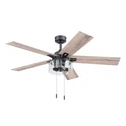
SARATOGA II
CEILING FAN
ITEM #3415245
MODEL #L1903-MW
Serial Number
Purchase Date
Questions, problems, missing parts? Before returning to your retailer, call our customer
service department at 888-251-1003, 8 a.m. - 8 p.m., EST, Monday - Sunday. You could
also contact us at [email protected] or visit www.lowespartsplus.com.
SM20629
ATTACH YOUR RECEIPT HERE
Harbor Breeze
®
and logo design are
trademarks or registered trademarks of
LF, LLC. All rights reserved.

2
TABLE OF CONTENTS
Package Contents...............................................................................................................
Hardware Contents.............................................................................................................
Safety Information...............................................................................................................
Preparation .........................................................................................................................
Initial Installation Instructions ....................................................................................................
Standard/Angle-Mounting Instructions.................................................................................
Wiring Instructions ..............................................................................................................
Final Installation Instructions ....................................................................................................
Operating Instructions ........................................................................................................
Care and Maintenance .......................................................................................................
Troubleshooting...................................................................................................................
Limited Lifetime Warranty....................................................................................................
Replacement Part List .........................................................................................................
3
4
4
5
6
7
9
10
14
15
16
17
FCC Warning.......................................................................................................................
17
18
3
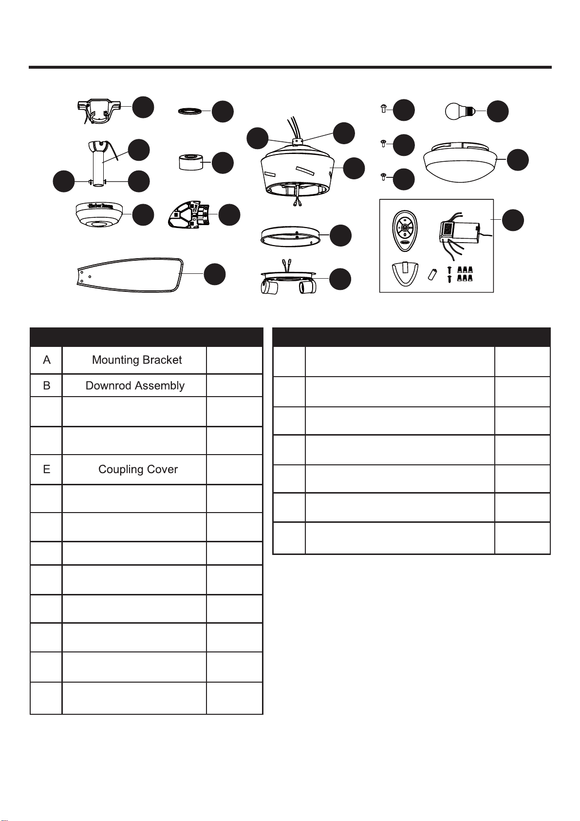
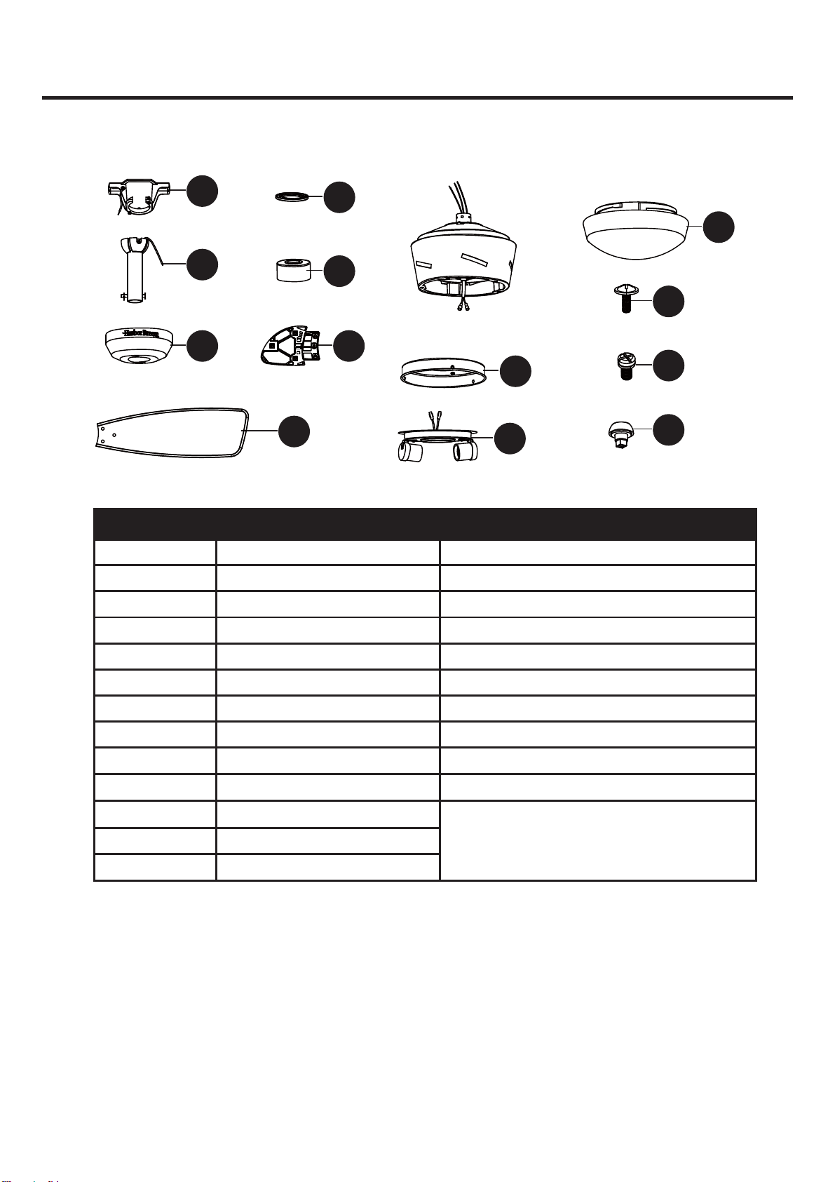
PACKAGE CONTENTS
PART DESCRIPTION QUANTITY PART DESCRIPTION QUANTITY
1
1
C Canopy 1
Coupling
(preassembled on Motor Housing (F))
1
D
Canopy Cover
1
Mounting Bracket Screw
(preassembled on Mounting Bracket (A))
2
1
1
F Motor Housing 1
Hairpin Clip (preassembled
on Downrod Assembly (B)
2
G Blade Arm 5
Coupling Screw
(preassembled on Coupling (Q))
H Blade 5
ISw
itch Housing 1
Mounting Screw
(preassembled on Motor Housing (F))
3
J Light Kit 1
Switch Housing Screw
(preassembled on Switch Housing (I))
3
K Glass Bowl 1
L LED Light Bulb 2
M Remote Unit 1
Q
R
O
1
Clevis Pin (Preassembled on
Downrod Assembly (B)
N
P
S
T
A
D
L
K
M
Q
E
F
P
I
J
H
B
NO
C G
R
T
S
4
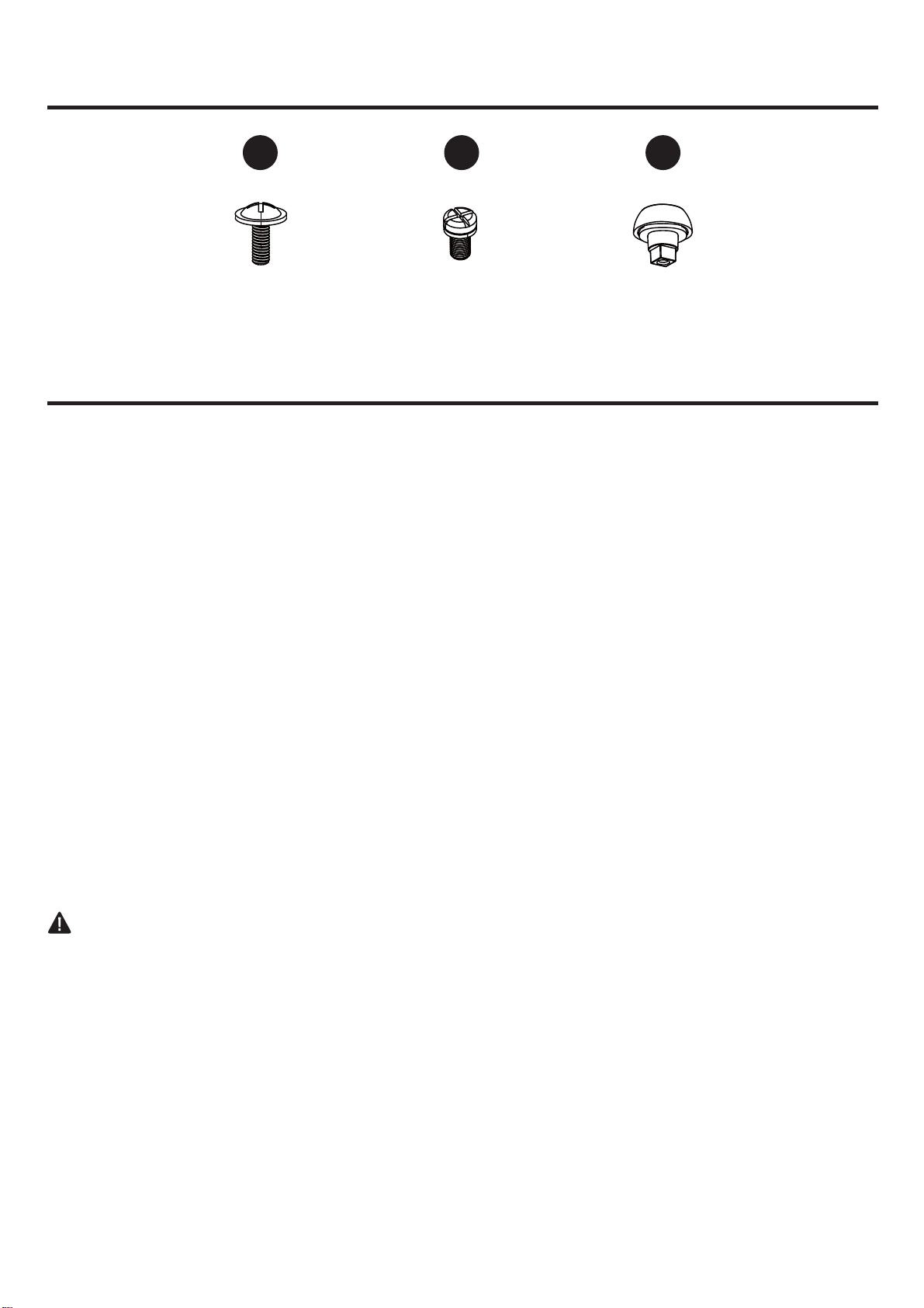
HARDWARE CONTENTS
SAFETY INFORMATION
(not shown actual size)
AA BB CC
READ AND SAVE THESE INSTRUCTIONS
Please read and understand this entire manual before attempting to assemble, operate or install the product.
. All electrical connections must comply with local codes, ordinances or the National Electric Code (NEC).
Contact your municipal building department to inquire about your local codes, permits and/or inspections.
. Turn off electricity at main fuse box (or circuit breaker box) before beginning installation by removing fuse
or by switching off circuit breaker.
. Do not connect this fixture to an electrical system that does not provide a means for equipment grounding.
Never use a fixture in a two-wire system that is not grounded.
. If you are not sure your lighting system has a grounding means, do not attempt to install this fixture. Contact
a qualified, licensed electrician for information regarding proper grounding methods as required by the local
electrical code in your area.
. Make sure the installation site you choose allows a minimum clearance of 7 ft. from the blades to the floor
and at least 30 in. from the ends of the blades to any obstruction.
. If a dimmer control switch is used with this fixture, obtain professional advice to determine the correct type
and electrical rating required.
. The lighting fixture must be positioned so there is at least 1.64 ft. between the bulb and any illuminated
surface.
. For supply connections, if the conductor of a fan is identified as a grounded conductor, then it should be
connected to a grounded conductor power supply. If the conductor of a fan is identified as an ungrounded
conductor, then it should be connected to an ungrounded conductor power supply. If the conductor of a fan
is identified for equipment grounding, then it should be connected to an equipment-grounding conductor.
. Installing a fixture into an electrical system without a proper grounding means could allow metal parts of the
fixture to carry electrical currents. If any of the fixture wires, wire connections or splices are broken, cut or
loose during the mounting or normal operation of the fixture, under such conditon, anyone coming in contact
with the fixture is subject to electrical shock, which could cause serious injury or death.
. Connection of the bare or green fixture ground wire to the black or white house wires may allow metal parts
of the fixture to carry electrical currents. Under this condition anyone coming in contact with the fixture will
receive electrical shock, which could cause serious injury or death.
. Be careful not to damage or cut the wire insulation (covering) during fixture installation. Do not permit wires
to have contact with any surface having a sharp edge. Doing so may damage or cut the wire insulation,
which could cause serious injury or death from electric shock.
DANGER
Decorative Nut
Qty.15
Blade Arm Screw
Qty.15+1 extra
Blade Screw
Qty.15+1 extra
5
WARNING
CAUTION
PREPARATION
Estimated Assembly Time:
6
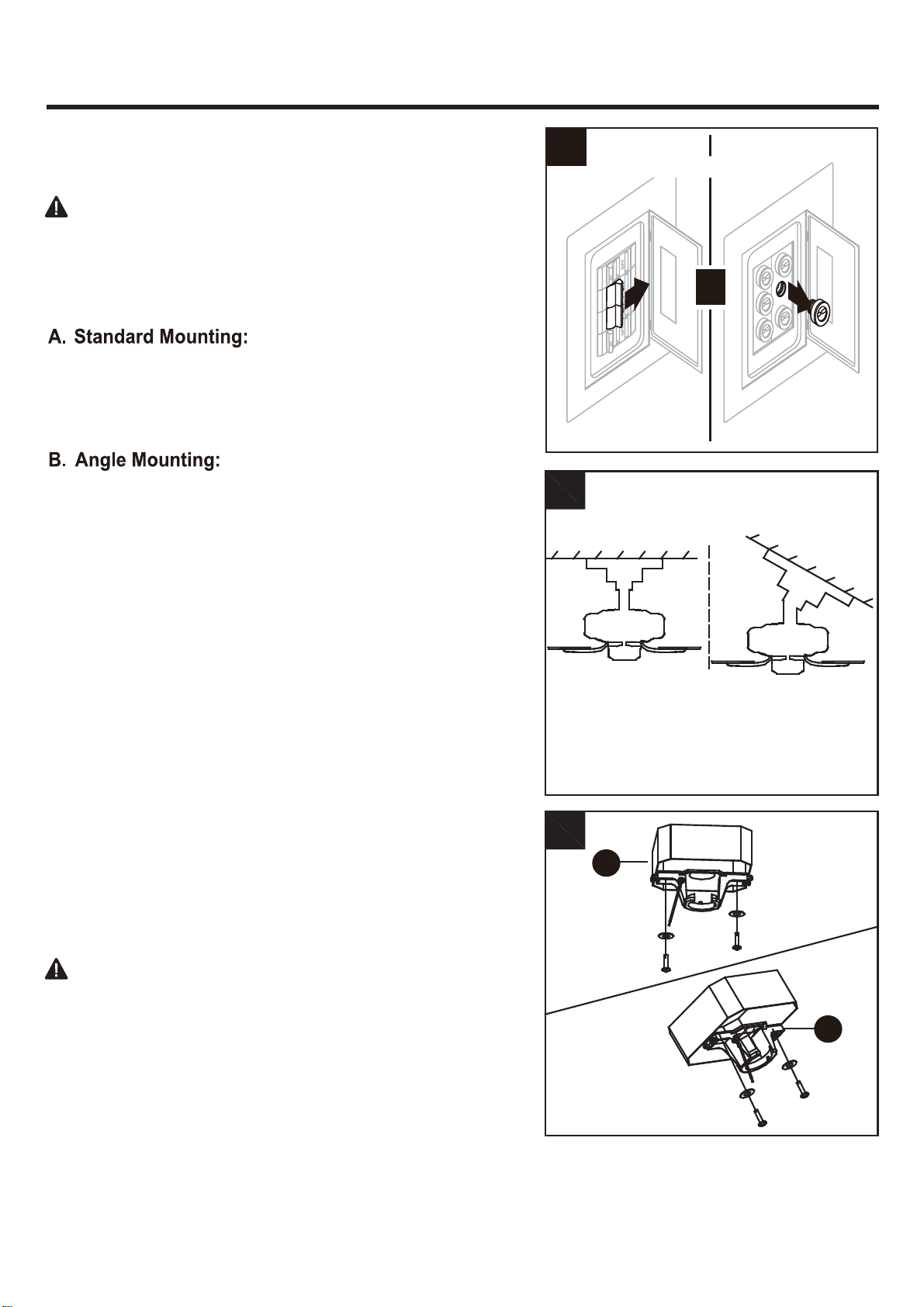
INITIAL INSTALLATION INSTRUCTIONS
DANGER:
Failure to disconnect power supply prior to
1.
Turn off circuit breakers and wall switch to the fan supply
line leads.
2. Choose the desired mounting method:
Standard mounting is best suited for ceilings 8 feet. or
higher. For taller ceilings you may want to use a longer
downrod (not included).
Angle-style mounting is best suited for angled or vaulted
ceilings. A longer downrod is sometimes necessary to
ensure proper blade clearance. If using the angle mount,
make sure the ceiling angle is not steeper than 20°.
3.
Check existing outlet box (not included) to ensure it is
securely fastened to at least two points in a structural
ceiling member and can support the full weight of the fan.
Once verified, install mounting bracket (A) to the outlet
box using the screws and washers provided with the
outlet box.
installation may result in serious injury or death.
DANGER:
A loose outlet box can cause the fan to
Note:
If using the angle mount, make sure open end of
wobble and increase the fan’s potential to fall, which
mounting bracket (A) points toward the ceiling.
could result in serious injury or death.
For ALL mounting options, there must be at least 30 inches
from the blade tip to nearest wall. Also, ensure there is 7
feet from the bottom edge of the blade to the floor.
A
B
2
3
Standard
Mounting
A
Angle
Mounting
A
or
T
Turn Off Power Source
1
7
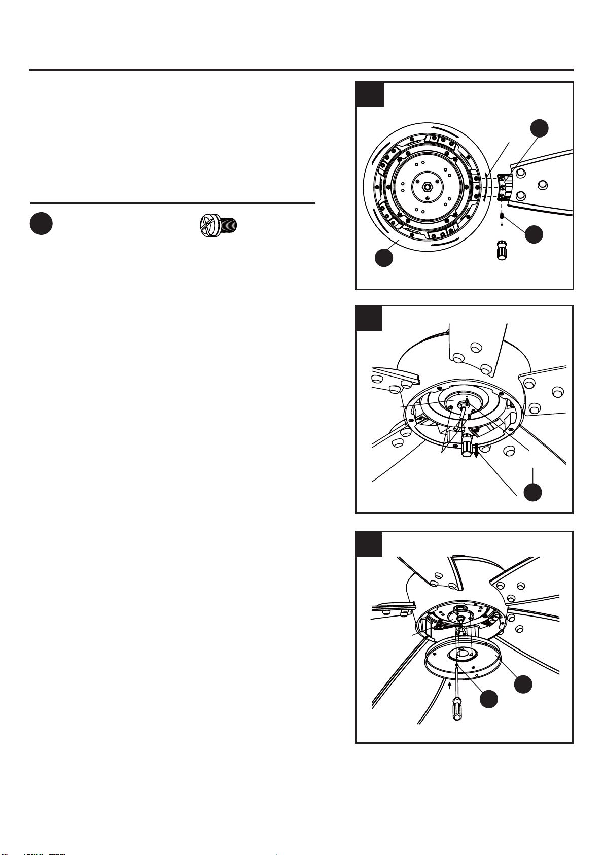
INITIAL INSTALLATION INSTRUCTIONS
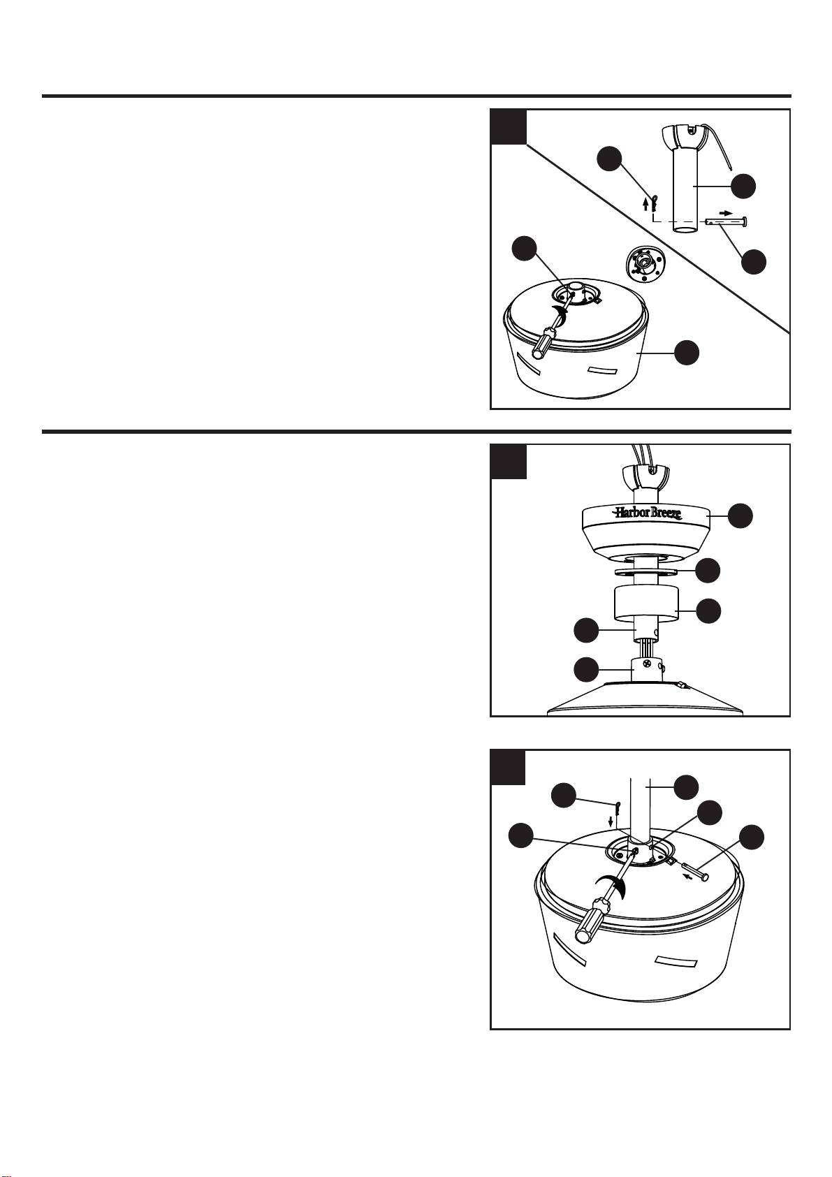
4. Loosen the two coupling screws(P) preassembled in
coupling (Q), but do not remove them.
Remove the hairpin clip (O) and clevis pin (N) from the
downrod assembly (B). Retain for later use.
Note: Make sure to keep loose hardware separate to
avoid confusion during installation.
STANDARD/ANGLE-MOUNTING INSTRUCTIONS
1. Place downrod assembly (B) through canopy (C),
canopy cover (D) and coupling cover (E).
C
D
E
B
Q
1
Feed power wires from motor housing (F) through
downrod assembly (B), then insert downrod assembly
(B) into the coupling (Q) on motor housing (F).
2.
Align the hole on downrod assembly (B) to hole on
coupling (Q), then re-install clevis pin (N). Re-attach
hairpin clip (O) into clevis pin (N) until it snaps into
place, then tighten the two previously loosened
coupling screws (P).
O
P
B
Q
N
2
F
P
B
N
O
4
8
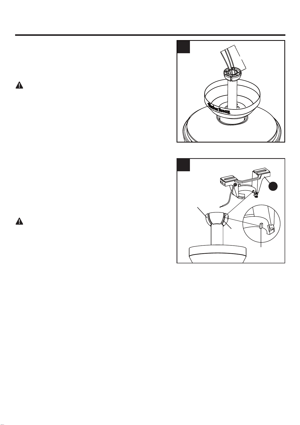
CAUTION: Ensure all screws are tight before moving
onto the next step.
STANDARD/ANGLE-MOUNTING INSTRUCTIONS
3. Cut off excess fixture wires, leaving approximately 6 to
9 inches above the top of the downrod assembly (B).
Strip 1/2 inch of insulation from the end of each fixture
wire.
4. Carefully lift the assembly and rest the hanger ball of
downrod assembly (B) on the mounting bracket (A)
attached to the outlet box. Be sure the groove in the
hanger ball is lined up with the tab on the mounting
bracket (A). This will allow for hands-free wiring.
Proceed to
WIRING on page 9.
DANGER: Be careful when aligning the tab to the
groove ! If not fully engaged, there is a possibility of the
fan falling, which may result in serious injury or death.
3
A
4
Hanger Ball
groove
Tab
6 to 9 in.
9
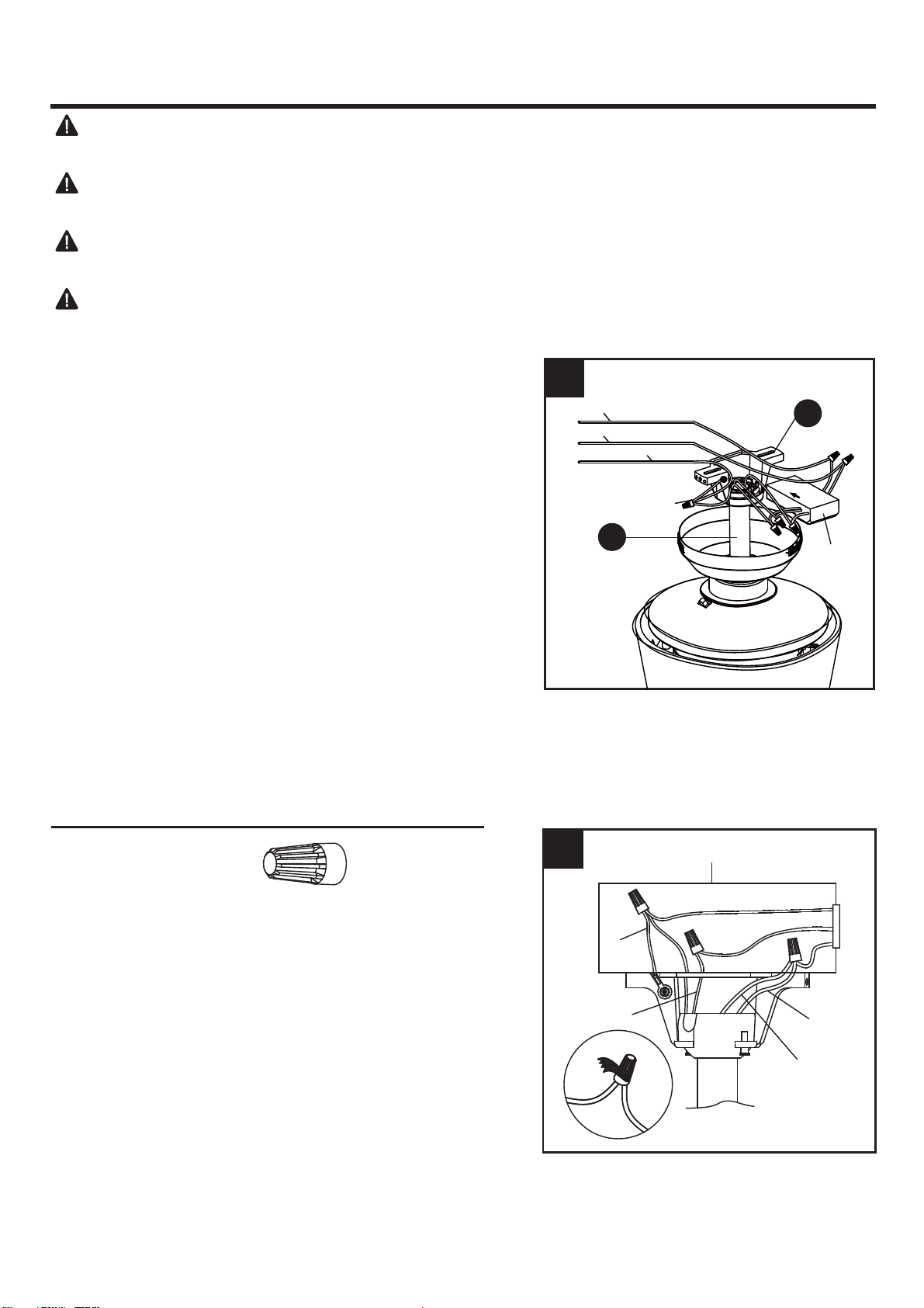
Hardware Used
Wire Connector x 6
WIRING INSTRUCTIONS
1. Follow steps below to wiring your fan, once wiring step
has been completed, slide the wired receiver in between
the mounting bracket (A) and the top of the downrod ball
(B) with the flat side of the receiver facing the ceiling.
Ɣ&RQQHFW:+,7(ZLUHIURPWKHIDQWR:+,7(ZLUHPDUNHG
TO MOTOR N from the receiver.
Ɣ&RQQHFW%/8(ZLUHIURPWKHIDQWR%/8(ZLUHPDUNHG
FOR LIGHT from the receiver.
Ɣ&RQQHFW%/$&.ZLUHIURPWKHIDQWR%/$&.ZLUHPDUNHG
TO MOTOR L from the receiver.
Ɣ&RQQHFW%/$&.ZLUHIURPWKHRXWOHWER[WR%/$&.ZLUH
marked AC IN L from the receiver.
Ɣ&RQQHFW:+,7(ZLUHIURPWKHRXWOHWER[WR:+,7(ZLUH
marked AC IN N from the receiver.
Ɣ&RQQHFW*5281'*5((1ZLUHVIURPPRXQWLQJ
bracket and downrod ball, to GROUND (GREEN or
BARE COPPER) from house.
WARNING: To avoid possible electrical shock, be sure electricity is turned off at the main fuse
box before hanging.
WARNING: If you are not sure if the outlet box is grounded, contact a licensed electrician for
advice, as it must be grounded for safe operation.
WARNING: If house wires are different colors than referred to in the following steps, stop
immediately. A professional electrician is recommended to determine proper wiring.
WARNING: If you feel that you do not have enough electrical wiring knowledge or experience,
have your fan installed by a licensed electrician.
1
2.
2
BLACK
BLUE
WHITE
GREEN
Outlet Box
B
A
Wrap electrical tape (not included) around each wire
connector and make sure no bare wire or wire strands
are visible after making connections. Then, turn wires
upward and carefully push them into the outlet box;
make sure the WHITE and GREEN connections are on
one side and the BLACK connections are on the other
side.
Grounded/Green
Black
Grounded/Green
White
Receiver
10
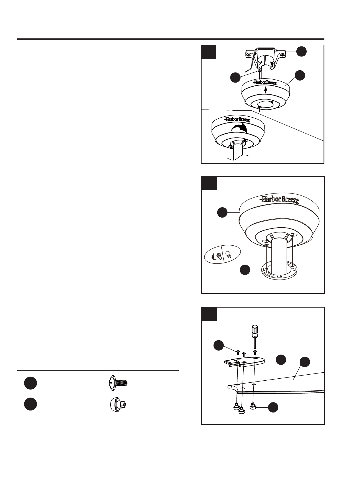
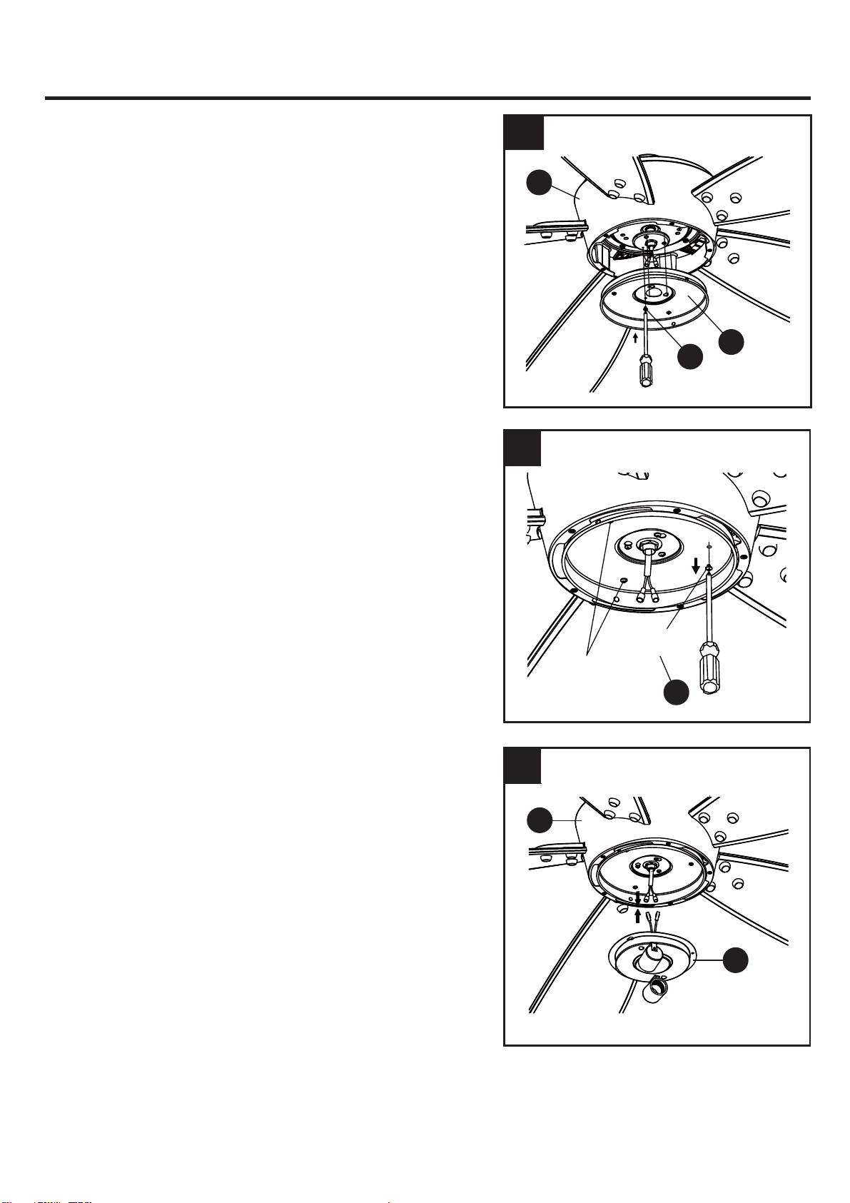
FINAL INSTALLATION INSTRUCTIONS
1. Loosen (but do not remove) the two preassembled
mounting screws (R) on mounting bracket (A) that align
with the slotted holes on canopy (C). Lift canopy (C) up
so slotted holes engage loosened screw heads on
mounting bracket (A), then twist canopy (C) clockwise,
then tighten all screws securely.
2. Raise canopy cover (D) over the mounting screws visible
in canopy (C). Rotate canopy cover (D) clockwise until it
locks into place. You may need to adjust the mounting
screws until the canopy (C) and canopy cover (D) have
a snug fit.
3. Attach blade (H) under blade arm (G) using three (3)
decorative nuts (CC) and three (3) blade screws (AA).
Repeat for remaining blades (H), blade arms (G),
decorative nuts (CC) and three (3) blade screws (AA).
2
Hardware Used
Blade Screw x 15
x 15
AA
Decorative Nut
CC
1
R
A
C
D
C
3
G
H
AA
CC
11
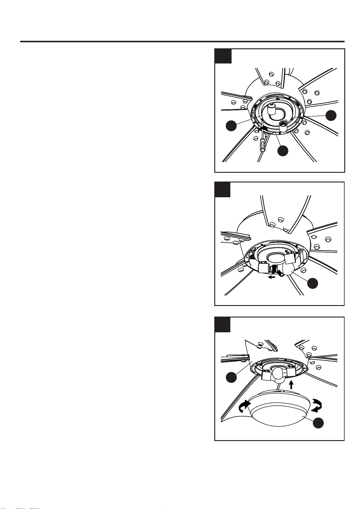
FINAL INSTALLATION INSTRUCTIONS
6. Insert the wires from the motor housing (F) through the
center hole in the switch housing (I). Attach the switch
housing (I) to the mounting plate on motor housing (F)
by placing the keyslot holes from the switch housing (I)
onto the two protruding mounting screw (S) heads.
4. Insert blade assembly through slot on fan motor
assembly (F) and align three screw holes in blade arm
(G) with screw holes in fan motor assembly (F). Secure
with three blade arm screws (BB). Repeat for remaining
blade assemblies.
4
5. Remove one of the mounting screws (S) on mounting
plate of motor housing (F), then loosen the other two.
Blade Arm Screw
x 15
BB
Hardware Used
5
6
BB
G
S
I
F
Mounting
Plate
Slot
Mounting
Plate
S
Screw
(remove)
Screws
(loosen only)
T
J
F
S
I
F
12
FINAL INSTALLATION INSTRUCTIONS
9. Connect the 2 single pin connectors from the light kit
(J) to the 2 single pin connectors from motor
assembly(F). Connect the black wire to black wire, and
white wire to white wire.
7. Adjust the switch housing (I) until the screw heads are
aligned with the keyholes, then re-insert mounting
screw (S) previously removed on step 5. Tighten all
mounting screws (S) securely.
7
8. Remove one of the screws (T) on switch housing (I),
then loosen the other two.
8
9
Screws
(loosen only)
Screw
(remove)
G
J
T
L
K
F
13
FINAL INSTALLATION INSTRUCTIONS
10. Adjust the light kit (J ) until the screw heads are
aligned with the keyholes, then re-insert mounting
screw (T) previously removed on step 8. Tighten all
mounting screws (T) securely.
10
11. Install light bulbs (L) into sockets.
11
12. Secure the glass (K) to switch housing (I) by twisting
in a clockwise direction. Do not over-tighten.
12
14
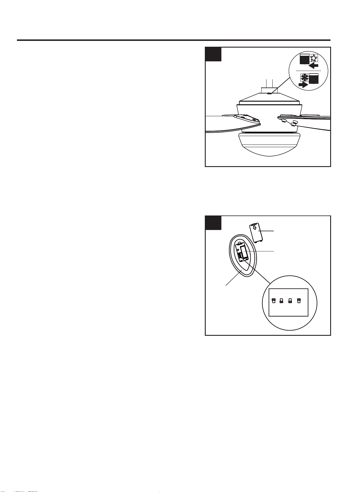
OPERATING INSTRUCTIONS
1. When the season changes, you may want to change
the direction in which the fan spins.
In warmer weather, counterclockwise rotation creates a
downward airflow, which cools the air. Push the switch
LEFT and see a SUN icon.
In cooler weather, clockwise rotation creates an upward
airflow,which moves hot air from the ceiling. Push the
switch
RIGHT and see a SNOWFLAKE icon.
WARNING: Turn off and wait for fan to stop before
flipping the reverse switch.
Note:Use a small screwdriver or ballpoint pen to move
the reverse switch if you have difficulty doing so by
hand.
1
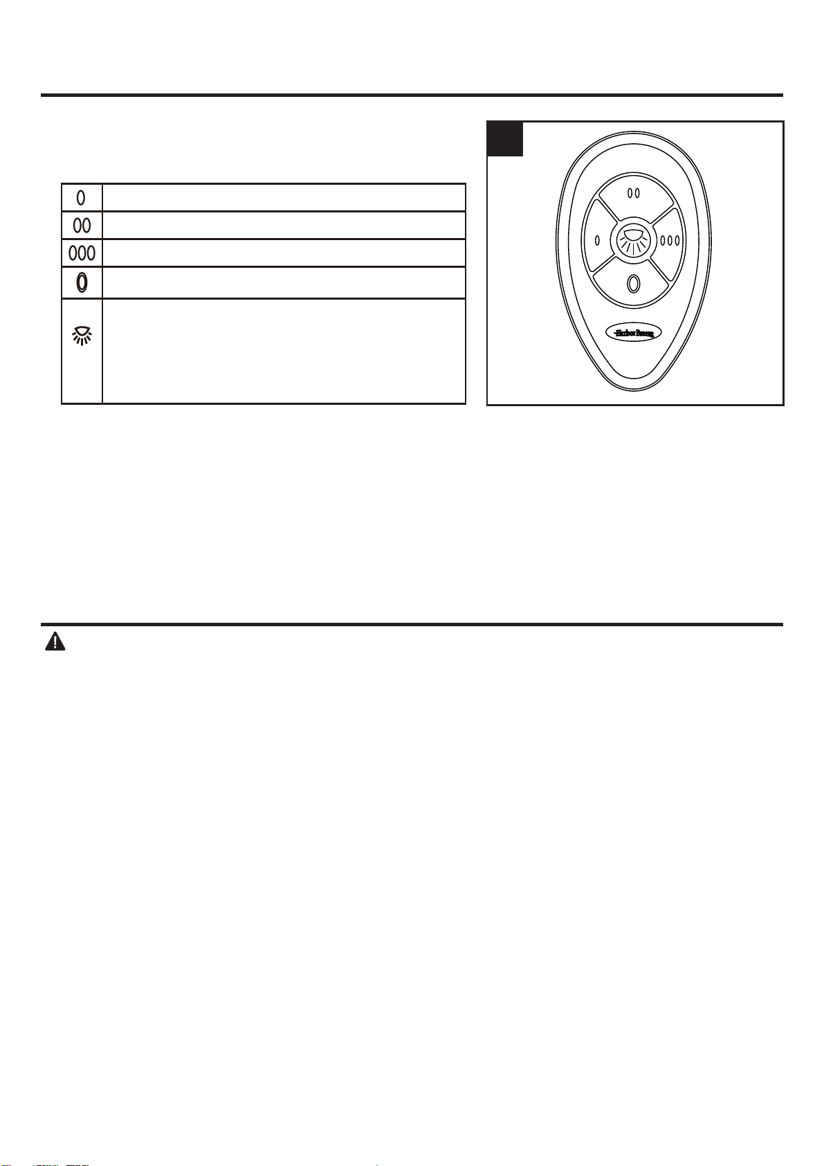
2. The remote unit has 16 different code combinations. To
prevent possible interference from the other remote
units, simply change the combination code in the
remote by following the set up procedures listed below.
a.)Remove the remote control battery cover to expose
the remote dip switches. Use a small ballpoint pen (not
included) to set the dip switches to either up or down.
NOTE:
Factory setting is all up. Do not use this
position.
b.)Install the 23A 12V battery (included) and replace
the battery cover you previously removed.
c.)Restore power to the fan, press and hold the “Light”
button until the light flashes (on/off) 3 times and will
stay on, then the control and speed setting process is
complete.
NOTE:
You must press the “Light” button within 30
seconds of restoring power to the fan.
d.)If programming is unsuccessful, retry the above
instructions.
NOTE:
Remove batteries if remote has not been used
for a long period of time in order to avoid damage.
Store remote away from excessive heat or humidity.
2
Remote
Battery Door
Battery
2
1
3
4
ON
DIP
CARE AND MAINTENANCE
Important: Shut off main power supply before beginning any maintenance. Do not use water or a
damp cloth to clean the ceiling fan.
. At least twice each year, tighten all screws and lower canopy to check mounting plate screws.
. Clean fan housing with only a soft brush or lint-free cloth to avoid scratching the finish. Clean blades
with a lint-free cloth. You may occasionally apply a light coat of furniture polish to wood blades for
. Bulb replacement: Use two 5.5 W max. type A-15 LED bulbs. CFL bulbs are not recommended for
this item.
added protection.
15
OPERATING INSTRUCTIONS
3. The buttons on the remote control the fan speed and
light as follows:
Note: This receiver has a preset memory function;
when the switch is turned OFF, the control will
remember the light intensity and fan speed. When the
switch is turned ON, the light and fan will resume
operation as they were prior to the switch being turned
OFF.
Low speed
Medium speed
High speed
Turn the fan off
Press the light key quickly and turn the light ON
or OFF.
Press and hold to dim light.
The light will cycle from bright to dim to bright
until button is released.
3
1. Set screws are loose. 1. Tighten all set screws.
2. Usi
ng non-approved speed control.
2. S
ome fan motors are sensitive to signals from solid-
state varible speed controls. DO NOT USE a solid-
state variable speed control.
3. Norm
al noise. 3
. A
llow "break-in" period of 24 hours. Most noises
associated with a new fan will disappear after this
period.
4. W
ire connectors inside switch
housing rattling.
4. Check
to m
ake sure wire connectors in switch
housing are not rattling against each other or against
the interior wall of the switch housing.
5. Cracked bl
ade. 5
. Repl
ace blades.
6. The distance from canopy to ceiling
is too great.
6. Make sure upper canopy is a short distance from
ceiling. It should not touch the ceiling.
7. Glass is not secure. 7
. Secure the gl
ass.
1. Hanger bracket and/or ce
i
ling outlet
box is not securely fastened.
1. T
ighten the hanger bracket screws to the outlet box,
and/or secure outlet box.
2. Set screw
in downrod assembly is
loose.
2. T
ighten the set screw in the downrod assembly.
seated in canopy tabs.
3. F
an hanger ball is not properly 3
. T
urn power off, support the fan very carefully, and
check that the hanger ball is properly seated.
4. S
et screw in motor coupling is loose.
4. Rai
se motor coupling up and tighten set screws
securely.
5. B
lade is lo
ose. 5. Check that al
l blades are screwed firmly into blade
holders.
Fan sounds noisy
Fan wobbles
TROUBLESHOOTING
PROBABLE CAUSE CORRECTIVE ACTION
PROBLEM
16
6. Blade holders are loose. 6. Check to be sure the fan blade irons seat firmly and
uniformly on the surface of the motor. If flanges are
seated incorrectly, loosen the flange screws and
retighten.
7. B
lade out of balance. 7
. Interchange tw
o adjacent blades; this will redistribute
the weight and possibly result in smoother operation.
8. F
an too close to vaulted ceili
ng
8. Low
er or move fan. Extension downrods may be
ordered.
9. T
ransition to different speed.
9. W
hen switching from medium to low speed, you may
notice some fan wobble in the fan. When the fan
stabilizes at low speed, wobble should disappear.
10. F
an not securely mounted.
10. M
ake sure canopy and mounting bracket are
tightened securely to ceiling joist.
1. Power turned off, fuse blown or
circuit
breaker tripped.
1. T
urn power on, replace fuse or reset breaker.
3. M
otor reversing switch not engaged.
3. P
ush switch firmly right or left. Fan will not operate
when switch is in the middle.
1. W
rong wire connection.
1. Refer to S
tep 3, page 12 to ensure all wire
2. Bulb is burned out. 2. Replace the bulbs.
connections were done correctly.
Fan d
oes not start
2b. Check the plug connection in the switch housing.
2a. Turn power off and loosen canopy; check all
connections according to section WIRING
INSTRUCTIONS on page 9.
2. Loose w
ire connections or wrong
connections.
Light does not work

17
LIMITED LIFETIME WARRANTY
The manufacturer warrants this fan to be free from defects in workmanship and material present at
time of shipment from the factory for life (with limitations) from the date of purchase. This warranty
applies only to the original purchaser. The manufacturer agrees to correct such defect at no char
ge
or, at our option, replace the ceiling fan with a comparable or superior model.
To obtain warranty service, present a copy of your sales receipt as proof of purchase. All cost of
removal and reinstallation are the expressed responsibility of the purchaser. Any damage to the
ceiling fan by accident, misuse or improper installation, or by affixing accessories not produced by
this warranty, are at the purchaser’s own responsibility. The manufacturer assumes no responsibility
whatsoever for fan installation during the limited lifetime warranty. Any service performed by an
unauthorized person will render the warranty invalid.
Due to varying climatic conditions, this warranty does not cover changes in brass finish, rusting,
pitting, tarnishing, corroding or peeling. Brass finish fans maintain their beauty when protected from
varying weather conditions.
Any replacement of defective parts for the ceiling fan must be reported within the first year from
the date of purchase. For the balance of the warranty, call our customer service department at
888-251-1003 for return authorization and shipping instructions so that we may repair or replace the
ceiling fan. Any fan or parts returned improperly packaged is the sole responsibility of the purchaser.
There is no further expressed warranty. The manufacturer disclaims any and all implied warranties.
The duration of any implied warranty which can not be disclaimed is limited to the lifetime limited
period as specified in our warranty. The manufacturer shall not be liable for incidental, consequential
or special damages arising at or in connection with product use or performance except as may other
wise be accorded by law. This warranty gives you specific legal rights, and you also have other rights
which vary from state to state. This warranty supersedes all prior warranties.
NOTE: A small amount of “ wobble ” is normal and should not be considered a defect.
FCC WARNING
This device complies with Part 15 of the FCC Rules. Operation is subject to the following two
conditions:
(1) This device may not cause harmful interference, and (2) this device must accept any interference
received, including interference that may cause undesired operation. Please note that changes or
modifications not expressly approved by the party responsible for compliance could void the user's
authority to operate the equipment.
Note: This equipment has been tested and found to comply with the limits for Class B digital device,
pursuant to part 15 of the FCC Rules. These limits are designed to provide reasonable protection
against harmful interference in a residential installation.
This equipment generates, uses and can radiate radio frequency energy and, if not installed and
used in accordance with the instructions, may cause harmful interference to radio or television
reception, which can be determined by turning the equipment off and on, the user is encouraged to
try to correct the interference by one or more of the following measures:
- Reorient or relocate the receiving antenna.
- Increase the separation between the equipment and the receiver.
- Connect the equipment into an outlet on a circuit different from that to which the receiver is
connected.
Consult the dealer or an experienced radio/TV technician for help.
18
Printed in China
REPLACEMENT PART LIST
For replacement parts, call our customer service department at 888-251-1003, 8 a.m. - 8 p.m., EST,
Monday
- Sunday. You could also contact us at [email protected] or visit www.lowespartsplus.com.
A Mounting Bracket
B Downrod Assembly
C Canopy
D Canopy Cover
E Coupling Cover
G Blade Arm
H Blade
I Switch Housing
J Light Kit
K Glass Bowl
Blade Screw
Decorative Nut
Blade Arm Screw
AA
BB
CC
Part Description Part#
A
D
K
AA
BB
CC
E
I
J
H
B
C G
A102-0219018
A103-0279301
A101-0499301
A108-0013301
A106-0171301
A143-0383301
A141-0619001
A121-0454301
A187-0485030
A187-0491030
B168-0599301