Loading ...
Loading ...
Loading ...
Thetoolcanalsobeoperatedbyholdingtriggerdepressed
andpushingcontacttripagainstworkpiece.Thisoperating
procedureprovidesrapid-firefastenerdriving.Neveroper-
atetoolunlesscontacttripisincontactwithworkpiece.
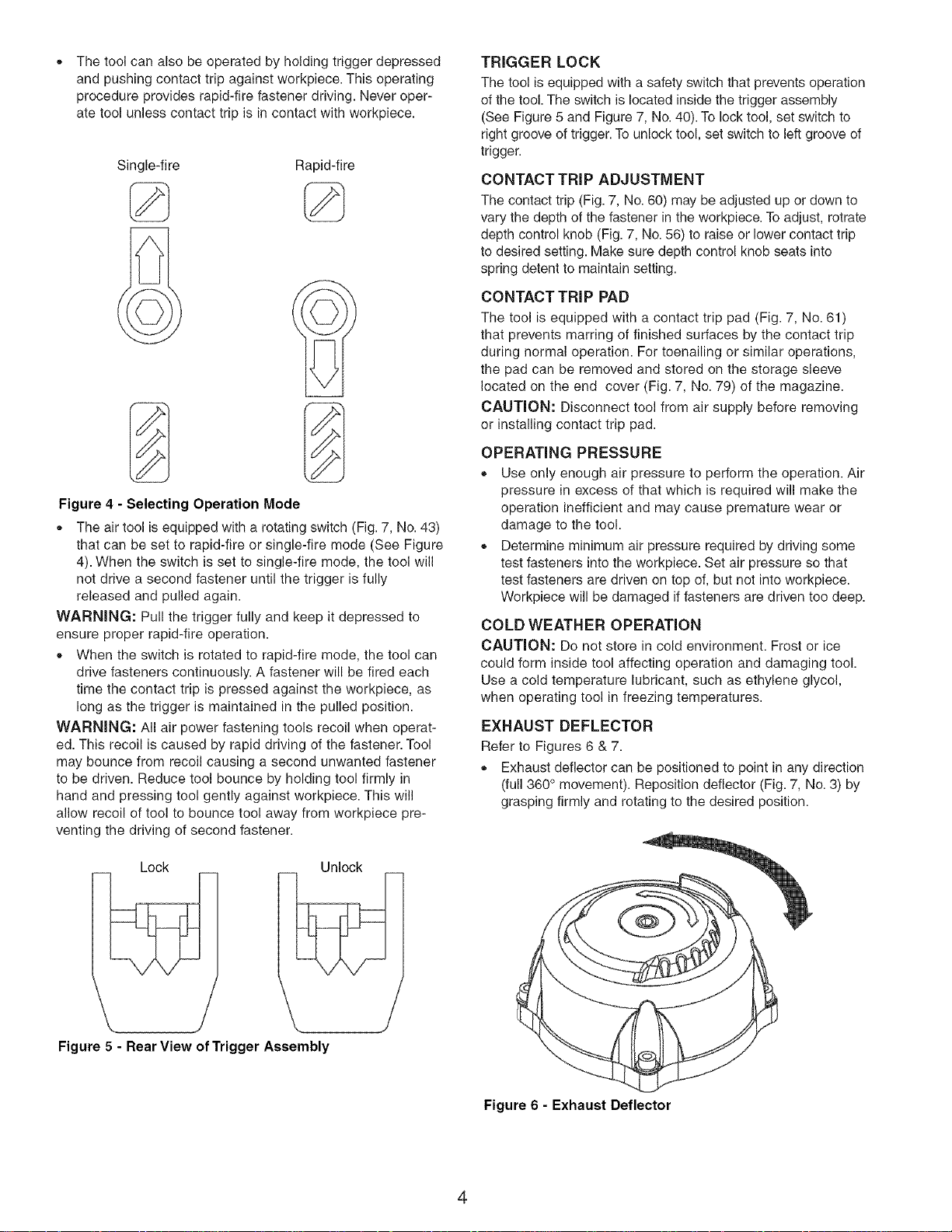
Single-fire Rapid-fire
Figure 4 - Selecting Operation Mode
,, The air tool is equipped with a rotating switch (Fig. 7, No. 43)
that can be set to rapid-fire or single-fire mode (See Figure
4). When the switch is set to single-fire mode, the tool will
not drive a second fastener until the trigger is fully
released and pulled again.
WARNING: Pull the trigger fully and keep it depressed to
ensure proper rapid-fire operation.
,, When the switch is rotated to rapid-fire mode, the tool can
drive fasteners continuously. A fastener will be fired each
time the contact trip is pressed against the workpiece, as
long as the trigger is maintained in the pulled position.
WARNING: All air power fastening tools recoil when operat-
ed. This recoil is caused by rapid driving of the fastener. Tool
may bounce from recoil causing a second unwanted fastener
to be driven. Reduce tool bounce by holding tool firmly in
hand and pressing tool gently against workpiece. This will
allow recoil of tool to bounce tool away from workpiece pre-
venting the driving of second fastener.
Lock Unlock
Figure 5 - Rear View of Trigger Assembly
/
TRIGGER LOCK
The tool is equipped with a safety switch that prevents operation
of the tool. The switch is located inside the trigger assembly
(See Figure 5 and Figure 7, No. 40). To lock tool, set switch to
right groove of trigger. To unlock tool, set switch to left groove of
trigger.
CONTACT TRIP ADJUSTMENT
The contact trip (Fig. 7, No. 60) may be adjusted up or down to
vary the depth of the fastener in the workpiece. To adjust, rotrate
depth control knob (Fig. 7, No. 56) to raise or lower contact trip
to desired setting. Make sure depth control knob seats into
spring detent to maintain setting.
CONTACT TRIP PAD
The tool is equipped with a contact trip pad (Fig. 7, No. 61)
that prevents marring of finished surfaces by the contact trip
during normal operation. For toenailing or similar operations,
the pad can be removed and stored on the storage sleeve
located on the end cover (Fig. 7, No. 79) of the magazine.
CAUTION: Disconnect tool from air supply before removing
or installing contact trip pad.
OPERATING PRESSURE
,, Use only enough air pressure to perform the operation. Air
pressure in excess of that which is required will make the
operation inefficient and may cause premature wear or
damage to the tool.
,, Determine minimum air pressure required by driving some
test fasteners into the workpiece. Set air pressure so that
test fasteners are driven on top of, but not into workpiece.
Workpiece will be damaged if fasteners are driven too deep.
COLD WEATHER OPERATION
CAUTION: Do not store in cold environment. Frost or ice
could form inside tool affecting operation and damaging tool.
Use a cold temperature lubricant, such as ethylene glycol,
when operating tool in freezing temperatures.
EXHAUST DEFLECTOR
Refer to Figures 6 & 7.
,, Exhaust deflector can be positioned to point in any direction
(full 360 ° movement). Reposition deflector (Fig. 7, No. 3) by
grasping firmly and rotating to the desired position.
Figure 6 - Exhaust Deflector
4
Loading ...
Loading ...
Loading ...