
Loading ...
Loading ...
Loading ...
8
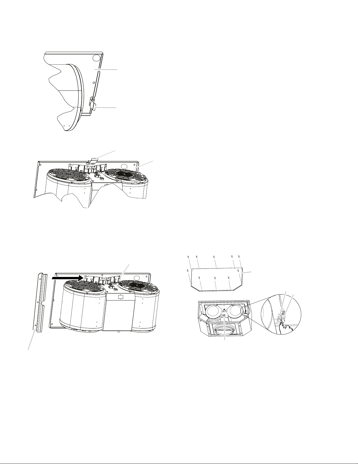
3 Remove the motor mounting plate by setting free the
spring clip. NOTE: The spring clip should be outside the
slot in the mounting plate.
A. Mounting plate
B. Spring Clip
A
B
A. Mounting plate
B. Spring Clip
A
B
4 Run out the power supply wires and connector through
the hole in the right end of the motor mounting plate.
5 Slide out the left mounting plate from under the motor
mounting bracket.
A
B
A. Motor mounting plate
B. Motor mounting bracket
6 Install the grease filters.
Prepare for Mounting the In-Line Blower System
The In-Line Blower System must be fastened to a secure
structure of the roof, ceiling, wall, floor, or new or existing
frame construction. The 4 holes on either the inlet (bottom)
side or the outlet (top) side of the blower must be used to
mount the in-line blower system to the structure.
NOTE: The mounting hole locations must span the studs.
Additional stud framing may be required. Plywood may be
used to span open areas between ceiling joists or roof rafters
to aid installation. This structure must be strong enough to
support the weight of the in-line blower system (50 lb [22.6
kg] min).
Prepare the In-line Blower System
I WARNING
Excessive Weight Hazard
Use two or more people to move and install range hood.
Failure to do so can result in back or other injury.
1 Disconnect power.
2 Determine which venting method to use: roof or wall
exhaust.
3 Using two or more people, move the in-line blower motor
system to the mounting location.
4 Remove the 10 screws from the front cover of the in-line
blower motor housing and set them aside.
5 Remove the front cover of the in-line blower motor
housing and set it aside.
NOTE: To make the in-line blower motor housing easier to
mount, the blower motor assembly can be removed.
6 Disconnect the motor electrical plug from the blower
motor assembly.
7 Remove the screws that secure the blower motor
assembly to the in-line blower housing and set them aside.
8 Pull the spring clip to release the blower motor assembly.
Remove the blower motor assembly from the housing and
place it on a covered surface.
A
B
C
D
A. Front cover
B. Blower mounting
screws
C. Spring clip
D. Motor electrical
plug
Loading ...
Loading ...
Loading ...