
Loading ...
Loading ...
Loading ...
10
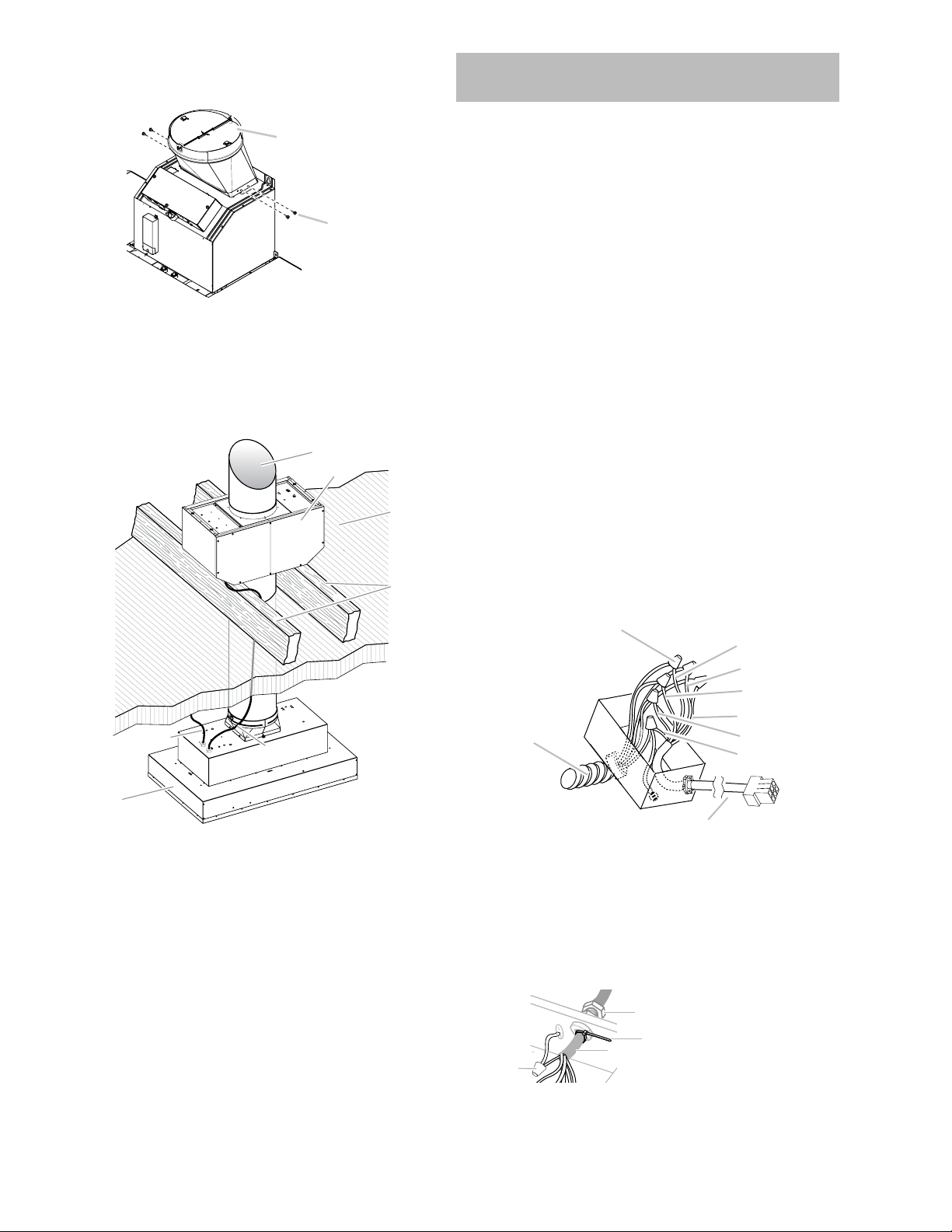
7 If necessary remove the range hood transition.
A
B
A. Transition
B. Transition screws
8 Install the conduit connectors and conduit to the in-line
blower housing and range hood electrical terminal boxes.
NOTE: If removed, install the range hood transition.
9 Connect the vent system to the range hood and in-line
blower system and seal all joints with clamps.
F
E
B
G
A
C
D
A. Vent System
B. In line Blower Motor
C. Ceiling
D. Roof rafters/ Plywood
E. In line Blower Wiring
Conduit (not included)
F. Power Supply Wiring
Conduit
G. Hood Insert
Make Electrical Connection for In-Line Blower
Motor System
I WARNING
Electrical Shock Hazard
Disconnect power before servicing.
Replace all parts and panels before operating.
Failure to do so can result in death or electrical shock.
I WARNING
Electrical Shock Hazard
Electrically ground blower.
Connect ground wire to green and yellow ground wire in
terminal box.
Failure to do so can result in death or electrical shock.
NOTE: The electrical diagram is attached at the end of the
document.
Electrical Connection Inside In-line Blower System
1 Disconnect power.
2 Connect the wires from the wiring conduit to the wires
from the motor electrical plug cable inside the in-line
blower housing terminal box.
3 Use UL listed wire connectors and connect the black wires
(C) together.
4 Use UL listed wire connectors and connect the white wires
(D) together.
5 Use UL listed wire connectors and connect the red wires
(E) together.
6 Use UL listed wire connectors and connect the blue wires
(F) together.
7 Use UL listed wire connectors and connect the gray wires
(G) together.
8 Connect the green (or green/yellow) ground wire from the
wiring conduit to the green (or yellow/green), ground wire
(H) in the terminal box using UL listed wire connectors.
A
B
C
D
E
F
G
H
I
A. Strain relief
B. UL listed wire
connectors
C. Black wires
D. White wires
E. Red wires
F. Blue wires
G. Gray wires
H. Green (or yellow/
green) and green /
yellow wires
I. Motor electrical plug
cable
9 Once the connection is done, is necessary to adjust the
9-6 wire connector with the included strap.
A. Ground wires
connection
B. 6-9 wire connector
C. Strap
D. Strain relief
A
B
C
D
10 Reinstall the in-line blower terminal box cover and screws.
11 Reinstall the front cover of the in-line blower housing and
secure it with 10 mounting screws.
Loading ...
Loading ...
Loading ...