MODEL NUMBER 917.258872
OWNER'S MANUAL
Assembly
° Operation
o Customer ResponsibiHtBes
° Service and Adjustments
Repair Parts
For answers to your questions
about this product, Call:
1-800-659-5917
Sears Craftsman Help Line
5 am - 5 pm, Mon - Sat
CAUTION: Read and follow all safety rules and instructions before operating this equipment.
FOR CONSUMER ASSISTANCE HOT LINE, CALL THIS TOLL FREE NUMBER: 1-800-659-5917
I. GENERAL OPERATION
• Read, understand, and follow all instructions in the manual
and on the machine before starting.
• Onty allow responsible adults, who are familiar with the
instructions, to operate the machine.
• Clear the area of objects such as rocks, toys, wire, etc.,
which could be picked up and thrown by the blade.
= Be sure the area is clear of other people before mowing. Stop
machine if anyone enters the area_
• Never carry passengers.
° Do not mow in reverse unless absolutely necessary_ Always
look down and behind before and while backing.
• Be aware of the mower discharge direction and do not point
it at anyone Do not operate the mower without either the
entire grass catcher or the guard in placer
° Slow down before turning,
• Never leave a running machine unattended. Always turn off
blades, set parking brake, stop engine, and remove keys
before dismounting.
• Turn off blades when not mowing.
= Stop engine before removing grass catcher or unclogging
chute.
. Mow only in daylight or good artificial light
• Do not operate the machine while under the influence of
alcohol or drugs
. Watch for traffic when operating near or crossing roadways.
• Use extra care when loading or unloading the machine into
a trailer or truck.
SAFETY RULES
Safe Operation Practices for Ride-On Mowers
IMPORTANT: THIS CUTTING MACHINE IS CAPABLE OF AMPUTATING HANDS AND FEET AND THROWING OBJECTS_
FAILURE TO OBSERVE THE FOLLOWING SAFETY INSTRUCTIONS COULD RESULT IN SERIOUS INJURY OR DEATH.
III. CHILDREN
IL SLOPE OPERATION
Slopes are a major factor related to loss-of-control and
tipover accidents, which can result in severe injury or deatho
All slopes require extra caution. If you cannot back up the
slope or if you feel uneasy on it, do not mow it.
DO:
o Mow up and down slopes, not across.
. Remove obstacles such as rocks, tree limbs, etc.
• Watch for holes, ruts, or bumps. Uneven terrain could
overturn the machine. Tal! grass can hide obstacles.
o Use stow speed Choose a low gear so that you will not have
to stop or shift while on the slope_
o Follow the manufacturer's recommendations for wheel
weights or counterweights to improve stability_
= Use extra care with grass catchers or other attachments_
These can change the stability of the machine.
° Keep all movement on the slopes slowand gradual Do not
make sudden changes in speed or direction.
= Avoid starting or stopping on a slope, if tires lose traction,
disengage the blades and proceed slowly straight down the
slope.
2
DO NOT:
. Do not turnon slopes unless necessary, and then, turn slowly
and gradually downhill, if possible..
• Do not mow near drop-offs, ditches, or embankments, The
mower could suddenly turn over if a wheel is over the edge
of a cliff or ditch, or ifan edge caves in.
= Do not mow on wet grass., Reduced traction could cause
sliding
• Do not try to stabilize the machine by putting your foot on the
ground_
= Do not use grass catcher on steep slopes.
Tragic accidents can occur if the operator is not alert to the
presence of children_ Childr.en are often attracted to the
machine and the mowing activity., Never assume that
children will remain where you last saw them°
. Keep children out of the mowing area and under the watchful
care of another responsible adulL
• Be alert and turn machine off if children enter the area
• Before and when backing, look behind and down for small
children.
o Never carry children. They may fall off and be seriously
injured or interfere with safe machine operation_
• Never allow children to operate the machine..
• Use extra care when approaching blind corners, shrubs,
trees, or other objects that may obscure vision_
o
o
I
!
IV. SERVICE
• Use extra care in handling gasoline and other fuels. They are
flammable and vapors are explosive.
Use only an approved container.
Never remove gas cap or add fuel with the engine
running. Allow engine to cool before refueling. Do not
smoke,
Never refuel the machine indoors.
Never store the machine or fuel container inside where
there is an open flame, such as a water heater.
• Never run a machine inside a closed area..
= Keep nuts and bolts, especially bIade attachment bolts, tight
and keep equipment in good condition.
° Never' tamper with safety devices. Check their proper
operation regularly_
° Keep machine free of grass, leaves, or other debris build-up.
Clean oil or fuel spillage. Allow machine to coo] before
storing_
° Stop and inspect the equipment if you strike an object.
Repair, if necessary, before restarting..
. Never make adjustments or repairs with the engine running.
° Grass catcher components are subject to wear, damage, and
deterioration, which could expose moving parts or altow
objects to be thrown. Frequently check components and
replace with manufacturer s recommended parts, when nec-
essary
Mower blades are sharp and can cut Wrap the blade(s) or
wear gloves, and use extra caution when servicing them
Check brake operation frequently. Adjust and service as
required.
...................- .......... " ,1_ i, i, ,
,_ Look for' this symbol to point out im-
,_ A portant safety precautions. It means
CAUTION!!! BECOMEALERT!t! YOUR
SAFETY IS INVOLVED.
.........• ..:......., : ...................... k _ ' I' ' ' I IL
CAUTION: Always disconnect spark plug
,_ wire and place wire where it cannot contact
spark plug in order to prevent accidental
starting when setting up, transporting,
.......... adjusting or making repairs° ................
kl_' I
WARNHNG
The engine exhaust from this product con-
tains ctiemicals known to the State of Califor-
nia to cause cancer, birth defects, or other
reproductive harm.
.......... k"l '_1 n "H'I' ,......

CONGRATULATIONS on your purchase of a Sears
Tractor, It has been designed, engineered and manufac-
tured to give you the best possibte dependability and
performance
Should you experience any problem you cannot:easily
remedy, please contact your nearest Sears Authorized
Service Center/Department Department, We have com-
petent, wett4rained technicians and the proper tools to
service or repair this tractor.
Please read and retain this manual, The instructions will
enable you to assemble and maintain your tractor properly
Always observe the "SAFETY RULES",,
MODEL
NUMBER 9! 7.258872
SERIAL
NUMBER
DATEOFPURCHASE
THEMODELANDSERIALNUMBERSWlLLBEFOUND
ON A PLATE UNDER THE SEAT
YOU SHOULD RECORD BOTH SERIAL NUMBER AND
DATE OF PURCHASE AND KEEP IN A SAFE PLACE
.FOR FUTURE REFERENCE. .......
MAINTENANCE AGREEMENT
A Sears Maintenance Agreement is available on this prod-
uct Contact your nearest Sears store for details.
CUSTOMER RESPONSIIBBUTOES
o Read and observe the safety rules_
o Follow a regular schedule in maintaining, caring for and
using your tractor,.
. Follow the instructions under "Customer Responsibili-
ties" and "Storage" sections of this owner's manual,.
PRODUCT SPEClIFilCATgONS
HORSEPOWER: I8.5
GASOLINE CAPACITY 3 5 GALLONS
AND TYPE: ........ UNLEADED REGULAR
O1L TYPE (API-SF/SG): SAE10W30 (above 32°F)
SAE 5W-30 (below 32°F)
OIL CAPACITY: W/FILTER: 42 PINTS
W/O FILTER: 37 PINTS
SPARK PLUG: CHAMPION RC12YC
(GAP: .030")
VALVE CLEARANCE: NOT ADJUSTABLE
GROUND SPEED (MPH): FORWARD: 0 - 58
REVERSE: 0-21
TIRE PRESSURE: FRONT: 14 PSI
REAR: 10 PSI
CHARGING SYSTEM: 15 AMPS @ 3600 RPM
BA-I-I-ERY: AMPiHR: 30
MIN CCA: 240
CASE SIZE: U1R
BLADE BOLT TORQUE: 30-35 FT LBS.
WARNING: This tractor is equipped with an internal
combustion engine and should not be used on ot"near any
unimproved forest-covered, brush-covered or grass-cov-
ered land unless the engine's exhaust system is equipped
with a spark arrester meeting applicable local or state laws
(if any).. If a spark at'rester is used, it should be maintained
in effective working order by the operator..
In the state of California the above is required by law
(Section 4442 of the California Public Resources Code)..
Other states may have similar laws. Federal laws apply on
federal lands.. A spark arrester for the muffler is available
through your nearest Sears Authorized Service Center/
Department (See REPAIR PARTS section of this manual)..
LRMITED TWO YEAR WARRANTY ON CRAFTSMAN RRDIING EQUIPMENT
For two (2) years from the date of purchase, if this Craftsman Riding Equipment is maintained, lubricated and tuned up according
to the instructions in the owner's manual, Sears will repair or replace, free of charge, any parts found to be defective in material
or workmanship
This Warranty does not cover:
, Expendable items which become worn during normal use, such as blades, spark plugs, air cleaners, belts, etc.
° Tire replacement or repair caused by punctures from outside objects, such as nails, thorns, stumps, or glass..
o Repairs necessary because of operator abuse, negligence, improper storage or accident or the failure to maintain the
equipment according to the instructions contained in the owner's manual
° Riding equipment used for commercial or rental purposes
LIbllTED 90 DAY WARRANTY ON BATTERY
For ninety (90) days from date of purchase, if any battery included with this riding equipment proves defective in material or
workmanship and our testing determines the battery witl not hold a charge, Sears will replace the battery at no charge
IN-HOME WARRANTY SERVICE ON YOUR CRAFTSMAN RIDING EQUIPMENT IS AVAILABLE AT NO-CHARGE FOR 30
DAYS FROM THE DATE OF PURCHASE, PLEASE CONTACT YOUR NEAREST SERVICE CENTER AFTER 30 DAYS
FROM THE DATE OF PURCHASE, WARRANTY SERVICE IS AVAILABLE BY TAKING YOUR CRAFTSMAN RIDING EQUIP-
MENT TO YOUR NEAREST SEARS SERVICE CENTER. (IN-HOME WARRANTY SERVICE WILL STILL BE AVAILABLE
AFTER 30 DAYS FROM THE DATE OF PURCHASE BUT A STANDARD TRIP CHARGE WILL APPLY,) THIS WARRANTY
APPLIES ONLY WHILE THIS PRODUCT IS IN THE UNITED STATES
This Warranty gives you specific legal rights, and you may also have other rights which may vary from state to state,
SEARS, ROEBUCK AND CO., D/817 WA, HOFFMAN ESTATES, IL 60179
3
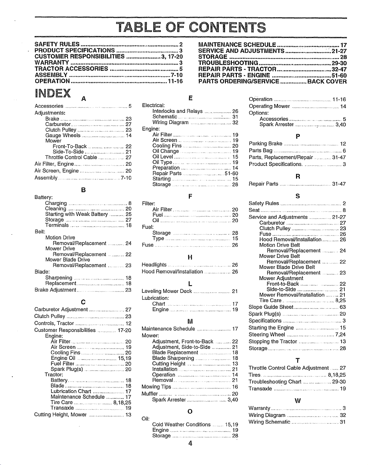
TA LE OF CONTENTS
SAFETY RULES .................. _ ......................................... 2
PRODUCT SPECIFICATIONS ...................................... 3
CUSTOMER RESPONSIBILITIES ..................... 3, 17-20
WARRANTY .................................................................. 3
TRACTOR ACCESSORIES .......................................... 5
ASSEMBLY .............................................................. 7-10
OPERATION ........................................................... 11-16
MAINTENANCE SCHEDULE ................ .................. _... 17
SERVICE AND ADJUSTMENTS ....... ,.,..,._, ..... L_.21-27
STORAGE ................................................................... 28
TROUBLESHOOTING ............................................ 29-30
REPAIR PARTS - TRACTOR ................................. 32-47
REPAIR PARTS- ENGINE .................................... 51-60
PARTS ORDERING/SERVICE ................ BACK COVER
INDEX
A
Accessories ........................................................5
Adjustments:
Brake .............................................................23
Carburetor ...................................................27
Clutch Pulley ..........................................23
Gauge Wheels ...........................................14
Mower
Front-To-Back ..................................22
Side-To-Side .....................................21
Throttle Control Cable ................... 27
Air Filter, Engine ..........................................20
Air Screen, Engine .......................................20
Assembly ........................................................7-10
B
Battery:
Charging ..........................................................8
Cleaning .......................................................20
Starting with Weak Battery ............25
Storage .......................................................27
Terminals ...................................................18
Belt:
Motion Drive
Removal/Replacement ................24
Mower Drive
Removal/Replacement .............22
Mower Blade Drive
Removal/Replacement ..............23
Blade:
Sharpening ................................................18
Replacement ............................................18
Brake Adjustment .........................................23
C
Carburetor Adjustment .....................................27
Clutch Pulley ..........................................................23
Controls, Tractor .............................................12
Customer Responsibilities ..................17-20
Engine:
Air Filter ................................................20
Air Screen ............................................19
Cooling Fins ...................................20
Engine Oil ...................................15,19
Fuel Filter. ..............................................20
Spark Plug(s) ....................................20
Tractor:
Battery .................................................18
Blade .........................................................18
Lubrication Chart ................................17
Maintenance Schedule ...............17
Tire Care .................................8,18,25
Transaxle ...............................................19
Cutting Height, Mower ................................13
E
Electrical:
interlocks and Relays ............................26
Schematic .........................................:...... 31
Wiring Diagram .....................................32
Engine:
Air Filter ......................................................19
Air' Screen ..............................................19
Cooling Fins ....................................................20
Oil Change ..............................................19
Oil Level ................................................15
Oil Type .................................................lg
Preparation ................................................14
Repair Parts .....................................51-60
Starting ......................................................15
Sterage ...................................................28
F
Filter:
Air Filter ..................................................20
Fuel ..................................................................20
Oil .....................................................................20
Fuel:
Storage ..................................................28
Type ..............................................................15
Fuse .....................................................................26
H
Headlights ....................................................26
Hood Removal/installation .............................26
L
Leveling Mower Deck ........................................21
Lubrication:
Chart ........................................................17
Engine ...........................................................19
M
Maintenance Schedule .....................................17
Mower:
Adjustment, Front4o*Back ..............22
Adjustment, Side4o-Side ....................21
Blade Replacement ................................18
Blade Sharpening ...............................18
Cutting Height .......................................13
Installation ................................................21
Operation .....................................................14
Removal ...................................................21
Mowing Tips .......................................................16
Muffle_ ...............................................................20
Spark Arrester ........................................3,40
Oii:
O
Cold Weather Conditions ...........15,1g
Engine ..............................................................19
Storage .............................................................28
4
Operation ................................................................11-16
Operating Mower. .....................................................14
Options:
Accessories .................................................5
Spark Arrester .......................................3,40
P
Parking Brake ........................................................12
Parts Bag ...........................................................................6
Parts, Replacement/Repair ................31-47
Product Specifications ..........................................3
R
Repair Parts ........................................................31-47
S
Safety Rules ..................................................................2
Seat .....................................................................................8
Service and Adjustments .......................21-27
Carburetor ................................................27
Clutch Pulley ..............................................23
Fuse ...............................................................26
Hood Removal/Installation ...................26
Motion Ddve Belt
Removal/Replacement ..............24
Mower Drive Belt
Removal/Replacement ..................22
Mower Blade Drive Belt
Remova!/Replacement ..............23
Mower Adjustment
Front-to-Back ...................................22
Side-to-Side ..........................................21
Mower Removal/Installation ............21
Tire Care ..............................................8,25
Slope Guide Sheet ........................................63
Spark Plug(s) .................................................20
Specifications ....................................................3
Starting the Engine ..........................................15
Steering Wheel ...............................................7,24
Stopping the Tractor •....................................13
Storage ...................................................................28
T
Throttle Control Cable Adjustment ...... 27
Tires .................................................................8,18,25
Troubleshooting Chart ..........................29-30
T_ansaxle ..............................................................19
W
Warranty ...........................................................................3
Wiring Diagram ..............................................32
Wiring Schematic .......................................................31
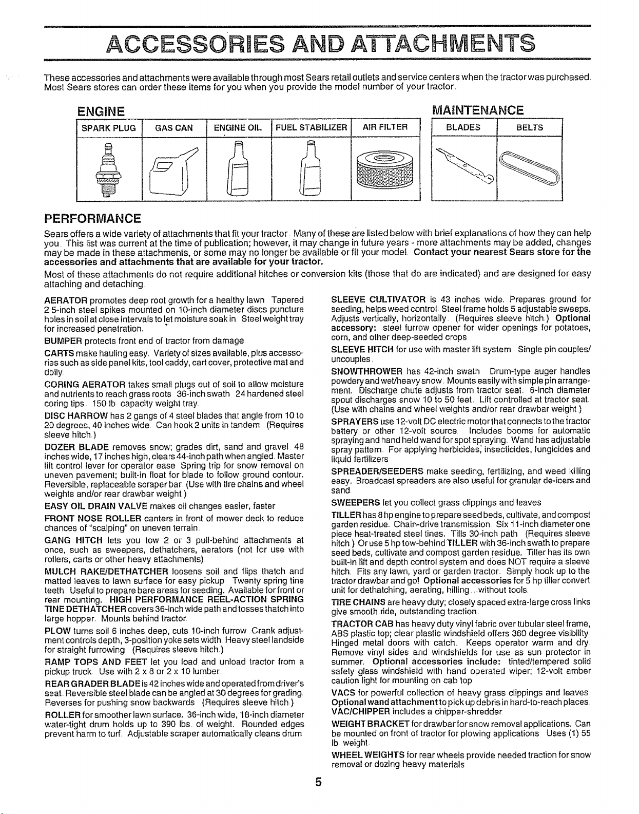
TheseaccessoriesandattachmentswereavailablethroughmostSearsretailoutletsandservicecenterswhenthetractorwaspurchased.
MostSearsstorescanordertheseitemsforyouwhenyouprovidethemodelnumberofyourtractor.
ENGINE
SPARK PLUG
0
GAS CAN ENGINE OIL FUEL STABILIZER AIR FILTER
MA|NTENANCE
BELTSBLADES
PERFORMANCE
Sears offers a wide variety of attacilments that fit your tractor Many of these are listed below with brief explanations of how they can help
you This list was current at timetime of publication; however, it may change in future years - more attachments may be added, changes
may be made in these attachments, or some may no longer be available or fit your model Contact your nearest Sears store for the
accessories and attachments that are available for your tractor,
Most of these attachments do not require additional hitches or conversion kits (those that do are indicated) and are designed for easy
attaching and detaching
AERATOR promotes deep root growth for a healthy lawn Tapered
2 5qnch steel spikes mounted on 10-inch diameter discs puncture
holes insoil at close intervalsto let moisture soak in Steel weight tray
for increased penetration. "_
BUMPER protects front end of tractor from damage
CARTS make hauling easy Varietyof sizes available, plus accesso-
ries such as side panel kits, tool caddy, cart cover, protective mat and
dolly.
CORING AERATOR takes small plugs out of soil to allow moisture
and nutrients to reach grass roots 36-inch swath 24 hardened steel
coring tips. I50 Ib capacity weight tray.
DISC HARROW has 2 gangs of 4 steel blades that angle from t0 to
20 degrees, 40 inches wide. Can hook 2 units in tandem (Requires
sleeve hitch )
DOZER BLADE removes snow; grades dirt, sand and gravel 48
inches wide, I7 inches high, clears 444nch path when angled Master
lift control lever for operator ease Spring trip for snow removal on
uneven pavement; built-in float for blade to follow ground contour.
Reversible, replaceable scraper bar (Use with tire chains and wheel
weights and/or rear drawbar weight )
EASY OIL DRAIN VALVE makes oil changes easier, faster
FRONT NOSE ROLLER canters in front of mower deck to reduce
chances of "scalping" on uneven terrain.
GANG HITCH lets you tow 2 or 3 pull-behind attachments at
once, such as sweepers, dethatchers, aerators (not for use with
rollers, carts or other heavy attachments)
MULCH RAKF-JDETHATCHER loosens soil and flips thatch and
matted leaves to lawn surface for easy pickup Twenty spring tine
teeth Useful to prepare bare areas forseeding. Available tor front or
rear mounting, HIGH PERFORMANCE REEL-ACTION SPRING
TINE DETHATCHER covers 36-inch wide path and tosses thatchinto
large hopper. Mounts behind tractor
PLOW turns soil 6 inches deep, cuts 10-inch furrow Crank adjust-
ment controls depth, 3-position yoke sets width Heavy steel landside
for straight furrowing (Requires sleeve hitch.)
RAMP TOPS AND FEET let you toad and unload tractor from a
pickup truck Use with 2 x 8 or 2 x 10 lumber
REAR GRADER BLADE is42 inches wide and operated from driver's
seat. Reversible steel blade can be angled at 30 degrees for grading.
Reverses for pushing snow backwards (Requires sleeve hitch)
ROLLER for smoother lawn surface. 36-inch wide, 18-inch diameter
water-tight drum holds up to 390 lbs. of weight. Rounded edges
prevent harm to turf. Adjustable scraper automatically cleans drum
SLEEVE CULTIVATOR is 43 inches wide. Prepares ground for
seeding, helps weed control- Steel frame holds 5 adjustable sweeps.
Adjusts vertically, horizontally (Requires sleeve hitch.) Optional
accessory: steel furrow opener for wider openings for potatoes,
corn, and other deep-seeded crops
SLEEVE HITCH for use with master lift system. Single pin couples!
uncouples.
SNOWTHROWER has 42-inch swath Drum-type auger handles
powdery and wet/heavy snow. Mounts easily with simple pin arrange-
ment. Discharge chute adjusts from tractor seat.. 6-inch diameter
spout discharges snow 10 to 50 feet. Lift controlled at tractor seat.
(Use with chains and wheel weights and/or rear drawbar weight )
SPRAYERS use 12wolt DC electric motor that connects to the {factor
battery or other 12-volt source includes booms for automatic
spraying and hand held wand for spot spraying. Wand has adjustable
spray pattern For applying herbicides; insecticides,fungicides and
liquid fertilizers
SPREADERtSEEDERS make seeding, fertilizing, and weed Idlling
easy. Broadcast spreaders are also usefu] forgranularde-icersand
sand
SWEEPERS let you collect grass clippings and leaves
TILLER has 8hp engine to prepare seed beds, cultivate, and compost
garden residue Chain*drive transmission Six 114nch diameterone
piece heat4reated steel tines. Tills 30-inch path (Requires sleeve
hitch ) Or use 5 hp tow-behind TILLER with 36-inch swath to prepare
seed beds, cultivate and compost garden residue. Tiller has its own
built-in lift and depth control system and does NOT require a sleeve
hitch Fits any lawn, yard or garden tracton Simply hook up to the
tractor drawbar and go! Optional accessories for 5 hp tiller convert
unit for dethatching, aerating, hilling without tools
TIRE CHAINS are heavy duly; closely spaced extra-large cross links
give smooth ride, outstanding traction
TRACTOR CAB has heavy duty vinyl fabric over tubular steel frame,
ABS plastic top; clear plastic windshield offers 360 degree visibility
Hinged metal doors with catch_ Keeps operator warm and dry
Remove vinyl sides and windshields for use as sun protector in
summer. Optional accessories include: tinted/tempered solid
safety glass windshield with hand operated wiper; 12-volt amber
caution light for mounting on cab top
VACS for powerful collection of heavy grass clippings and leaves
Optional wand attachment to pick up debris in hard4o-reach places
VAC/OHIPPER includes a chipper-shredder
WEIGHT BRACKET for drawbar for snow removal applications. Can
be mounted on front of tractor for plowing applications Uses (1) 55
Ib weight.
WHEEL WEIGHTS for rear wheels provide needed traction for snow
removal or dozing heavy materials
5
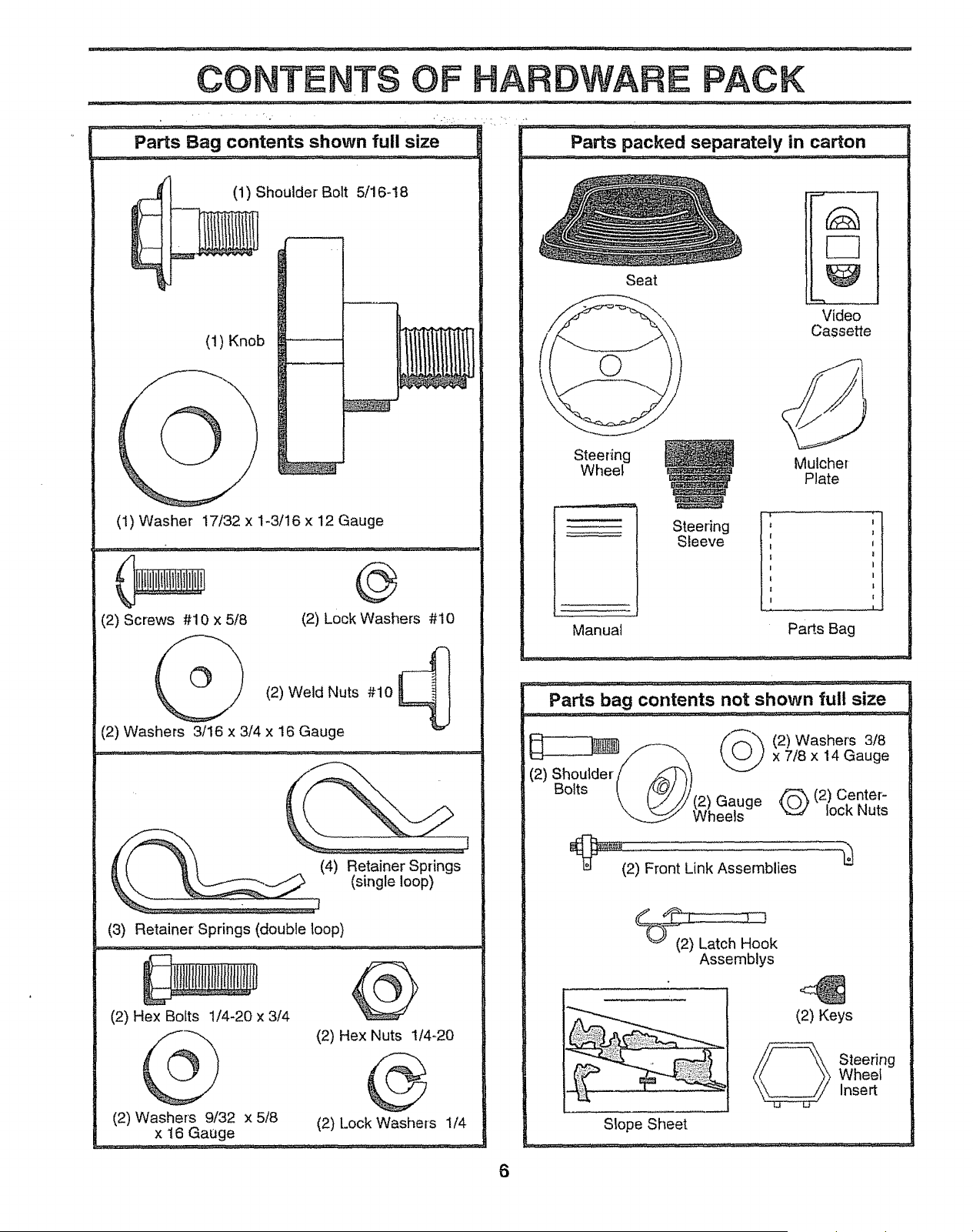
CONTENTS OF HARDWARE PACK
j/H_J:_ ,irl,_........ _........ _, , ............ _ ...... ........................ ,i_J ,:,l,,i,lll,,lll ............ i...... i.,
Parts Bag contents shown full size
(1) Shoulder Bolt 5/16-!8
(1) Knob
(1) Washer 17/32 x 1-3/16 x 12 Gauge
(2) Screws #10 x 5/8
(2) Lock Washers #10
(2) Weld Nuts #10 _ !
=IJ
(2) Washers 3/16 x 3/4 x 16 Gauge
__ (4) Retainer Springs
_] (single loop)
(3) Retainer Springs (double loop)
(2) Hex Bolts 1/4-20 x 3t4
(2) Hex Nuts 1t4-20
(2) Washers 9/32 x 5/8 (2) Lock Washers 1/4
x 16 Gauge
Parts packed separately in carton
Seat
Steering
Sleeve
Video
Cassette
Steering
Wheel
Manual
Mulcher
Plate
1
Pa_s Bag
Parts bag contents not shown full size
(2) Shoulder _\)
Bolts [ /_/ /j
\, [..///(2) Gauge
_Wheels
_(2) Front Link Assemblies
(2) Washers 3/8
x 7/8 x 14 Gauge
(2) Center-
lock Nuts
_ok
Assemblys
(2) Keys
Steering
Wheef
Insert
Slope Sheet
6
BLY
Your new tractor has been assembfed at the factory with exception of fhose parts left unassembled for shipping purposes.
To ensure safe and proper operation of your tractor all parts and hardware you assemble must be tightened securely,, Use
the correct tools as necessary to insure proper tightness..
TOOLS REQUIRED FOR ASSEMBLY
A socket wrench set will make assembly easier.. Standard
wrench sizes are listed.
(2) 7/!6" wrenches (1) Tire pressure gauge
(1) 9/I6" wrench (1) Utility knife
(1) 1/2" wrench (1) 3/4" socket w/drive ratchet
When right or Ieft hand is mentioned in this manual, it
means when you are in the operating position (seated
behind the steering wheel).,
TO REMOVE TRACTOR FROM CARTON
UNPACK CARTON
o Remove all accessible loose parts and parts cartons
from carton (See page 6)..
o Cut, from top to bottom, along lines on ati four corners
of carton, and lay panels flat,
• Remove mower and packing materials.
° Check for any additional loose parts or cartons and
remove.
BEFORE ROLLING TRACTOR OFFSKID
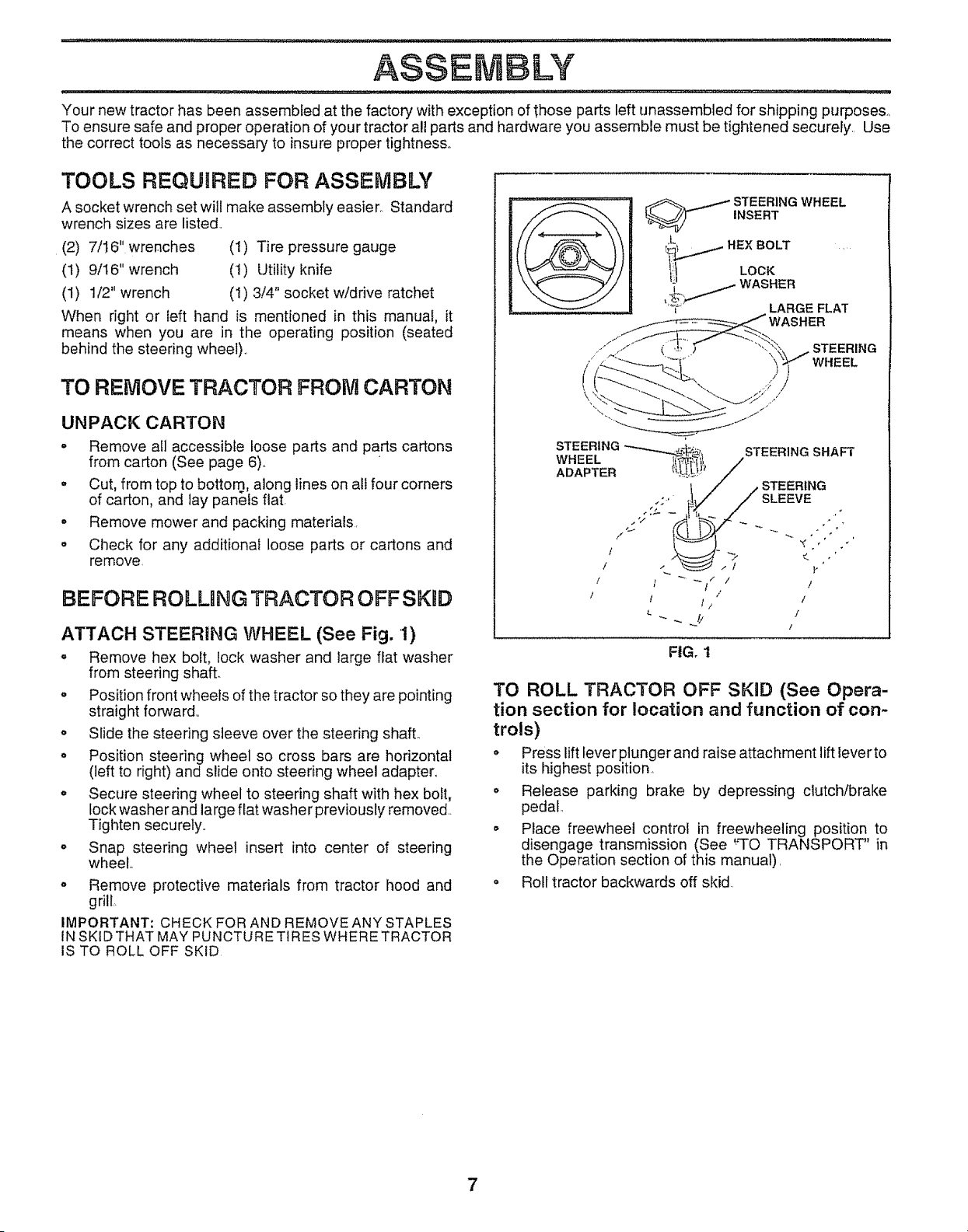
ATTACH STEERING WHEEL (See Fig. 1)
,' Remove hex bolt, lock washer and large flat washer
from steering shaft.
o Position front wheels of the tractor so they are pointing
straight forward,.
o Slide the steering sleeve over the steering shaft..
', Position steering wheel so cross bars are horizontal
(left to right) and slide onto steering wheel adapter..
° Secure steering wheel to steering shaft with hex bolt,
lock washer and large flat washer previously removed..
Tighten securely..
o Snap steering wheel insert into center of steering
wheel.,
,, Remove protective materials from tractor hood and
grill,,
IMPORTANT: CHECK FOR AND REMOVE ANY STAPLES
IN SKID THAT MAY PUNCTURE TIRES WHERE TRACTOR
IS TO ROLL OFF SKID
WHEEL
},
I I _ " I
I /
t I If" I
_ !! I
/
FIG. 1
TO ROLL TRACTOR OFF SKID (See Opera-
tion section for location and function of con-
trois)
° Press lift lever plunger and raise attachment lift lever to
its highest position,
o Release parking brake by depressing clutch/brake
pedal,
° Place freewheel control in freewheeling position to
disengage transmission (See "TO TRANSPORT" in
the Operation section of this manual),
o Roll tractor backwards off skid
7
ASSEM
., ........................n
HOW ,TO .SET UP YOUR TRACTOR
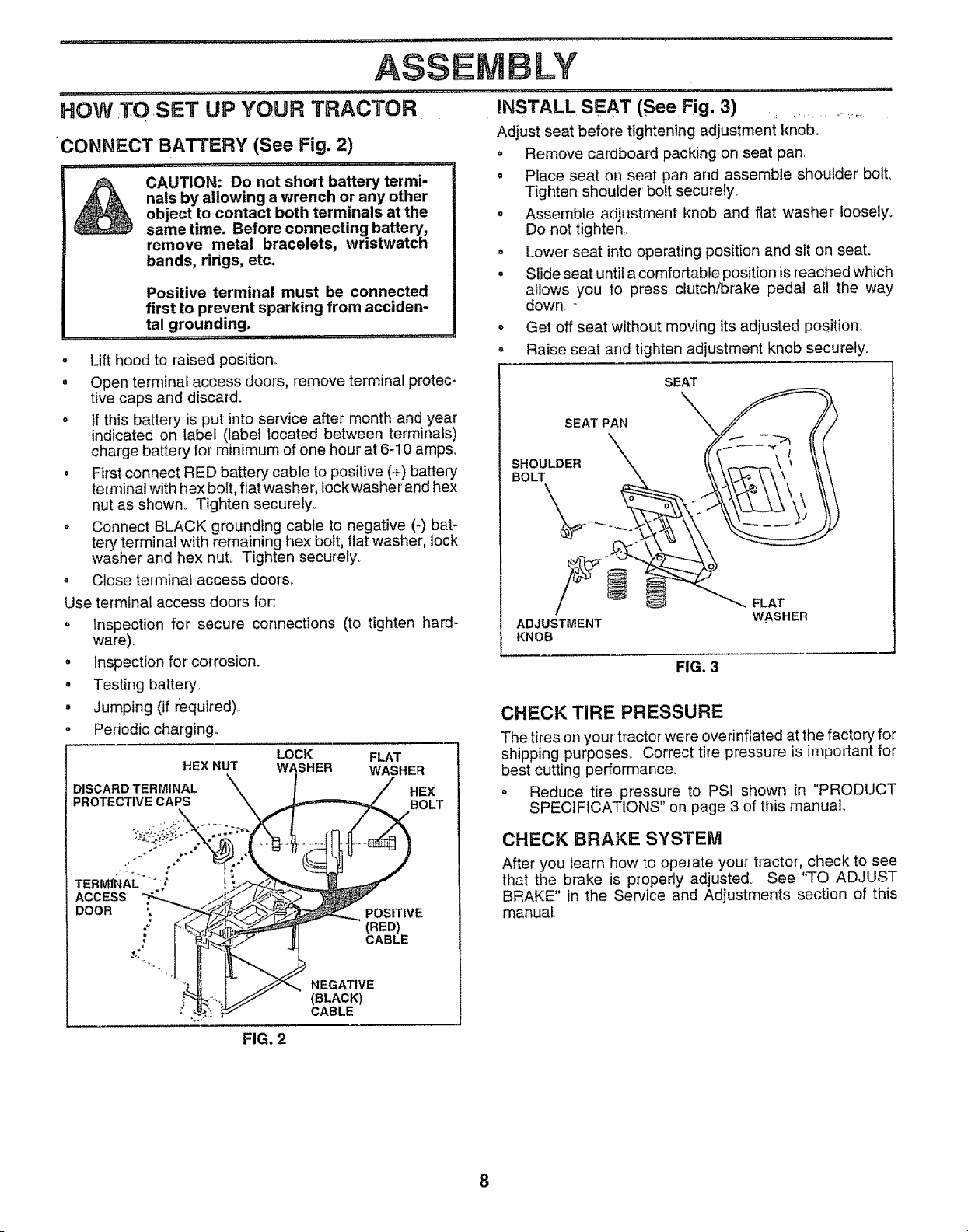
CONNECT BATTERY (See Fig. 2)
CAUTION: Do not short battery termi-
nals by allowing a wrench or any other
object to contact both terminals at the
same time. Before connecting battery,
remove metal bracelets, wristwatch
bands, rings, etc.
Positive terminal must be connected
first to prevent sparking from acciden-
tal grounding.
................ .. . ...... ......... ............................... .
o Lift hood to raised position,,
= Open terminal access doors, remove terminal protec-
tive caps and discard.
o tfthis battery is put into service after month and year
indicated on label (label located between terminals)
charge battery for minimum of one hour at 6-10 amps.
= First connect RED battery cable to positive (+) battery
terminal with hex bolt, flat washe r, lock washer and hex
nut as shown_ Tighten securely.
= Connect BLACK ground!ng cable to negative (-) bat-
tery terminal with remaining hex bolt, flat washer, lock
washer and hex nuL Tighten securely_
° Close terminal access door&
Use terminal access doors for:
° Inspection for secure connections (to tighten hard-
ware)°
° inspection for corrosion.
o Testing battery.
= Jumping (if required).
°
Periodic charging,,
LOCK FLAT
HEX NUT WASHER WASHER
LY
...... i. nill,llnl
INSTALL SEAT (See Fig. 3) .....
Adjust seat before tightening adjustment kn0b. .....' _'
o Remove cardboard packing on seat pan.,
= Place seat on seat pan and assemble shoulder bolt.
Tighten shoulder bolt securely.
o Assemble adjustment knob and flat washer loosely.
Do not tighten,
• Lower seat into operating position and sit on seat.
° Slide seat until a comfortable position is reached which
allows you to press clutch/brake pedal all the way
down,
o Get off seat without moving its adjusted position.
- Raise seat and tighten adjustment knob securely.
SEAT
SEAT PAN
SHOULDER
BOLT
ADJUSTMENT
KNOB
FIG. 3
FLAT
WASHER
CHECK TIRE PRESSURE
The tires on your tractor were overinflated at the factory for
shipping purposes,. Correct tire pressure is important for
best cutting performance.
= Reduce tire pressure to PS1 shown in "PRODUCT
SPECIFICATIONS" on page 3 of this manual,,
CHECK BRAKE SYSTEM
After you learn how to operate your tractor, check to see
that the brake is properly adjusted. See 'q'O ADJUST
BRAKE" in the Service and Adjustments section of this
manual
FIG, 2
8
LY
I:l:ll_/_0U_l;_lll:lI " ' I" I ....
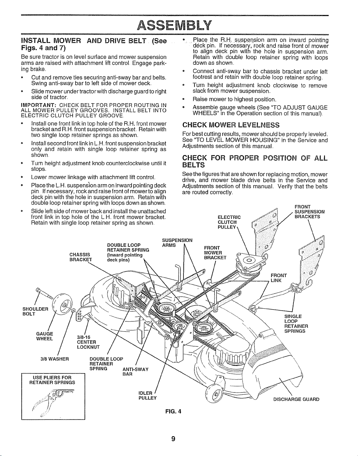
INSTALL MOWER AND DRIVE BELT (See
Figs. 4 and 7)
Be sure tractor is on tevel surface and mower suspension
arms are raised with attachment lift control Engage park-
ing brake.. =
= Cut and remove ties securing anti-sway bar and belts.
Swing anti-sway bar to left side of mower deck, .
• Slide mower under tractor with discharge guard to right
side of tractor.
IMPORTANT: CHECK BELT FOR PROPER ROUTING IN
ALL MOWER PULLEY GROOVES. INSTALL BELT INTO
ELECTRIC CLUTCH PULLEY GROOVE
° Place the B,H,..Suspension arm on inward pointing
.....deck'pino If necessary, rock and raise front of mower
to align deck pin with the hole in suspension arm,
Retain with double loop retainer spring with loops
down as shown.
o
Connect anti-sway bar to chassis bracket under left
footrest and retain with double loop retainer spring.
Turn height adjustment knob clockwise to remove
slack from mower suspension°
Raise mower to highest position..
Assemble gauge wheels (See "TO ADJUST GAUGE
WHEELS" in the Operation section of this manual).
o Install one front link in top hole of the R.H. front mower
bracket and R,.H..front suspension bracket. Retain with
two single loop retainer springs as shown,.
- Install second front link in L.H. front suspension bracket
only and retain with single loop retainer spring as
shown.
o Turn height adjustment knob counterclockwise until it
stops.
• Lower mower linkage with attachment lift control..
• Place the LH. suspension arm on inward pointing deck
pin. If necessary, rock and raise front of mowerto align
deck pin with the hole in suspension arm,. Retain with
double loop retainer spring with loops down as shown.
o Slide left side of mower back and install the unattached
front link in top hole of the L.H. front mower bracket.
Retain with single loop retainer spring as shown.
DOUBLE LOOP
RETAINER SPRING
CHASSIS (Inward pointing
BRACKET deck pins)
SUSPENSION
ARMS
CHECK MOWER LEVELNESS
For best cutting results, mower should be properly leveled.
See "TO LEVEL MOWER HOUSING" in the Service and
Adjustments section of this manual,
CHECK FOR PROPER POSITION OF ALL
See the figures that are shown for replacing motion, mower
drive, and mower blade drive belts in the Service and
Adjustments section of this manual.. Verify that the belts
are routed correctly.
ELECTRIC
CLUTCH
PU LLEY
FRONT
SUSPENSION
BRACKETS
FRONT
MOWER
BRACKET
FRONT
LINK
SHOULDER
BOLT
GAUGE
WHEEL
/
318WASHER
USE PLIERS FOR
RETAINER SPRINGS
318-16
CENTER
LOCKNUT
/
DOUBLE LOOP
RETAINER
SPRING ANTI-SWAY
BAR
IDLER /
PULLEY
FIG. 4
\\
SINGLE
LOOP
RETAINER
SPRINGS
DISCHARGE GUARD
9
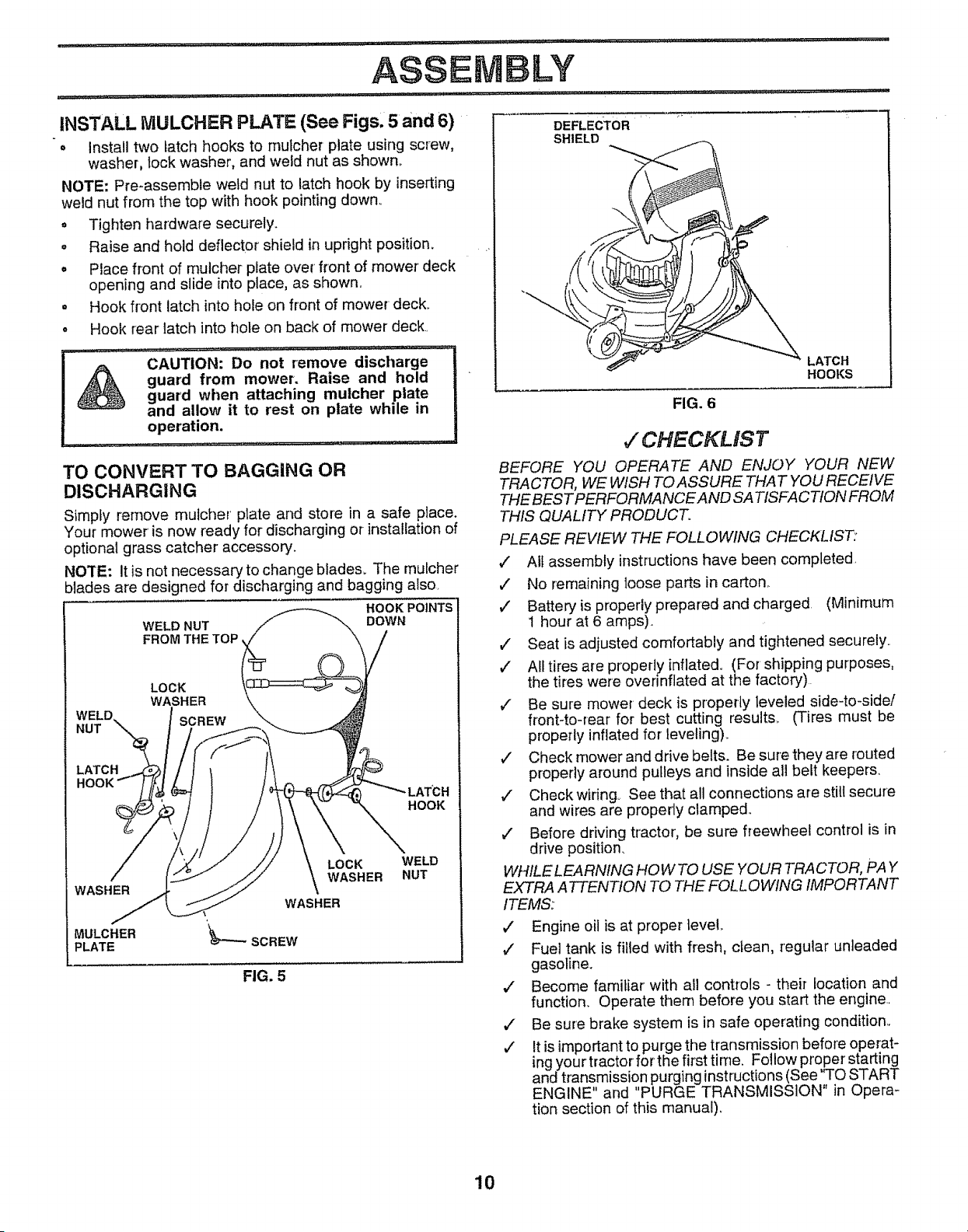
INSTALL IVlULCHER PLATE (See Figs. 5 and 6)
o Install two latch hooks to rnutcher plate using screw,
washer, rockwasher, and weld nut as shown,
NOTE: Pre-assembte weld nut to latch hook by inserting
weld nut from the top with hook pointing down_
o Tighten hardware securely.
o Raise and hold deflector shield in upright position.
° Place front of mu/cher plate over front of mower deck
opening and slide into place, as shown.
o Hook front latch into hole on front of mower deck_
• Hook rear latch into hole on back of mower deck.
DEFLECTOR
SHIELD
I A CAUTION: D0notrem0ve discharge-_
,_ guard from mower. Raise and hold I
guard when attaching mulcher plate |
and allow it to rest on plate while in
operation.
TO CONVERT TO BAGGING OR
DISCHARGING
Simply remove mulcher plate and store in a safe place.
Your mower is now ready for discharging or-installation of
optional grass catcher accessory.
NOTE: It is not necessary to change blades_ The mulcher
blades are designed for discharging and bagging also.
WELD NUT
FROM THE TOP,
HOOK POINTS
DOWN
LOCK
WASHER
SCREW
LATCH
HOOK
H
HOOK
WASHER
MULCHER
PLATE
LOCK
WASHER
WASHER
_'---SCREW
FIG. 5
WELD
NUT
FIG. 6
LATCH
HOOKS
J" CHECKLIST
BEFORE YOU OPERATE AND ENJOY" YOUR NEW
TRACTOR, WE WISH TO ASSURE THAT YOU RECEIVE
THE BEST PERFORMANCE AND SA TISFACTIOIV FROM
THIS QUALITY PRODUCT.
PLEASE REVIEW THE FOLLOWING CHECKLIST:
,/ All assembly instructions have been completed.
v" No remaining loose parts in carton,.
,/ Battery is properly prepared and charged (Minimum
1 hour at 6 amps).
¢" Seat is adjusted comfortably and tightened securely..
v" Alttires are properly inflated., (For shipping purposes,
the tires were overinflated at the factory)
¢ Be sure mower' deck is properly leveled side-to-side/
front-to-rear for best cutting results.. (Tires must be
properly inflated for leveling)..
¢' Check mower and drive belts. Be sure they are routed
properly around pulleys and inside all belt keepers.
,/ Check wiring° See that all connections are still secure
and wires are properly clamped.
v" Before driving tractor, be sure freewheel control is in
drive position.
WHILELEARNING HOWTO USE YOUR TRACTOR, PAY
EXTRA A TTENTION TO THE FOLLOWING IMPORTANT
ITEMS:
,/ Engine oil is at proper level
¢" Fuel tank is filled with fresh, clean, regular unleaded
gasoline.
,/ Become familiar with all controls - their location and
function. Operate them before you start the engine..
,/ Be sure brake system is in safe operating condition.
v' It is important to purge the transmission before operat-
ing your tractor for the first time. Follow proper starting
and transmission purging instructions (See 'TO START
ENGINE and PURGE TRANSMISSION in Opera-
tion section of this manual)_
10
,:llll ........ ,...... i i
OPERATUON
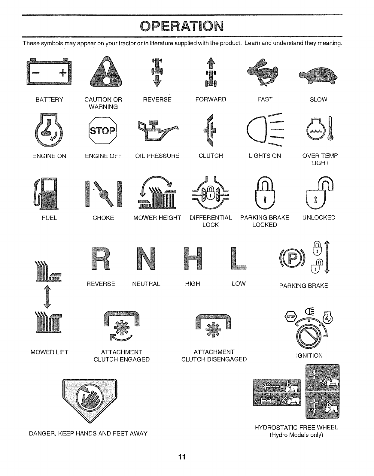
These symbols may appear on your tractor or in literature supplied with the producL Learn and understand they meaning.,
BATTERY CAUTION OR REVERSE FORWARD FAST
WARNING
ENGINE ON ENGINE OFF OIL PRESSURE CLUTCH LIGHTS ON
SLOW
OVER TEMP
LIGHT
CHOKEFUEL MOWER HEIGHT DIFFERENTIAL
LOCK
PARKING BRAKE
LOCKED
UNLOCKED
REVERSE NEUTRAL HIGH LOW
PARKING BRAKE
MOWER LIFT ATTACHMENT
CLUTCH ENGAGED
ATTACHMENT
CLUTCH DISENGAGED
IGNITION
DANGER, KEEP HANDS AND FEET AWAY
HYDROSTATIC FREE WHEEL
(Hydro Models only)
11
OPERATION
_"'I'IT'_'¸ "_ ................ '............... I'l ................. I/_ "ll"l
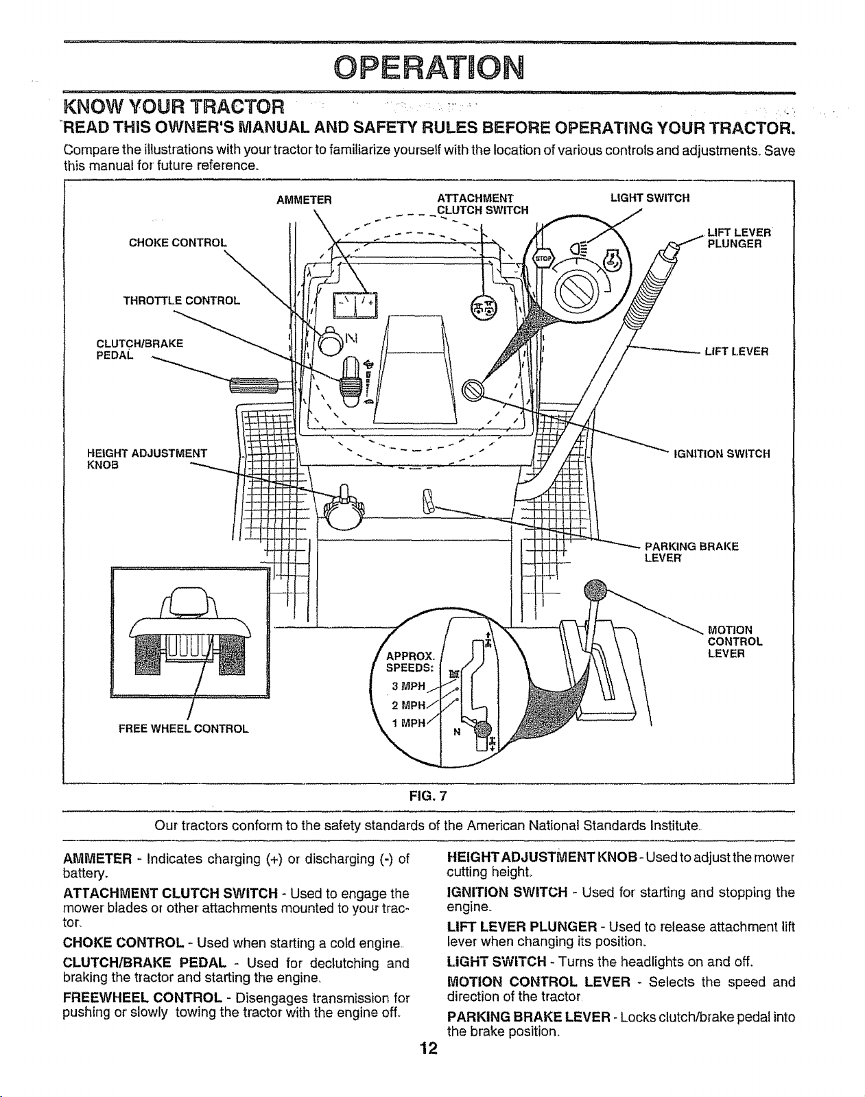
KNOW YOUR TRACTOR ...... _ ......_ ...... ,..
"READ THiS OWNER'S MANLIAL AND SAFETY RULES BEFORE OPERATING YOUR TRACTOR.
Compare the illustrations with your tractor to familiarize yourself with the location of various controls and adjustments° Save
this manual for future reference.
CHOKE CONTROL
-\
THROTTLE CONTROL
CLUTCH/BRAKE
PEDAL
HEIGHT ADJUSTMENT
KNOB
AMMETER ATTACHMENT LIGHT SWITCH
_ L,L.UTCH SWITCH
APPROX.
SPEEDS:
3 MPH
, LIFT LEVER
PLUNGER
LIFT LEVER
IGNITION SWITCH
PARKING BRAKE
LEVER
MOTION
CONTROL
LEVER
FREE WHEEL CONTROL
FIG. 7
Our tractors conform to the safety standards of the American National Standards Institute,
AMMETER - Indicates charging (+) or discharging (-) of
battery.
ATTACHMENT CLUTCH SWITCH - Used to engage the
mower' blades or other- attachments mounted to your trac-
tor.
CHOKE CONTROL - Used when starting a cold engine,,
CLUTCH/BRAKE PEDAL - Used for declutching and
braking the tractor and starting the engine,
FREEWHEEL CONTROL - Disengages transmission for
pushing or slowly towing the tractor with the engine off_
12
HEIGHT ADJUSTMENT KNOB - Used to adjust the mower
cutting heighL
IGNITION SWITCH - Used for' starting and stopping the
engine.
LIFT LEVER PLUNGER - Used to release attachment lift
lever when changing its position.
LIGHT SWITCH - Turns the headlights on and off.
iVlOTION CONTROL LEVER - Selects the speed and
direction of the tractor,
PARKING BRAKE LEVER - Locks clutch/brake pedal into
the brake position.
OPERATtO
The operation of any tractor can result in foreign objects thrown into the eyes, which can result
in severe eye damage. Always wear safety glasses or eye shields while operating your tractor
or performing any adjustments or repairs. We recommend a wide vision safety mask over the
spectacles or standard safety glasses.
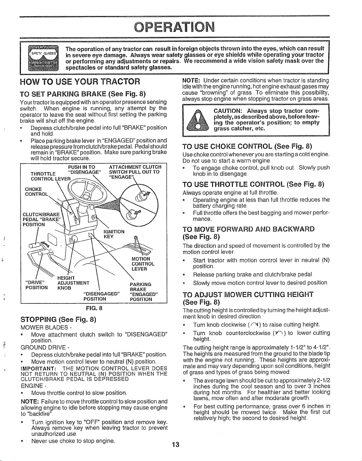
flOW TO USE YOUR TRACTOR
TO SET PARKING BRAKE (See Fig. 8)
Your tractor is equipped with an operator presence sensing
switch. When engine is running, any attempt by the
operator to teave the seat without first setting the parking
brake wilt shut off the engine..
o Depress clutch/brake pedal into full "BRAKE" position
and hold
• Place parking brake lever in "ENGAGED" position and
release pressure from clutch/brake pedal,. Pedal should
remain in "BRAKE" position.. Make sure parking brake
will hold tractor secure..
PUSH IN TO ATTACHMENT CLUTCH
THROTTLE "DISENGAGE" SWITCH PULL OUT TO
CONTROL LEVER
CHOKE
CONTROL
CLUTCHfBRAKE
PEDAL "BRAKE"
POSITION
IGNITION
MOTION
CONTROL
LEVER
HEIGHT
"DRIVE" ADJUSTMENT PARKING
POSITION KNOB BRAKE
"DISENGAGED .... ENGAGED"
POSITION POSITION
FIG. 8
STOPPING (See Fig. 8)
MOWER BLADES -
o Move attachment clutch switch to "DISENGAGED"
position.
GROUND DRIVE
= Depress clutch/brake pedal into full "BRAKE" position.
o Move motion control lever to neutral IN) position..
IMPORTANT: THE MOTION CONTROL LEVER DOES
NOT RETURN TO NEUTRAL IN) POSITION WHEN THE
CLUTCH/BRAKE PEDAL IS DEPRESSED
ENGINE -
• Move throttle control to slow position.
NOTE: Failure to move throttle control to slow position and
allowing engine to idle before stopping may cause engine
to "backfire"
- Turn ignition key to "OFF" position and remove key.
Always remove key when leaving tractor to prevent
unauthorized use,
° Never use choice to stop engine,.
NOTE: Under certain conditions when tractor is standing
idle with the engine running, hot engine exhaust gases may
cause "browning" of grass To eliminate this possibility,
always stop engine when stopping tractor on grass areas..
CAUTION: Always stop tractor com-
pletely, as described above, before leav-
ing the operator's position; to empty
grass catcher, etc.
TO USE CHOKE CONTROL (See Fig. 8)
Use choke control whenever you are sta rting a cold engine..
Do not use to start a warm engine.
= To engage choke control, pull knob out. Slowly push
knob in to disengage.
TO USE THROTTLE CONTROL (See Fig. 8)
Always operate engine at full throttle..
= Operating engine at less than full throttle reduces the
battery charging rate
o Full throttle offers the best bagging and mower perfor-
mance..
TO MOVE FORWARD AND BACKWARD
(See Fig. 8)
The direction and speed of movement is controlled by the
motion control lever.
o Start tractor with motion control lever in neutral (N)
position,,
o Release parking brake and clutch/brake pedal,
o Slowly move motion control lever to desired position
TO ADJUST MOWER CUTTING HEIGHT
(See Fig, 8)
The cutting height is controlled by turning the height adjust-
ment knob in desired direction..
o Turn knob clockwise (f-'1) to raise cutting height°
o Turn knob counterclockwise (1-_)to lower cutting
height,
The cutting height range is approximately i-1/2" to 4-1/2".
The heights are measured from the ground to the blade tip
with the engine not running.. These heights are approxi-
mate and may vary depending upon soil conditions, height
of grass and types of grass being mowed.
o The average lawn should be cut to approximately 2-1/2
inches during the cool season and to over 3 inches
during hot months. For healthier and better looking
lawns, mow often and after moderate growth.
o For best cutting performance, grass over 6 inches in
height should be mowed twice. Make the first cut
relatively high; the second to desired height,
13
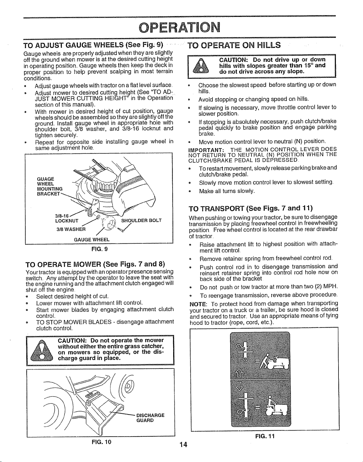
TO ADJUST GAUGE WHEELS (See Fig.9)
Gauge wheels are properly adjusted when they are slightly
off the ground when mower is at the desired cutting height
in operating position. Gauge wheels then keep the deck in
proper position to help prevent scalping in most terrain
condition&
o Adjust gauge wheels with tractor on a fiat level surface
° Adjust mower to desired cutting height (See "TO AD-
JUST MOWER CUTTING HEIGHT' in the Operation
section of this manual).
o With mower in desired height of cut position, gauge
wheels should be assembled so they are slightly off the
ground. Install gauge wheel in appropriate hole with
shoulder bolt, 3/8 washer, and 3/8q6 tocknut and
tighten securely.
o Repeat for opposite side installing gauge wheel in
same adjustment hole.
GUAGE
WHEEL
MOUNTING
318-16 J
LOCKNUT
3t8 WASHER
GAUGE WHEEL
FIG. 9
SHOULDER BOLT
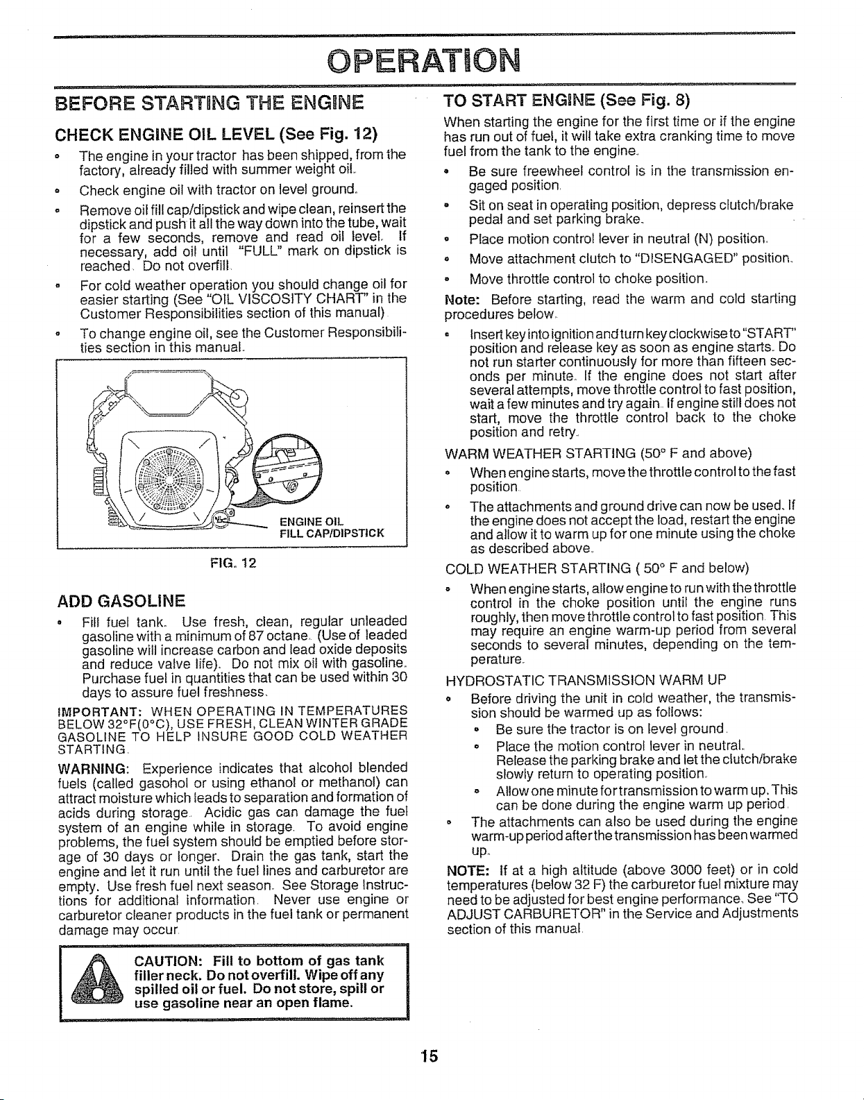
TO OPERATE MOWER (See Figs. 7 and 8)
You rtractor is equipped with an operator presence sensing
switch Any attempt by the operator to leave the seat with
the engine running and the attachment clutch engaged will
shut off the engine
o Select desired height of cut°
= Lower mower with attachment lift control
o Start mower blades by engaging attachment clutch
control
• TO STOP MOWER BLADES - disengage attachment
clutch control
;i; : CAUTION _¸¸¸¸ _rT Do",ll ,,,notlll ......operate_'_l'"l .... the mowerl', ,,, i, ii,,,,i,,,,i 1
without either'the entire grass catcher, |
on mowers so equipped, or the dis- |
charge guard in place. |
OPERATIO
TO OPERATE ON HILLS
F& CAUTION: Do not'drive up or down ...........j
hills with slopes greater than 15 ° and
_e_ do not drive across any slope
• ....... _ _ .... .J
° Choose the slowest speed before starting up or down
hills°
o Avoid stopping or changing speed on hills
o If slowing is necessary, move throttle control lever to
slower position.
o If stopping is absolutely necessary, push clutch/brake
edal quickly to brake position and engage parking
rake_
° Move motion control lever to neutral (N) position.
IMPORTANT; THE MOTION CONTROL LEVER DOES
NOT RETURN TO NEUTRAL (N) POSITION WHEN THE
CLUTCH/BRAKE PEDAL IS DEPRESSED
o To restart movement, slowly release parking brake and
crutch/brake pedal
° Slowly move motion control lever to slowest setting
o Make all turns slowly.
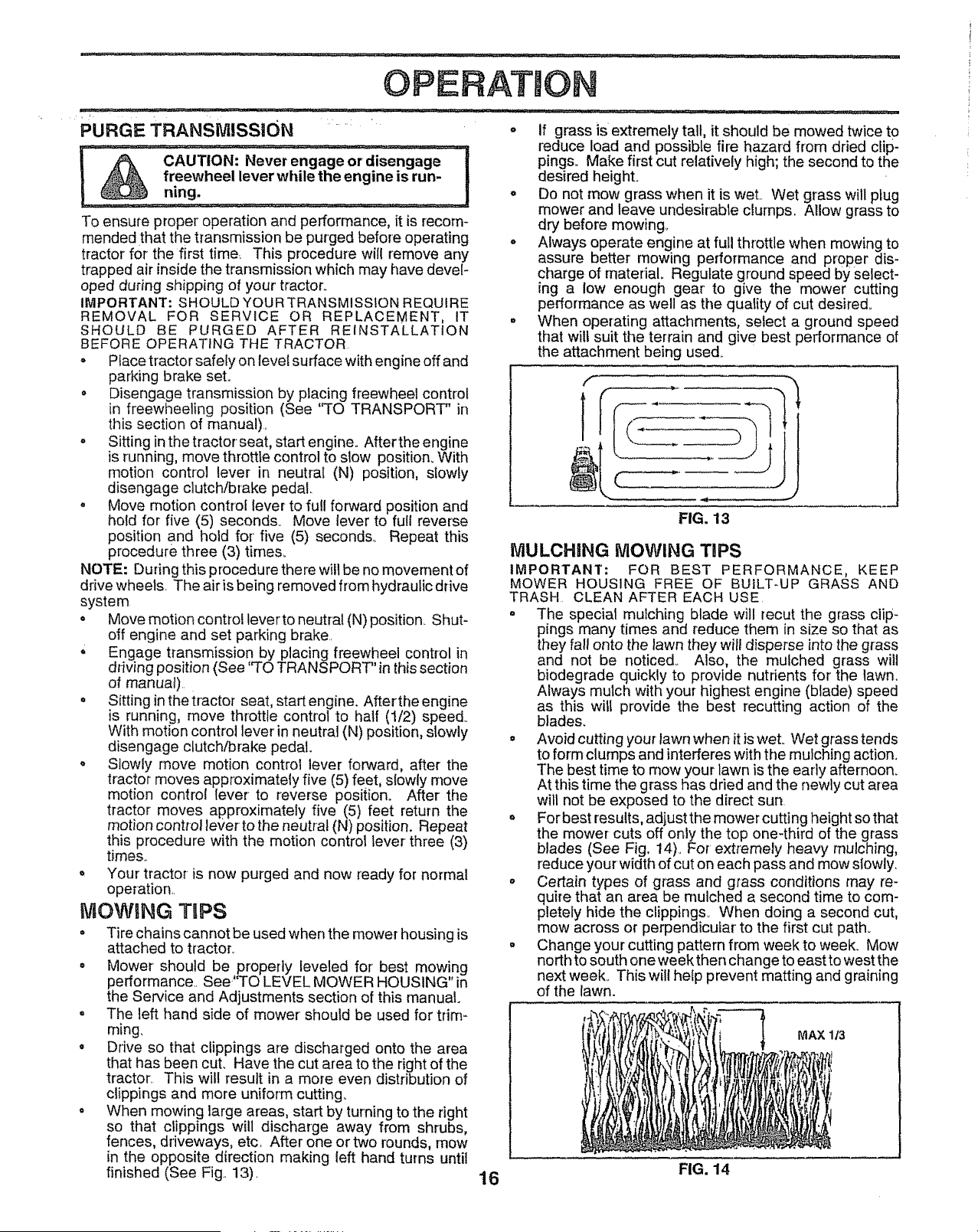
TO TRANSPORT (See Figs. 7 and 11)
When pushing or towing your tractor, be sure to disengage
transmission by placing freewheel control in freewheeling
position Free wheel control is located at the rear drawbar
of tractor
° Raise attachment lift to highest position with attach-
ment lift control,
o
o
Remove retainer spring from freewheel control rod,
Push control rod in to disengage transmission and
reinsert retainer spring into control rod hole now on
back side of the bracket•
o Do not push or tow tractor at more than two (2) MPHo
o To reengage transmission, reverse above procedure
NOTE: To protect hood from damage when transporting
your tractor on a truck or a trailer', be sure hood is closed
and secured to tractor. Use an approphate means of tying
hood to tractor (rope, cord, etc).
DISCHARGE
GUARD
FIG. 11
FIG. 10 14
OPERATION
BEFORE STARTnNG THE ENGINE
CHECK ENGINE OIL LEVEL (See Fig. 12)
• The engine in your tractor has been shipped, from the
factory, already filled with summer weight oil..
• Check engine oil with tractor on level ground.
° Remove oil fill cap/dipstick and wipe clean, reinsert the
dipstick and push it all the way down into the tube, wait
for a few seconds, remove and read oil level, If
necessary, add oil until "FULL" mark on dipstick is
reached. Do not overfill,
. For cold weather operation you should change oil for
easier starting (See "OlL VISCOSITY CHART' in the
Customer Responsibilities section of this manual)
To change engine oil, see the Customer Responsibili-
ties section in this manual,,
t_ ENG NE
__ OIL
FILL CAP/DIPSTICK
FIG,, 12
ADD GASOLINE
Fill fuel tank° Use fresh, clean, regular unleaded
gasoline with a minimum of 87 octane, (Use of leaded
gasoline wilt increase carbon and lead oxide deposits
and reduce valve life). Do not mix oil with gasoline..
Purchase fuel in quantities that can be used within 30
days to assure fuel freshness.
IMPORTANT: WHEN OPERATING IN TEMPERATURES
BELOW 32°F(0°C), USE FRESH, CLEAN WINTER GRADE
GASOLINE TO HELP INSURE GOOD COLD WEATHER
STARTING
WARNING: Experience indicates that alcohol blended
fuels (called gasohol or using ethanol or methanol) can
attract moistu re which leads to separation and formation of
acids during storage Acidic gas can damage the fuel
system of an engine while in storage. To avoid engine
problems, the fuel system should be emptied before stor-
age of 30 days or longer. Drain the gas tank, start the
engine and tet it run until the fuel Iines and carburetor are
empty. Use fresh fuel next season. See Storage Instruc-
tions for additional information Never use engine or
carburetor cleaner products in the fuel tank or permanent
damage may occur
i& AUTION: Fill to bottom of gas tank
filler neck, Do not overfill. Wipe off any
spilled oil or fuel, Do not store, spill or
use gasoline near an open flame.
.............. i i , ,i,,,,nl,u
TO START ENGRNE (See Fig. 8)
When starting the engine for the first time or if the engine
has run out of fuel, it wilt take extra cranking time to move
fuel from the tank to the engine..
• Be sure freewheel control is in the transmission en-
gaged position
o Sit on seat in operating position, depress clutch/brake
pedal and set parking brake_
o Place motion control lever in neutral (N) position,
o Move attachment clutch to "DISENGAGED" position..
o Move throttle control to choke position.
Note: Before starting, read the warm and cold starting
procedures below.
= Insert key into ignition and turn key clockwise to "START'
position and release key as soon as engine starts.. Do
not run starter continuously for more than fifteen sec-
onds per minute° If the engine does not start after
several attempts, move throttle control to fast position,
wait a few minutes and try again.. If engine still does not
start, move the throttle control back to the choke
position and retry..
WARM WEATHER STARTING (50 ° F and above)
o When engine starts, move the throttle control to the fast
position
o The attact_ments and ground drive can now be used.. If
the engine does not accept the load, restart the engine
and allow it to warm up for one minute using the choke
as described above..
COLD WEATHER STARTING ( 50 ° F and below)
o When engine starts, allow engine to run with the throttle
control in the choke position until the engine runs
roughly, then move throttle control to fast position This
may require an engine warm-up period from several
seconds to several minutes, depending on the tem-
perature.
HYDROSTATIC TRANSMISSION WARM UP
o Before driving the unit in cold weather, the transmis-
sion should be warmed up as follows:
• Be sure the tractor is on level ground,
o Place the motion control lever in neutral,,
Release the parking brake and let the clutch/brake
slowly return to operating position,
o Atlowone minute for transmission to warm up, This
can be done during the engine warm up period,
o The attachments can also be used during the engine
warm-up period after the transmission has been warmed
up.,
NOTE: If at a high altitude (above 3000 feet) or in cold
temperatures (below 32 F) the carburetor fuel mixture may
need to be adjusted for best engine performance. See "TO
ADJUST CARBURETOR" in the Service and Adjustments
section of this manual,
15
OPERATIO
i /i ¸ - _'_'_ -: ...........................
TRANSMiSSiON " :
PURGE
To ensure proper' operation and performance, it is recom-
mended that the transmission be purged before operating
tractor for the first time_ This procedure will remove any
trapped air inside the transmission which may have devel-
oped during shipping of your' tractor°
IMPORTANT: SHOULD YOUR TRANSMISSION REQUIRE
REMOVAL FOR SERVICE OR REPLACEMENT, IT
SHOULD BE PURGED AFTER REINSTALLATION
BEFORE OPERATING THE TRACTOR
• Place tractor safely on level surface with engine off and
parking brake set.
° Disengage transmission by placing freewheel control
in freewheeling position (See '`TO TRANSPORT" in
this section of manual),
. Sitting in the tractor seat, start engine. After the engine
is running, move throttle control to slow position. With
motion control lever in neutral (N) position, slowly
disengage clutch/brake pedal.
. Move motion control lever to full forward position and
hold for five (5) seconds° Move lever to full reverse
position and hold for' five (5) seconds.. Repeat this
procedure three (3) times_
NOTE: During this procedure there will be no movement of
drive wheels. The air is being removed from hydraulic drive
system
o Move motion contro! leverto neutral (N) position. Shut-
off engine and set parking brake.
,; Engage transmission by placing freewheel control in
driving position (See '70 TRANSPORT" in this section
of manual)..
o Sitting in thetractor seat, start engine. Aftertheengine
is running, move throttle control to half (1/2) speed..
With motion control lever in neutral (N) position, slowly
disengage clutch/brake pedal.
o Slowly move motion control lever forward, after the
tractor moves approximately five (5) feet, slowly move
motion control lever to reverse position. After the
tractor moves approximately five (5) feet return the
motion control lever to the neutral (N) position. Repeat
this procedure with the motion control lever three (3)
times.
o Your tractor is now purged and now ready for normal
operation..
MOWING TIPS
- Tire chains cannot be used when the mower housing is
attached to tractor,
° Mower should be,properly leveled for best mow!ng
performance,. See 'TO LEVEL MOWER HOUSING in
the Service and Adjustments section of this manual.
° The left hand side of mower should be used for trim-
ruing,
• Drive so that clippings are discharged onto the area
that has been cut. Have the cut area to the right of the
tractor. This will result in a more even distribution of
clippings and more uniform cutting_
o When mowing large areas, start by turning to the right
so that clippings will discharge away from shrubs,
fences, driveways, etc, After one or two rounds, mow
in the opposite direction making left hand turns until
finished (See Fig.. 13).
o
...... ........ ,_1¸ ii i, r,:, ,, .............. ............ =........
If grass is extremely tall, it should be mowed twice to
['educe load and possible fire hazard from dried clip-
pings. Make first cut relatively high; the second to the
desired height.
. Do not mow grass when it is wet.. Wet grass will plug
mower and leave undesirable clumps, Allow grass to
dry before mowing_
° Always operate engine at full throttle when mowing to
assure better' mowing performance and proper dis-
charge of rnaterial. Regulate ground speed by select-
ing a low enough gear' to give the mower cutting
performance as well as the quality of cut desired,.
. When operating attachments, select a ground speed
that will suit the terrain and give best performance of
the attachment being used..
f
1
FIG. 13
MULCHING MOWING TiPS
IMPORTANT: FOR BEST PERFORMANCE, KEEP
MOWER HOUSING FREE OF BUlL%UP GRASS AND
TRASH. CLEAN AFTER EACH USE
° The special mulching blade will recur the grass clip-
pings many times and reduce them in size so that as
they fall onto the lawn they will disperse into the grass
and not be noticed° Also, the mulched grass will
biodegrade quickly to provide nutrients for the lawn,
Always mulch with your highest engine (blade) speed
as this wilt provide the best recutting action of the
blades.
o Avoid cutting your lawn when it is weL Wet grass tends
to form clumps and interferes with the mulching action.,
The best time to mow your lawn is the early afternoon.
At this time the grass has dried and the newly cut area
will not be exposed to the direct sun.
o For best results, adjust the mower cutting height so that
the mower cuts off only the top one-third of the grass
blades (See Fig. 14).. For' extremely heavy mulching,
reduce your width of cut on each pass and mow slowly,
o Certain types of grass and grass conditions may re-
quire that an area be mulched a second time to com-
pletely hide the clippings. When doing a second cut,
mow across or perpendicular to the first cut path.
o Change your cutting pattern from week to week. Mow
north to south one week then change to east to west the
next week.. This wil! help prevent matting and graining
of the lawn.
MAX 1t3
16 FIG. 14
CUSTOMER IRESPONSmlBIL iTIES
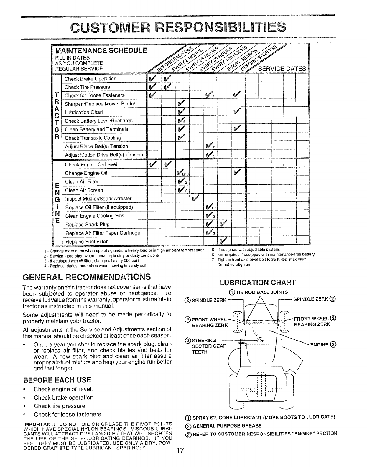
....MAa"TE.A.CESC,EDULE ...... "
FILL IN DATES /_._"_. _._4_"
AsYOUCOMPL E .......
REGULARSERVICE .__f/_/J£,_,_,_" SERVICE DATES
Check BrakeOperation 6##
Check Tire'"'Pressure t_ 6_
T '_'"Checkfor Loose Fastener's
R SharpenlReplac'e"'MowerB'i'ades..... , =
A# Lubrication,,,Chart ........ ...... _ ...............
T Check Battery" Level(Recharge ................... 6446 ........
0 CleanBattery andTerminals 6#4'
R CheckTransaxleCooling
AdjustBladeBett(s)Tension
AdjustMotionDrive Belt(s)Tension
....... : , ,,,,,,,,,,,, :: : . ........
Check Engine Oit Level $f _4'
Change,,Engineoil .........................._t2.3 ............
Clean Air Filter 6/'2
E .......... _ .............. . ........
N Clean Air Screen 6/2
G inspectMuffler/SparkArrester 6/
ReplaceOil Filter (tl equipped)
E_ Clean Enginecooling Fins .... ............. ' ......................
ReplaceSpark Ptug
ReplaceAir Filter Paper Cadridge
ReplaceFuel Filler
1 - Change mote etten when operating unde_ a heavy load or in high ambienf ternpe_a_mes
2 _Service more often when operating in dirty or dusty conditions
3 - fl equipped with eit {ilter, change oil every 50 hours
4 - Replace blades more oIlen wi_en mowing tn sandy solI
i
J
e'
....,v ............J.........
,5- tf equipped wilh adjustable system
6 - Not required i! equipped wilh maintenance4ree battery
7 * Tighten front axle pivot bolt to 35 it -lbs maximum
Do not overtighten
GENERAL RECOMMENDATaONS
The warranty on this tractor does not cover items that have
been subjected to operator abuse or negligence. To
receive full value from the warranty, operator must maintain
tractor as instructed in this manual.
Some adjustments will need to be made periodically to
properly maintain your tractor..
All adjustments in the Service and Adjustments section of
this manual should be checked at least once each season.
o Once a year you should replace the spark plug, clean
or replace air filter, and check blades and belts for
wear. A new spark pfug and clean air filter assure
proper air4uel mixture and help your engine run better
and last longer
LUBRICATION CHART
(_TtE ROD BALL JOINTS
(_ STEERING
SECTOR GEAR ENGINE (_)
TEETH
BEFORE EACH USE
° Check engine oil level,,
° Check brake operation..
° Check tire pressure,
o Check for loose fasteners
IMPORTANT: DO NOT OIL OR GREASE THE PIVOT POINTS
WHICH HAVE SPECIAL NYLON BEARINGS VISCOUS LUBRI-
CANTS WILL ATTRACT DUST AND DIRT THAT WILL SHORTEN
THE LIFE OF THE SELF-LUBRICATING BEARINGS. IF YOU
FEEL THEY MUST BE LUBRICATED, USE ONLY A DRY. POW-
DERED GRAPHITE TYPE LUBRICANT SPARINGLY
(_) SPRAY SILICONE LUBRICANT (MOVE BOOTS TO LUBRICATE)
(_) GENERAL PURPOSE GREASE
(_) REFER TO CUSTOMER RESPONSIBILITIES "ENGINE" SECTION
17
C STO IESPONSIBmLITIE$
TRACTOR ' • :, TO SHARPEN BLADE (See Fig. 16)
Always observe safety rules when performing any mainte-
nance,,
BRAKE OPERATION
If tractor' requires more than six (6) feet stopping distance
at high speed in highest gear, then brake must be adjusted,
(See "TO ADJUST BRAKE" in the Service and Adjust- •
ments section of this manual).
TIRES
Maintain proper air pressure in all tires (See "PROD-
UCT SPECIFICATIONS" on page 3 of this manual)_
Keep tires free of gasoline, oil, or insect control chemi-
cals which can harm rubber,.
= Avoid stumps, stones, deep ruts, sharp objects and
other hazards that may cause tire damage°
NOTE: To seal tire punctures and prevent flat tires due to
slow leaks, tire sealant may be purchased from your local
parts dealer,. Tire sealant also prevents tire dry rot and
corrosion_
BLADE CARE
For best results mower blades must be kept sharp,, Re-
place bent or damaged blades,,
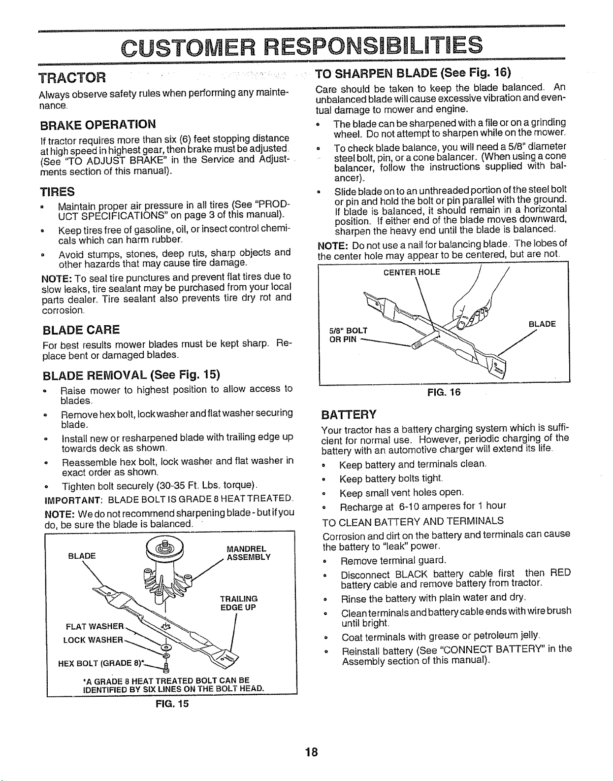
BLADE REMOVAL (See Fig, 15)
o Raise mower to highest position to allow access to
blades
= Remove hex bolt, Iockwasher and flat washer securing
blade.
o Install new or resharpened blade with trailing edge up
towards deck as shown..
o Reassemble hex bolt, lock washer-and flat washer in
exact order as shown,
o Tighten bolt securely (30-35 R. Lbs,. torque).
IMPORTANT: BLADE BOLT IS GRADE 8 HEATTREATED,
NOTE: We do not recommend sharpening blade- but if you
do, be sure the blade is balanced.
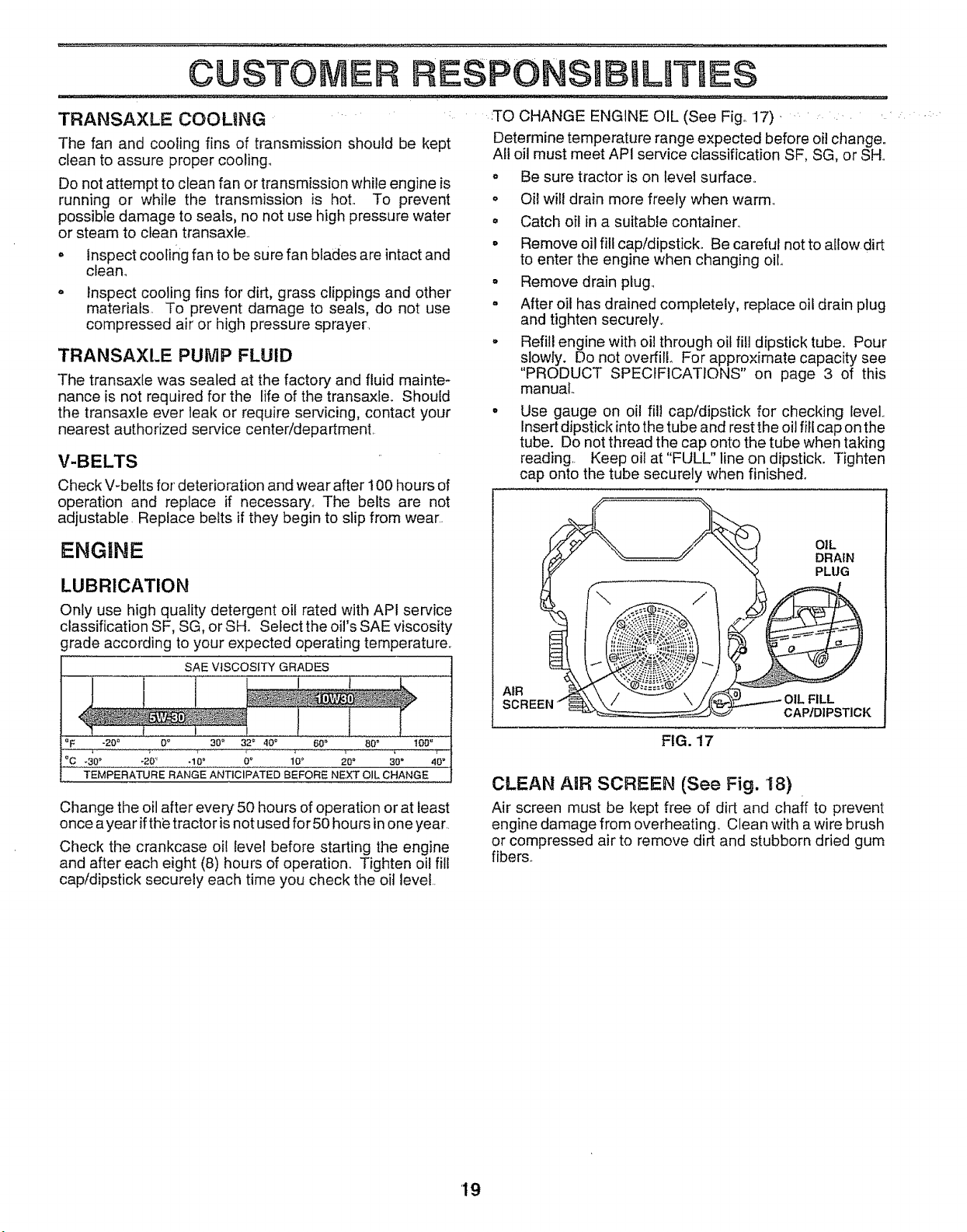
Care should be taken to keep the blade balanced.. An
unbalanced blade will cause excessive vibration and even-
tual damage to mower and engine°
- The blade can be sharpened with a file or on a grinding
wheel. Do not attempt to sharpen while on the mower_
o To check blade balance, you will need a 5/8" diameter
steel bolt, pin, or a cone balancer,, (When using a cone
balancer, follow the instructions supplied with bal-
ancer).
° Slide blade on to an unthreaded portion of the steel bolt
or pin and hold the bolt or' pin parallel with the ground.
If blade is balanced, it should remain in a-horizontal
position. If either end of the blade moves downward,
sharpen the heavy end until the blade is balanced..
NOTE: Do not use a nail for balancing blade, The lobes of
the center hole may appear to be centered, but are note
CENTERHOLE / /
MANDREL
BLADE ASSEMBLY
TRAILING
EDGE UP
LOCK
HEX BOLT
*A GRADE 8 HEAT TREATED BOLT CAN BE
IDENTIFIED BY SIX LINES ON THE BOLT HEAD,
FIG. 16
BATTERY
Your tractor has a battery" charging system which is suffi-
cient for normal use. However, periodic charging of the
battery with an automotive charger' will extend its life_
• Keep battery and terminals clean.
. Keep battery bolts tight.
= Keep small vent holes open,
o Recharge at 6-10 amperes for' 1 hour
TO CLEAN BATTERY AND TERMINALS
Corrosion and dirt on the battery and terminals can cause
the battery to "leak" power.
= Remove terminal guard.
= Disconnect BLACK battery cable first then RED
battery cable and remove battery from tractor_
o Rinse the battery with plain water' and dry,,
° Clean terminals and battery cable ends with wire brush
until bright,
o Coat terminals with grease or' petroleum jelly
° Reinstall battery (See "CONNECT BATTERY" in the
Assembly section of this manual).
FIG. 15
18
ESPONSIB LITIE$
TRANSAXLE COOLING
The fan and cooling fins of transmission should be kept
clean to assure proper cooling.,
Do not attempt to clean fan or transmission white engine is
running or while the transmission is hot.. To prevent
possible damage to seals, no not use high pressure water
or steam to clean transaxle..
. inspect coofir_g fan to be sure fan blades are intact and
clean°
- inspect cooling fins for dirt, grass clippings and other
materials. To prevent damage to seals, do not use
compressed air or high pressure sprayer.
TRANSAXLE PUMP FLUID
The transax{e was sealed at the factory and fluid mainte-
nance is not required for the life of the transaxle. Should
the transaxle ever leak or require servicing, contact your
nearest authorized service center/department.
Check V-belts for deterioration and wear after 100 hours of
operation and replace if necessary., The belts are not
adjustable. Replace belts if they begin to slip from wear
ENGINE
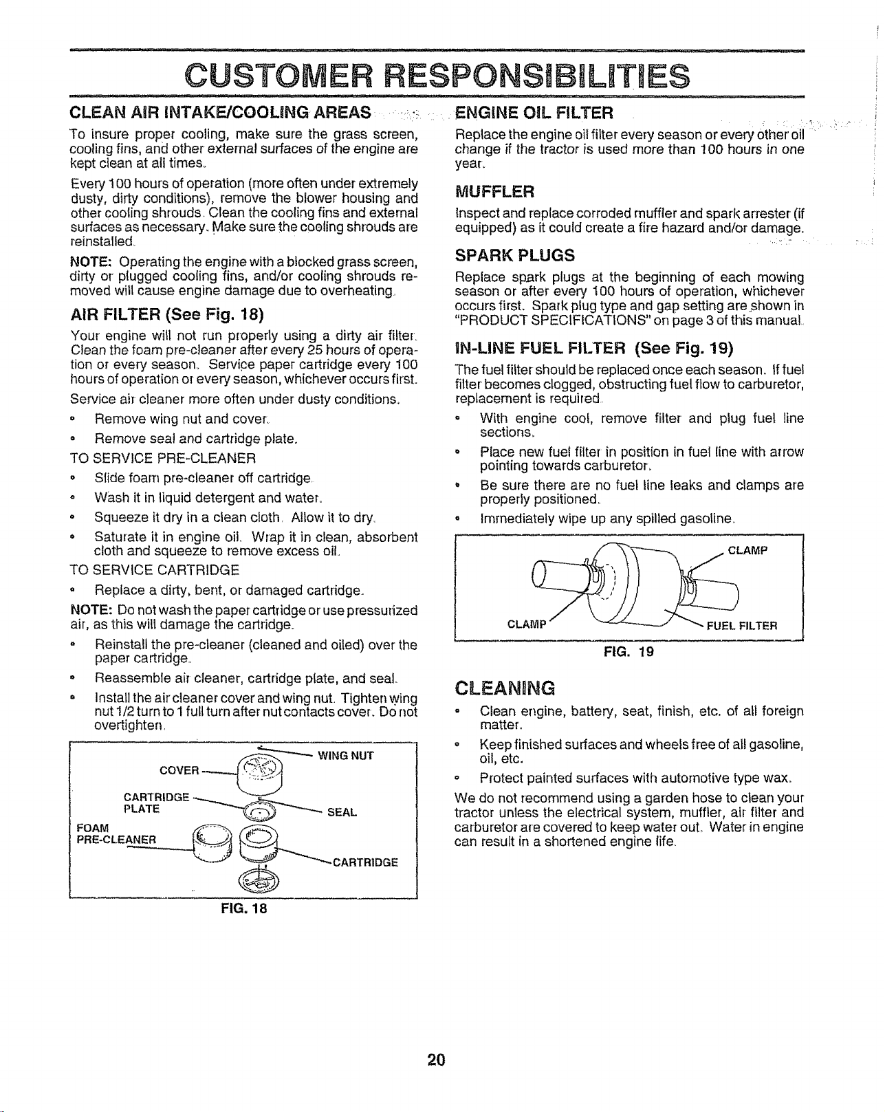
LUBRICATION
Only use high quality detergent oil rated with API service
classification SF, SG, or SHo Select the oil's SAE viscosity
grade according to your expected operating temperature,
SAE VtSCOS{TY GRADES
oF -20 _ 0 o 30 _ 32 _ ,10_ 60 • 80 _ 100 _
°0-30 _....... _20_ ...... -10_............ 0 °........ 107 20° 30" 40"
TEMPERATURE RANGE ANTICIPATED BEFORE NEXT OIL CHANGE
Change the oil after every 50 hours of operation or at least
once a year ifthe tractor is not used for 50 hours in one year
Check the crankcase oil level before starting the engine
and after each eight (8) hours of operation. Tighten oil fill
cap/dipstick securely each time you check the oil level
_TO CHANGE ENGINE OIL (See Fig° 17). '
Determine temperature range expected before oil change.
All oil must meet API service classification SF, SG, or SH.
o Be sure tractor is on level surface,.
o Oil will drain more freely when warm.
• Catch oil in a suitable container_
• Remove oil fill cap/dipstick,, Be careful not to allow dirt
to enter the engine when changing oil
- Remove drain plug.,
- After oil has drained completely, replace oil drain plug
and tighten securely,,
. Refill engine with oil through oil fill dipstick tube. Pour
slowly. Do not overfill For approximate capacity see
"PRODUCT SPECIFICATIONS" on page 3 of this
manual..
Use gauge on oi! fill capfdipstick for checking level.,
Insert dipstick into the tube and rest the oil fill cap on the
tube. Do not thread the cap onto the tube when taking
reading,, Keep oil at "FULU' line on dipstick° Tighten
cap onto the tube securely when finished°
OIL
DRAIN
PLUG
AIR
FIG. 17
CAPtDIPSTICK
CLEAN AIR SCREEN (See Fig. 18)
Air screen must be kept free of dirt and chaff to prevent
engine damage from overheating. Clean with a wire brush
or compressed air to remove dirt and stubborn dried gum
fibers.
19
CUSTOME PC MLITMES
CLEAN AiR INTAKE/COOLING AREAS .... . ENGINE OiL FILTER
To insure proper cooling, make sure the grass screen,
cooling fins, and other external surfaces of the engine are
kept clean at alt times.
Every ! 00 hours of operation (more often under extremely
dusty, dirty conditions), remove the blower housing and
other COOlingshrouds. Clean the cooling fins and external
surfaces as necessary_ Make sure the cooling shrouds are
reinstalledo
NOTE: Operating the engine with a btocked grass screen,
dirty or' plugged cooling fins, and/or cooling shrouds re-
moved wilt cause engine damage due to overheating.
AIR FILTER (See Fig. 18)
Your engine will not run property using a dirty air filter.
Clean the foam pro-cleaner after every 25 hours of opera-
tion or every season. Service paper cartridge every 100
hours of operation or every season, whichever occurs first°
Service air-cleaner more often under dusty conditions.,
o Remove wing nut and cover_
o Remove seal and cartridge plate.
TO SERVICE PRE-CLEANER
• Sfide foam pro-cleaner off cartridge.
o Wash it in liquid detergent and water_
• Squeeze it dry in a clean cloth. Allow it to dry..
o Saturate it in engine oil, Wrap it in clean, absorbent
cloth and squeeze to remove excess oil.
TO SERVICE CARTRIDGE
= Replace a dirty, bent, or damaged cartridge.
NOTE: Do not wash the paper cartridge or use pressurized
air, as this will damage the cartridge.
o Reinstall the pro-cleaner (cleaned and oiled) over the
paper cartridge..
o Reassemble air cleaner, cartridge plate, and seal
= installthe air' cleaner cover and wing nut. Tighten wing
nut 1/2 turn to I full turn after nut contacts cover. Do not
overtighten,
COVER_"-_'--WING NUT
PLATE SEAL
G
Replace the engine oil filter every season or every other' oil '
change if the tractor is used more than 100 hours in one
year_
MUFFLER
Inspect and replace corroded muffler and spark arrestor (if
equipped) as it could create a fire hazard and/or damage_
SPARK PLUGS
Replace spark plugs at the beginning of each mowing
season or after every 100 hours of operation, whichever
occurs first. Spark plug type and gap setting are.,shown in
"PRODUCT SPECIFICATtONS" on page 3 of this manual..
IN-LINE FUEL FILTER (See Fig. 19)
The fuel filter should be replaced once each season, tffuel
filter becomes clogged, obstructing fuel flow to carburetor,
replacement is required.
o With engine coof, remove fiiter and plug fuel line
sections_
Place new fuei filter in position in fuel line with arrow
pointing towards carburetor.
° Be sure there are no fuet line leaks and clamps are
properly positioned.
o Immediately wipe up any spilled gasoline..
CLAMP
CLAMP FUEL FILTER
FIG. 19
CLEANnNG
o Clean engine, batter c, seat, finish, etc. of at_foreign
matter,,
= Keep finished surfaces and wheels free of all gasoline,
oil, etc.
o Protect painted surfaces with automotive type wax_
We do not recommend using a garden hose to clean your
tractor unless the electrical system, muffler, ai=_filter and
carburetor are covered to keep water out1. Water in engine
can result in a shortened engine life,
FIG. 18
2O
SERVICE AND ADJUSTMENTS
..................................... ............................. -- ;-:-,_ :: ......... ___:. ........................................................
CAUTION: BEFORE PERFORMING ANY SERVICE OR ADJUSTMENTS:
o Depress clutch/brake pedal fully and set parking brake,
. Place motion control lever in neutral (N) position.
, Place attachment clutch in "DISENGAGED" position.
° Turn ignition key "OFF" and remove key,
° Make sure the blades and all moving parts have completely stopped.
° Disconnect spark plug wire from spark plug and place wire where it cannot come in contact with
plug ..... . .... -
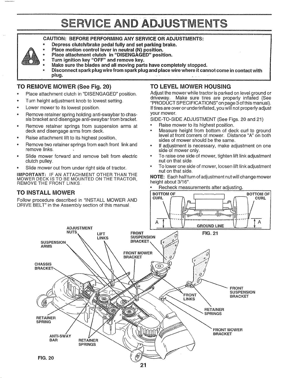
TO REMOVE MOWER (See Fig. 20)
o Place attachment clutch in "DISENGAGED" position,,
o Turn height adjustment knob to lowest setting
° Lower mower to its lowest position,
. Remove retainer spring holding anti-swaybar to chas-
sis bracket and disengage anti-swaybar from bracket.,
° Remove retainer springs from suspension arms at
deck and disengage arms from deck,
- Raise attachment lift to its highest position,.
o Remove two retainer springs from each front link and
remove links,.
• Slide mower forward and remove belt from electric
clutch pulley.,
• Slide mower out from under right side of tractor..
IMPORTANT: IF AN ATTACHMENT OTHER THAN THE
MOWER DECK IS TO BE MOUNTED ON THE TRACTOR,
REMOVE THE FRONT LINKS
TO INSTALL MOWER
Follow procedure described in "INSTALL MOWER AND
DRIVE BELT" in the Assembly section of this manual.
ADJUSTMENT
NUTS LIFT FRONT
SUSPENSION
ARMS
TO LEVEL MOWER HOUSING
Adjust the mower while tractor is parked on level ground or
driveway_ Make sure tires are properly inflated (See
"PRODUCT SPECIFICATIONS" on page 3 of this manual).
If tires are over or underinflated, you will not properly adjust
your mower,,
SIDE-TO-SIDE ADJUSTMENT (See Figs, 20 and 21)
= Raise mower to its highest position,,
° Measure height from bottom of deck curl to ground
level at front corners of mower,, Distance "A" on both
sides of mower should be the same,,
= If adjustment is necessary, make adjustment on one
side of mower only.
° To raise one side of mower, tighten lift link adjustment
nut on that side,
• To lower one side of mower, loosen lift link adjustment
nut on that side.
NOTE: Each half turn of adjustment nut will change mower
height about 3/16",
• Recheck measurements after adjusting.
BOTTOM OF BOTTOM OF
CURL CURL
LIN KS
SUSPENSION
BRACKET
GROUND LINE
FIG, 21
CHASSIS
RETAINER
SPRING
ANTI-SWAY
BAR RETAINER
SPRINGS
LINKS
FRONT
SUSPENSION
BRACKET
RETAINER
SPRINGS
FRONT MOWER
BRACKET
FIG. 20
21
SERVICE AND ADJ
......................... H,, iii ii,,_l i qu
:_ FRONT-TO_BACKADJUSTMENT (See Figs° 22 and 23)
IMPORTANT: DECK MUST BE LEVEL SIDE-TO-SIDE. IF
THE FOLLOWING FRONT-TO-BACK ADJUSTMENT IS
NECESSARY, BE SURE TO ADJUST BOTH FRONT LINKS
EQUALLY SO MOWER WILL STAY LEVEL SIDE-TO-SIDE,
To obtain the best cutting results, the mower housing
should be adjusted so the front is approximately 1/8" to 1/2"
lower than the rear when the mower is in its highest
position_ .....
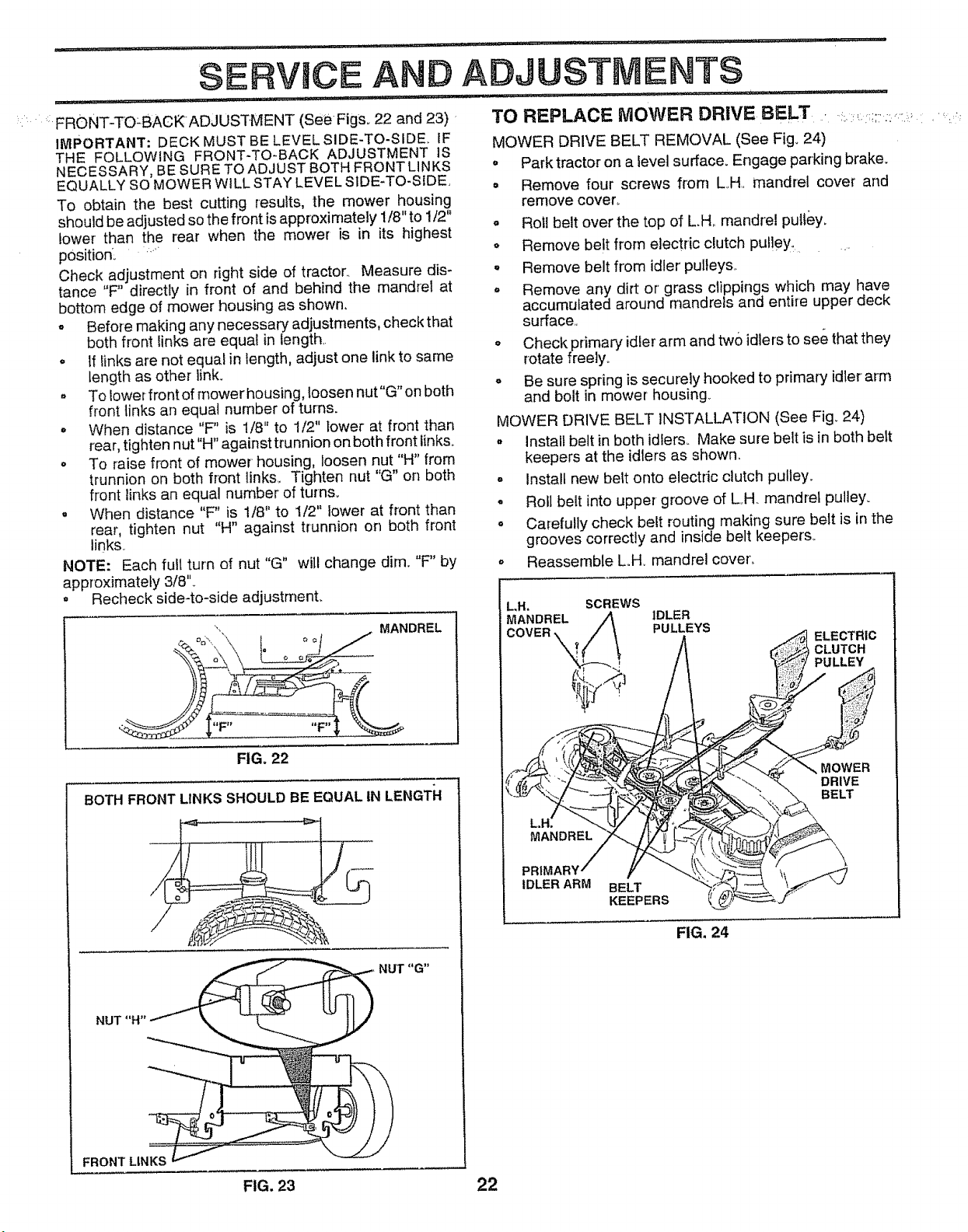
Check adjustment on right side of tractor., Measure dis-
tance "F" directly in front of and behind the mandrel at
bottom edge of mower housing as shown.
o Before making any necessary adjustments, check that
both front links are equal in length,.
o If links are not equal in length, adjust one link to same
length as other link.
. To lower front of mower housing, loosen nut"G" on both
front links an equal number of turns.
- When distance "F" is 1/8" to 1/2" lower at front than
rear, tighten nut"H" against trunnion on both front links°
o To raise front of mower housing, loosen nut "H" from
trunnion on both front links_ Tighten nut "G" on both
front links an equal number of turns°
• When distance "F' is 1/8" to 1/2" lower at front than
rear, tighten nut "H" against trunnion on both front
links,.
NOTE: Each fult turn of nut "G" will change dim. "F" by
approximately 3/8'L
o Recheck side-to-side adjustment.
MANDREL
llFJ_
FIG. 22
BOTH FRONT LINKS SHOULD BE EQUAL IN LENGTFI
NUT "G"
FRONT LINKS
.... ,ll,i, i, , i,ilUlll
STMENTS
TO REPLACE MOWER DRIVE BELT .
MOWER DRIVE BELT REMOVAL (See Fig. 24)
• Park tractor on a level surface. Engage parking brake.
• Remove four screws from L,,H,, mandrel cover and
remove cover,.
o Roll belt over the top of LH, mandrel pull&y.
o Remove belt from electric clutch pul!ey,_.......
- Remove belt from idler' pulleys,.
° Remove any dirt or grass clippings which may have
accumulated around mandrels and entire upper deck
surface,,
o Check primary idler arm and two idlers to see that they
rotate freely°
° Be sure spring is securely hooked to primary idler arm
and bolt in mower housing.
MOWER DRIVE BELT INSTALLATION (See Fig. 24)
. Install belt in both idlers. Make sure belt is in both belt
keepers at the idlers as shown.
- Install new belt onto electric clutch pulley.
- Roll belt into upper groove of L.H mandrel pulley.
o Carefully check belt routing making sure belt is in the
grooves correctly and inside belt keepers.
° Reassemble L,.H. mandrel cover',,
LH. SCREWS
MANDREL IDLER
PULLEYS
ELECTRIC
CLUTCH
PULLEY
MOWER
DRIVE
BELT
IDLER ARM BELT
KEEPERS
FIG. 24
FIG. 23 22
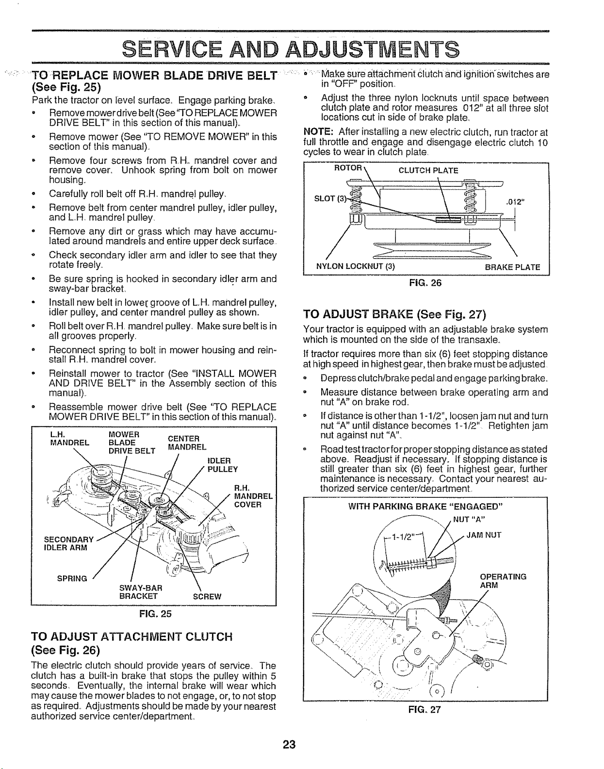
rl,,:_iL i:,:lJ .............
SERVICE A D ADJUSTMENTS
"_'_; 'TO:REPLACE MOWER BLADE DRIVE BELT" ; Make sure attaclimedt ctutch and igniti0n'switches are
(See Fig. 25) in "OFF" position,
Park the tractor on level surlace.. Engage parking brake,
• Remove mower drive belt (See'q'O REPLACE MOWER
DRIVE BELT" in this section of this manual)..
o Remove mower (See "TO REMOVE MOWER" in this
section of this manual)..
• Remove four screws from R.H., mandrel cover and
remove cover, Unhook spring from bolt on mower
housing..
° Carefully roll belt off R.H_ mandrel pulley.
" Remove belt from center mandrel pulley, idler pulley,
and LH. mandrel pulley
• Remove any dirt or grass which may have accumu-
lated around mandrels and entire upper deck surface
o Check secondary idler' arm and idler to see that they
rotate freely.
• Be sure spring is hooked in secondary idler arm and
sway-bar brackeL
° Install new belt in lowel_ groove of L.H.. mandrel pulley,
idler pulley, and center mandrel pulley as shown.
° Roll belt over R.H, mandrel pulley Make sure belt is in
al! grooves properly.
• Reconnect spring to bolt in mower housing and rein-
stall RH.. mandrel cover_
o Reinstall mower to tractor (See "INSTALL MOWER
AND DRIVE BELT" in the Assembly section of this
manual)..
° Reassemble mower drive belt (See "TO REPLACE
MOWER DRIVE BELT" in this section of this manual)°
LH. MOWER CENTER
MANDREL BLADE
DRIVE BELT MANDREL
IDLER
PULLEY
R_H_
MANDREL
'. COVER
SECONDAt
IDLER ARM
SPRING
SWAY-BAR
BRACKET SCREW
FIG, 25
TO ADJUST ATTACHMENT CLUTCH
(See Fig. 26)
The electric clutch should provide years of service. The
clutch has a built-in brake that stops the pulley within 5
seconds. Eventually, the internal brake will wear which
may cause the mower blades to not engage, or, to not stop
as required.. Adjustments should be made by your nearest
authorized service centeddepartmenL
o Adjust the three nylon locknuts until space between
clutch plate and rotor measures 012" at al! three slot
locations cut in side of brake plate_
NOTE: After installing a new electric clutch, run tractor at
full throttle and engage and disengage electric clutch 10
cycles to wear in clutch plate.
ROTOR
CLUTCH PLATE
SLOT
NYLON LOCI(NUT (3)
FiG. 26
BRAKE PLATE
TO ADJUST BRAKE (See Fig, 27)
Your tractor is equipped with an adjustable brake system
which is mounted on the side of the transaxle,
if tractor requires more than six (6) feet stopping distance
at high speed in highest gear, then brake must be adjusted
• Depress clutch/brake pedal and en gage parking brake_.
• Measure distance between brake operating arm and
nut "A" on brake rod..
If distance is other than 1-1/2", loosen jam nut and turn
nut "A" until distance becomes 1-1/2" Retighten jam
nut against nut "A"..
Road test tractor for proper stopping distance as stated
above. Readjust if necessary, tf stopping distance is
still greater than six (6) feet in highest gear, further
maintenance is necessary., Contact your nearest au-
thorized service center/department.
WITH PARKING BRAKE "ENGAGED"
FIG, 27
23
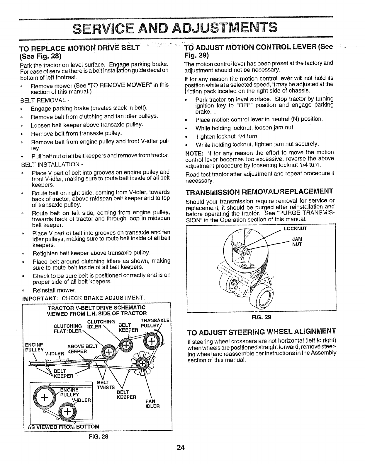
RVJCE AND ADJUSTM NT$
TO REPLACEMOTION0RIVECELT ' ADJUSTMOTIONCONTROLLEVER(See
(See Fig. 28)
Park the tractor on level surface_ Engage parking brake.
For ease of service there is a belt installation guide decal on
bottom of left footrest.
o Remove mower (See "TO REMOVE MOWER" in this
section of this manual.)
BELT REMOVAL -
o Engage parking brake (creates slack in belt)o
o Remove belt from clutching and fan idler' pulleys..
• Loosen belt keeper' above transaxle pulley.
° Remove belt flom transaxle pulley..
= Remove belt from engine pulley and front V-idler pul-
]ey
° Pull belt out of all belt keepers and remove from tractor.
BELT INSTALLATION -
° Place V part of belt into grooves on engine pulley and
front V-idler, making sure to route belt inside of all belt
keepers_
o Route belt on right side, coming from V-idler, towards
back of tractor, above midspan belt keeper and to top
of.transaxle pulley.
° Route belt on left side, coming from engine pulle_),
towards back of tractor and through loop in midspan
belt keeper..
o Place V part of belt into grooves on transaxle and fan
idler pulleys, making sure to route belt inside of all belt
keepers,.
• Retighten belt keeper above transaxle pulley.
• Place belt around clutching idlers as shown, making
sure to route belt inside of all belt keepers°
° Check to be sure belt is positioned correctly and is on
proper side of all belt keepers.
o Reinstall mower.
IMPORTANT; CHECK BRAKE ADJUSTMENT
TRACTOR V-BELT DRIVE SCHEMATIC
VIEWED FROM LH. SIDE OF TRACTOR
CLUTCHING TRANSAXLE
CLUTCHING IDLER BELT PUI
ENGINE ABOVE
PULLEY
t BELTTWISTS
BELT
KEEPER
FAN
IDLER
AS VIEWED FROM BOTTOM
Fig. 29)
The motion control lever has been preset at the factory and
adjustment should not be necessary,.
If for any reason the motion control lever will not hold its
positionwhile at a selected speed, it may be adjusted at the
friction pack located on the right side of chassis.
= Park tractor on level surface. Stop tractor by turning
ignition key to "OFF" position and engage parking
brake.
• Place motion control lever' in neutral (N) position..
° While holding Iocknut, loosen jam nut
= Tighten Iocknut 1/4 turn.
° While holding locknut, tighten jam nut securely.
NOTE: If for any reason the effort to move the motion
control lever becomes too excessive, reverse the above
adjustment procedure by loosening locknut t/4 turn..
Road test tractor after adjustment and repeat procedure if
necessary.,
TRANSMISSION REMOVAL/REPLACElVlENT
Should your transmission require removal for service or
replacement, it should be purged after reinstallation and
before operating the tractor. See "PURGE TRANSMIS-
SION" in the Operation section of this manual
LOCKNUT
JAM
NUT
FIG, 29
TO ADJUST STEERING WHEEL ALIGNMENT
if steering wheel crossbars are not horizontal (left to right)
when wheels are positioned straight forward, remove steer-
ing wheel and reassemble per instructions in the Assembly
section of this manual_
FIG. 28
24
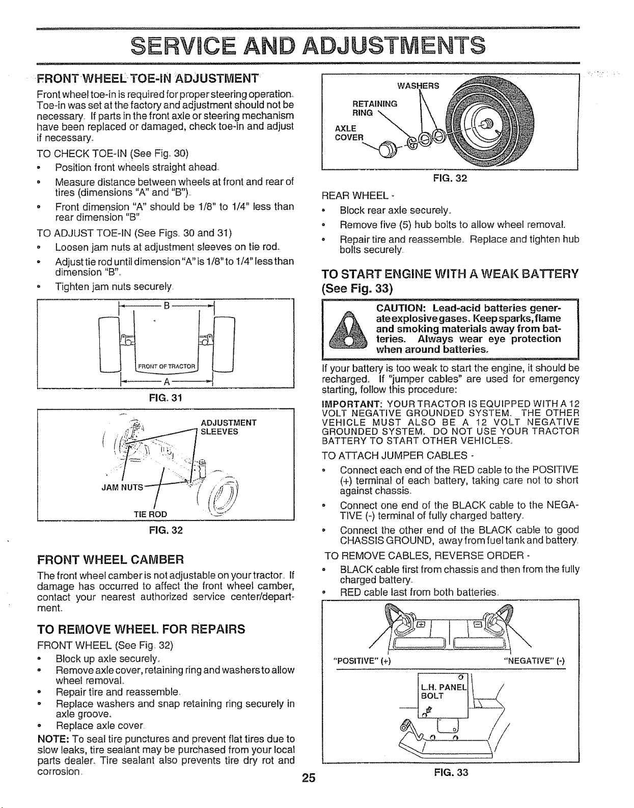
SERVBCE AND ADjUS VIENTS
-FRONTWHEEI. -TOE,IN ADJUSTMENT
Front wheel toe-in is required for proper steering operation°
Toe-in was set at the factory and adjustment should not be
necessary. If parts in the front axle or steering mechanism
have been replaced or damaged, check toe-in and adjust
if necessary_
TO CHECK TOE-IN (See Fig. 30)
o Position front wheels straight ahead..
o Measu re distance between wheels at front and rear of
tires (dimensions "A" and "B").
. Front dimension "A" should be 1/8" to 1/4" less than
rear dimen.sion "B"
TO ADJUST TOE-IN (See Figs.. 30 and 31)
o Loosen jam nuts at adjustment sleeves on tie rod.
* Adjust tie rod until dimension "A" is 1/8" to t/4" less than
dimension "B"o
° Tighten jam nuts securely.
_------- A ------_
FIGo 31
(
ADJUSTMENT
SLEEVES
JAM
TIE ROD
FIG. 32
FRONT WHEEL CAMBER
The front wheel camber is not adjustable on your tractor.. If
damage has occurred to affect the front wheel camber,
contact your nearest authorized service center/depart-
ment..
TO REMOVE WHEEL FOR REPAIRS
FRONT WHEEL (See Fig 32)
• Block up axle securely..
° Remove axlecover, retaining ring and washersto altow
wheel removal.
° Repair tire and reassemble.
° Replace washers and snap retaining ring securely in
axle groover
• Replace axle cover
NOTE: To seal tire punctures and prevent flat tires due to
stow leaks, tire sealant may be purchased from your local
parts dealer. Tire sealant also prevents tire dry rot and
corrosion.
25
RETAINING
RING
AXLE
COVER
_,
FIG. 32
REAR WHEEL _
• Block rear axle securely..
° Remove five (5) hub bolts to allow wheel removal.
° Repair tire and reassemble.. Replace and tighten hub
bolts securely.
TO START ENGINE WITH A WEAK BATTERY
(See Fig. 33)
! . CAUTION: Lead:acid bafferies gener,
=} ate explosive gases. Keep sparks, flame
! t i, _ and smoking materials away from bat-
_ ii _ teries. Always wear eye protection
when around batteries.
if your battery is too weak to start the engine, it should be
recharged,, If "jumper cables" are used for emergency
starting, follow this procedure:
IMPORTANT: YOUR TRACTOR IS EQUIPPED WITH A 12
VOLT NEGATIVE GROUNDED SYSTEM.. THE OTHER
VEHICLE MUST ALSO BE A t2 VOLT NEGATIVE
GROUNDED SYSTEM. DO NOT USE YOUR TRACTOR
BATTERY TO START OTHER VEHICLES..
TO ATTACH JUMPER CABLES -
• Connect each end of the RED cable to the POSITIVE
(+) terminal of each battery, taking care not to short
against chassis..
• Connect one end of the BLACK cable to the NEGA-
TIVE (_)terminal of fully charged battery..
° Connect the other end of the BLACK cable to good
CHASSIS GROUND, away from fuel tank and battery
TO REMOVE CABLES, REVERSE ORDER -
° BLACK cable first from chassis and then from the fully
charged battery..
RED cable last from both batteries.
"POSITIVE" (+) "NEGATIVE" {-)
FIG. 33
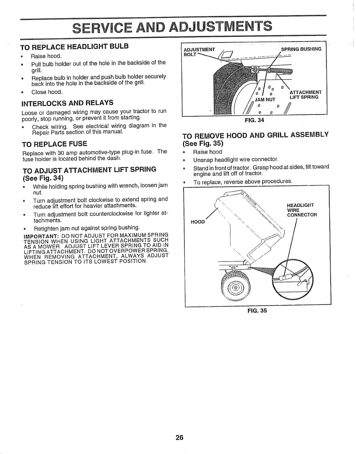
SERVmCE AND ADJUSTMENTS
TO REPLACE HEADLIGHT BULB
= Raise hood°
• Pull bulb holder out of the hole in the backside of the
grill..
o Replace bulb in holder' and push bulb holder securely
back into the hole in the backside of the gfillo
= Close hood.
INTERLOCKS AND RELAYS
Loose or damaged wiring may cause your tractor to run
poorly, stop running, or prevent it from starting.
° Check wiring. See electrical wiring diagram in the
Repair Parts section of this manual
TO REPLACE FUSE
Replace with 30 amp automotive-type plugqn fuse. The
fuse holder is located behind the dash.
TO ADJUST ATTACHMENT LIFT SPRING
(See Fig. 34)
o White holding spring bushing with wrench, toosen jam
nut.
= Turn adjustment bolt clockwise to extend spring and
reduce lift effort for heavier' attachments.
° Turn adjustment bolt counterclockwise for lighter at-
tachments.
. Retighten jam nut against spring bushing,.
IMPORTANT: DO NOTADJUST FOR MAXIMUM SPRING
TENSION WHEN USING LIGHT ATTACHMENTS SUCH
AS A MOWER.. ADJUST LIFT LEVER SPRING TO -AID tN
LIFTING ATTACHMENT. DO NOTOVERPOWER SPRING,
WHEN REMOVING ATTACHMENT, ALWAYS ADJUST
SPRING TENS{ON TO ITS LOWEST POSITION.
ADJUSTMENT
SPRING BUSHING
e ATTACHMENT
JAM NUT LIFT SPRING
_ o
FIG. 34
TO REMOVE HOOD AND GRILL ASSEMBLY
(See Fig. 35)
° Raise hood
- Unsnap headlight wire connector.
- Stand in front of tractor.. Grasp hood at sides, tilt toward
engine and lift off of tractor°
• To replace, reverse above procedures.
FIG. 35
26
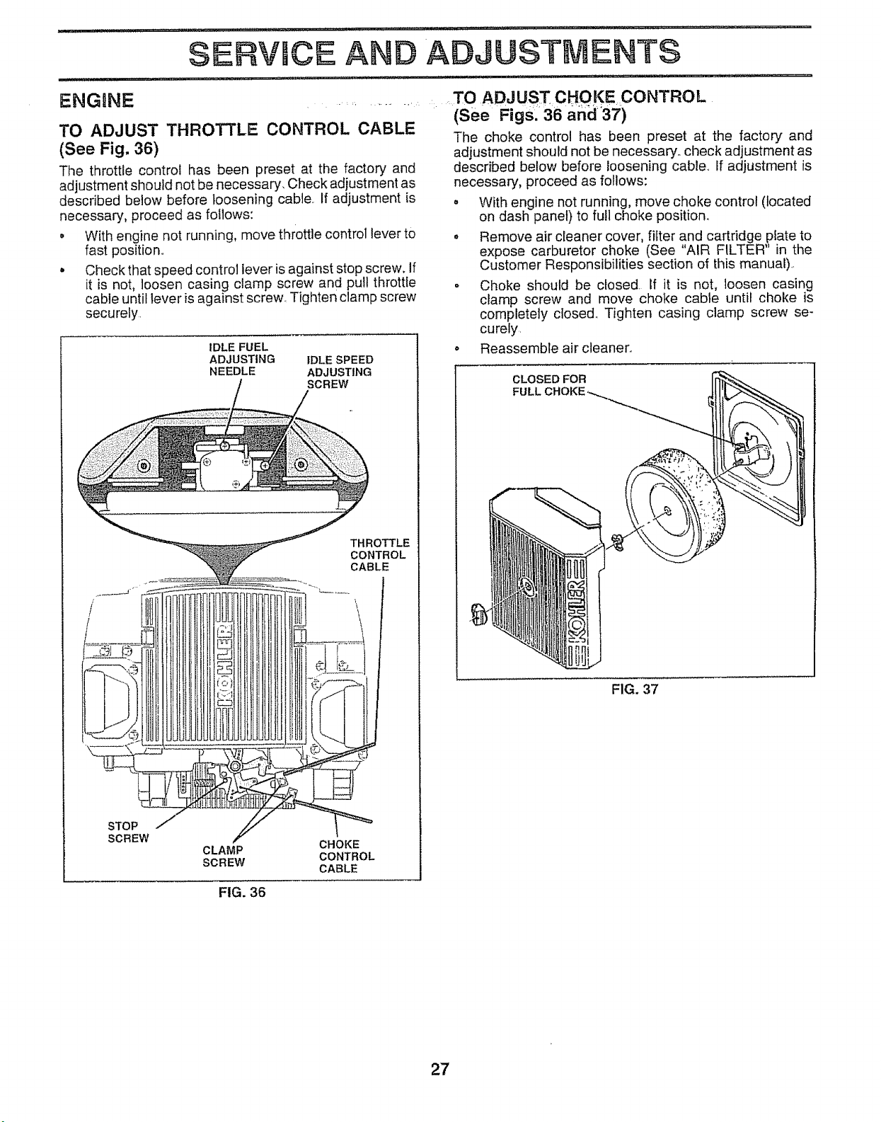
SERVICE A
ADJUSTMENTS
ENGENE
TO ADJUST THROTTLE CONTROL CABLE
(See Fig, 36)
T!le throttle control has been preset at the factory and
adjustment should not be necessary_ Check adjustment as
described below before loosening cable. If adjustment is
necessary, proceed as follows:
o With engine not running, move throttle control lever to
fast position,,
• Check that speed control lever is against stop screw. If
it is not, loosen casing clamp screw and pull throttle
cable until lever is against screw Tighten clamp screw
securely,
IDLE FUEL
ADJUSTING
NEEDLE
....TO ADJUST CHOKE CONTROL
............ _i (See Figs,"36 arid37)
/
THROTTLE
CONTROL
CABLE
STOP
SCREW
CLAMP
SCREW
IDLE SPEED
ADJUSTING
SCREW
The choke control has been preset at the factory and
adjustment should not be necessary,, check adjustment as
described below before loosening cable,, If adjustment is
necessary, proceed as follows:
o With engine not running, move choke control (located
on dash panel) to full choke position°
o Remove air cleaner cover, filter and cartridge plate to
expose carburetor choke (See "AIR FILTER" in the
Customer Responsibilities section of this manual),.
• Choke should be closed If it is not, loosen casing
clamp screw and move choke cable until choke is
completely closed,, Tighten casing clamp screw se-
curely.
o Reassemble air cleaner.
CHOKE
CONTROL
CABLE
CLOSED FOR
FULL CHOKE
FIG. 37
FIG. 36
27
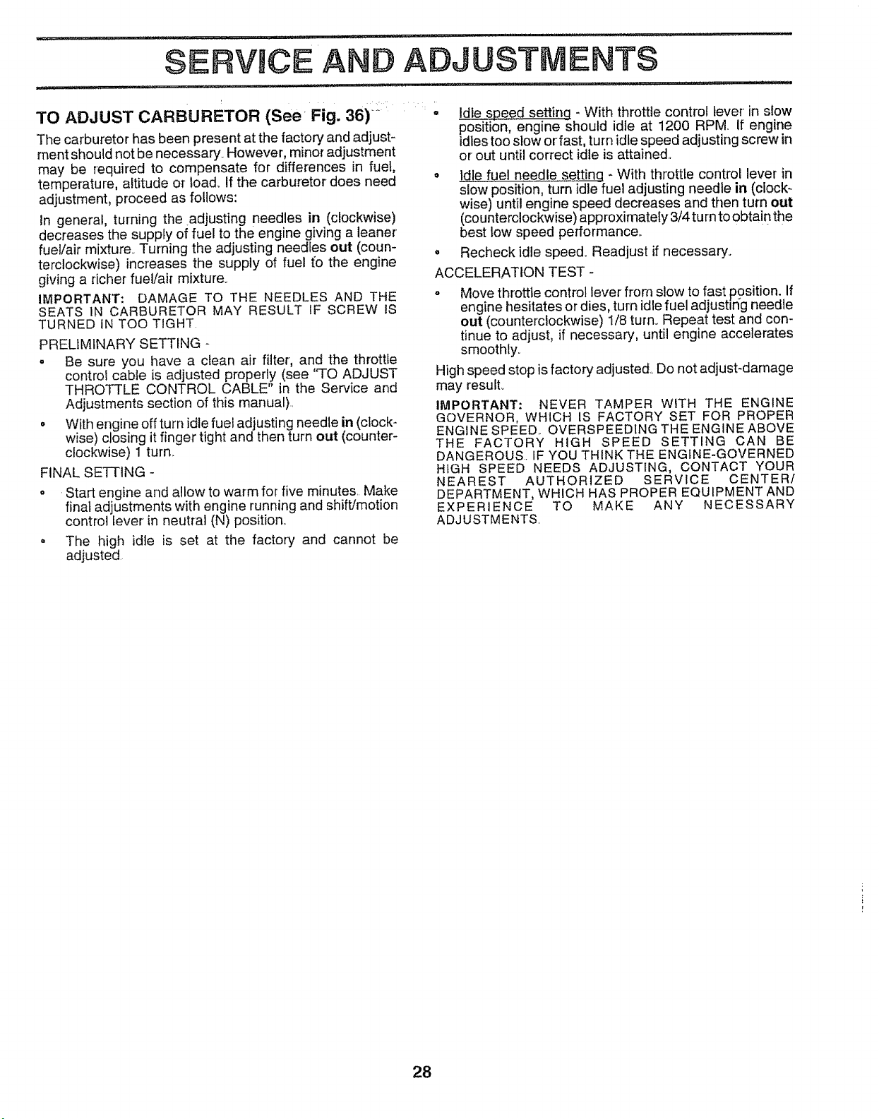
.................... ii :1,1 i null ' ii iiii
SERVmCE A D ADJUSTMENTS
TO ADJUST CARBURETOR (See Fig. 36) ....
The carburetor has been present at the factory and adjust-
ment should not be necessary_ However, minor adjustment
may be required to compensate for differences in fuel,
temperature, altitude or load. If the carburetor does need
adjustment, proceed as follows:
in general, turning the adjusting needles in (clockwise)
decreases the supply of fuel to the engine giving a leaner
fuel!air mixture, Turning the adjusting needles out (coun-
terclockwise) increases the supply of fuel t'o the engine
giving a richer fuel/air mixture_
IMPORTANT: DAMAGE TO THE NEEDLES AND THE
SEATS 1N CARBURETOR MAY RESULT IF SCREW IS
TURNED iN TOO TIGHT.
PRELIMINARY SETTING
= Be sure you have a clean air filter, and the throttle
control cable is adjusted properly (see 'q-O ADJUST
THROTTLE CONTROL CABLE" in the Sewice and
Adjustments section of this manual)..
• With engine off turn idle fuel adjusting needle in (clock-
wise) closing it finger tight and then turn out (counter-
clockwise) 1 turn.
FINAL SETTING -
o Start engine and allow to warm for five minutes Make
final adjustments with engine running and shift/motion
control lever in neutral (N) position,,
o The high idle is set at the factory and cannot be
adjusted.
• Idle speed setting - With throttle control lever in slow
p6s'iti'o'n; engine should idle at 1200 RPM If engine
idles too stow or fast, turn idle speed adjusting screw in
or out until correct idle is attained..
o Idle fuel needle settincl - With throttle control lever in
slow position, turn idle fuel adjusting needle in (clock-
wise) until engine speed decreases and then turn out
(counterclockwise) approximately 3/4 turn to obtai nthe
best low speed performance°
= Recheck idle speed. Readjust if necessary_
ACCELERATION TEST -
o Move throttle control lever from slow to fast position. If
engine hesitates or dies, turn idle fuel adjustlrig needle
out (counterclockwise) 1/8 turn., Repeat test and con-
tinue to adjust, if necessary, until engine accelerates
smoothly_
High speed stop is factory adjusted.. Do not adjust-damage
may result.
IMPORTANT: NEVER TAMPER WITH THE ENGINE
GOVERNOR, WHICH IS FACTORY SET FOR PROPER
ENGINE SPEED.. OVERSPEED1NG THE ENGINE ABOVE
THE FACTORY HIGH SPEED SETTING CAN BE
DANGEROUS. IF YOU THINK THE ENGINE-GOVERNED
HIGH SPEED NEEDS ADJUSTING, CONTACT YOUR
NEAREST AUTHORIZED SERVICE CENTER/
DEPARTMENT, WHICH HAS PROPER EQUIPMENT AND
EXPERIENCE TO MAKE ANY NECESSARY
ADJUSTMENTS.
28
STORAGE
immediately prepare your tractor for storage at the end of
the season or if the tractor will not be used for 30 days or
more,
CAUTION: Never store the tractor with
gasoline in the tank inside a building
where fumes may reach an open flame
or spark. Allow the engine to cool
before storing in any enclosure,
TRACTOR
Remove mower from tractor for winter storage. When
mower is to be stored for a period of time, clean it thor-
oughly, remove all dirt, grease, leaves, etc., Store in a
clean, dry area.
• Clean entire tractor (See "CLEANING" in the Customer
Responsibilities section of this manual),
o Inspect and replace belts, if necessary (See belt re-
placement instructions in the Service and Adjustments
section of this manual),,
° Lubricate as shown in'the Customer Responsibilities
section of this manual,
o Be sure that all nuts, bolts and screws are securely
fastened Inspect moving parts for damage, breakage
and wear,, Replace if necessary.,
• Touch up all rusted or chipped paint surfaces; sand
lightly before painting.,
BATTERY
• Fully charge the battery for storage,,
, After a period of time in storage, battery may require
recharging,
° To help prevent corrosion and power leakage during
long periods of storage, battery cables should be
disconnected and battery cleaned thoroughly (see 'TO
CLEAN BATTERY AND TERMINALS" in the Cus-
tomer Responsibilities section of this manual),
° After cleaning, leave cables disconnected and place
cables where they cannot come in contact with battery
terminals,
°
°
Be sure battery' drain tube is securely attached,
tf battery is removed from tractor for storage, do not
store battery directly on concrete or damp surfaces,
ENGINE
FUEL SYSTEM
IMPORTANT: IT IS IMPORTANT TO PREVENT GUM
DEPOSITS FROM FORMING IN ESSENTIAL FUEL
SYSTEM PARTS SUCH AS CARBURETOR, FUEL FILTER,
FUEL HOSE, OR TANK DURING STORAGE. ALSO,
EXPERIENCE INDICATES THAT ALCOHOL BLENDED
FUELS (CALLED GASOHOL OR USING ETHANOL OR
METHANOL) CAN ATTRACT MOISTURE WHICH LEADS
TO SEPARATION AND FORMATION OF ACIDS DURING
STORAGE. ACIDIC GAS CAN DAMAGE THE FUEL
SYSTEM OF AN ENGINE WHILE IN STORAGE..
° Drain the fuel tank,,
o Start the engine and let it run until the fuel lines and
carburetor are empty_
o Never use engine or carburetor cleaner products in the
fuel tank or permanent damage may occur..
• Use fresh fuel next season,,
NOTE: Fuel stabilizer is an acceptable alternative in
minimizing the formation of fuel gum deposits during stor-
age,. Add stabilizer to gasoline in fuel tank or storage
container,, Always follow the mix ratio found on stabilizer
containen Run engine at least 10 minutes after adding
stabilizer to allow the stabilizer to reach the carburetor. Do
not drain the gas tank and carburetor if using fuel stabilizero
ENGnNE OIL
Drain oil (with engine warm) and replace with clean engine
oil,, (See "ENGINE" in the Customer Responsibilities
section of this manual),
CYLINDERS
o Remove spark plug(s),
° Pour one ounce of oil through spark plug hole(s) into
cylinder(s).
° Turn ignition key to"START" position for afew seconds
to distribute oil
, Replace with new spark plug(s),
OTHER
, Do not store gasoline from one season to another,
° Replace your gasoline can if your can starts to rust,,
Rust and/or dirt in your gasoline will cause problems.,
o If possible, store your tractor indoors and cover it to
give protection from dust and dirt,
° Cover your tractor with a suitable protective cover that
does not retain moisture, Do not use plastic. Plastic
cannot breathe which allows condensation to form and
will cause your tractor to rust,,
IMPORTANT: NEVER COVER TRACTOR WHILE ENGINE
AND EXHAUST AREAS ARE STILL WARM,
29

ii_l,ill
Will not start
TROU
CAUSE
1,. Out of fuel
LESHOOTING POINTS
CORRECTION
1_ Fil! fuel lank
Hard to start
Engine will not turn over
Engine clicks but will not
start
Loss of power
Excessive vibration
2, Engine not "CHOKED" properly,
3. Engine flooded
4.. Bad sparkplug
5, Dirty air filler..
6. Dirty fuel filter,
7 Water in rue!
8 Loose or damaged wiring
9, Carburetor out of adjustment
t0. Engine valves out of adjustment..
1 Dirty air fiiter.
2 Bad spark plug
3, Weak or dead battery.
4. Dirty fuel filter.
5, Stale or dirtyfuei
6, Loose or damaged wiring.
7. Carburetor out of adiustment
8 Engine valves out of adjustment.
1. Ctutch_rake pedalnot depressed
2 Attachment clutch is engaged,,
3 Weak or dead battery
4. Blown fuse
5 Corroded battery terminals
6 Loose or damaged wiring
7 Fautty ignition switch,
8 Faulty solenoid or starter
9 Faulty operator presence switch(es)
1 Weak or dead battery,,
2. Corroded battery terminals
3, Loose or damaged wiring
4. Faulty solenoid or starter
1,, Cutting too much grass/too fast
2 Throttle in "CHOKE" position.
3 Build*up of grass, leaves and trash under mower,
4 Dirty air filter,
5 Low oit level/dirty oil
6 Faufty spark plug
7 Dirty fuel filter.
8 Stale or dirty fuel
9 Water in fuet
10, Spark plug wire !case
11 Dirty engine air screen/_s
t2 Dirty/clogged muffler,
t3 Loose or damaged wiring.
14 Carburetor out of adjustment.
15 Engine vatves out of adjustment
..... illl: i l lll ...............................
1 Worn, bent or loose blade
2, Bent blade mandrel
3 Loose/damaged part(s)
2. See ='TO START ENGINE" in Operation section.
3 Wait several minutes before attempting to start,
4, Repiace spark plug.
5,. Clear_Jreptace air filter,
6,, Replace fuel filter,
7,. Drain fuel tank and carburetor, refill tank with fresh
gasotine and replace fuel filter
8. Check alI wiring.
9.. See "To Adjust Carburetor" in Service Adjustments
section,
10, Contact an authorized service center/department
1 Clean!replace air tilter
2 Replace spark plug.
3 Recharge or replace battery
4,, Replace fuet filter.
5. Drain fuei tank and refill with fresh gasoline
6, Check alt wiring.
7 See "To Adjust Carburetor" in Service Adjustments
section_
8 Contact an authorized service center/department
1. Depress clutchforake pedal
2 Disengage attachment clutch,
3 Recharge or replace battery
4 Replace fuse
5 Clean battery terminals
6, Check all wiring
7, Check/replace ignition switch
8. Check/replace solenoid or starter
9. Contact an authorized service center/department.
t Recharge or replace battery,
2 Ciean battery terminals
3. Check all wiring
4,. Checld_ep[ace solenoid or starter
1 Set in "Higher Cut" position/reduce speed
2 Adjust throttle control
3. Clean underside of mower housing,
4, Clean/replace air filter
5.. Check oil level/change oil
6 Clean and regap or change spark plug,
7, Replace fuel filter,
8 Drain fuel tank and refill with fresh gasoline,
9 Drain fuel tank and carburetor, retilJ tank with fresh
gasoline and replace fuel filter
t0 Connect and tighten spark plug wire
t 1 Clean engine air screen/fins.
12 Clean/replace muffler
13. Check all widng.
14, See 'qo Adjust Carburetor" in Service Adjustments
section.
t5 Contact an authorized service center/department
1.. Replace blade Tighten blade bott,,
2. Replace blade mandrel.
3 Tighten loose part(s) Replace damaged parts
3O

TROU LESHOOTmNG POtNTS
PROBLEM
Engine continues to run
when operator leaves seat
with attachment clutch
engaged
Poor cut - uneven
Mower blades will not
rotate
Poor grass discharge
Headlight(s) not working
(if so equipped)
Battery will not charge
Loss of drive
Engine "backfires"
when turning engine
"OFF"
CAUSE
1 Faulty operator-safety presence control system
1 Worn, bent or loose blade
2. Mower deck not level. . . ; •
3 Buildup of grass, leaves, and trash under mower
4 Bent blade mandrel
5 Clogged mower deck vent holes from buildup of
grass, leaves, and trash around mandrels
1. Obstruction in clutch mechanism
2. Worn/damaged mower drive belt
3 Frozen idler pulley
4 Frozen blade mandrel.
1 Engine speed too slov,;.
2 Travel speed too test
3 Wet grass.
4 Mower deck not level
5 Low/uneven tire air pressure
6. Worn, bent or loose blade
7 Buildup of grass, leaves and trash under mower
8 Mower drive belt worn.
9 Blades improperly installed
10 Improper blades used
t 1 Clogged mower deck vent holes from buildup of
grass, leaves, and trash around mandrels.
I. Switch is "OFF"
2 Bulb(s) burned out
3 Faulty light switch.
4 Loose or damaged wiring
5 Blown fuse
t.. Bad battery celt(s)..
2. Poor cable connections
3 Faulty regulator (if so equipped)
4 Faulty alternator
Engine throttle control not set at "SLOW"
position for 30 seconds before stopping engine
1 Freewheel control in "disengaged" position
2 Motion drive belt worn, damaged, or broken
3 Air trapped in transmission during shipment
or servicing
t
CORRECTION
Check wiring, switches and connections. If not
corrected, contacl an authorized service center/
departmenL
t. Replace b_ade Tighten blade bo_t
2. Level mower deck..
3. Clean underside of mower housing
4 Replace blade mandrel
5 Clean around mandrels to open vent holes
t.. Remove obstruction.
2 Replace mower ddve belt
3 Replace idler pulley..
4 Replace blade mandrel.
1_ Place throttle control in "FAST" position
2. Shift to slower speed
3. Allow grass to dry before mowing
4.. Level mower deck..
5. Check tires for proper air pressure.
& Replace/sharpen blade.. Tighten blade bolt
7. Clean underside of mower housing
8. Replace mower drive belt
9 Reinstal! blades sharp edge down..
!0. Replace wi_l_ blades listed in this manual
1t. Clean around mandrels to open vent holes
1.. Turn switch "ON"
2. Replace bulb(s)
3 Check/replace light switch.
4. Check wiring and connections
5. Replace fuse
t Replace battery
2 Check/clean all connections.
3 Replace regulalor
4 Replace alternator
1.. Place freewheel control in "engaged" position
2.. Replace motion drive belt
3. Purge transmission
t. Move throttle control to "SLOW" position and allow
to id[e for 30 seconds before stopping engine
31

SERVICE NOTES
32
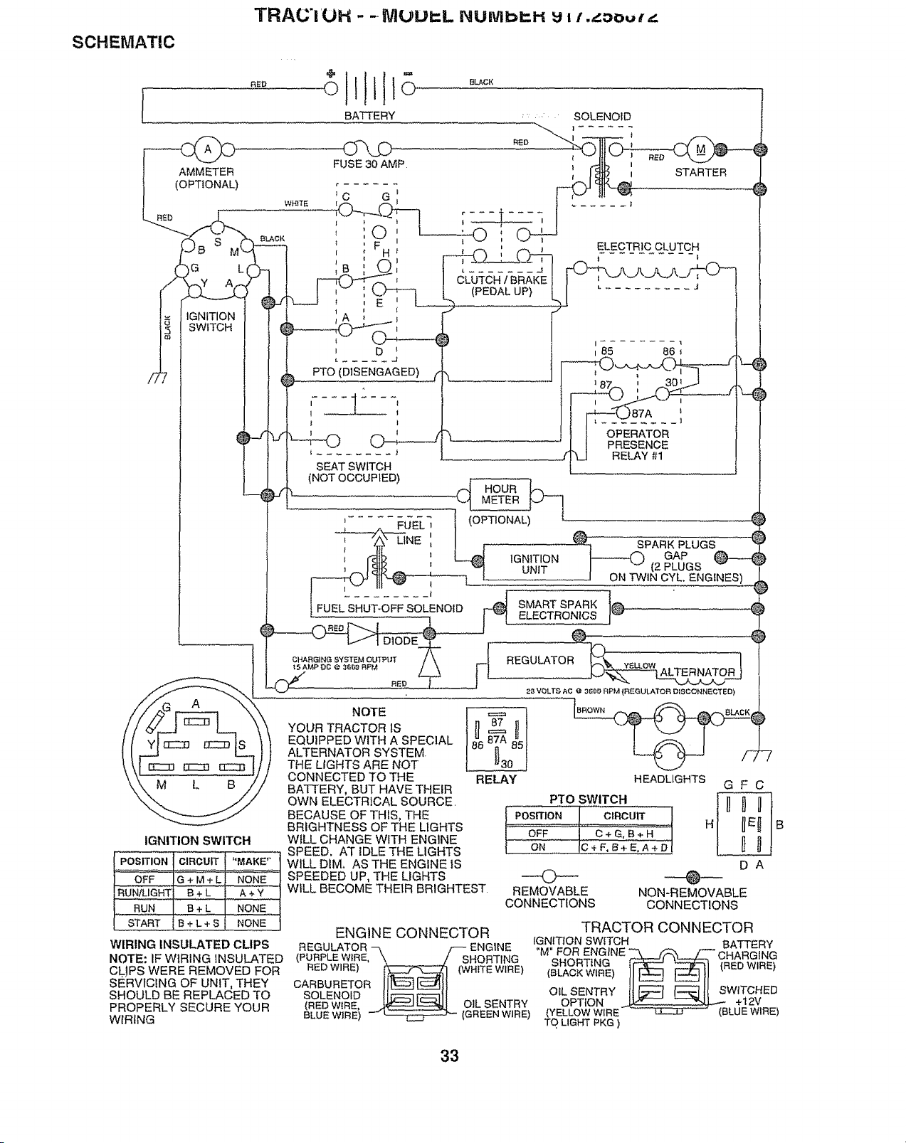
TRAC'i 'UH - - NIUUIr..L NUtVlb_H _ =/ ._:_ouA'_
SCHEMATIC
AMMETER
(OPTIONAL)
G L
IGNITION
SWITCH
IGNITION SWITCH
POSITION
OFF
RUN/LIGHT B + L .... A + Y
RUN B + L NONE
START B + L + S NONE
WIRING INSULATED CLIPS
NOTE: IF WIRING INSULATED
CLIPS WERE REMOVED FOR
SERVICING OF UNIT, THEY
SHOULD BE REPLACED TO
PROPERLY SECURE YOUR
WIRING
NOTE
YOUR TRACTOR tS
EQUIPPED WITH A SPECIAL
ALTERNATOR SYSTEM.
THE UGHTS ARE NOT
CONNECTED TO THE
BATTERY, BUT HAVE THEIR
OWN ELECTRICAL SOURCE,
BECAUSE OF THIS, THE
BRIGHTNESS OF THE LIGHTS
WILL CHANGE WITH ENGINE
SPEED. AT IDLE THE LIGHTS
WiLL DIM. AS THE ENGINE IS
SPEEDED UP, THE LIGHTS
WILL BECOME THEIR BRIGHTEST
RELAY HEADLIGHTS
)
PTO SWITCH
--(>--
REMOVABLE
CONNECTIONS
GFC
DA
O
NON-REMOVABLE
CONNECTIONS
ENGINE CONNECTOR TRACTOR CONNECTOR
IGNITION SWITCH
REGULATOR _ F ENG1NE . BATTERY
(PURPLEWIRE, "\ / SHORTING M" FOR ENGINE _ _ /_ CHARGING
RED WIRE) _ (WHITE WIRE) (BLACKWtRE)SHORTING_-_11_ __ 11 (RED WIRE)
CARBURETOR II_L__J_ll
_ROELEwNOIED. __ OIL SENTRY OILoPTIoNSENTRY_it _ _ I! SWITCHED+12V
BLUE WIREi _ _ (GREENWIRE) (YELLOW WIRE- (BLUE WIRE)
TO LIGHT PKG )
33
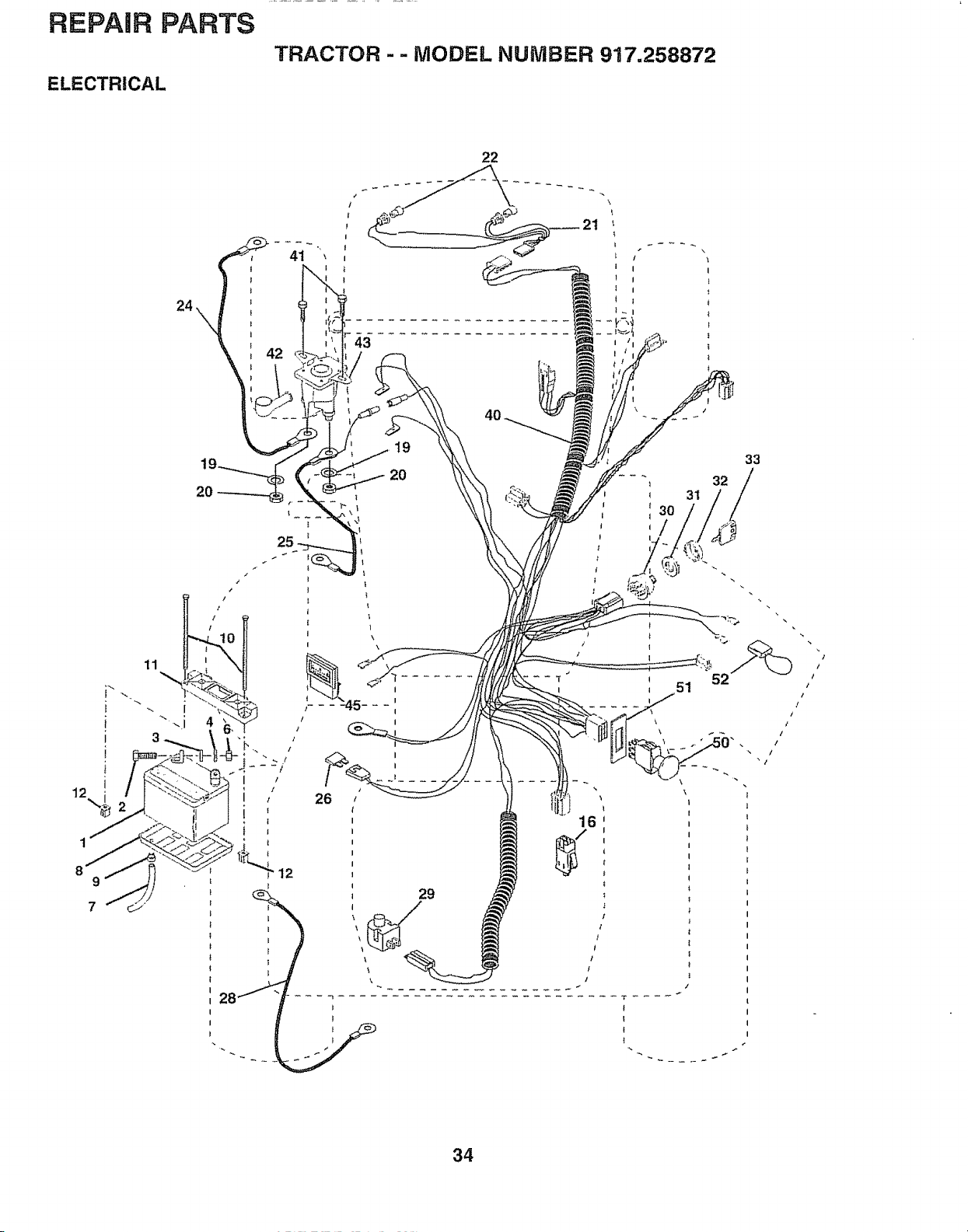
REPAIR PARTS
ELECTRICAL
TRACTOR -- MODEL NUMBER 917.258872
22
42
/
19
20
12
34
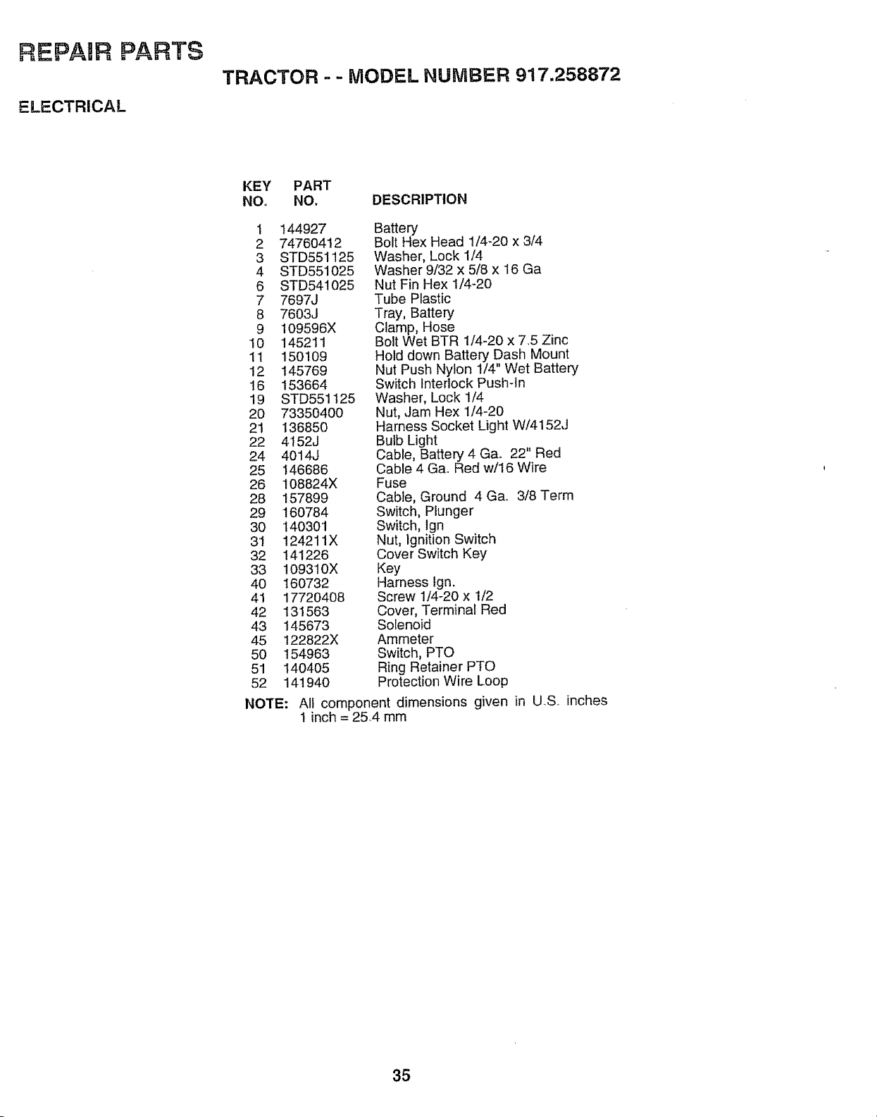
REPAaR PARTS
ELECTRICAL
TRACTOR - - MODEL NUMBER 917,258872
KEY PART
NO,, NO. DESCRIPTION
! 144927
2 74760412
3 STD551125
4 STD551025
6 STD54!025
7 7697J
8 7603J
9 109596X
10 145211
1t 150109
12 145769
16 153664
19 STD551125
20 7335040O
21 136850
22 4t 52J
24 4014J
25 146686
26 108824X
28 157899
29 160784
30 140301
3'1 124211X
32 141226
33 109310X
40 160732
41 17720408
42 131563
43 145673
45 122822X
50 154963
51 I40405
52 141940
NOTE:
Battery
Bolt Hex Head 1/4-20 x 3/4
Washer, Lock 1/4
Washer 9/32 x 5/8 x 16 Ga
Nut Fin Hex 1/4-20
Tube Plastic
Tray, Battery
Clamp, Hose
Bolt Wet BTR 1/4-20 x 745 Zinc
Hold down Battery Dash Mount
Nut Push Nylon 1/4" Wet Battery
Switch Interlock Push-In
Washer, Lock 1/4
Nut, Jam Hex 1/4-20
Harness Socket Light W/4152J
Bulb Light
Cable, Battery 4 Ga. 22" Red
Cable 4 Ga. Red w/16 Wire
Fuse
Cable, Ground 4 Ga. 3/8 Term
Switch, Plunger
Switch, Ign
Nut, Ignition Switch
Cove r Switch Key
Key
Harness tgn.
Screw 1/4-20 x 1/2
Cover, Terminal Red
Solenoid
Ammeter
Switch, PTO
Ring Retainer PTO
Protection Wire Loop
All component dimensions given in U.S. inches
! inch = 25.4 mm
35
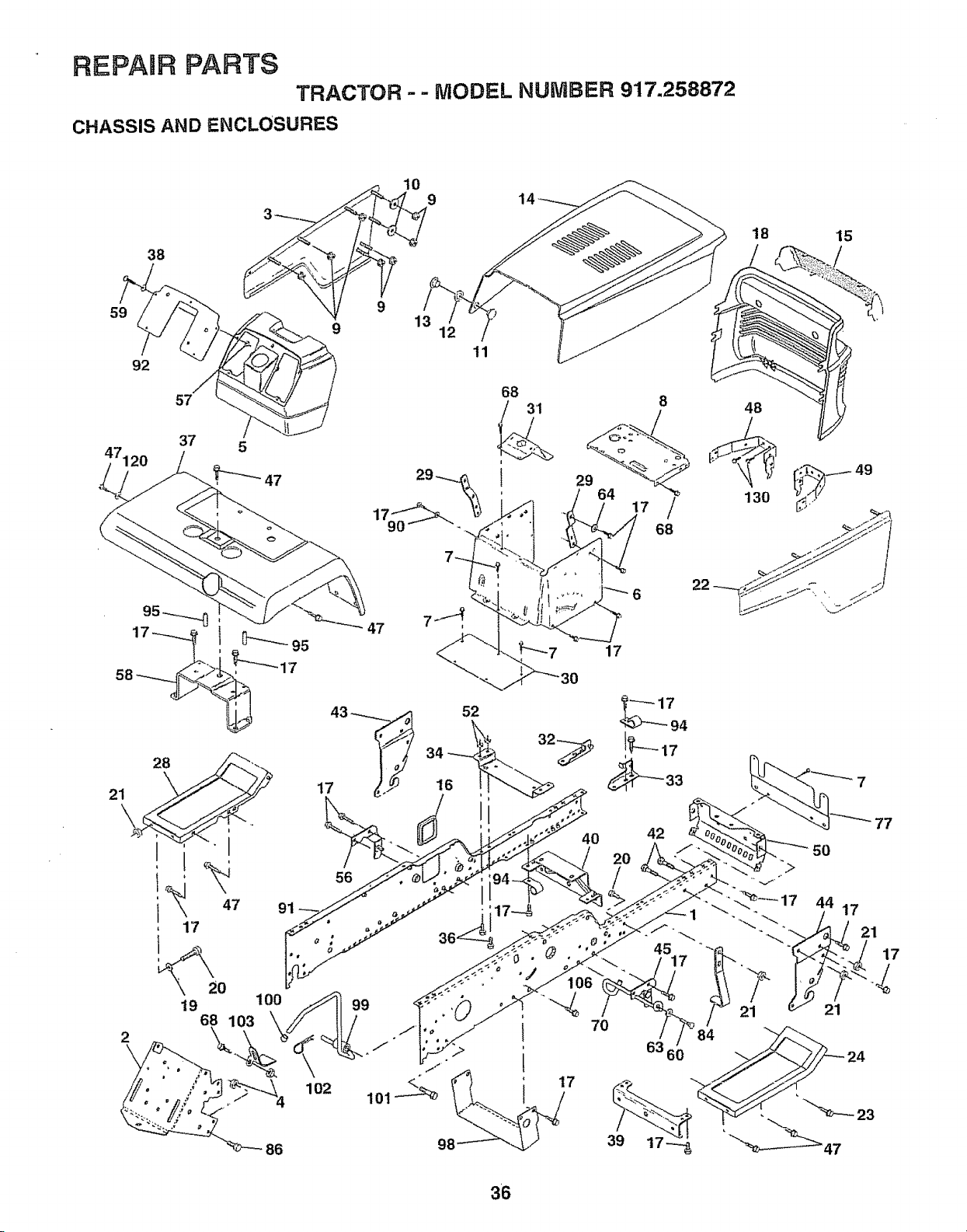
REPAnR PARTS
TRACTOR -- MODEL NUMBER 917.258872
CHASSIS AND ENCLOSURES
38
10
9
18
/
15
59
92
57
37 5
47120
_''_47
2
86
13 1:
11
8
17 /
68
47
56
34
16
17
52
I
7
94
42
102
70
77
36
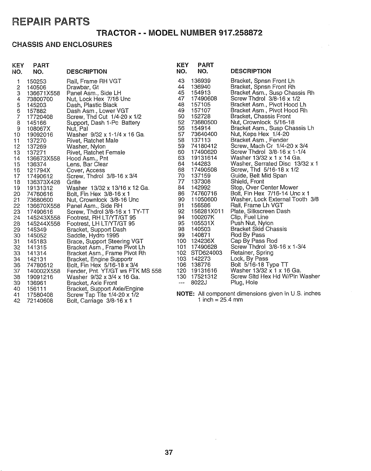
REPAUR PARTS
TRACTOR - - MODEL NUMBER 917.258872
CHASSIS AND ENCLOSURES
KEY PART KEY PART
NO. NO, DESCRIPTION NO, NO. DESCRIPTION
1 t50253 Rail, Frame RH VGT 43 136939
2 140506 Drawbar, Gt 44 136940
3 136671X558 Panel Asm. Side LH 45 154913
4 73800700 Nut, Lock Hex 7/16 Unc 47 17490608
5 145203 Dash, Plastic Black 48 157105
6 157882 Dash Asm., Lower VGT 49 157107
7 17720408 Screw, Thd Cut 1/4-20 x 1/2 50 152728
8 I45166 Support, Dash 1-Pc Battery 52 73680500
9 t08067X Nut, Pal 56 154914
10 19092016 Washer 9/32 x 1-1/4 x 16 Ga. 57 73640400
It 137270 Rivet, Ratchet Male 58 137113
12 137269 Washer, Nylon 59 74180412
13 !37271 Rivet, Ratchet Female 60 17490620
14 136673X558 Hood Asm., Pnt 63 19131614
t5 136374 Lens, Bar Clear 64 144283
t6 I21794X Cover, Access 68 17490508
t7 17490612 Screw, Thdrol 3/8-I6 x 3/4 70 137159
18 136373X428 Grille 77 137308
19 19131312 Washer 13/32 x 13/16 x 12 Ga. 84 142992
20 74760616 Bolt, Fin Hex 3/8-16 x 1 86 74760716
21 73680600 Nut, Crownlock 3/8-16 Unc 90 11050600
22 136670X558 Panel Asm., Side RH 91 156586
23 17490616 Screw, Thdrol 3/8-16 x 1 TY-TT 92 156281X011
24 t45243X558 Footrest, RH LT/YTiGT 95 94 100207K
28 145244X558 Footrest, LH LT/YT/GT 95 95 105531X
29 145349 Bracket, Support Dash 98 140503
30 145052 Saddle, Hydro !995 99 140871
3t 145183 Brace, Support Steering VGT 100 124236X
32 141315 Bracket Asm, Frame Pivot Lh 101 17490628
33 141314 Bracket Asm., Frame Pivot Rh 102 STD624003
34 142131 Bracket, Engine Supportr 103 142273
36 74780512 Bolt, Fin Hex 5/16-18 x 3/4 106 138776
37 t40002X558 Fender, Pnt. YT/GT ws FTK MS 558 120 19131616
38 19091216 Washer 9!32x3/4x16Gao 130 17521312
39 136961 Bracket, Axle Front --- 8022J
40 t56111 Bracket, Support Axle/Engine
41 17580408 Screw Tap Tite !/4-20 x 1/2
42 72140608 Bolt, Carriage 3/8q6 x I
Bracket, Spnsn Front Lh
Bracket, Spnsn Front Rh
Bracket Asm., Susp Chassis Rh
Screw Thdrol 3/8-16 x 1/2
Bracket Asm,, Pivot Hood Lh
Bracket Asm., Pivot Hood Rh
Bracket, Chassis Front
Nut, Crownlock 5/16-18
Bracket Asm,., Susp Chassis Lh
Nut, Keps Hex 1/4-20
Bracket As.rn., Fender
Screw, Mach Cr 1/4-20 x 3/4
Screw Thdrol 3/8-16 x 1-1/4
Washer 13/32 x 1 x 14 Gao
Washer, Serrated Disc t3/32 x 1
Screw, Thd 5/16-18 x 1/2
Guide, Belt Mid Span
Shield, Front
Stop, Over Center Mower
Bolt, Fin Hex 7/16-14 Unc x 1
Washer, Lock External Tooth 3/8
Rail, Frame Lh VGT
Plate, Silkscreen Dash
Clip, Fuel Line
Push Nut, Nylon
Bracket Skid Chassis
Rod By Pass
Cap By Pass Rod
Screw Thdrol 3/8-16 x 1-3/4
Retainer, Spring
Lock, By Pass
Bolt 5/16-18 Type "IF
Washer 13/32 x 1 x 16 Ga.
Screw Sltd Hex Hd W/Pin Washer
Plug, Hole
NOTE: Al! component dimensions given in U,S, inches
! inch = 25,4 mm
37
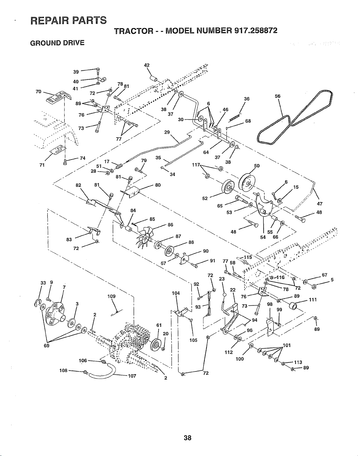
REPAIR PARTS
GROUND DRIVE
TRACTOR - - MODEL NUMBER 917.258872
109 "'_
3 \'..\
.^^ ..J "._',', ,_=."
I O8
"---'-___-'--" 107
104
61
2
I
105
22
112
10o
38
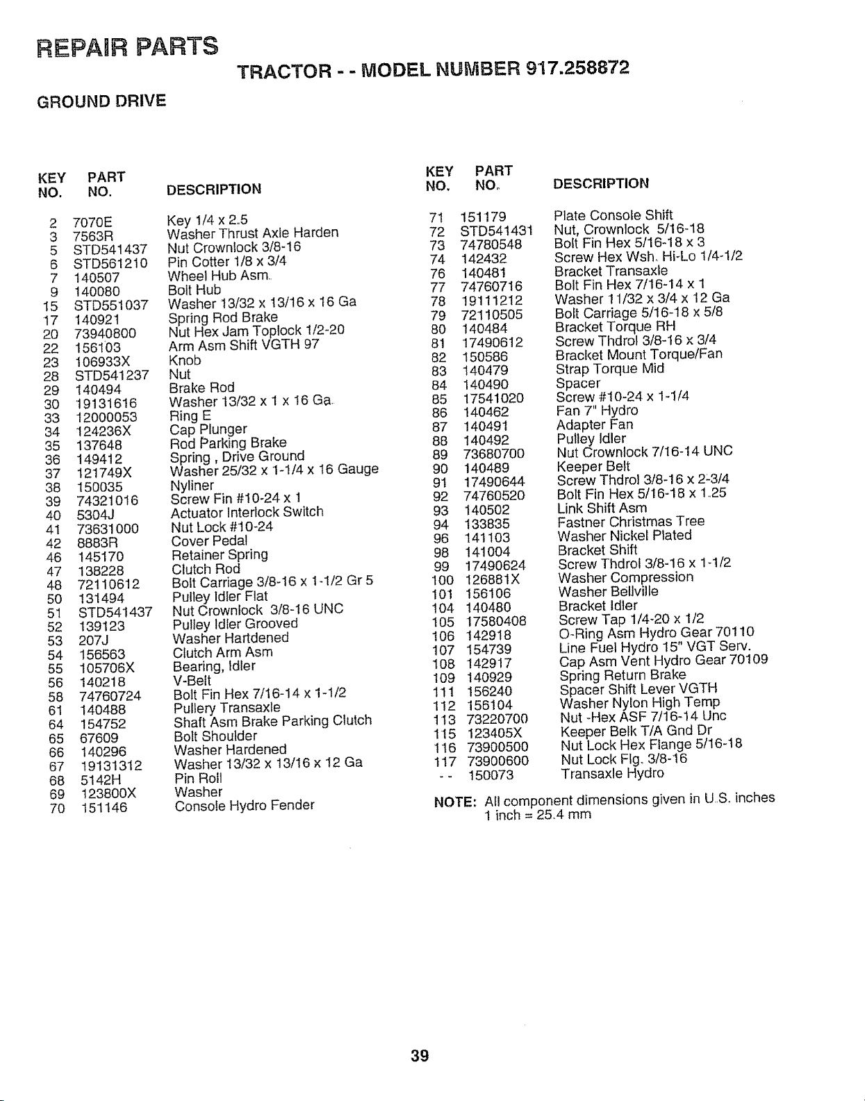
REPAIR PARTS
GROUND DRIVE
TRACTOR - - MODEL NUMBER 917.258872
KEY PART
NO. NO.
2 7070E
3 7563R
5 STD541437
6 STD561210
7 140507
9 140080
15 STD551037
17 140921
20 73940800
22 1561'03
23 106933X
28 STD541237
29 140494
3O 19131616
33 12OO0053
34 124236X
35 137648
36 149412
37 t21749X
38 150035
39 74321016
4O 5304J
41 736310O0
42 8883R
46 145170
47 138228
48 72110612
5O 131494
51 STD541437
52 139123
53 207J
54 156563
55 105706X
56 140218
58 74760724
61 140488
64 154752
65 67609
66 140296
67 19131312
68 5142H
69 123800X
70 151146
DESCRIPTION
Key 1/4 x 2..5
Washer Thrust Axle Harden
Nut Crownlock 3/8-16
Pin Cotter 1/8 x 3/4
Wheel Hub Asm.
Bolt Hub
Washer t 3/32 x 13/16 x 16 Ga
Spring Rod Brake
Nut Hex Jam Toplock 1/2-20
Arm Asm Shift VGTH 97
Knob
Nut
Brake Rod
Washer 13/32 x 1 x 16 G&
Ring E
Cap PLunger
Rod Parking Brake
Spring, Drive Ground
Washer 25/32 x 1-1/4 x 16 Gauge
Nyliner
Screw Fin #10-24 x 1
Actuator Interlock Switch
Nut Lock #t 0-24
Cover Pedal
Retainer Spring
Clutch Rod
Bolt Carriage 3/8-16 x 1-1/2 Gr 5
Pulley Idler Flat
Nut Crownlock 3/8-16 UNC
Pulley Idler Grooved
Washer Hartdened
Clutch Arm Asm
Bearing, Idler
V-Belt
Bolt Fin Hex 7/I6-14 x 1-1/2
Pulfery Transaxle
Shaft Asm Brake Parking Clutch
Bolt Shoulder
Washer Hardened
Washer 13!32 x 13/16 × 12 Ga
Pin Roll
Washer
Console Hydro Fender
KEY PART
NO. NOo DESCRIPTION
71 151179
72 STD54t431
73 74780548
74 142432
76 140481
77 74760716
78 19111212
79 7211O5O5
8O 14O484
81 17490612
82 15O586
83 140479
84 14O490
85 1754102O
86 140462
87 140491
88 140492
89 7368O70O
90 140489
91 17490644
92 74760520
93 140502
94 133835
96 141103
98 141004
99 17490624
100 126881X
101 156106
104 14O480
105 1758O4O8
106 142918
107 154739
108 142917
109 140929
tll 156240
112 156104
1t3 73220700
115 123405X
116 73900500
I17 739006OO
-- 150073
Plate Console Shift
Nut, Crownlock 5f16-18
Bolt Fin Hex 5/16-18 x 3
Screw Hex Wsh. Hi-Lo 1/4-1/2
Bracket Transaxte
Bolt Fin Hex 7/16-14 x 1
Washer 11/32 x 3/4 x 12 Ga
Bolt Carriage 5/16-18 x 5/8
Bracket Torque RH
Screw Thdrol 3/8-16 x 3/4
Bracket Mount Torque/Fan
Strap Torque Mid
Spacer
Screw #10-24 x 1-1/4
Fan 7" Hydro
Adapter Fan
Pulley Idler
Nut Crownlock 7/16-14 UNC
Keeper Belt
Screw Thdrol 3/8-16 x 2_3/4
Bolt Fin Hex 5116-18 x 125
Link Shift Asm
Fastner Christmas Tree
Washer Nickel Plated
Bracket Shift
Screw Thdrol 3/8-16 x 1-1/2
Washer Compression
Washer BelJville
Bracket Idler
Screw Tap 1/4-20 x 1/2
O-Ring Asm Hydro Gear 70110
Line Fuel Hydro 15" VGT Serv.
Cap Asm Vent Hydro Gear 70109
Spdng Return Brake
Spacer Shift Lever VGTH
Washer Nylon High Temp
Nut -Hex ASF 7116-14 Unc
Keeper Belk T/A Gnd Dr
Nut Lock Hex Flange 5t16-t8
Nut Lock Fig, 3/8-16
Transaxle Hydro
NOTE: All component dimensions given in U,,S, inches
1 inch = 25.4 mm
39
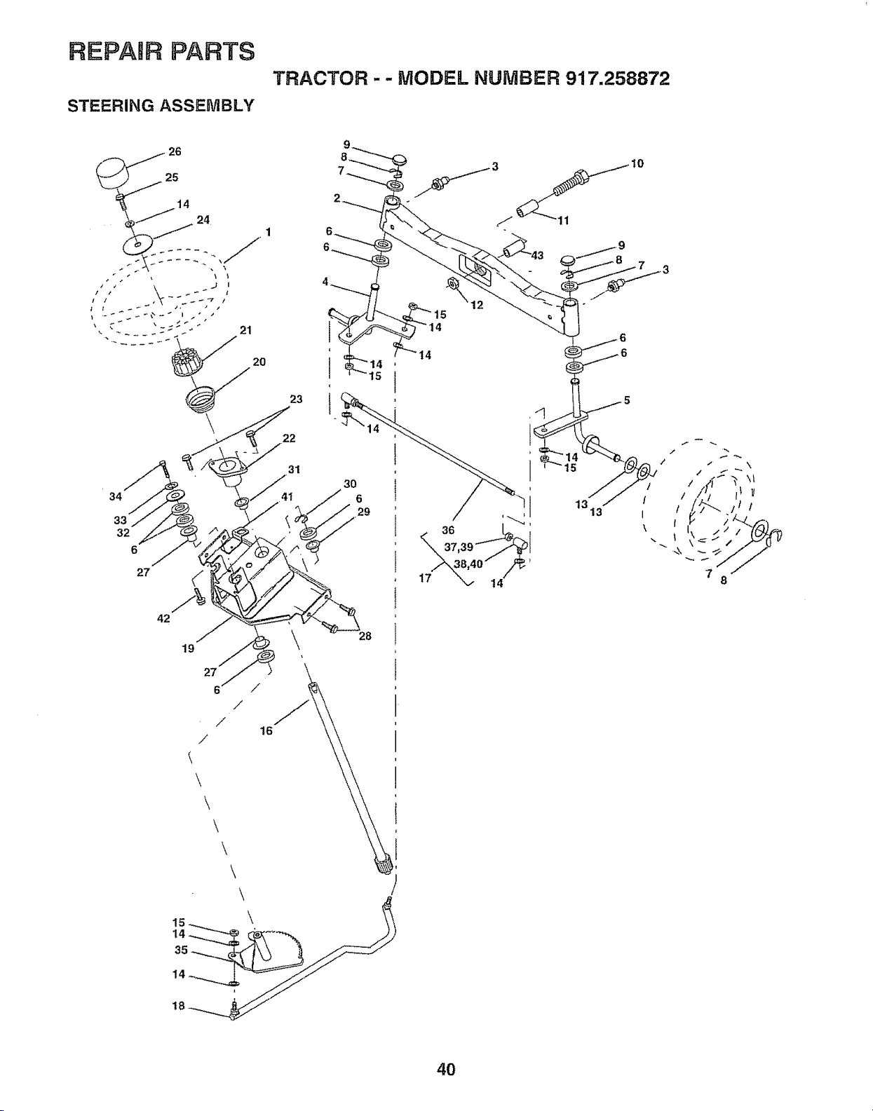
REPAIR PARTS
STEERING ASSEMBLy
TRACTOR - - MODEL NUMBER 917.258872
t0
34
33
32
6
27
19
27
6
/
/
/
/
t6
23
22
31
29
28
15
14
t4
1313
\
\
\
\
\
\
40
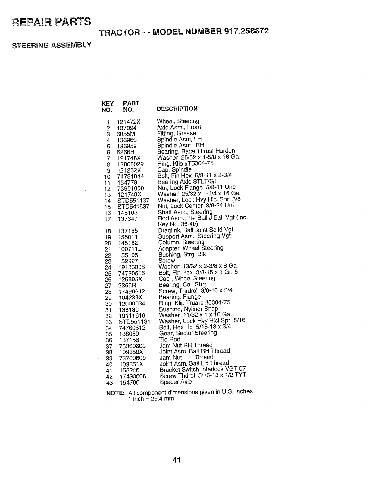
REPAIR PARTS
STEERING ASSEMBLY
TRACTOR - - MODEL NUMBER 917.258872
KEY PART
NO, NO. DESCRIPTION
1 121472X
2 137094
3 6855M
4 136960
5 136959
6 6266H
7 121748X
8 12000029
9 121232X
10 74781O44
11 154779
12 73901000
13 121749X
14 STD551137
15 STD541537
16 145103
17 137347
18 137155
t9 156011
20 145182
21 100711L
22 155105
23 152927
24 19133808
25 74780616
26 126805X
27 3366R
28 17490612
29 104239X
30 12000034
31 138136
32 19111610
33 STD551t31
34 74760512
35 138059
36 137156
37 73360600
38 109850X
39 73700600
40 109851X
4I 155246
42 17490508
43 154780
Wheel, Steering
Axle Asm. Front
Fitting, Grease
Spindle Asm, LH
Spindle Asm., RH
Bearing, Race Thrust Harden
Washer 25/32 x 1-5/8 x 16 Ga..
Ring, Kiip ,#'1"5304-75
Cap, Spindle
Bolt, Fin Hex 5/8-11 x 2-3/4
Bearing Axle STLT/GT
Nut, Lock Flange 5/8-11 Uric
Washer 25132 x 1-1/4 x 16 Ga.
Washer, Lock Hvy Hlcl Spr 3/8
Nut, Lock Center 3/8424 Unf
Shaft Asmo, Steering
Rod Asm., Tie Ball J Ball Vgt (Inc
Key No 36-40)
Draglink, Ball Joint Solid Vgt
Support Asmo, Steering Vgt
Column, Steering
Adapter, Wheel Steering
Bushing, Strg BIk
Screw
Washer 13/32 x 2-3/8 x 8 G&
Bolt, Fin Hex 3/8-16 x 1 Gr 5
Cap, Wheel Steering
Bearing, Col Strg.
Screw, Thrdrol 3/8-16 x 3/4
Bearing, Flange
Ring, Klip Truarc #5304-75
Bushing, Nyliner Snap
Washer 11/32 x 1 x 10 Ga.
Washer, Lock Hvy Htcl Spr 5/16
Bo_t, Hex Hd 5/t6-18 x 3/4
Gear, Sector Steering
Tie Rod
Jam Nut RH Thread
Joint Asm Ball RH Thread
Jam Nut LH Thread
Joint Asm Ball LH Thread
Bracket Switch Interlock VGT 97
Screw Thdrol 5/16-18 x 1/2 TYT
Spacer Axle
NOTE: All component dimensions given in U.S. inches
1 inch = 2&4 mm
41
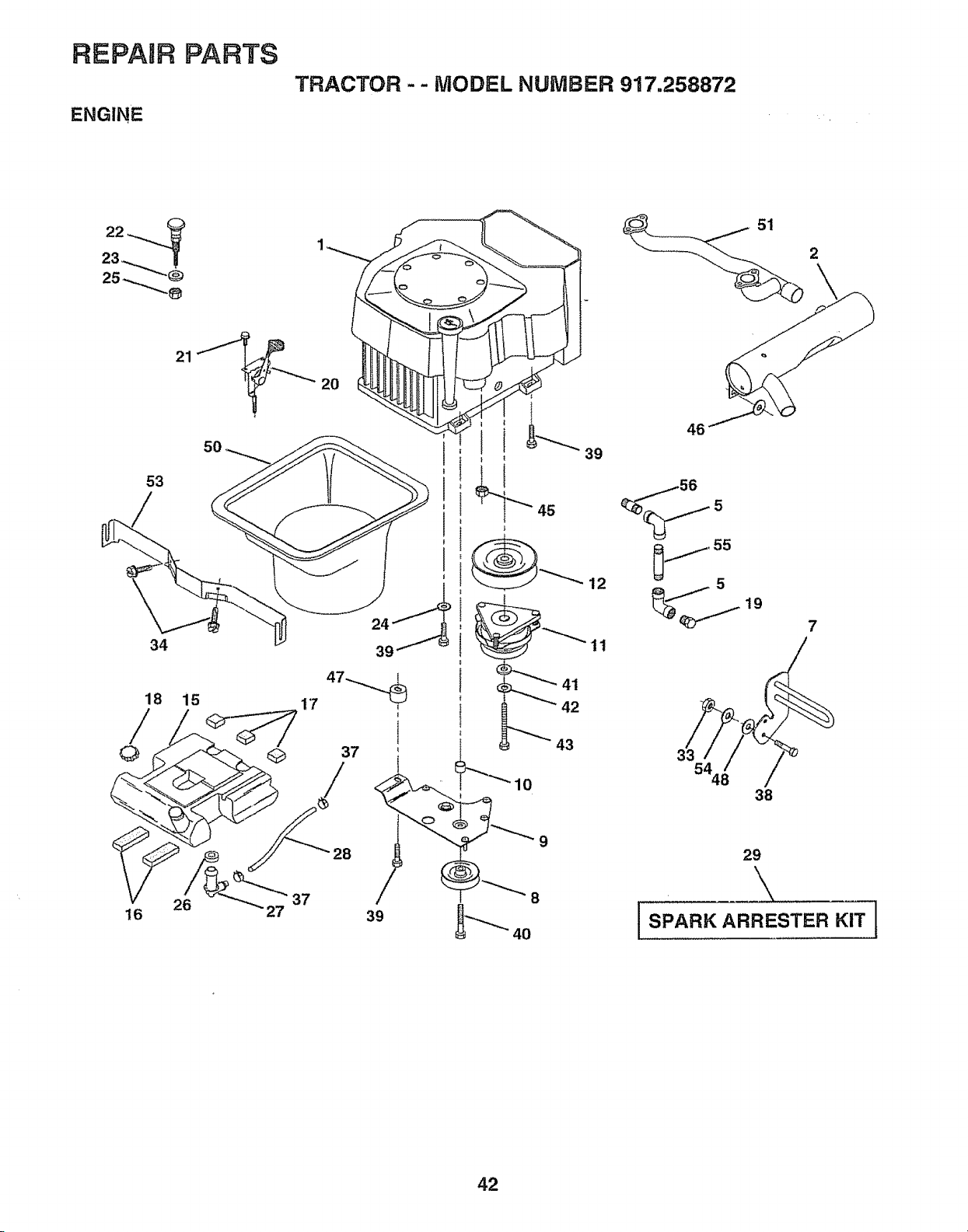
REPAIR pARTS TRACTOR" MODEL NUMBER 917,258872
ENGINE
2
21
53
34
5O
18 15
20
17
_'_39
45
12
11
56 5
, 55
19
3 5448
38
7
!
29
16
37
39
4O
42
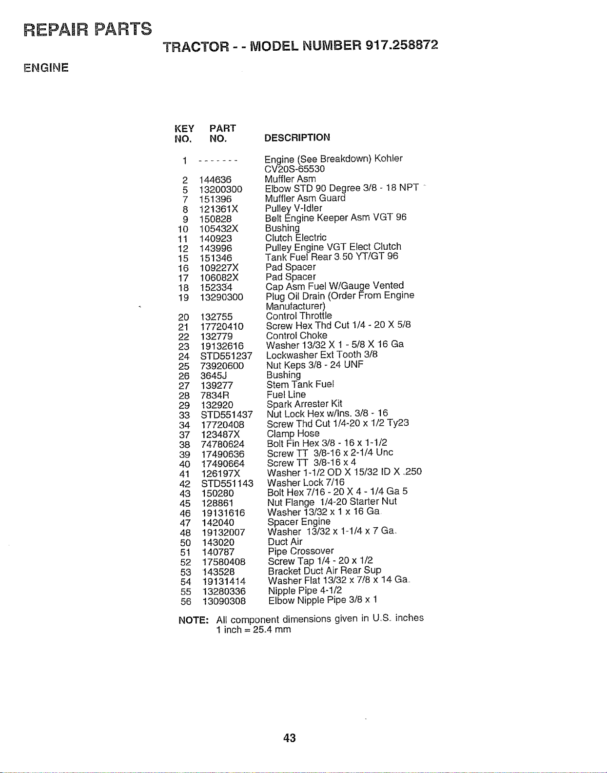
REPAIR PARTS
ENGINE
TRACTOR - - MODEL NUMBER 9!7.258872
KEY PART
NO, NO. DESCRIPTION
.......
2 144636
5 13200300
7 151396
8 121361X
9 150828
10 105432X
1t 140923
t2 143996
!5 151346
16 109227X
17 106082X
I8 152334
19 13290300
20 132755
21 1772041O
22 132779
23 19132616
24 STD551237
25 73920600
26 3645J
27 139277
28 7834R
29 132920
33 STD551437
34 17720408
37 123487X
38 74780624
39 17490636
40 17490664
41 126197X
42 STD551143
43 150280
45 128861
46 19131616
47 142040
48 19132007
50 143020
5t 140787
52 17580408
53 143528
54 19131414
55 13280336
56 13090308
Engine (See Breakdown) Kohter
CV20S-65530
Muffler Asm
Elbow STD 90 Degree 318 - t8 NPT "
Muffler Asm Guard
Pulley V-Idler
Belt Engine Keeper Asm VGT 96
Bushing
Clutch Electdc
Pulley Engine VGT Elect Clutch
Tank Fuel Rear 3, 50 YT/GT 96
Pad Spacer
Pad Spacer
Cap Asm Fuel W/Gauge Vented
Plug Oil Drain (Order From Engine
Manufacturer)
Control Throttle
Screw Hex Thd Cut 1/4 - 20 X 5/8
Control Choke
Washer 13/32 X 1 - 5/8 X 16 Ga
Lockwasher Ext Tooth 3/8
Nut Keps 3/8 - 24 UNF
Bushing
Stem Tank Fuel
Fuel Line
Spark Arrester Kit
Nut Lock Hex w/Ins, 3/8 - 16
Screw Thd Cut 1/4-20 x 'I/2 Ty23
Clamp Hose
Bolt Fin Hex 3/8 - 16 x 1-1/2
Screw TT 3/8-16 x 2-1/4 Unc
Screw TT 318-16 x 4
Washer 1-1/20D X t5!32 ID X .250
Washer Lock 7/16
Bolt Hex 7/16 - 20 X 4 - t/4 Ga 5
Nut Flange 1/4-20 Starter Nut
Washer 13/32 x 1 x 16 Ga
Spacer Engine
Washer 13/32 x 1-1/4 x 7 Ga,
Duct Air
Pipe Crossover
Screw Tap 1/4 - 20 x 1/2
Bracket Duct Air Rear Sup
Washer Flat 13/32 x 7/8 x 14 Ga,,
Nipple Pipe 4-1/2
Elbow Nipple Pipe 3/8 x 1
NOTE: All component dimensions given in U,,S.,inches
1 inch = 25.4 mm
43
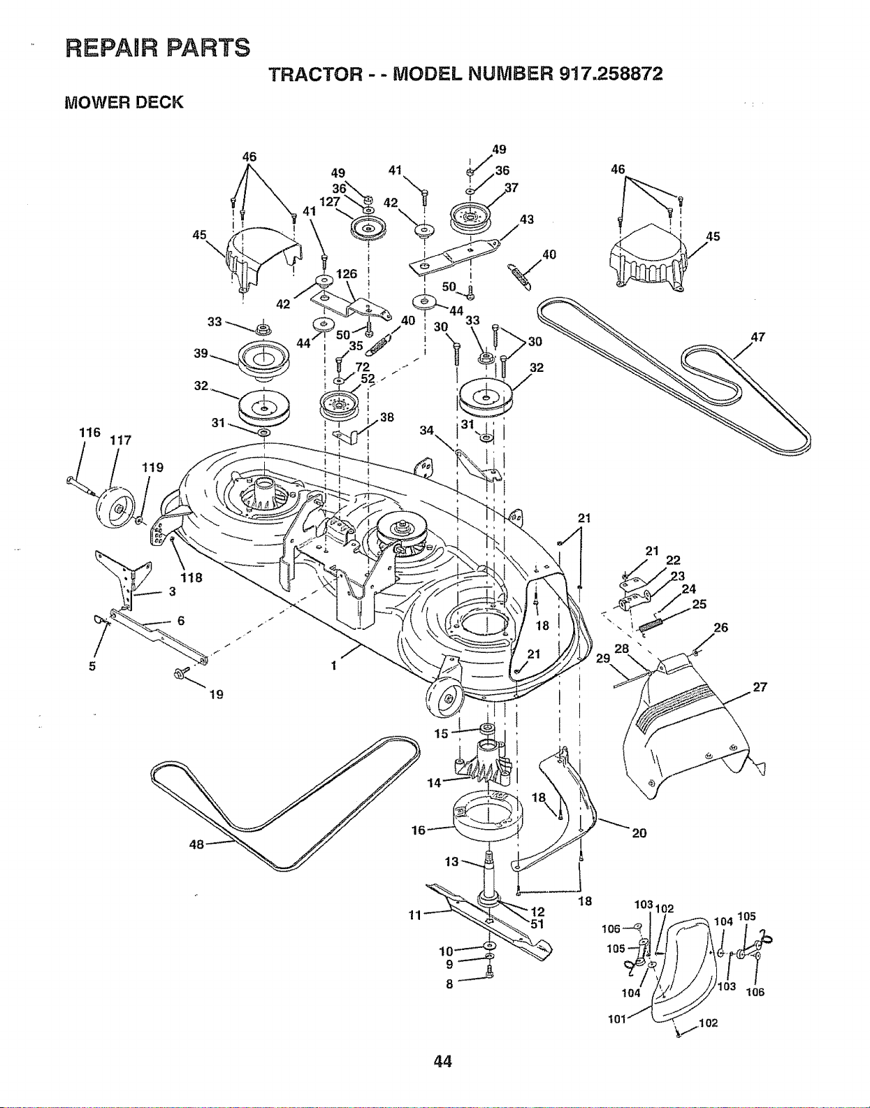
REPAIR PARTS
MOWER DECK
TRACTOR - - MODEL NUMBER 917.258872
116
1!7
119
46
i
15
21
I
21
26
27
9
8
18
103
1064 1102 104 105,
1Ol
44
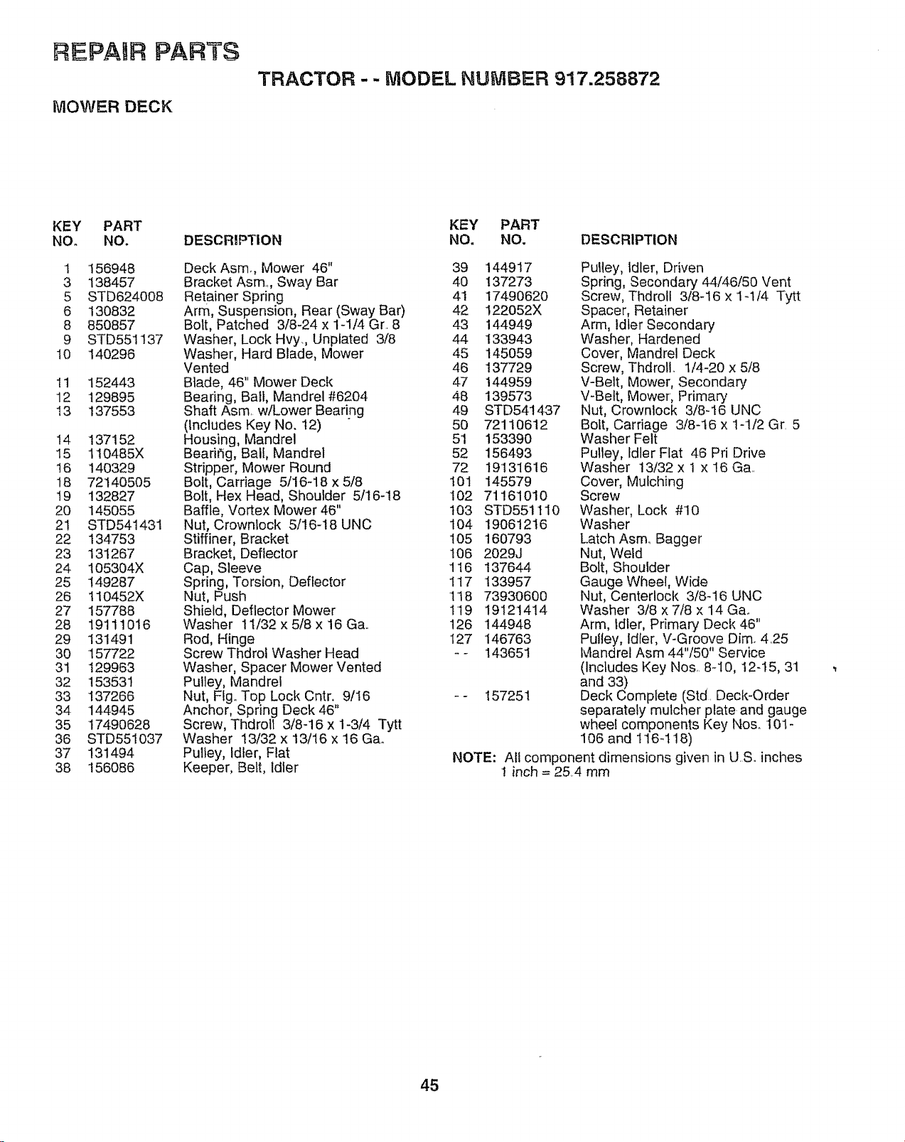
REPAmRPARTS
MOWER DECK
TRACTOR - - MODEL NUMBER 917.258872
KEY PART
NO. NO.
1 156948
3 138457
5 STD624008
6 130832
8 850857
9 STD551137
10 140296
11 152443
12 129895
13 137553
!4 137152
I5 110485X
16 140329
t8 721405O5
!9 132827
20 145055
21 STD541431
22 134753
23 131267
24 105304X
25 149287
26 110452X
27 157788
28 19111016
29 131491
30 157722
31 129963
32 153531
33 137266
34 144945
35 17490628
36 STD551037
37 131494
38 156086
DESCRIPTION
Deck Asm., Mower 46"
Bracket Asm., Sway Bar
Retainer Spring
Arm, Suspension, Rear (Sway Bar)
Bolt, Patched 3/8-24 x 1-1/4 Gr. 8
Washer, Lock Hvy., Unptated 3/8
Washer, Hard Blade, Mower
Vented
Blade, 46" Mower Deck
Bearing, Bail, Mandrel #6204
Shaft Asm w!Lower Bearing
(Includes Key No. 12)
Housing, Mandrel
Bearirig, Bali, Mandrel
Stripper, Mower Round
Bolt, Carriage 5t16_18 x 5/8
Bolt, Hex Head, Shoulder 5t16-18
Baffle, Vortex Mower 46"
Nut, Crownlock 5/16-18 UNC
Stiffiner, Bracket
Bracket, Deflector
Cap, Sleeve
Spring, Torsion, Deflector
Nut, Push
Shield, Deflector Mower
Washer 1t/32 x 5t8 x 16 Ga..
Rod, Hinge
Screw Thdrol Washer Head
Washer, Spacer Mower Vented
Pulley, Mandrel
Nut, Fig,. Top Lock Cntr. 9/I6
Anchor, Spring Deck 46"
Screw, Thdroll 3/8-i6 x 1-3/4 Tytt
Washer 13/32 x 13/16 x 16 Gao
Pulley, Idler, Flat
Keeper, Belt, Idler
KEY PART
NO. NO. DESCRIPTION
39 144917
4O 137273
41 17490620
42 I22052X
43 144949
44 133943
45 145059
46 137729
47 144959
48 139573
49 STD541437
50 72110612
5t 153390
52 156493
72 19'I31616
101 145579
102 71161010
t03 STD551110
104 19061216
105 160793
106 2029J
116 137644
117 133957
118 73930600
119 19121414
126 144948
I27 146763
_- 143651
157251
Pulley, idler, Driven
Spring, Secondary 44/46/50 Vent
Screw, Thdrolt 3/8-16 x 1-114 Tytt
Spacer, Retainer
Arm, Idler Secondary
Washer, Hardened
Cover, Mandrel Deck
Screw, Thdrotl. 1/4-20 x 5/8
V-Belt, Mower, Secondary
V-Belt, Mower', Primary
Nut, Crownlock 3/8-16 UNC
Bolt, Carriage 3/8-16 x 1-1/2 Gr. 5
Washer Felt
Pulley, Idler Flat 46 Pri Drive
Washer 13/32 x 1 x 16 Ga..
Cover, Mulching
Screw
Washer, Lock #10
Washer
Latch Asm_ Bagger"
Nut, Weld
Bolt, Shoulder
Gauge Wheel, Wide
Nut, Centerlock 3/8q6 UNC
Washer 3/8 x 7/8 x 14 Ga,.
Arm, Idler, Primary Deck 46"
Pulley, Idler, V-Groove Dim. 425
Mandrel Asm 44"/50" Service
(Includes Key Nos, 8-10, 12-15, 31
and 33)
Deck Complete (Std. Deck-Order
separately mulcher plate and gauge
wheel components Key Nos. 101-
106 and 116-118)
NOTE: Altcomponentdimensions givenin USoinches
1 inch = 25.4mm
45
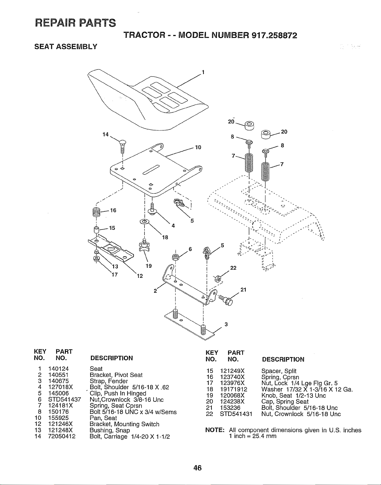
REPAgR PARTS
SEAT ASSEMBLY
TRACTOR -- MODEL NUMBER 917.258872
KEY PART
NO. NO.
1 140124
2 140551
3 140675
4 I27018X
5 145006
6 STD54t437
7 124181X
8 150176
10 155925
12 121246X
13 121248X
14 72050412
@_ 16
15
18
19
12
DESCRIPTION
Seat
Bracket, Pivot Seat
Strap, Fender
Bolt, Shoulde[ 5/16-18 X ,62
Clip, Push In Hinged
Nut,Crownlock 3/8-16 Unc
Spring, Seat Cprsn
Bolt 5/16-18 UNC x 3/4 w/Sems
Pan, Seat
Bracket, Mounting Switch
Bushing, Snap
Bolt, Carriage 1/4-20 X 1-!/2
10
5
4
KEY PART
NO. NO. DESCRIPTION
15 121249X
16 123740X
17 123976X
18 19171912
19 120068X
20 124238X
21 153236
22 STD541431
Spacer, Split
Spring, Cprsn
Nut, Lock 1/4 Lge Fig Gr. 5
Washer 17/32 X 1-3/16 X 12 Ga.
Knob, Seat 1/2-13 Unc
Cap, Spring Seat
Bolt, Shoulder 5/1G!8 Unc
Nut, Crownlock 5/16-18 Unc
NOTE: All component dimensions given in U.S. inches
1 inch = 2&4 mm
46
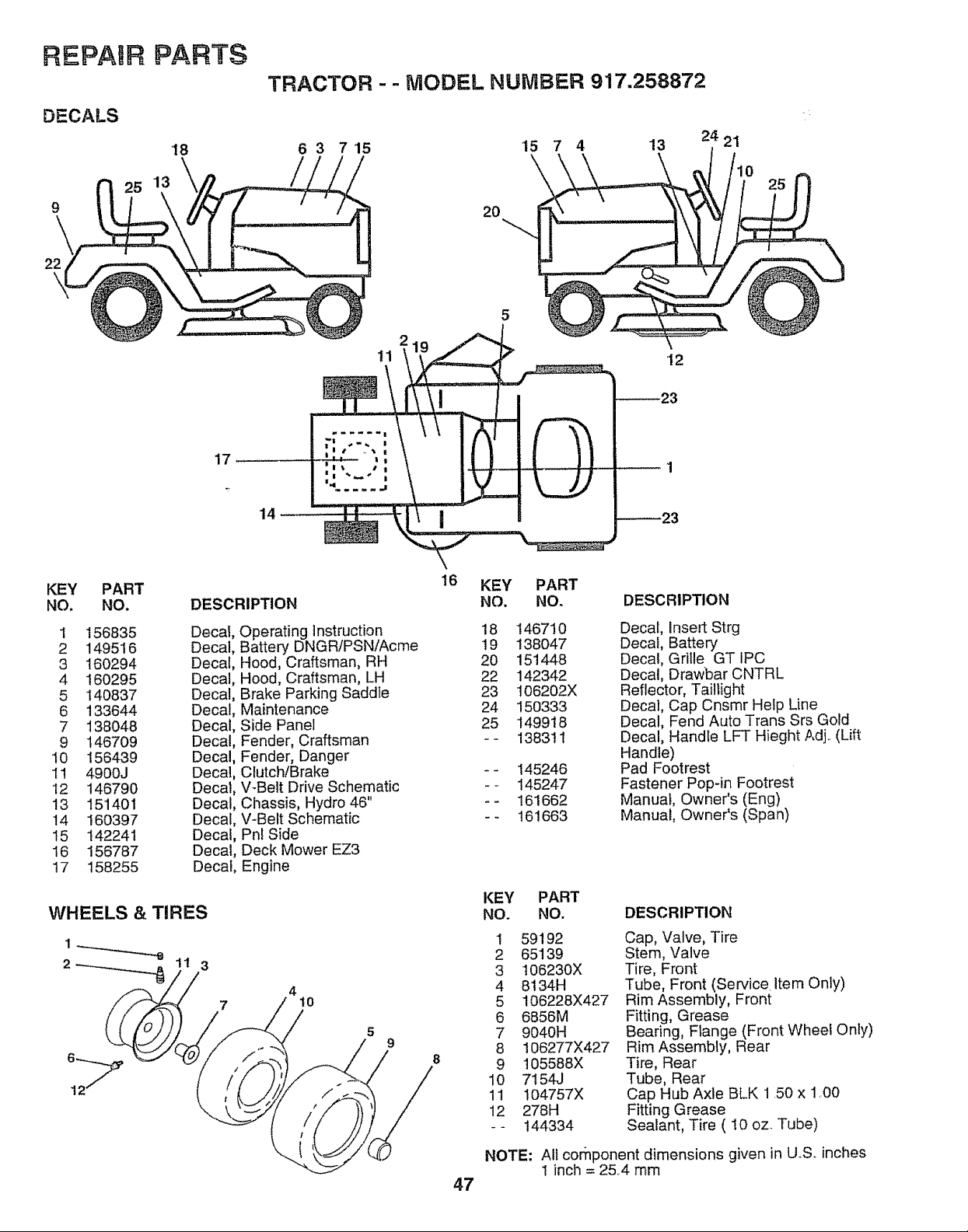
REPAtiR PARTS
DECALS
'18
TRACTOR - - MODEL NUMBER 917.258872
6 3 7'15 15 7 4 13
24 21
9
\
22
20
5
11
12
17
14
KEY
NO,
PART
NO.
1 156835
2 149516
3 160294
4 160295
5 140837
6 133644
7 138048
9 146709
I0 156439
11 4900J
12 146790
13 15'1401
14 160397
15 142241
16 156787
17 158255
DESCRIPTION
Decal, Operating Instruction
Decal, Battery DNGR/PSN/Acme
Decal, Hood, Craftsman, RH
Decal, Hood, Craftsman, LH
Decal, Brake Parking Saddte
Decal, Maintenance
Decal, Side Panet
Decal, Fender, Craftsman
Decal, Fender, Danger
Decal, Clutch!Brake
Decat, V-Belt Drive Schematic
Decal, Chassis, Hydro 46"
Decal, V-Belt Schematic
Decal, Phi Side
Decal, Deck Mower EZ3
Decal, Engine
4
10
5
9
\
16
KEY PART
NO, NO.
18 146710
19 138O47
20 151448
22 142342
23 I06202X
24 150333
25 149918
-- 138311
-- 145246
-- 145247
-- 161662
-- 161663
DESCRIPTION
Decal, Insert Strg
Decal, Battery
Decal, Grille GT IPC
Decal, Drawbar CNTRL
Reflector, Taillight
Decal, Cap Cnsmr Help Line
Decal, Fend Auto Trans Srs Gold
Decal, Handle LFT Hieght Adj.. (Lift
Handle)
Pad Footrest
Fastener Pop-in Footrest
Manual, Owner's (Eng)
Manual, Owner's (Span)
KEY PART
NO. NO.
DESCRIPTION
1 59192
2 65139
3 106230X
4 8134H
5 106228X427
6 6856M
7 9040H
8 106277X427
9 105588X
10 7154J
11 104757X
12 278H
-- 144334
Cap, Valve, Tire
Stem, Valve
Tire, Front
Tube, Front (Service. Item Only)
Rim Assembly, Front
Fitting, Grease
Bearing, Flange (Front Wheel Only)
Rim Assembly, Rear
Tire, Rear
Tube, Rear
Cap Hub Axle BLK 150 x 1.00
Fitting Grease
Sealant, Tire ( !0 oz. Tube)
NOTE: All cornponent dimensions given in U,,S, inches
1 inch = 25,4 mm
47
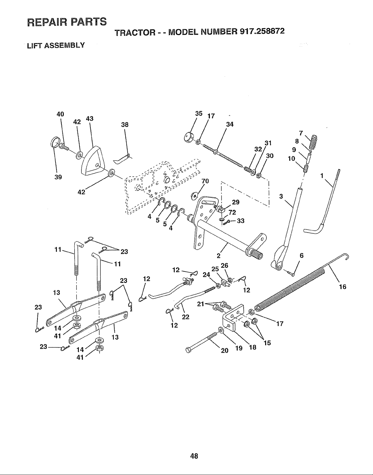
REPAmR PARTS
LIFT ASSEMBLY
TRACTOR -- MODEL NUMBER 917.258872
40
39
13
23
41
23 -.......-C_
42
42
43
35 17
38
//
4
70
4
11
23
13
22
12
34
29
72
33
2
26
2O
19
12
15
18
48
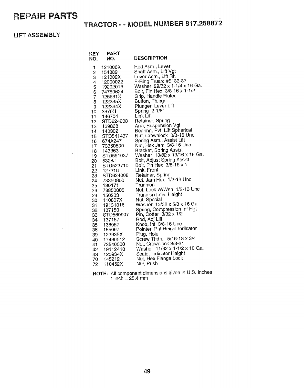
REPABR PARTS
LIFT ASSEMBLY
TRACTOR -- MODEL NUMBER 917.258872
KEY PART
NO. NO, DESCRIPTION
1 121006X
2 154389
3 121002X
4 12000022
5 19292016
6 74780624
7 125631X
8 122365X
9 I22364X
10 2876H
1t 146704
!2 STD624008
13 139868
14 140302
15 STD541437
16 674A247
17 73350600
18 143363
19 STD55!037
20 5328J
21 STD523710
22 127218
23 STD624008
24 7335O8OO
25 13O171
26 7380080O
29 150233
3O 110807X
31 19131016
32 137150
33 STD560907
34 137167
35 138057
38 155097
39 123935X
40 17490512
4I 73540600
42 1911241O
43 123934)(
70 145212
72 I10452X
Rod Asm, Lever
Shaft Asm, Lift Vgt
Lever Asm. Lift Rh
E-Ring Truarc #5133-87
Washer 29/32 x I-1/4 x 16 G&
Bolt, Fin Hex 3/8-16 x I-1/2
Grip, Handle Fluted
Button, Plunger
Plunger, Lever Lift
Spring 2-1/8"
Link Lift
Retainer, Spring
Arm, Suspension Vgt
Bearing, Pvt. Lift Spherical
Nut, CrownIock 3/8-t6 Unc
Spring Asrn, Assist Lift
Nut, Hex Jam 3/8-16 Unc
Bracket, Spring Assist
Washer 13/32 x 13/16 x t6 Ga
Bolt, Adjust Spring Assist
Bolt, Fin Hex 3/8-16 x 1
Link, Front
Retainer, Spring
Nut, ,Jam Hex 1/2-13 Unc
Trunnion
Nut, Lock W/Wsh 1/2-13 Unc
Trunnion Infin, Heigl_t
Nut, Special
Washer 13/32 x 5/8 x 16 Ga,
Spring, Compression Inf Hgt
Pin, Cotter 3/32 x 1/2
Rod, Adj Lift
Knob, inf 3/8-16 Unc
Pointer, Pnt Height Indicator
Plug, Hole
Screw Thdrol 5/16-18 x 3/4
Nut, Crownlock 3/8-24
Washer t 1/32 x 1-1/2 x 10 Ga,.
Scale, Indicator Height
Nut, Hex Flange Lock
Nut, Push
NOTE: All component dimensions given in U .S. inches
1 inch = 25,4 mm
49
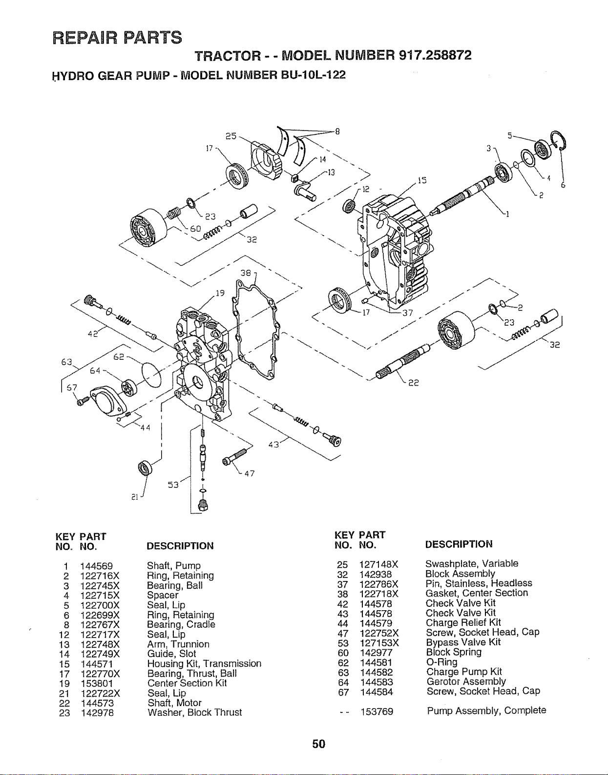
REPAUR PARTS
TRACTOR - - MODEL NUMBER 917.258872
HYDRO GEAR PUIV1P -MODEL NUMBER BU-10L-122
_-. J 3s
44
KEY
NOo
1
2
3
4
5
6
8
12
13
14
15
17
19
21
22
23
PART
NO.
144569
122716X
122745X
122715X
122700X
122699X
122767X
122717X
122748X
122749X
144571
122770X
153801
122722X
144573
142978
DESCRIPTION
Shaft, Pump
Ring, Retaining
Bearing, Bali
Spacer
Seal, Lip
Ring, Retaining
Bearing, Cradle
Seal, Lip
Arm, Trunnion
Guide, Slot
Housing Kit, Transmission
Bearing, Thrust, Ball
Center Section Kit
Seal, Lip
Shaft, Motor
Washer, Block Thrust
KEY PART
NO. NO.
25 127148X
32 142938
37 122786X
38 122718X
42 144578
43 144578
44 144579
47 122752X
53 127153X
60 142977
62 144581
63 144582
64 144583
67 144584
153769
DESCRIPTION
Swashplate, Variable
Btock Assembly
Pin, Stainless, Headless
Gasket, Center Section
Check Valve Kit
Check Valve Kit
Charge Relief Kit
Screw, Socket Head, Cap
Bypass Valve Kit
Block Spring
O-Ring
Charge Pump Kit
Gerotor Assembly
Screw, Socket Head, Cap
Pump Assembly, Complete
5O
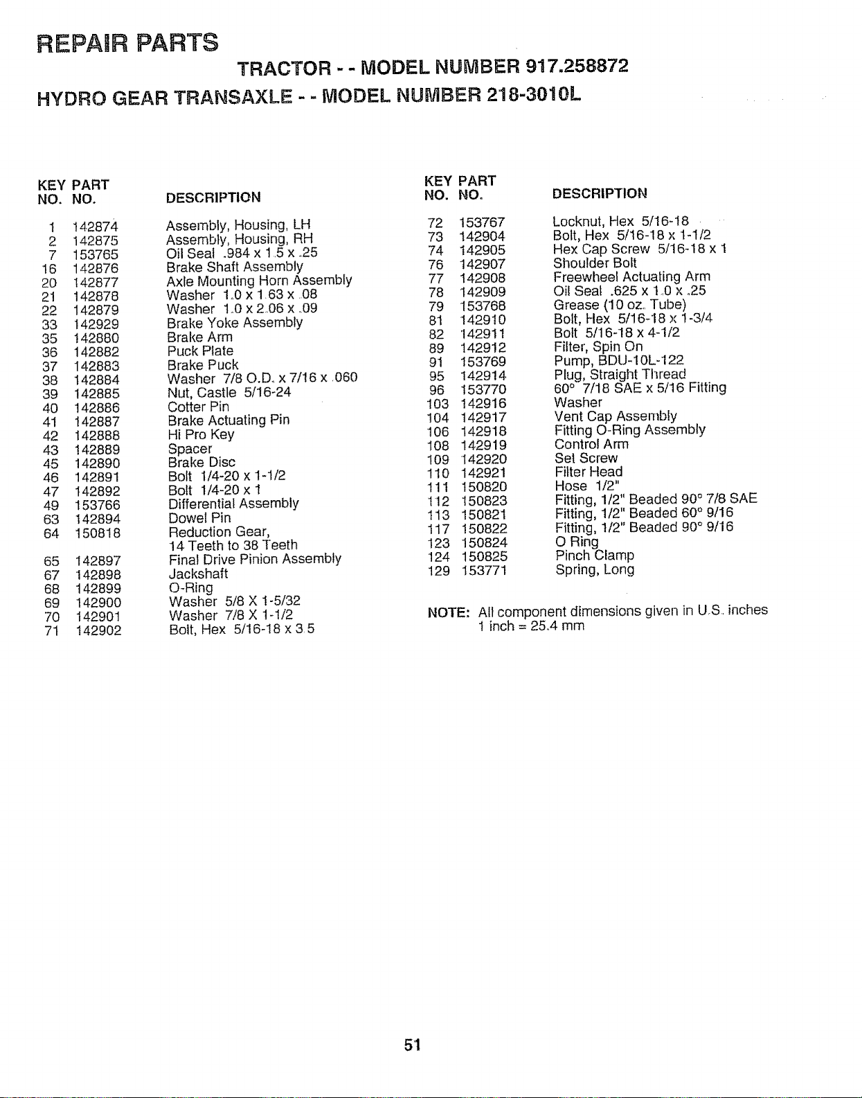
REPAUR PARTS
TRACTOR - - MODEL NUMBER 917.258872
HYDRO GEAR TRANSAXLE - - MODEL NUMBER 2'18-3010L
KEY PART KEY PART
NO. NO. DESCRIPTION NO. NO. DESCRIPTION
I !42874 Assembly, Housing, LH 72 153767
2 142875 Assembly, Housing, RH 73 142904
7 153765 Oil Seal .984x1.5x.25 74 142905
16 142876 Brake Shaft Assembly 76 142907
20 142877 Axle Mounting Horn Assembly 77 142908
21 142878 Washer lo0X 163x 08 78 142909
22 142879 Washer 1o0 x 2,06 x .09 79 '153768
33 I42929 Brake Yoke Assembly 81 142910
35 142880 Brake Arm 82 1429! 1
36 142882 Puck Plate 89 142912
37 142883 Brake Puck 91 153769
38 142884 Washer 7/80.D. x 7/16 x 060 95 142914,
39 142885 Nut, Castle 5/16-24 96 153770
40 142886 Cotter Pin 103 142916
41 142887 Brake Actuating Pin 104 142917
42 142888 Hi Pro Key 106 142918
43 142889 Spacer I08 142919
4.5 142890 Brake Disc 109 142920
46 142891 Bolt 1/4-20 x 1-1/2 110 142921
47 142892 Bolt 1/4-20x 1 111 150820
49 153766 Differential Assembly 112 150823
63 142894 Dowel Pin 113 150821
64 !50818 Reduction Gear, 117 150822
14 Teeth to 38 Teeth 123 150824
65 i42897 Final Drive Pinion Assembly 124 150825
67 142898 Jackshaft 129 153771
68 142899 O-Ring
69 142900 Washer 5/8 X 1-5/32
70 142901 Washer 7/8 X 1-I/2
7t 142902 Bolt, Hex 5/16-18 x 3.5
Locknut, Hex 5/16-18
Bolt, Hex 5/t6-18 x t-1/2
Hex Cap Screw 5/16q8 x 1
Sl_oulder Bolt
Freewheel Actuating Arm
Oil Seat .625 x t ..0x °25
Grease (10 oz. Tube)
Bolt, Flex 5/16-18 x 1-3/4
Bolt 5/16-18 x 4-1/2
Filter, Spin On
Pump, BDU-10L-122
Plug, Straight Tl_read
60 ° 7/18 SAE x 5/16 Fitting
Washer
Vent Cap Assembly
Fitting O-Ring Assembly
Control Arm
Set Screw
Filter Head
Hose 1/2"
Fitting, 1/2" Beaded 90° 7/8 SAE
Fitting, 1/2" Beaded 60° 9/16
Fitting, t/2" Beaded 90° 9/16
O Ring
Pinch Clamp
Spring, Long
NOTE: All component dimensions given in U,S, inches
I inch = 25..4 mm
5'1
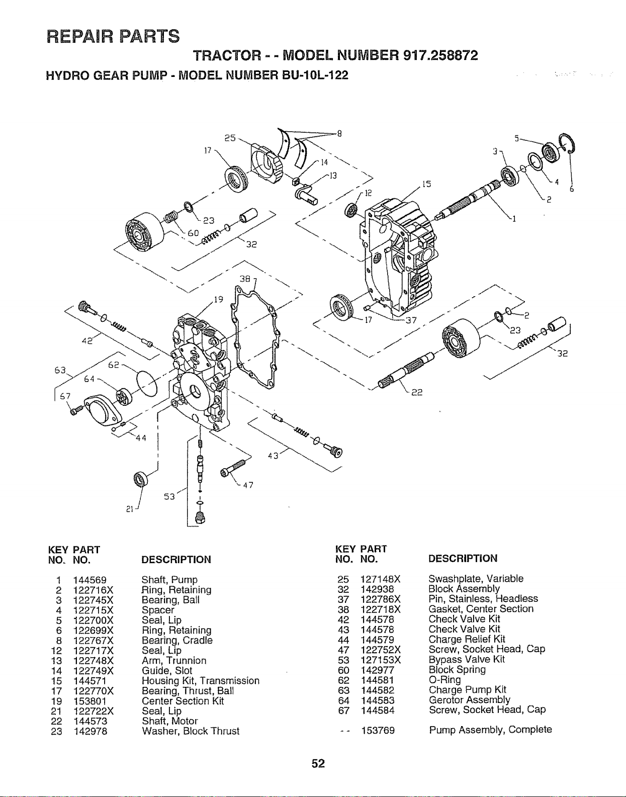
REPAUR PARTS
TRACTOR-- MODEL NUMBER 917.258872
HYDRO GEAR PUMP - MODEL NUMBER BU-10L-122
<
15
22
2_
!
44 I
1.1"
53 I
'-47
KEY PART
NO. NO.
1 144569
2 122716X
3 122745X
4 122715X
5 122700X
6 122699X
8 122767X
12 122717X
13 122748X
14 122749X
15 144571
17 122770X
19 153801
21 122722X
22 144573
23 142978
DESCRIPTION
Shaft, Pump
Ring, Retaining
Bearing, Ball
Spacer
Seal, Lip
Ring, Retaining
Bearing, Cradle
Seal, Lip
Arm, Trunnion
Guide, Slot
Housing Kit, Transmission
Beadng, Thrust, Ball
Center Section Kit
Seal, Lip
Shaft, Motor
Washer, Block Thrust
KEY PART
NO. NO.
25 127148X
32 142938
37 122786X
38 122718X
42 144578
43 144578
44 144579
47 122752X
53 127153X
60 142977
62 144581
63 144582
64 144583
67 144584
153769
DESCRIPTION
Swashplate, Variable
Block Assembly
Pin, Stainless, Headless
Gasket, Center Section
Check Valve Kit
Check Valve Kit
Charge Relief Kit
Screw, Socket Head, Cap
Bypass Valve Kit
Block Spring
O-Ring
Charge Pump Kit
Gerotor Assembly
Screw, Socket Head, Cap
Pump Assembly, Complete
52
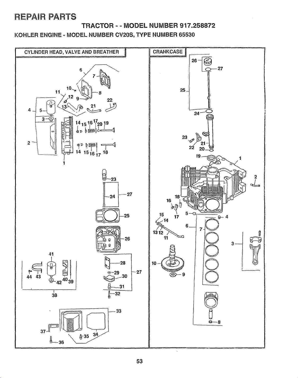
REPABR PARTS
TRACTOR - - MODEL NUMBER 917.258872
KOHLER ENGINE ..,MODEL NUMBER CV20S, TYPE NUMBER 65530
CYLINDER HEAD, VALVE AND BREATHER _
6
22
41
44 43
t
_27
26 -_C)--- 27
25_
2
18
16
©
©
€,--- 8
3_
53
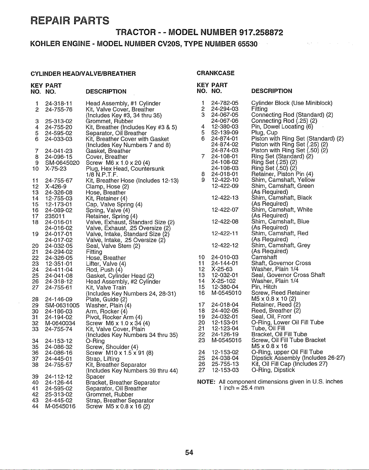
REPAIR PARTS
TRACTOR - - MODEL NUMBER 917.258872
KOHLER ENGINE - MODEL NUMBER CV20S, TYPE NUMBER 65530
CYLINDER HEAD/VALVE/BREATHER
CRANKCASE
KEY PART KEY PART
NO, NO. DESCRIPTION NO, NO. DESCRIPTION
24-318-11
24-755-76
1
2
3 25-313-02
4 24-755-20
5 24-595-02
6 24-033-03
7 24-041-23
8 24-096-t5
9 SM-0645020
10 X-75-23
11 24-755-67
12 X-426-9
13 24-326-08
14 12-755-03
15 12-173-01
16 24-089_02
17 235011
18 24-016-01
24-016-02
19 24-017-01
24-017-02
20 24-032-05
21 24-294_02
22 24-326-05
23 12-351-01
24 24-411-04
25 24-041-08
26 24-318-12
27 24-755-61
28 24-146-09
29 SM-0631005
3O 24-186-03
31 24_194-02
32 M-0640034
33 24-755-74
34 24-t53-12
35 24-086-32
36 24-086-16
37 24-445-01
38 24-755-57
Head Assembly, #1 Cylinder 1
Kit, Valve Cover, Breather 2
(Includes Key #3, 34 thru 35) 3
Grommet, Rubber
Kit, Breather (Includes Key #3 & 5) 4
Separator, Oil Breather 5
Kit, Breather Cover with Gasket 6
(Includes Key Numbers 7 and 8)
Gasket, Breather
Cover, Breather 7
Screw M6 x 1.0 x 20 (4)
Plug, Hex Head, Countersunk
I/8 NoP.T.F. 8
Kit, Breather Hose (Includes 12-13) 9
Clamp, Hose (2)
Hose, Breather
Kit, Retainer (4)
Cap, Valve Spring (4)
Spring, Valve (4)
Retainer, Spring (4)
Valve, Exhaust, Standard Size (2)
Valve, Exhaust, .25 Oversize (2)
Valve, Intake, Standard Size (2)
Valve, Intake, 25 Oversize (2)
Seal, Valve Stem (2)
Fitting
Hose, Breather 10
Lifter', Valve (4) 11
Rod, Push (4) 12
Gasket, Cylinder Head (2) 13
Head Assembly, #2 Cylinder 14
Kit, Valve Train 15
(Includes Key Numbers 24, 28-31) 16
Plate, Guide (2)
Washer, Plain (4) 17
Arm, Rocker (4) 18
Pivot, Rocker Arm (4) 19
Screw M6 x 1.0 x 34 (4) 20
Kit, Valve Cover, Plain 21
(Includes Key Numbers 34 thru 35) 22
O-Ring 23
Screw, Shoulder (4)
Screw M10 x 1,.5x 91 (8) 24
Strap, Lifting 25
Kit, Breather Separator 26
(Includes Key Numbers 39 thru 44) 27
Spacer'
Bracket, Breather Separator
Separator, Oil Breather
Grommet, Rubber
Strap, Breather Separator'
Screw M5 x 0.8 x 16 (2)
39 24-112-12
40 24-126-44
41 24-595_02
42 25-3!3-02
43 24-445-02
44 M-0545016
24-782-05
24-294-03
24-067-05
24-067-06
!2-380-03
52-139-09
24-874-01
24-874-02
24-874=03
24-108-01
24-108-02
24-108-03
24-018-01
12-422-10
12-422-09
12-422-13
12-422_07
! 2-422-08
12-422-11
12-422-12
24-01 O-03
24-144-01
X-25-63
12-032-01
X-25-102
12-380-04
M-0545010
24-018_04
24-402-05
24-032-01
12-153-01
12-123-04
24-126-19
M-0545016
12-153-02
24-038-04
25-755-13
12-153-03
Cylinder Block (Use Miniblock)
Fitting
Connecting Rod (Standard) (2)
Connecting Rod (.25) (2)
Pin, Dowet Locating (6)
Plug, Cup
Piston with Ring Set (Standard) (2)
Piston with Ring Set (_25) (2)
Piston with Ring Set (.50) (2)
Ring Set (Standard) (2)
Ring Set (..25) (2)
Ring Set (.50) (2)
Retainer-, Piston Pin (4)
Shim, Camshaft, Yellow
Shim, Camshaft, Green
(As Required)
Shim, Camshaft, Black
(As Required)
Shim, Camshaft, White
(As Required)
Shim, Camshaft, Blue
(As Required)
Shim, Camshaft, Red
(As Required)
Shim, Camshaft, Grey
(As Required)
Camshaft
Shaft, Governor Cross
Washer, Plain 1/4
Seal, Governor Cross Shaft
Washer, Plain 1/4
Pin, Hitch
Screw, Reed Retainer
M5 x 0..8 x 10 (2)
Retainer, Reed (2)
Reed, Breather (2)
Seal, Oil, Front
O-Ring, Lower Oil Fill Tube
Tube, Oil Fill
Bracket, Oil Fill Tube
Screw, Oil Fill Tube Bracket
M5 x 08 x 16
O-Ring, upper Oil Fill Tube
Dipstick Assembly (includes 26-27)
Kit, Oil Fill Cap (Includes 27)
O-Ring, Dipstick
NOTE: All component dimensions given in U.S. inches
I inch = 25.4 mm
54
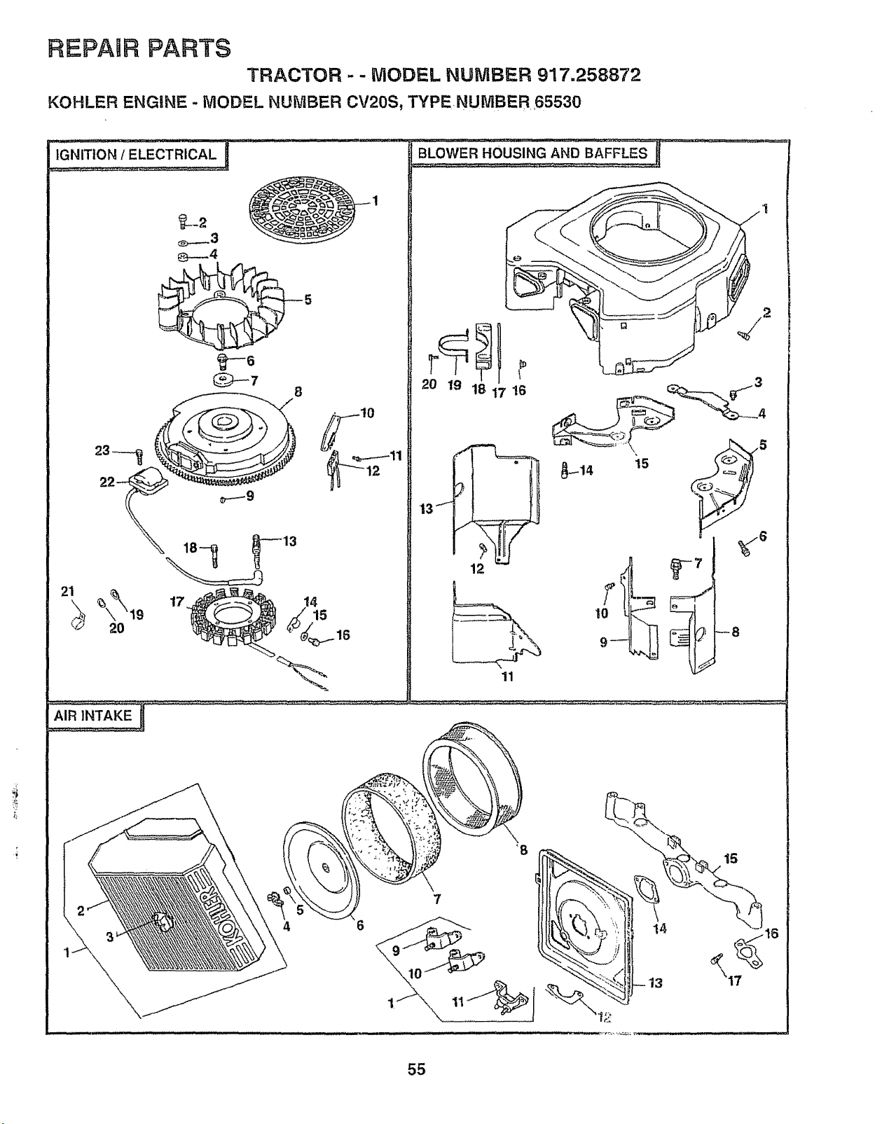
REPAIR PARTS
TRACTOR - - MODEL NUMBER 917.258872
KOHLER ENGINE - MODEL NUMBER CV20S, TYPE NUNIBER 65530
U
IGNITION / ELECTRICAL
8
. 10
21
17
15
20 19 18 17 16
t3J
12
11
_8
4 6
55
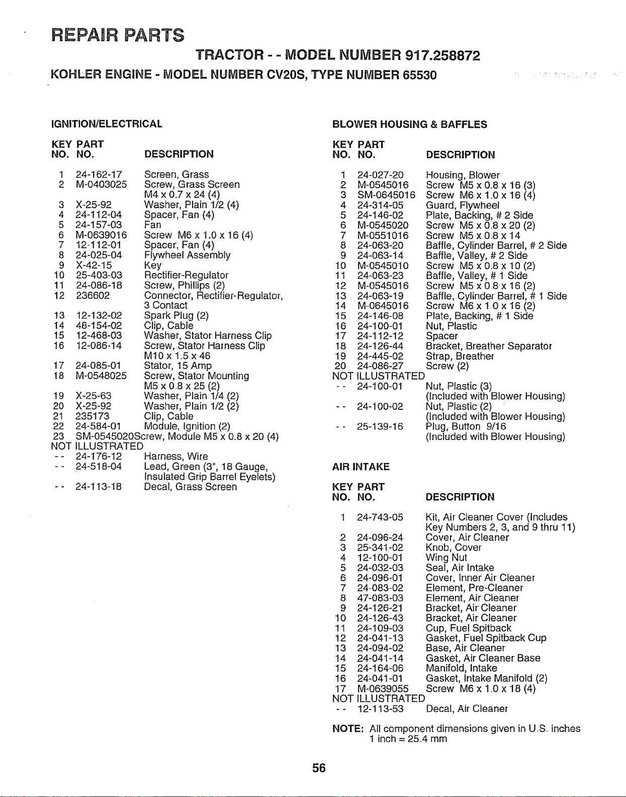
REPABRPARTS
TRACTOR-- MODEL NUMBER 917.258872
KOHLER ENGINE - MODEL NUMBER CV20S, TYPE NUMBER 65530
IGNITION!ELECTRICAL
BLOWER HOUSING & BAFFLES
KEY PART KEY PART
NO. NO. DESCRIPTION NO, NO. DESCRIPTION
1 24-162-17 Screen, Grass 1 24-027-20
2 M-0403025 Screw, Grass Screen 2 M-0545016
M4 x 0.7 x 24 (4) 3 SM-0645016
3 X-25-92 Washer, Plain 1/2 (4) 4 24-314-05
4 24-112-04 Spacer, Fan (4) 5 24-146-02
5 24-157-03 Fan 8 M-0545020
6 M-0639016 Screw M8 x 1.0 x 18 (4) 7 M-0551016
7 12_112-01 Spacer, Fan (4) 8 24-083-20
8 24-025-04 Flywheel Assernbfy 9 24-083_14
9 X-42-15 Key 10 M-0545010
10 25-403-03 Rectifier-Regulator 11 24-063-23
11 24-086-18 Screw, Phillips (2) t2 M-0545018
12 236602 Connector, Rectifier-Regulator, 13 24-063-19
3 Contact 14 M-0645016
13 12-132-02 Spark Plug (2) 15 24-148-08
14 48-154-02 Clip, Cable 16 24-100-01
15 12-468-03 Washer, Stator Harness Clip 17 24-112-12
16 !2-086-14 Screw, Stator Harness Clip 18 24-126-44
MI0 x 1.5 x 46 19 24-445-02
17 24-085-01 Stator, 15 Amp 20 24-086-27
18 M-0548025 Screw, Stator Mounting NOT
M5 x 0 8 x 25 (2) - -
19 X-25-63 Washer, Plain 1/4 (2)
20 X-25-92 Washer, Plain 1/2 (2) --
21 235173 Clip, Cable
22 24-584-01 Module, Ignition (2) --
23 SM-0545020Screw, Module M5 x 0.8 x 20 (4)
NOT ILLUSTRATED
-- 24-178-I2 Harness, Wire
24-518-04 Lead, Green (3", 18 Gauge,
Insulated Grip Barrel Eyelets)
24-113-18 Decal, Grass Screen
Housing, Blower'
Screw M5 x 0.8 x 16 (3)
Screw M6 x 1_0 x 16 (4)
Guard, Flywheel
Plate, Backing, # 2 Side
Screw M5 x 0.8 x 20 (2)
Screw M5 x 0,8 x 14
Baffle, Cylinder Barrel, # 2 Side
Baffle, Valley, # 2 Side
Screw M5 x 0.8 x 10 (2)
Baffle, Valley, # 1 Side
Screw M5 x 0.8 x 16 (2)
Baffle, Cylinder' Barrel, # 1 Side
Screw M6x10x16(2)
Plate, Backing, # 1 Side
Nut, Plastic
Spacer
Bracket, Breather Separator
Strap, Breather
Screw (2)
ILLUSTRATED
24-100-01 Nut, Plastic (3)
(Included with Blower Housing)
24-100-02 Nut, Plastic (2)
(Included with Blower Housing)
25-139-16 Plug, Button 9/16
(Included with Blower' Housing)
AIR INTAKE
KEY PART
NO, NO, DESCRIPTION
24-743-O5
2 24-096-24
3 25-341-02
4 12-100-01
5 24-032-03
6 24-096-0!
7 24_083-02
8 47-083-03
9 24-128-21
10 24-126-43
11 24-109-03
12 24-041-13
13 24-094-02
14 24-041-14
15 24_164_06
16 24-041-01
17 M-0639055
NOT
Kit, Air Cleaner Cover (Includes
Key Numbers 2, 3, and 9 thru 11)
Cover, Air Cleaner
Knob, Cover
Wing Nut
Seal, Air intake
Cover-, Inner Air Cleaner
Element, Pre-Cleaner
Element, Air Cleaner
Bracket, Air Cleaner
Bracket, Air Cleaner'
Cup, Fuel Spitback
Gasket, Fuel Spitback Cup
Base, Air Cleaner
Gasket, Air' Cleaner' Base
Manifold, Intake
Gasket, Intake Manifold (2)
Screw M6 x 1.0 x 18 (4)
ILLUSTRATED
12-113-53 Decal, Air Cleaner
NOTE: All component dimensions given in US.. inches
1 inch = 25.,4 mm
56
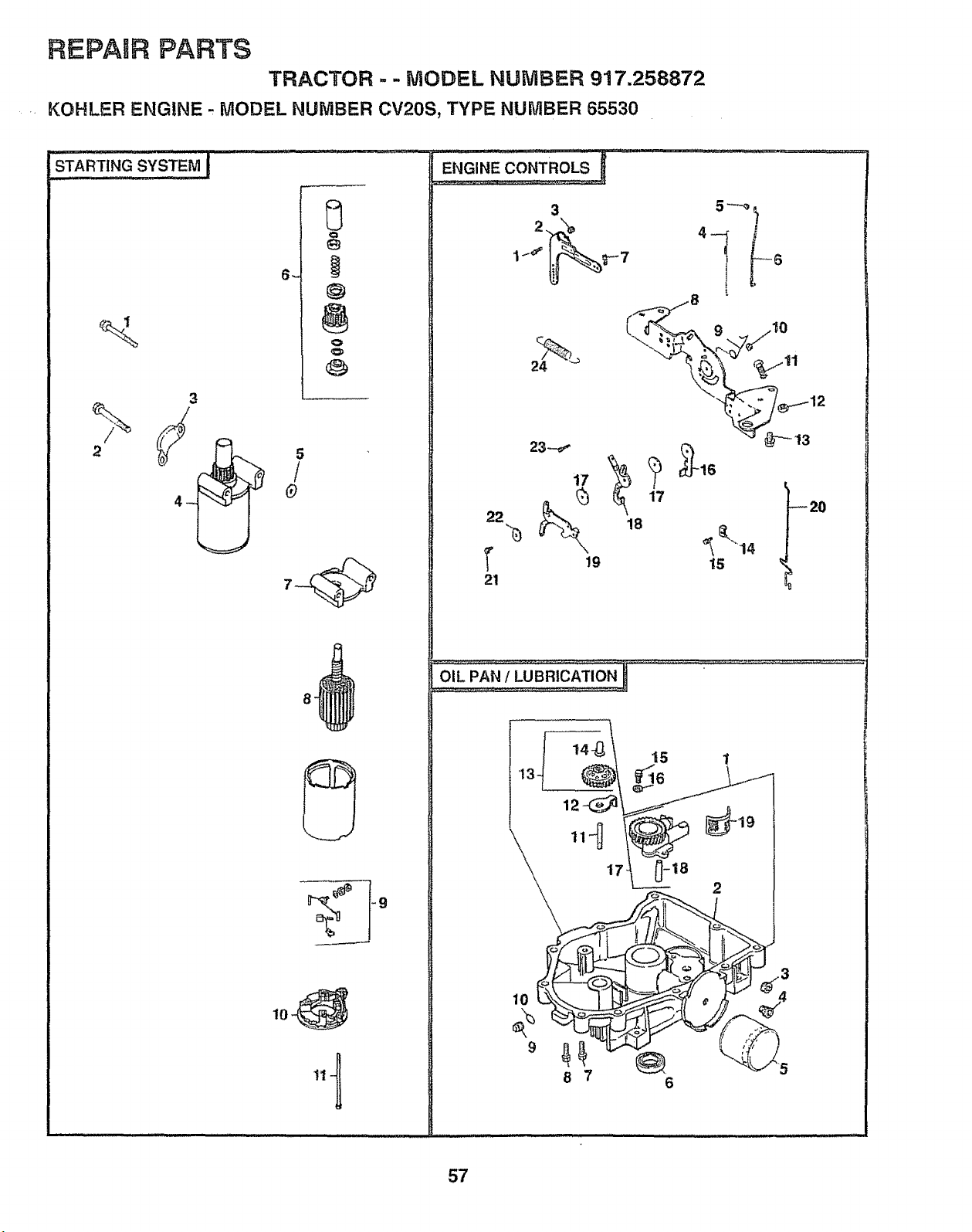
REPAIR PARTS
TRACTOR - - MODEL NUMBER 917.258872
KOHLER ENGINE , MODEL NUMBER CV20S, TYPE NUMBER 65530
STARTINGS'CSTEMJ
2
Q
@
3
8.
ENGINE CONTROLS
3 5"-_)
2 N 4
17 _ 20
22 !8
r ,, I,%
21
13 _6
2
8 7
57
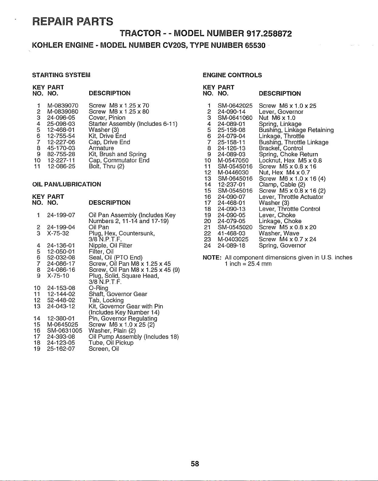
REPAIR PARTS
TRACTOR -- MODEL NUMBER 917.258872
KOHLER ENGIN_ = - MODEL NUMBER CV20S, TVPF: NUMBER 65530 •
STARTING SYSTEM ENGINE CONTROLS
KEY PART KEY PART
NO. NO. DESCRIPTION NO. NO.
t M-0839070 Screw M8 x 125 x 70
2 M-0839080 Screw M8 x 125 x 80
3 24-096-05 Cover, Pinion
4 25-098-03 Starter Assembly (Includes 6-11)
5 12-468-01 Washer (3)
6 12-755-54 Kit, Drive End
7 12-227-06 Cap, Drive End
8 45-170-03 Armature
9 82-755-28 Kit, Brush and Spring
10 12-227-11 Cap, Commutator End
11 12-086-25 Bolt, Thru (2)
OIL PAN/LUBRICATION
DESCRIPTION
KEY PART
NO. NO.
24-199-07
2 24q 99-04
3 X-75-32
4 24-136-01
5 12-050-01
6 52-032-08
7 24-086-17
8 24-086-16
9 X-75-10
I0 24-153-08
11 12-144-02
12 52-448-02
!3 24-043-12
Oil Pan Assembly (Includes Key
Numbers 2, 11-14 and 17-19)
Oil Pan
Plug, Hex, Countersunk,
3/8 N_P.T..F.
Nipple, Oi! Filter
Filter, Oil
Seal, Oil (PTO End)
Screw, Oil Pan M8 x 125 x 45
Screw, Oil Pan M8 x 1_25 x 45 (9)
Plug, Solid, Square Head,
3/8 N..P,T.F.
O-Ring
Shaft, Governor Gear
Tab, Locking
Kit, Governor Gear with Pin
(Includes Key Number 14)
Pin, Governor Regulating
Screw M6 x 1.0 x 25 (2)
Washer, Plain (2)
Oil Pump Assembly (includes 18)
Tube, Oil Pickup
Screen, Oil
14 12-380-01
15 M-0645025
16 SM-0631005
17 24-393-08
18 24-123-05
19 25-162-07
DESCRIPTION
1 SM-0642025 Screw M6x 1_0x25
2 24o090-14 Lever,. Governor
3 SM-0641060 Nut M6x 1.0
4 24-089-01 Spring, Linkage
5 25-158-08 Bushing, Linkage Retaining
6 24-079-04 Linkage, Throttle
7 25-158q I Bushing, Throttle Linkage
8 24-126-13 Bracket, Control
9 24-089-03 Spring, Choke Return
10 M-0547050 Locknut, Hex M5 x 0_8
11 SM-0545016 Screw M5x0,Sx16
12 M-0446030 Nut, Hex M4 x 0.7
13 SM-0645016 Screw M6 x 1.0 x16 (4)
14 12-237-01 Clamp, Cable (2)
15 SM-05450!6 Screw M5 xQB x16 (2)
16 24-090-07 Lever, Throttle Actuator
17 24-468-01 Washer (3)
18 24-090-13 Lever, Throttle Control
19 24-090-05 Lever', Choke
20 24-079-05 Linkage, Choke
21 SM-0545020 Screw M5 x08 x20
22 41-468_03 Washer, Wave
23 M-0403025 Screw M4 x 0..7 x 24
24 24-089-18 Spring, Governor'
NOTE: All component dimensions given in US. inches
1 inch = 25..4 mm
58
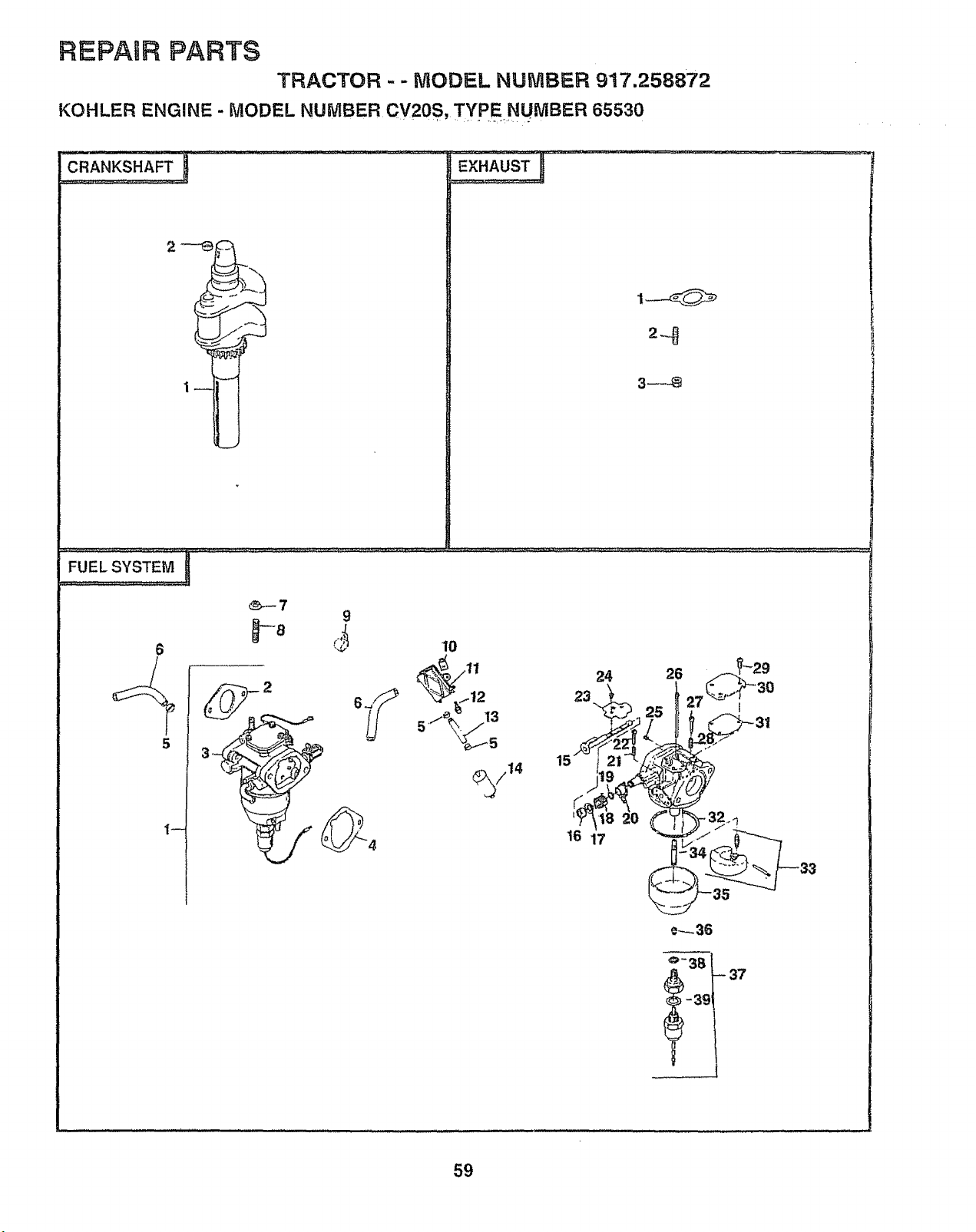
REPAIR PARTS
TRACTOR - - MODEL NUMBER 917.258872
KOHLER ENGINE - MODEL NUMBER Cv20s, TYPENUMBER 65530
FUEL SYSTEM !
24 26
23
16 17
e-_36
59
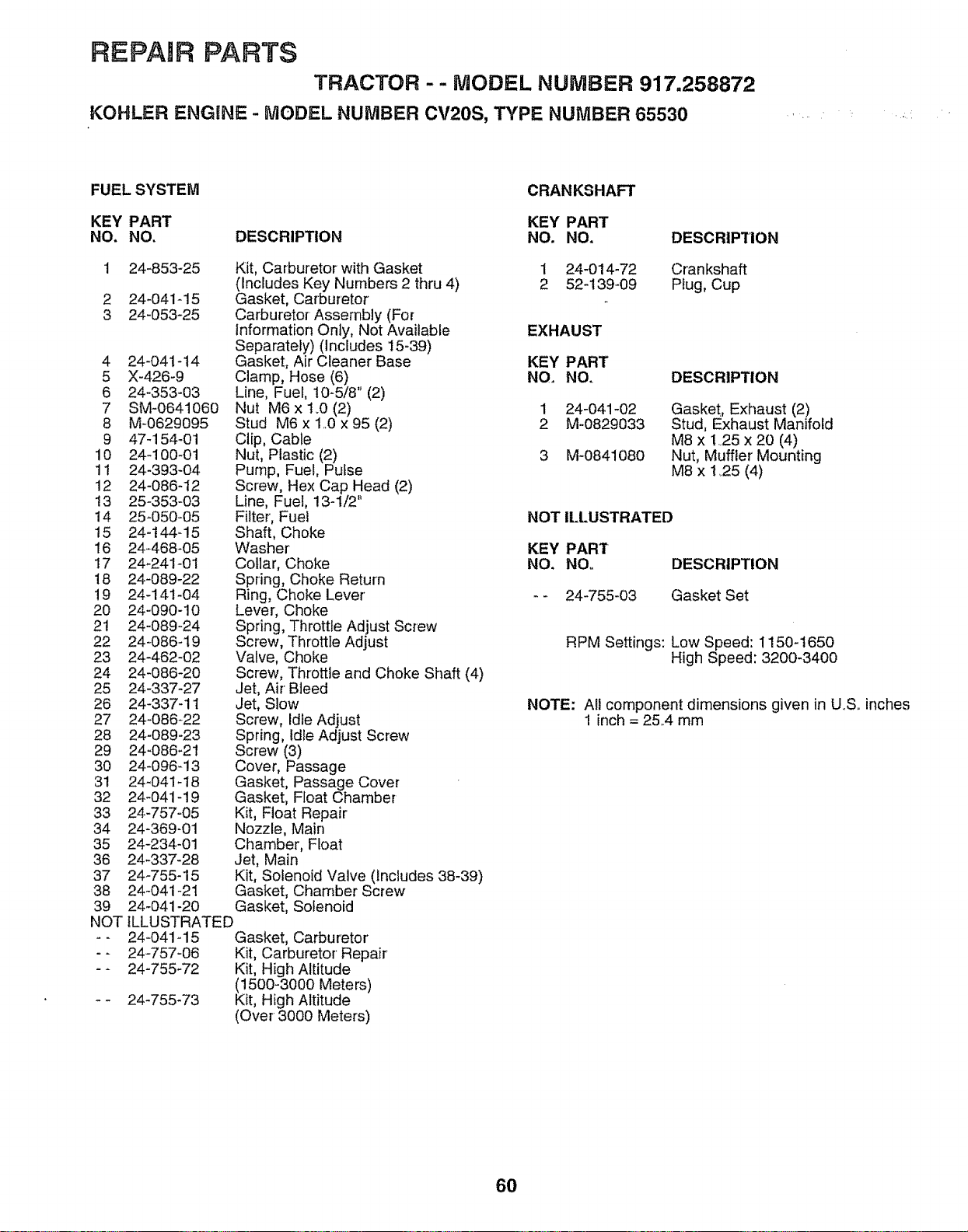
REPAnR PARTS
TRACTOR - - MODEL NUMBER 917,258872
KOHLER ENGINE - MODEL NUMBER CV20S, TYPE NUMBER 65530
FUEL SYSTEM
KEY PART
NO. NO. DESCRIPTION
1 24-853-25
2 24-041-15
3 24-053-25
4 24-041-14
5 X-426-9
6 24-353-03
7 SM-0641060
8 M-0629095
9 47-154-01
10 24_100-01
11 24-393-04
12 24-086-12
13 25-353-O3
14 25-050-05
15 24-144-15
16 24-468-05
17 24-241-01
18 24-089-22
19 24-141-04
20 24-090-10
21 24-089-24
22 24-086_19
23 24-462-02
24 24-086-20
25 24-337-27
26 24-337-11
27 24-086-22
28 24-089-23
29 24-086-21
30 24-096-13
31 24-041-18
32 24-041-19
33 24-757-05
34 24-369-01
35 24-234-01
36 24-337-28
37 24_755-15
38 24-041-21
39 24-041-20
NOT
. =
Kit, Carburetor with Gasket
(Includes Key Numbers 2 thru 4)
Gasket, Carburetor
Carburetor Assembly (For
Information Only, Not Available
Separately) (Includes 15-39)
Gasket, Air Cleaner Base
Clamp, Hose (6)
Line, Fuel, 10-5/8" (2)
Nut M6 x t.0 (2)
Stud M6 x 1.,0 x 95 (2)
Clip, Cable
Nut, Plastic (2)
Pump, Fuel, Pulse
Screw, Hex Cap Head (2)
Line, Fuel, 13-1/2
Filter, Fuet
Shaft, Choke
Washer'
Collar, Choke
Spring, Choke Return
Ring, Choke Lever'
Lever, Choke
Spring, Throttle Adjust Screw
Screw, Throttle Adjust
Valve, Choke
Screw, Throttle and Choke Shaft (4)
Jet, Air Bleed
Jet, Slow
Screw, Idle Adjust
Spring, Idle Adjust Screw
Screw (3)
Cover, Passage
Gasket, Passage Cover
Gasket, Float Chamber
Kit, Float Repair
Nozzle, Main
Chamber, Float
Jet, Main
Kit, Solenoid Valve (includes 38-39)
Gasket, Chamber Screw
Gasket, Solenoid
ILLUSTRATED
24-041-15 Gasket, Carburetor'
24-757-06 Kit, Carburetor Repair
24-755_72 Kit, High Altitude
(1500-3000 Meters)
24-755-73 Kit, High Altitude
(Over 3000 Meters)
CRANKSHAFT
KEY PART
NO, NO.
1 24-014-72
2 52-139-09
DESCRIPTION
Crankshaft
Plug, Cup
EXHAUST
KEY PART
NO. NO.
1 24-041-02
2 M-0829033
3 M_0841080
DESCRIPTION
Gasket, Exhaust (2)
Stud, Exhaust Manifold
M8 x 1.,25 x 20 (4)
Nut, Muffler Mounting
M8 x 1_25(4)
NOT ILLUSTRATED
KEY PART
NO. NO. DESCRIPTION
-- 24-755-03 Gasket Set
RPM Settings: Low Speed: 1150-t650
High Speed: 3200-3400
NOTE: All component dimensions given in U,S,. inches
1 inch = 25,4 mm
60

SERVUCE NOTES
61

SERVICE NOTES
62

SUGGESTED GUHDE FOR SUGHTnNGSLOPES FOR SAFE OPERATnON_
-*.,,.,,,,
SIGHTING
GUIDE
ONLY RIDE UP AND DOWN HILL,
NOT ACROSS HiLL
SIGHT AND HOLD THIS LEVEL WITH
SKY LiNE OR TREE.
Operate your Tractor up and down the face of slopes (not
greater than 15°), never across the face. Make turns gradu-
ally to prevent tipping or loss of control. Exercise extreme
caution when changing direction on slopes.
OWNE '
UAL
MODEL NO=
917.258872
iF YOU NEED
REPAIR SERVICE
OR PARTS:
FOR REPAIR SERVICE, CALL
THIS TOLL FREE NUMBER:
1-800-4-REPAIR
(1-800-473-7247)
FOR REPLACEMENT PARTS
INFORMATION AND
ORDERING, CALL THIS
TOLL FREE NUMBER:
1-800-FON-PART
(1-800-366-7278)
FOR CONSUMER ASSISTANCE
HOT LINE, CALL THIS
TOLL FREE NUMBER:
1-800-659-5917
®
!8.5 HP TWiN CYLINDER
ELECTRIC START
46" MOWER
HYDROSTATIC (AUTOMATIC)
GARDEN TRACTOR
Each tractor has its own model number. Each engine has
its own model number.
The model number for your tractor wil_ be found on the
model plate located under the seat.
The model number' for your engine will be found on the
blower housing of the engine.
All parts listed herein may be ordered from any Sears,
Roebuck and Co.. Service Center/Department and most Re-
tail Stores.,
\
WHEN ORDERING REPAIR PARTS, ALWAYS GIVE, THE
FOLLOWING INFORMATION:
• PRODUCT - TRACTOR
° MODEL NUMBER =917.258872
° ENGINE MODEL NO. - CV20S-PS65530
,, PART NUMBER
o PART DESCRIPTION
Your Sears merchandise has added value when you
consider Sears has service units nationwide staffed with
Sears trained technicians.., professional technicians
specifically trained to insure that we meet our pledge to
you, we service what we sell_
161662 08_12_97 KFSW Printed in U.S.A_


