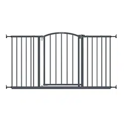
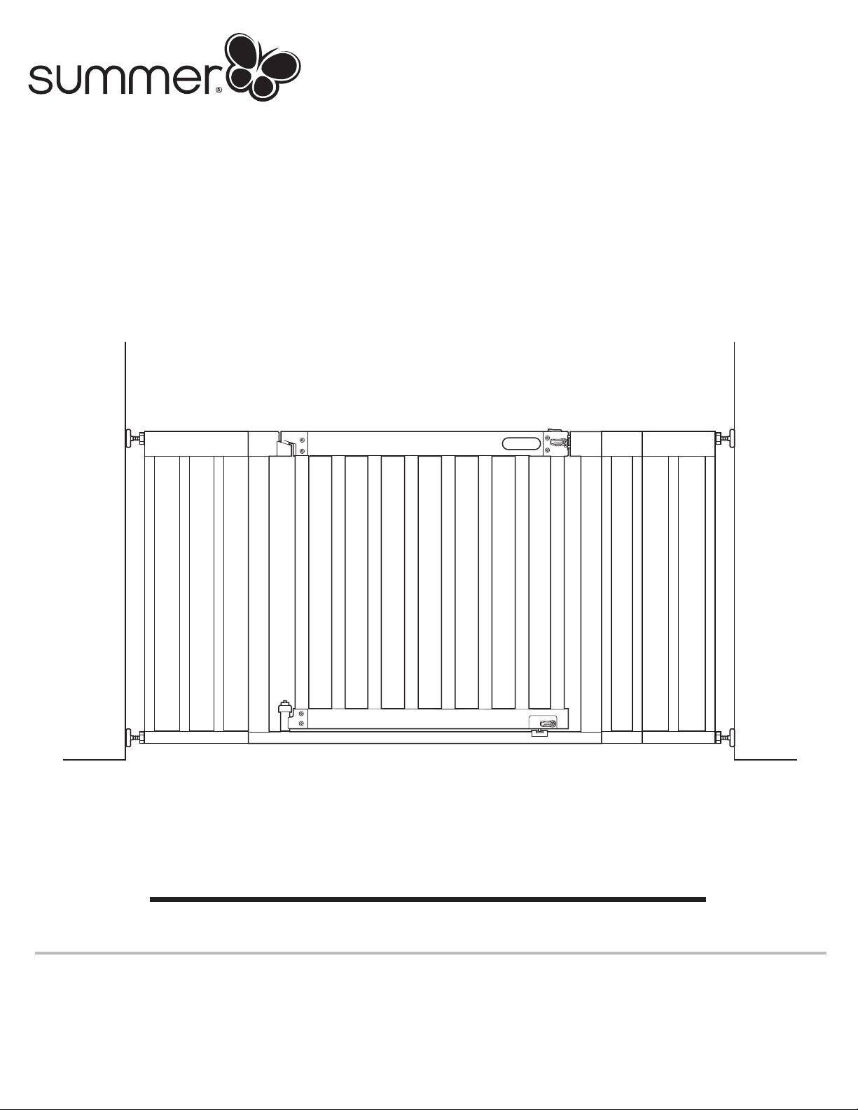
West End
™
Safety Gate
INSTRUCTION MANUAL
Please read the following instructions carefully.
Keep this instruction manual and save for future reference.
Tools required: Phillips head screwdriver, drill (for top of stair installation),
and pencil (not included), wrench (included).
For use with children from 6 - 24 months.
Keep small parts away from children.
Adult assembly required.
Fits openings from 36" - 60" wide.
27950
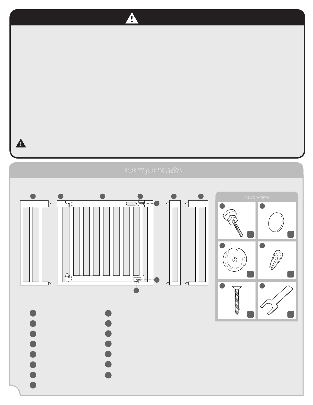
components
Gate Door
Gate Frame
A
B
Short Extension Frame
Medium Extension Frame
C
D
Top Latch
Long Extension Frame
E
H
Adhesive Mounting Pads (4)
Tension Bolts with Tension Nuts (4)
I
Wall Cups (4)
J
K
Wall Anchors (4)
L
Lower Door Stopper
O
Upper Door Stopper
Lower Latch
F
G
Screws (4)
M
Wrench
N
2
hardware
I
x4 x4
J
K L
M N
x4 x4
x1x4
C D
B
E
A
F
H
O
G
Children have died or been seriously injured when gates are not securely installed.
• Always install and use gate as directed, using all required parts. • Install according to manufacturer’s
instructions.
• STOP using a gate when a child can climb over or dislodge the gate.
• Use only with the locking/latching mechanism securely engaged.
• To prevent falls, never use at top of stairs without wall mounting cups and door stoppers.
• NEVER use a gate to keep child away from pool.
• NEVER leave child unattended.
• ALWAYS close and lock the gate behind you.
• This product will not necessarily prevent all accidents. Proper adult supervision is required at all times.
• Do not use if any components are missing or damaged.
• Adult assembly required. Exercise care when unpacking and assembling product.
IMPORTANT – Read the instructions carefully before use and keep them for future reference.
CAUTION KEEP SMALL PARTS OUT OF CHILD’S REACH.
WARNING
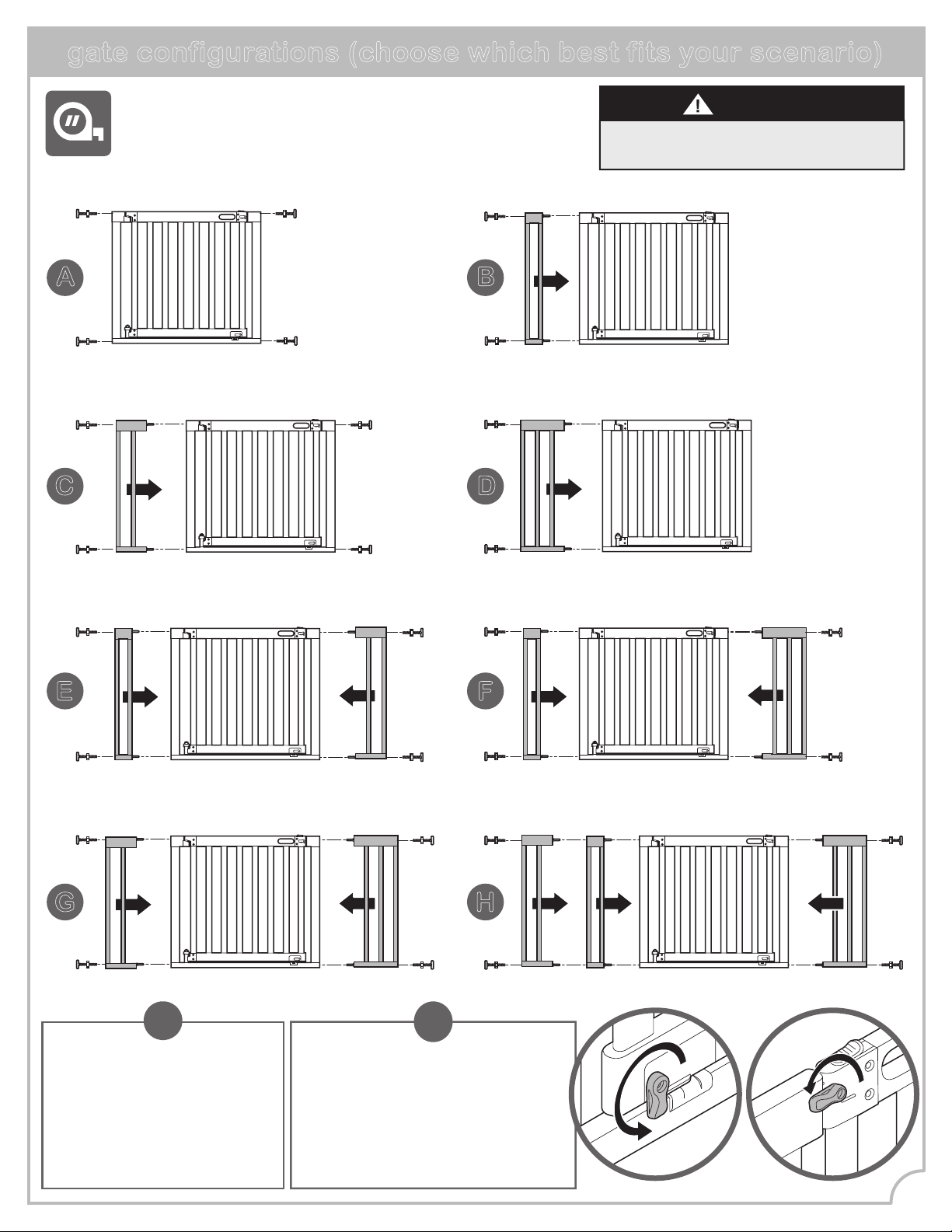
gate configurations (choose which best fits your scenario)
Measure the width of the opening where you intend to install the
gate. Refer to the following illustrations to determine the correct
installation configuration. Baseboard molding may change which
configuration is appropriate.
A B
C D
E
G H
(36 in. - 39 in.) without extension (40 in. - 43 in.) with short extension
(43 in. - 46 in.) with medium extension (46 in. - 49 in.) with one long extension
NEVER install three extension frames
on the same side of the gate.
WARNING
!
Note: This instruction book
illustrates installation of gate
configuration H. If choosing gate
configuration A, skip ahead to step
2. Otherwise, follow step 1 using
the appropriate extension frames
that best fit your scenario.
!
Important: Gate includes door
stoppers (parts O and H) which
prevents the gate from swinging open
in one direction. When installing the
gate at the top of stairs, be sure that
the door stops are engaged on the
opposite side of the stairs so the gate
door cannot open over the stairs.
3
F
(46.75 in. - 50 in.) with short and the medium extensions (49.75 in. - 53 in.) with short and the long extensions
(52.75 in. - 56 in.) with both short and the long extensions (56.75 in.- 60 in.) with short, medium, and long extensions
4
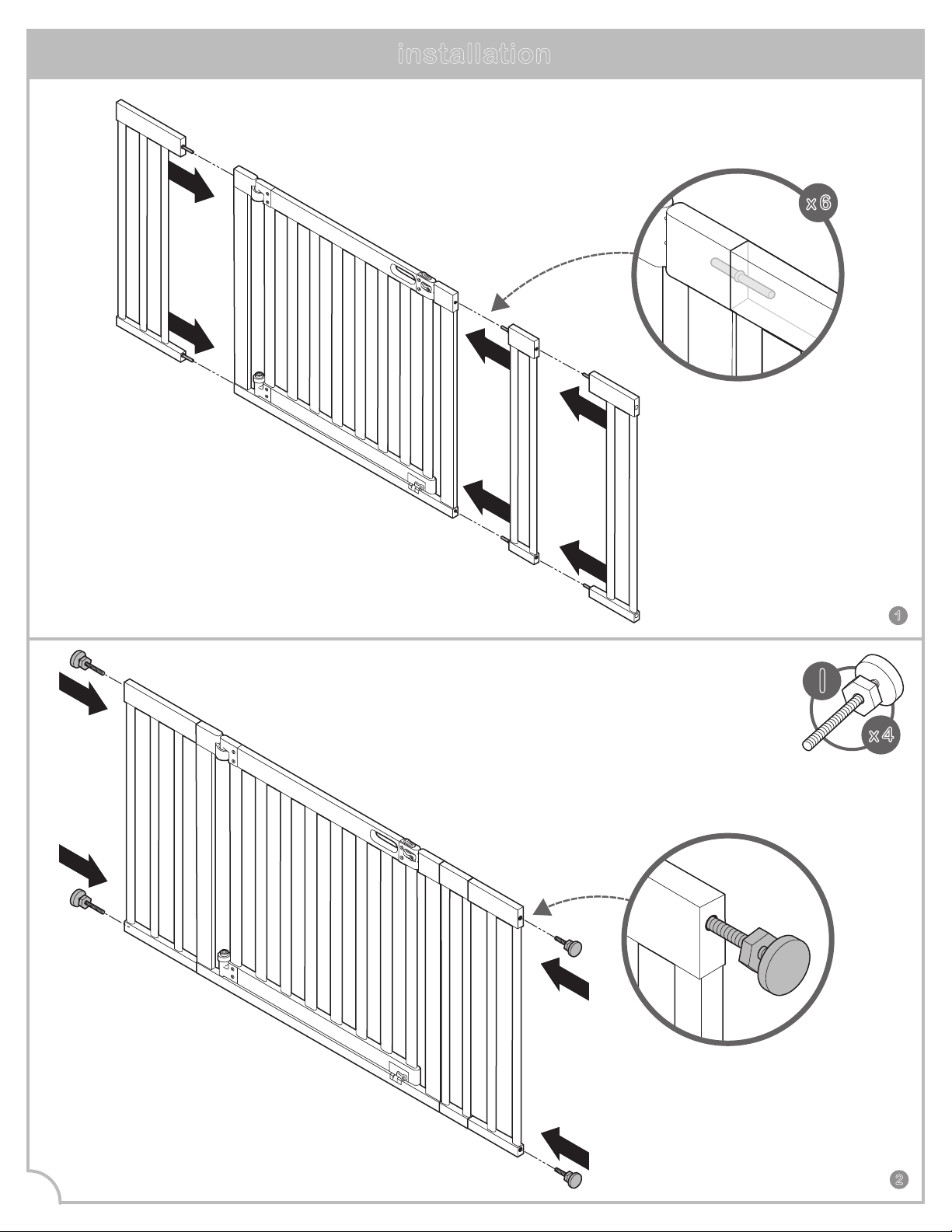
installation
2
Slide tension bolts
into upper and lower holes
on both sides of
extension frames
(or gate frame if no extensions
are being used).
I
x 4
1
x 6
Connect the extension
frames to the gate frame by
inserting the extension pins into the holes
in the extension frame, or into the gate frame
(if extensions are not being used).
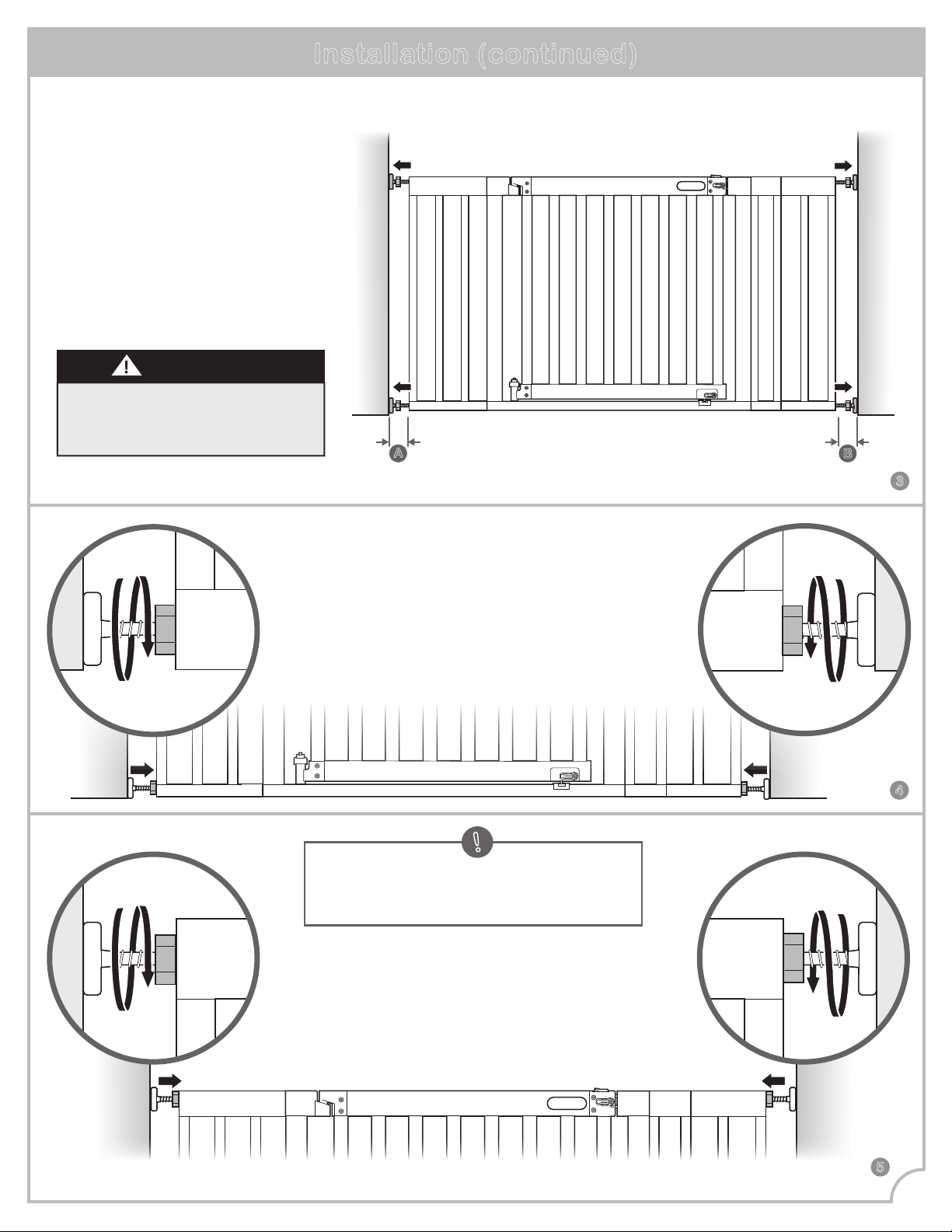
Installation (continued)
Check locations A and B. The
distance between the gate and the
wall should never exceed 2.75”.
IMPORTANT
Use the tension nuts
to tighten both of the
bottom tension bolts.
4
3
5
Use the tension nuts
to tighten both of the
top tension bolts.
A
B
tighten!
tighten!
tighten!
tighten!
5
Note: If mounting at top of stairs, proceed to
step 6. Otherwise, follow the directions in step
14 to tighten the tension nuts.
!
Stand the gate in the
center of the opening.
Make sure the bottom of
the gate is completely flush
to the floor. Slide tension
bolts out until they
contact the door frame
or wall on both sides.
7
6
6
With a pencil, trace
the entire outline
of each tension bolt
directly onto the wall.
Loosen the
lower and upper
tension nuts and
remove gate.
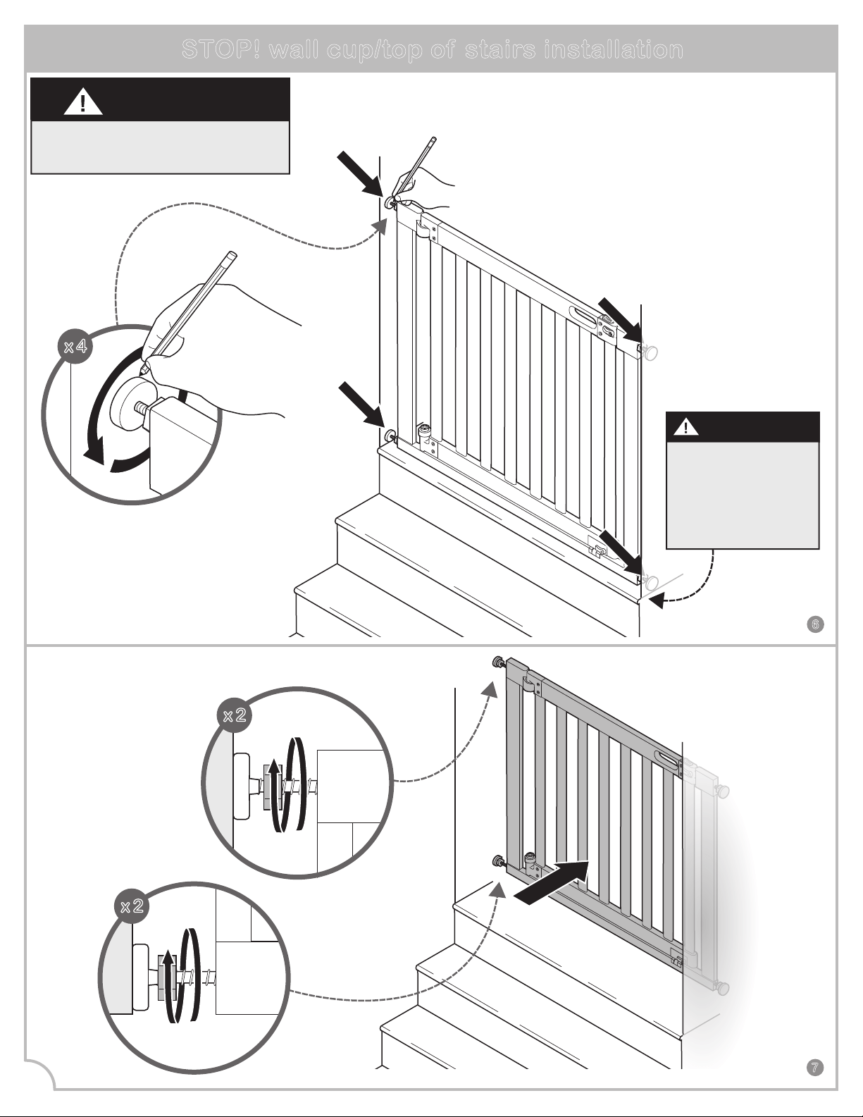
STOP! wall cup/top of stairs installation
WARNING
For use at top of stairs, wall cup
installation is MANDATORY.
Follow these wall cup installation instructions when using gate at TOP OF
STAIRS (MANDATORY), or if using wall cups for a standard opening
(optional). If opting not to use wall cups for a standard opening,
skip ahead to step 14.
x 4
loosen!
loosen!
x 2
x 2
At the top of the
landing, position the
gate a minimum of
3-6 inches (8-15cm)
away from the top
step.
IMPORTANT
8
x 4
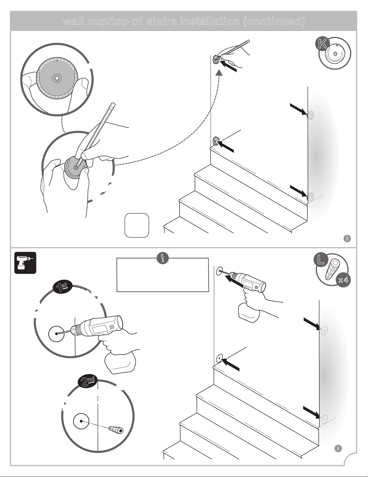
Mark drill
holes with a
pencil through
the center
of each wall cup.
Mark drill
holes with a
pencil through
the center
of each wall cup.
x4
Place a wall cup over
the center of each circular
outline on the wall.
Place a wall cup over
the center of each circular
outline on the wall.
wall cup/top of stairs installation (continued)
1
st
2
nd
7
9
L
K
Note: If mounting into plaster or
drywall, follow this step and use
the wall anchors provided.
!
Drill a 7/32
'
' pilot hole
into each of the 4
center marks.
Drill a 7/32'' pilot hole
into each of the 4
center marks.
Insert wall anchors
into pilot holes.
Insert wall anchors
into pilot holes.
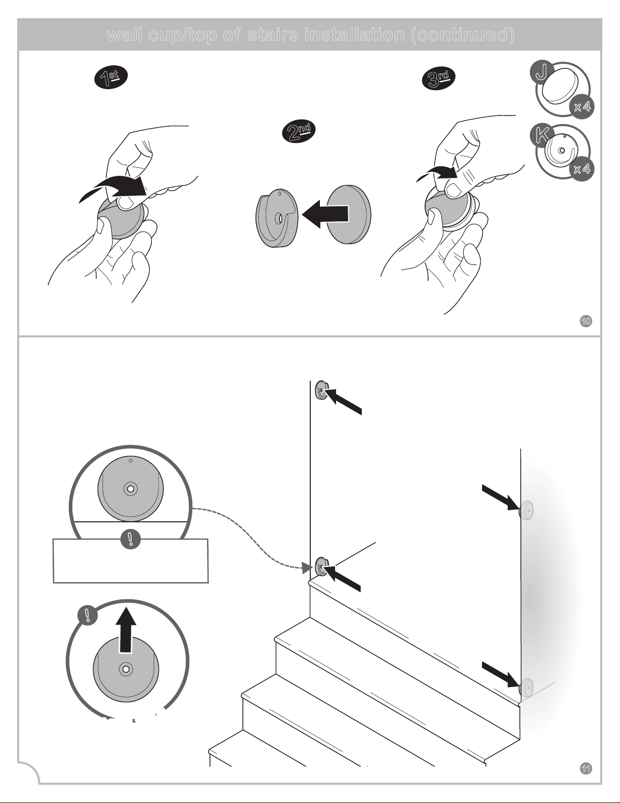
Attach one pad to
the back of each
wall cup.
peel
peel
2
nd
3
rd
Remove backing
from one side of each
adhesive mounting pad.
Remove
backing.
1
st
10
wall cup/top of stairs installation (continued)
press
press
press
press
11
8
x 4
J
x 4
K
Align the wall cups so
the center hole is placed
directly over the wall anchor.
Stick wall cups to the wall.
Make sure
all wall cups
are facing up.
Make sure
all wall cups
are facing up.
!
!
Note: The bottom wall cups
should rest on the floor.
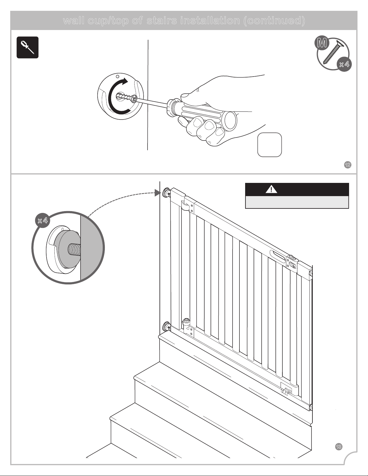
x4
Screw
wall cups
into wall.
x 4
Repeat "installation"
steps on page 5.
The 4 tension bolts
will rest within
each wall cup.
x 4
wall cup/top of stairs installation (continued)
12
13
9
M
NEVER open gate door over stairs.
IMPORTANT
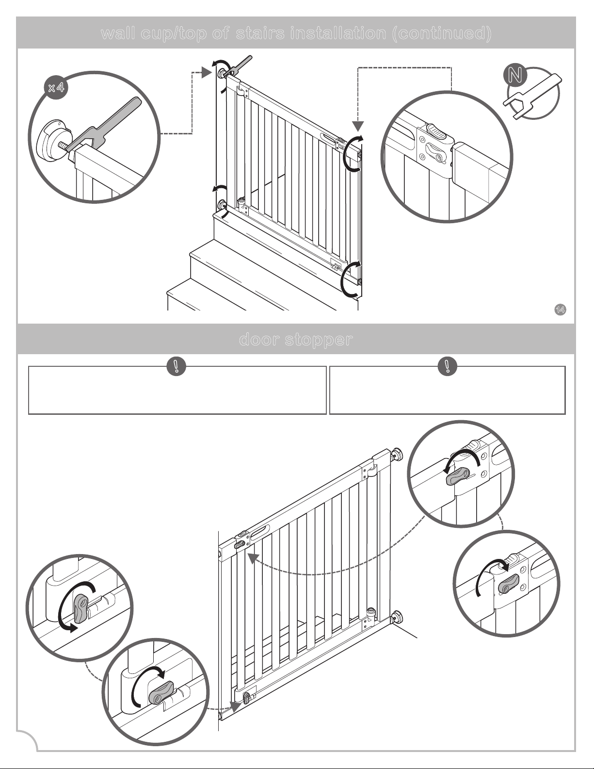
door stopper
N
Tighten all 4
tension nuts
with the provided
wrench.
wall cup/top of stairs installation (continued)
x 4
14
10
Note: This gate includes door stoppers which prevents the
gate from swinging open in one direction when used at the
top of the stairs.
!
Note: Both door stoppers should be turned
on the opposite side of the stairs, when the
gate is installed.
!
When door stopper is not needed, rotate
both door stoppers so they are no longer
overlapping the gate frame.
This will allow the gate to open in either direction.
FINISHED!
When mounting this product at the top of the stairs,
locate the door stoppers on the top and bottom of the gate,
that are on the opposite side of the stairs.
Swing the door stoppers to overlap the gate frame,
so that the door cannot be opened
over the stairs.
Tighten top tension nuts
so the top latch pins
engage the holes in the
door frame.
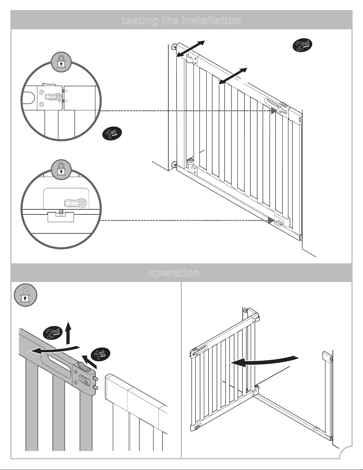
operation
to unlock gate: hold open feature:
To activate,
open gate door
at least 90º in
either direction.
testing the installation
Close the gate.
Make sure the
upper and lower
latches lock
securely.
push!
push!
Push the gate and
extension frames
to check
stability.
1
st
2
nd
11
First, slide locking
tab back to release.
Second, lift gate
door open.
1
st
2
nd
Please retain this information
for future reference.
Colors and styles may vary.
MADE IN CHINA.
12/18
Summer Infant (USA), Inc.
1275 Park East Drive
Woonsocket, RI 02895 USA
401-671-6551
© 2018 Summer Infant (USA), Inc.
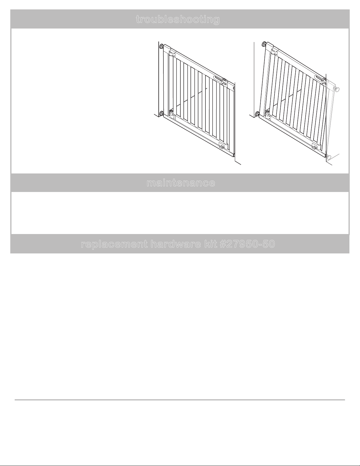
If the gate does not close properly:
1. Gate is not properly aligned in the door
frame.
Solution: To adjust the gate’s alignment,
loosen all four tension bolts and reposition gate
so that it matches the “correct” image.
Re-tighten tension bolts.
2. Pressure of tension bolts needs to be
adjusted.
Solution: Loosen or tighten the upper tension
bolts. Ensure the upper latch engages securely
when the gate swings closed, and that it can be
released properly when the sliding lock tab is
pushed back.
troubleshooting
maintenance
• Regularly check tension bolts to make sure the gate is securely in place.
• Do not use the gate if any components are damaged or missing.
• Surface clean with a damp cloth or sponge using mild detergent and warm water.
correct!
incorrect!
replacement hardware kit #27950-50