
Radar Velometer
User's Manual
V1.0.1

I
Foreword
General
This manual introduces the installation, functions and operations of the Radar Velometer
(hereinafter referred to as "the Device"). Read carefully before using the Device, and keep the manual
safe for future reference.
Safety Instructions
The following signal words might appear in the manual.
Signal Words Meaning
Indicates a high potential hazard which, if not avoided, will result in
death or serious injury.
Indicates a medium or low potential hazard which, if not avoided,
could result in slight or moderate injury.
Indicates a potential risk which, if not avoided, could result in
property damage, data loss, reductions in performance, or
unpredictable results.
Provides methods to help you solve a problem or save time.
Provides additional information as a supplement to the text.
Revision History
Version Revision Content Release Time
V1.0.1 Updated "Important Safeguards and Warnings" and images. August 2022
V1.0.0 First release. March 2022
Privacy Protection Notice
As the Device user or data controller, you might collect the personal data of others such as their face,
fingerprints, and license plate number. You need to be in compliance with your local privacy
protection laws and regulations to protect the legitimate rights and interests of other people by
implementing measures which include but are not limited: Providing clear and visible identification
to inform people of the existence of the surveillance area and provide required contact information.
About the Manual
●
The manual is for reference only. Slight differences might be found between the manual and the
product.
●
We are not liable for losses incurred due to operating the product in ways that are not in
compliance with the manual.
●
The manual will be updated according to the latest laws and regulations of related jurisdictions.
For detailed information, see the paper user’s manual, use our CD-ROM, scan the QR code or visit
our official website. The manual is for reference only. Slight differences might be found between
the electronic version and the paper version.

II
●
All designs and software are subject to change without prior written notice. Product updates
might result in some differences appearing between the actual product and the manual. Please
contact customer service for the latest program and supplementary documentation.
●
There might be errors in the print or deviations in the description of the functions, operations
and technical data. If there is any doubt or dispute, we reserve the right of final explanation.
●
Upgrade the reader software or try other mainstream reader software if the manual (in PDF
format) cannot be opened.
●
All trademarks, registered trademarks and company names in the manual are properties of their
respective owners.
●
Please visit our website, contact the supplier or customer service if any problems occur while
using the Device.
●
If there is any uncertainty or controversy, we reserve the right of final explanation.

III
Important Safeguards and Warnings
This section introduces content covering the proper handling of the Device, hazard prevention, and
prevention of property damage. Read carefully before using the Device, and comply with the
guidelines when using it.
Transportation Requirements
●
Pack the Device with packaging provided by its manufacturer or packaging of the same quality
before transporting it.
●
Transport the Device under allowed humidity and temperature conditions.
Storage Requirements
Store the Device under allowed humidity and temperature conditions.
Installation Requirements
●
To avoid damage to the hard disk, the Device must be carefully installed in a horizontal position.
The device must never be placed in an inclined or vertical position.
●
Do not connect the MCB to the Device while the MCB is powered on.
●
Strictly comply with the local electrical safety code and standards. Make sure the ambient voltage
is stable and meets the power supply requirements of the device.
●
Do not connect the Device to two or more kinds of power supplies, to avoid damage to the
Device.
●
Use the accessories suggested by the manufacturer. Installation and maintenance must be
performed by qualified professionals.
●
When using a laser beam device, avoid exposing the surface of the Device to laser beam
radiation.
●
Personnel working at heights must take all necessary measures to ensure personal safety
including wearing a helmet and safety belts.
●
Do not place the Device in a place exposed to sunlight or near heat sources.
●
Keep the Device away from dampness, dust, and soot.
●
Put the Device in a well-ventilated place, and do not block its ventilation.
●
Use an adapter or cabinet power supply provided by the manufacturer.
●
The power supply must conform to the requirements of ES1 in IEC 62368-1 standard and be no
higher than PS2. Please note that the power supply requirements are subject to the Device label.
●
The device is a class I electrical appliance. Make sure that the power supply of the Device is
connected to a power socket with protective earthing.
●
Operating temperature: –40 °C to +65 °C (–32 °F to +149 °F).
●
The rated current of the Device is 5 A and the rated power is 2000 W.

IV
●
The power and communication port of the Device can sustain a surge of±6 KV in common mode
and±4 KV in differential mode. Extra surge protection is required when the Device is connected
to a circuit with higher surge levels.
●
To ensure heat dissipation, the gap between the Device and the surrounding area should not be
less than 50 mm on the sides and 50 mm on top of the Device.
●
A safety circuit breaker is designed on the connector of the Device to cut the power of the
Device. Make sure the breaker can be easily operated during installation.
●
Only applicable for use in altitudes below 2,000 meters.
Operation Requirements
This is a class A product. In a domestic environment this may cause radio interference in which case
you may be required to take adequate measures.
●
Make sure that the power supply is correct before use.
●
Do not unplug the power cord on the side of the Device while the adapter is powered on.
●
Operate the Device within the rated range of power input and output.
●
Use the Device under allowed humidity and temperature conditions.
●
Do not drop or splash liquid onto the Device, and make sure that there is no object filled with
liquid on the Device to prevent liquid from flowing into it.
●
Do not disassemble the Device.
●
We recommend you use the Device with a lightning protection device for stronger protection
against lightning. For outdoor scenarios, strictly comply with the lightning protection
regulations.
●
Protect the line cord and wires from being walked on or squeezed particularly at plugs, power
sockets, and the point where they exit from the Device.
●
Do not block the ventilation near the Device.
●
Do not vibrate, squeeze or immerse the Device in liquid.
●
Ground the function earthing portion of the Device to improve its reliability. The device is a class I
electrical appliance. Make sure that the power supply of the Device is connected to a power
socket with protective earthing.
●
Prevent water from flowing into the Device during on-site installation to avoid the risk of
damage.
●
Do not place an open flame on the Device, such as a lit candle.
●
The device is applicable for DC power supplies with the negative pole grounded.
●
Replace unwanted batteries with new batteries of the same type and model. To prevent
explosion, replace the battery with the correct model and dispose of the old ones as instructed.
●
Do not expose the battery to extremely hot environments, such as direct sunlight and fire.
Maintenance Requirements
●
Clean the Device with a soft dry cloth or a clean soft cloth dipped in neutral detergent.
●
Use the accessories suggested by the manufacturer. Installation and maintenance must be
performed by qualified professionals.

V
●
Power off the Device before maintenance.
●
Clean the dust off the circuit board, connectors and the cabinet to avoid the device short
circuiting due to dampness.
●
Make sure the Device is properly grounded to avoid being damaged by static electricity or
induced voltage.
●
Do not plug in or unplug RS-232, RS-485 and other ports while the power is on to avoid damage
to the ports.
●
Keep the area around the Device cabinet well-ventilated.
●
Regularly inspect and perform maintenance on the Device.

VI
Table of Contents
Foreword
........................................................................................................................................................................................................I
Important Safeguards and Warnings
............................................................................................................................................ III
1 Product Introduction
.......................................................................................................................................................................... 1
1.1 Overview
........................................................................................................................................................................................ 1
1.2 Functions
....................................................................................................................................................................................... 1
2 Structure
................................................................................................................................................................................................... 2
2.1 Appearance
................................................................................................................................................................................... 2
2.2 Dimensions
................................................................................................................................................................................... 2
3 Quick Configuration
............................................................................................................................................................................ 3
3.1 Initializing the Device
.............................................................................................................................................................. 3
3.2 Changing IP Address
................................................................................................................................................................ 4
3.3 Upgrading the Device
.............................................................................................................................................................. 4
3.4 Logging in to the Webpage
.................................................................................................................................................. 4
4 Webpage Operations
.......................................................................................................................................................................... 5
4.1 Webpage Introduction
............................................................................................................................................................ 5
4.1.1 Recommended System Requirements
................................................................................................................. 5
4.1.2 Login
..................................................................................................................................................................................... 5
4.1.3 Resetting Password
....................................................................................................................................................... 6
4.1.4 Webpage Functions
....................................................................................................................................................... 7
4.2 Live
.................................................................................................................................................................................................... 8
4.2.1 Video and Picture
........................................................................................................................................................... 8
4.2.2 Video
..................................................................................................................................................................................... 9
4.2.3 Picture
................................................................................................................................................................................ 10
4.3 Radar Configuration
............................................................................................................................................................... 11
4.3.1 Configuring the Radar
................................................................................................................................................ 11
4.3.2 Configuring Radar Visualization
........................................................................................................................... 12
4.4 Data Search
................................................................................................................................................................................. 13
4.4.1 Searching for Vehicles
................................................................................................................................................ 13
4.4.2 Searching for Recordings
.......................................................................................................................................... 15
4.5 Setting
........................................................................................................................................................................................... 16
4.5.1 ITC
......................................................................................................................................................................................... 16
4.5.1.1 Configuring ANPR Snapshot
........................................................................................................................ 16
4.5.1.1.1 Configuring Illegal Capture
............................................................................................................... 16
4.5.1.1.2 Configuring Intelligent Analysis
..................................................................................................... 22
4.5.1.1.3 Configuring Camera Attributes
....................................................................................................... 22

VII
4.5.1.1.4 Configuring Cutout
................................................................................................................................ 25
4.5.1.2 Composition & OSD
.......................................................................................................................................... 26
4.5.1.2.1 Normal Combination
............................................................................................................................. 26
4.5.1.2.2 Setting Merge OSD
................................................................................................................................. 27
4.5.1.2.3 Related Composition
............................................................................................................................. 29
4.5.1.2.4 Setting Video OSD
.................................................................................................................................. 33
4.5.1.2.5 Setting Snapshot OSD
.......................................................................................................................... 34
4.5.1.3 Transfer Offline
................................................................................................................................................... 35
4.5.1.4 Allowlist and Blocklist
..................................................................................................................................... 36
4.5.1.4.1 Setting Allowlist
...................................................................................................................................... 36
4.5.1.4.2 Setting Blocklist
....................................................................................................................................... 38
4.5.1.5 Traffic Flow
............................................................................................................................................................ 38
4.5.1.6 Watermark Verification
.................................................................................................................................. 39
4.5.1.6.1 Picture Verification
................................................................................................................................ 39
4.5.1.6.2 Video Verification
................................................................................................................................... 39
4.5.2 Network Settings
.......................................................................................................................................................... 40
4.5.2.1 TCP/IP
....................................................................................................................................................................... 40
4.5.2.2 Port
............................................................................................................................................................................ 41
4.5.2.2.1 Port
................................................................................................................................................................. 41
4.5.2.2.2 ONVIF
............................................................................................................................................................ 41
4.5.2.3 Auto Registration
............................................................................................................................................... 42
4.5.2.4 Flow Statistics
...................................................................................................................................................... 43
4.5.2.5 IEEE802
.................................................................................................................................................................... 43
4.5.2.6 Routing Settings
................................................................................................................................................. 44
4.5.3 Event Management
...................................................................................................................................................... 44
4.5.3.1 Setting Relay Activation
................................................................................................................................. 44
4.5.3.2 Abnormality
.......................................................................................................................................................... 45
4.5.3.3 Testing Alarm I/O Output
............................................................................................................................... 46
4.5.4 Peripheral
......................................................................................................................................................................... 47
4.5.4.1 Extra Device Status
........................................................................................................................................... 47
4.5.4.2 Light Configuration
.......................................................................................................................................... 47
4.5.5 Storage Management
................................................................................................................................................. 48
4.5.5.1 Storage
.................................................................................................................................................................... 48
4.5.5.1.1 Local Storage
............................................................................................................................................. 48
4.5.5.1.2 Smart Info
................................................................................................................................................... 49
4.5.5.2 FTP Storage
........................................................................................................................................................... 49
4.5.5.3 Recording
............................................................................................................................................................... 51
4.5.5.3.1 Record Control
.......................................................................................................................................... 51

VIII
4.5.5.3.2 Record Plan
................................................................................................................................................ 52
4.5.5.3.3 Video
............................................................................................................................................................. 53
4.5.5.4 Snapshot
................................................................................................................................................................ 54
4.5.6 System
................................................................................................................................................................................ 55
4.5.6.1 General
.................................................................................................................................................................... 55
4.5.6.1.1 General Settings
...................................................................................................................................... 55
4.5.6.1.2 Date & Time
................................................................................................................................................ 56
4.5.6.2 Local Setting
......................................................................................................................................................... 57
4.5.6.3 Account Management
..................................................................................................................................... 57
4.5.6.3.1 Managing Users
....................................................................................................................................... 57
4.5.6.3.3 ONVIF User
................................................................................................................................................. 59
4.5.6.4 Safety
....................................................................................................................................................................... 60
4.5.6.4.1 System Service
.......................................................................................................................................... 60
4.5.6.4.2 HTTPS
............................................................................................................................................................ 61
4.5.6.4.3 Firewall
......................................................................................................................................................... 65
4.5.6.5 Default
..................................................................................................................................................................... 65
4.5.6.6 Import/Export
...................................................................................................................................................... 65
4.5.6.7 Auto Maintain
...................................................................................................................................................... 66
4.5.6.8 System Upgrade
................................................................................................................................................. 66
4.5.7 System Information
..................................................................................................................................................... 67
4.5.7.1 Version Information
......................................................................................................................................... 67
4.5.7.2 Log
............................................................................................................................................................................. 67
4.5.7.2.1 System Log
................................................................................................................................................. 67
4.5.7.2.2 Remote Log
................................................................................................................................................ 68
4.5.7.3 Viewing Online User
......................................................................................................................................... 68
4.5.7.4 Legal Information
.............................................................................................................................................. 68
4.6 Alarm
.............................................................................................................................................................................................. 69
4.7 Logout
........................................................................................................................................................................................... 69
Appendix 1 Reference for Filling in Allowlist and Blocklist Template
......................................................................... 70
Appendix 2 Cybersecurity Recommendations
........................................................................................................................ 73

1
1 Product Introduction
1.1 Overview
The Device measures the real-time speed of vehicles with high precision and accuracy. It integrates a
24 GHz radar, 2 cameras and a deep learning edge storage terminal in respect of structure, achieving
multi-dimensional traffic information collection and violation capture.
The Device is ideal for use in scenarios that require vehicle related event detection and traffic data
collection. Use it on highways, urban expressways, urban roads, intersections and other similar
locations.
1.2 Functions
Multiple Lanes Detection
Event detection for up to 6 lanes.
Automatic Calibration
Flexible parameter configuration, and automatic calibration of radar and video targets.
Multi-dimensional Traffic
The Device integrates functions of 24 GHz radar and deep-learning camera in respect of structure,
scenario application, and traffic information collection to deliver high-precision data.
Data Search
Offers live view and history data search for videos and images, and custom filter search for events
and license plates.
Wide Range Detection
Monitors 4 dual-way lanes and tracks 128 targets. The motor vehicle detection distance is up to 250
m.
Intelligent Recognition
●
Built-in advanced AI algorithm that realizes the intelligent recognition of multiple vehicle
features.
●
Detects a variety of activities such as speeding and driving slow.

2
2 Structure
2.1 Appearance
Figure 2-1 Device appearance
2.2 Dimensions
Figure 2-2 Dimensions (mm [inch])

3
3 Quick Configuration
You can use the ConfigTool to quickly configure the Device, including initialization, system update
and webpage login.
●
The operation pages vary depending on different versions.
●
Get the ConfigTool installation package from technical support and install it on your local
computer.
3.1 Initializing the Device
You can initialize the Device, and cameras connected to the Device in batches through the
ConfigTool.
Uninitialized devices are not available for any operations and are displayed in gray on the Device list.
Step 1 Start the ConfigTool, and then click
Modify IP
.
The ConfigTool automatically searches for devices on the same network segment with the
computer.
Step 2 Select a device to be initialized, and then click
Initialize
.
Figure 3-1 Device initialization
Step 3 Set and confirm the password, and enter an email for future password reset.
The pages are for reference only, and might differ from the actual page.
Step 4 Click
Initialize
, and the system starts initializing the Device.
is displayed for successful initialization, and is displayed for initialization failure.
Click the icon to view details.
Step 5 Click
Finish
.

4
3.2 Changing IP Address
You can acquire and change the IP address of devices accessed through wired network. This section
uses changing IP address with the ConfigTool as the example.
Step 1 Start the ConfigTool.
Step 2 Click
Modify IP
.
Step 3 Select the device(s) whose IP need(s) to be changed.
●
Change one IP address: Click
Edit
corresponding to the device.
●
Change IP addresses in batches: Select the devices, and then click
Batch Modify IP
.
Step 4 Set mode, IP, subnet mask and gateway.
Step 5 Click
OK
.
Figure 3-2 Change IP addresses in batches
3.3 Upgrading the Device
Single upgrade and batch upgrade are supported.
Step 1 Start the ConfigTool.
Step 2 Click
Device Upgrade
.
Step 3 Select the Device to be updated.
●
Update one by one: Click corresponding to the Device.
●
Update in batches: Select multiple devices, and then click
Batch Upgrade
.
Step 4 Select the update file.
Step 5 Update the Device.
●
Update one by one: Click to start updating.
●
Update in batches: Click
OK
to start updating.
During update, if the Device is disconnected, as long as the ConfigTool stays on the update
page, the upgrade will continue when the Device is reconnected.
3.4 Logging in to the Webpage
On the
Modify IP
page, click
Web
corresponding to the Device, and then you are directed to the
login page of the webpage. Enter the login username and password to log in.

5
4 Webpage Operations
You can access and manage connected devices, such as cameras and radars through the webpage of
the Device.
The web pages displayed in this section are for reference only, and might differ from the actual
model.
4.1 Webpage Introduction
Log in to the webpage of the Device through a browser, on which you can operate, configure and
maintain the Device.
4.1.1 Recommended System Requirements
Table 4-1 Recommended system requirements
Component Recommended System Requirements
Operating system Windows 7 and later.
CPU Intel core i3 and later.
Graphics card Intel HD Graphics and later.
Memory 2 GB and bigger.
Monitor resolution 1024 × 768 and higher.
Browser Internet Explorer 11, Chrome 41/33, and Firefox 49.
4.1.2 Login
●
For first-time login or login after the Device is restored to factory defaults, initialization is
required.
●
Make sure that the IP address of the computer and that of the Device are on the same network
segment. Otherwise, the initialization might fail.
Step 1 Open the browser and enter the IP address of the Device, and then press the Enter key.
Step 2 Enter and confirm the password.
Change the password from
Setting
>
System
>
Account
>
Account
>
Username
. For
details, see "4.5.6.3.1 Managing Users".

6
Figure 4-1 Device initialization
Step 3 Select
Email Address
, and then enter an email address.
The email address is used for resetting password.
Step 4 Click
Confirm
.
Step 5 Enter
Username
and
Password
on the login window, and then click
Login
.
The account will be locked for five minutes after five failed username or password
attempts.
Step 6 On the
Live
page, click
Please click here to download and install the plug-in
to
download and install the plug-in.
The
Live
page is normally displayed.
4.1.3 Resetting Password
When you forget the password, you can set a new password.
●
You need to enter an email address during device initialization to receive the security code.
Otherwise, password reset is not available. You can also change the email address from
Setting
>
System
>
Account
>
Account
>
Username
. For details, see "
4.5.6.3.1 Managing Users".
●
The password of a device can only be reset up to 10 times a day.
●
You can only get two security codes for each QR code.
●
Use the security code to reset the password within 24 hours after you receive it. Otherwise the
security code will become invalid.
Step 1 Open the browser and enter the IP address of the Device, and then press Enter.
Step 2 Click
Forgot password?
on the login page, and then click
OK
in the pop-up window.
If Internet Explorer is used,
Stop running this script
is displayed. In this case, click
No
to
continue to run the script.
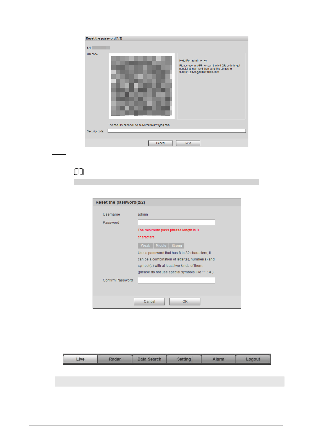
Step 3 Scan the QR code, and the scan result will be sent to the reserved email.
Step 4 Send the received scan result to support_gpwd@htmicrochip.com through the reserved
email address to get the security code.
7
Figure 4-2 Reset password (1)
Step 5 Enter the security code, and then click
Next
.
Step 6 Enter and confirm the new password.
Follow the password security prompt to set a password with a high security level.
Figure 4-3 Reset password (2)
Step 7 Click
OK
.
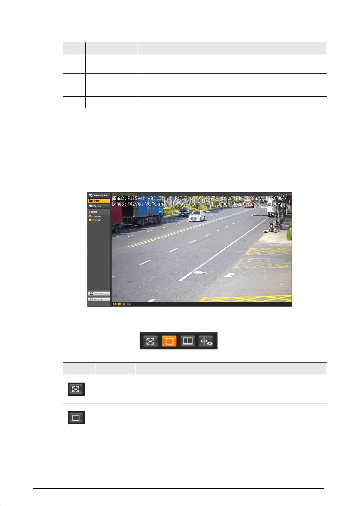
4.1.4 Webpage Functions
Figure 4-4 Tabs
Table 4-2 Tab functions
Function Content
Live View the real-time videos and captures of the camera.
Radar Configure the radar and debug the detection result.

8
Function Content
Data Search Search for vehicles and recordings.
Setting
Configure intelligent traffic rules, the basic attributes of the Device, network
settings, event management, storage management, system management, and
view system information.
Alarm Set alarm prompts.
Logout Log out of the webpage.
The common buttons on the webpage are as follows.
Table 4-3 Common buttons
Button Description
Restores the parameter to the default value.
Restores the parameter to the value saved last time.
Saves current configurations.
4.2 Live
The
Live
page displays real-time videos of the connected cameras, real-time snapshots, and
recognized plates.
4.2.1 Video and Picture
You can view the videos and snapshots of a channel and the details of captured vehicles.
Log in to the webpage, select
Live
>
Video && Pic
, and then click a channel.
Figure 4-5 Video and picture
9
Table 4-4 Video/picture live view page description
No. Module Name Description
1 Channel
Select a channel for live view, and you can select to view live videos,
pictures or both on the same page.
2 Live view The real-time video of the selected channel.
3 Picture window Displays the snapshot of the recognized vehicle.
4 Event details Displays the details of recognized violations.
4.2.2 Video
You can view the live video of multiple channels at the same time. Log in to the webpage, select
Live > Video
, and then click a channel, and the
Live
page of this channel is displayed. See Figure 4-6.
The pane selected area on the page is the video window setting bar. See Figure 4-7. For icon
description, see Table 4-5.
Figure 4-6 Live view
Figure 4-7 Video window setting bar
Table 4-5 Video window setting description
Icon Name Description
Full screen
●
Click the icon to switch to the full screen mode.
●
Double-click anywhere on the screen or press Esc to exit the full
screen.
1 window
Default image display mode.
Select any video channel in the list on the left side for live view
directly in a single window.

10
Icon Name Description
2 windows
Equally divide the live view window into 2 windows. Live view
channels and display positions can be customized.
1. Click a window to be set, and the border of this window turns
green.
2. Select the channel number for live view in this window in the list
on the left side.
3. Repeat the earlier steps for other windows until every window
displays the required channel images.
Click
Open All
or
Close All
below the channel list to quickly open or
close all channels, and the opened channels will be displayed in the
order of channel numbers from left to right and top to bottom in the
live view windows.
Bounding
box
Click the icon to display the smart tracks uploaded by the camera.
Smart tracks such as non-motor vehicle and motor vehicle detection
boxes are displayed on the video.
In
Setting
>
Remote Device
>
Remote Device
, set
RTSP Steaming
Media
as the protocol type of main stream/sub stream of camera.
The Device will not display bounding boxes unless the address
contains proto=Private3.
4.2.3 Picture
The live view of pictures of multiple channels at the same time is available. You can view details of
captured vehicles.
Log in to the webpage, select
Live
>
Picture
, and then click a channel, and the
Picture
page of this
channel is displayed.
For details, see "4.2.1 Video and Picture" and "4.2.2 Video" for operations on this page.
Figure 4-8 Live view of picture

11
4.3 Radar Configuration
Configure the radar to accurately capture events during bad weathers and poor light conditions.
4.3.1 Configuring the Radar
Set the parameters of the radar and lanes, and calibrate the radar. Make sure that when the radar
sends signals to the camera, the camera can capture the right target.
Step 1 Select
Radar
>
Radar Settings
.
The information of the connected radar is displayed on the top of the page, and you can
adjust the sensitivity.
Under general situations, we recommend you leave the sensitivity as default to avoid false
detections.
Step 2 Set the lane width and direction based on the actual site.
Figure 4-9 Lane information
Step 3 Click
Calibrate by Radar & Video
.
Step 4 Select a channel on the prompted page, and then select the
Splicing Calibration
checkbox.
You can also calibrate the radar manually without enabling splicing calibration. In this case,
you need to manually measure the distance between the drawn calibration area and the
Device.

12
Figure 4-10 Radar calibration
Step 5 Calibrate the radar.
●
Manual calibration
Set the coordinates of the calibration area and the trigger distance manually.
In situations where manual measurement is accurate, the precision of manual
calibration is higher than automatic calibration.
1) Select
Manual
next to
Calibration Mode
, and then adjust the calibration frame on the
image based on the on-site measurement.
You can also click , and then click
Calibration Area
to draw an area on the image.
2) Set the coordinates of the calibration area.
3) In the
Snapshot Setting
section, click
Snapshot Triggering Line
, and then draw the
lines on each lane.
The distance between the triggering line and the Device is displayed on the bottom.
4) Adjust the triggering distance as needed, and then click
Confirm
.
5) Click
Calibrate
, and then click
Confirm
.
●
Automatic calibration
Set the width of the calibration area to be the same as that of the actual road, and then
the algorithm will automatically calibrate the radar.
1) Select
Auto
next to
Calibration Mode
.
2) Set the
Area Width
according to the actual width of the road.
3) Click
Calibrate
, and then click
Confirm
.
Step 6 Click
Back
, and then in the
Installation Settings
section, set the installation height of the
Device and the angle correction and horizontal offset of the radar inside the Device.
Step 7 Click
Confirm
.
Click the
Radar Visualization
tab to view the effect of radar detection.
4.3.2 Configuring Radar Visualization
See the effect of your configurations on radar detection in real time. You can also adjust some of the
radar parameters and view the changes.
Step 1 Select
Radar
>
Radar Visualization
.
Step 2 Adjust the value of angle correction and horizontal offset.
Click the image at the lower-right corner to see the correction standards.

13
Step 3 Click to turn on
Target Trajectory
.
You can see the trajectory of targets the radar detects.
Figure 4-11 Radar visualization
Step 4 Click , you can see the detection points of the radar on targets.
When the target is large and the detection sensitivity is set high, the radar might recognize
it as two targets.
4.4 Data Search
You can set search conditions to search for vehicles or recordings, and set file or time as download
type to download related data.
4.4.1 Searching for Vehicles
Step 1 Click
Data Search
, and then select
Vehicle
.
Step 2 Set vehicle search conditions.
1) Set basic parameters such as the period, channel and picture type.
2) Click
Advanced Options
, and then select detailed options as needed.
●
When searching for records through plate numbers, fuzzy match is available.
●
Multiple selections are available.
3) Select whether to only search for composed pictures and vehicles on the blocklist.
Step 3 Click
Query
.
Click a record on the list to view the picture on top.

14
Figure 4-12 Search for vehicles
Step 4 Select the download type, and then click
Download
.
●
File
: Select one or more pictures to download from the search results.
●
Time
: Download all pictures taken during the set period.
●
Cutout Type
: Select the cutout type of pictures to be downloaded. When downloading
pictures, the related cutout image will be separated and downloaded together.
Step 5 Click
Pic Rename
, click
Help
next to the corresponding picture type, and then customize
the picture naming format in the pop-up window.
Figure 4-13 Picture naming format
You can add up to 76 items when setting the naming format.
Step 6 Click
Confirm
.
Step 7 Set the duration of
Related Record
, and then download related records as needed.
Related records cannot be displayed until the camera and the Device are synchronized in
time.
15
●
Click
Related Video
to view the video. During playback, you can use the buttons on
the progress bar to play, pause, stop, and quick play the video. During playback, the
channel name, time, and other information of the recordings are displayed on the
video image.
●
To download related records only, directly select from the search results, and then click
Download Related
.
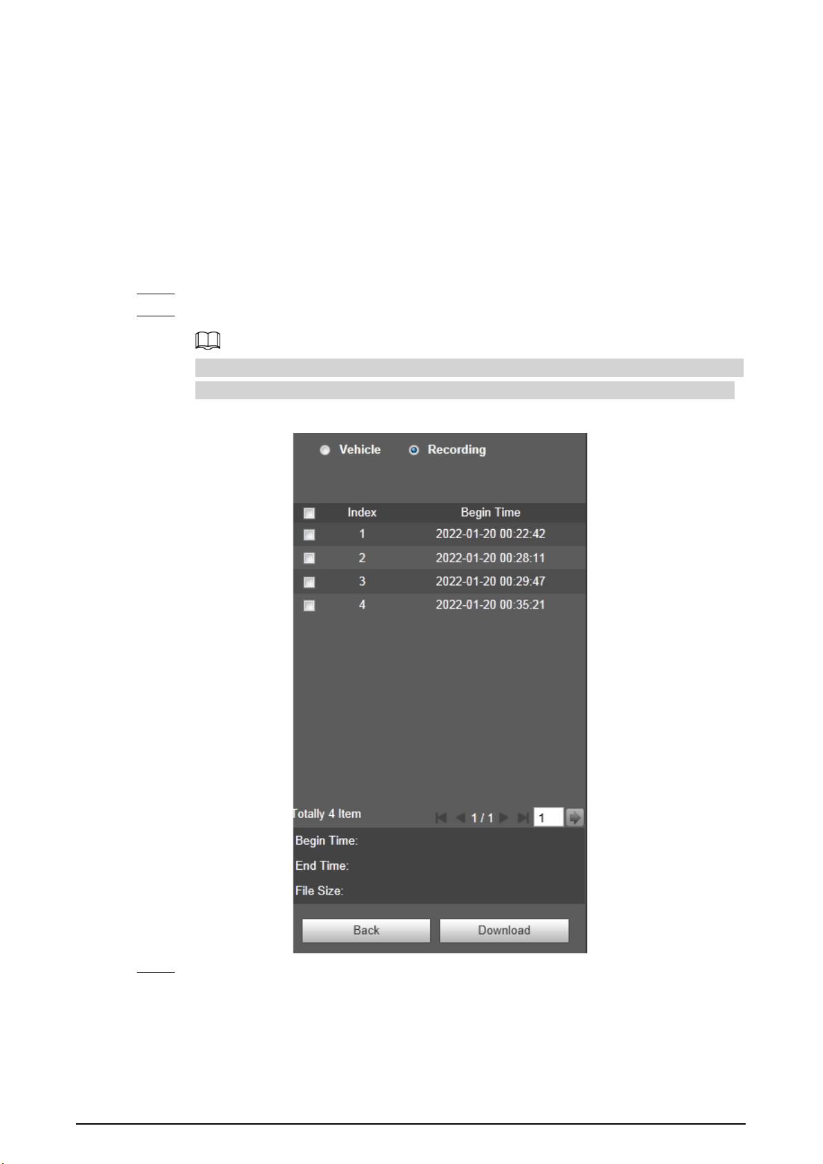
4.4.2 Searching for Recordings
Step 1 Click
Data Search
, and then select
Recording
.
Step 2 Set the query time and channel, and then click
Query
.
After the query time and channel are set, select
Time
from
Download Type
, and then click
Download
to directly download all recordings of the specified channel within this period.
Figure 4-14 Query results
Step 3 Double-click a query result to view the recording. Click the buttons on the play bar to
control the playback.

16
Table 4-6 Description of playback buttons
Icon Name
Play/Pause
Stop
Slow down
Speed up
Play speed
Step 4 Select a recording, and then click
Download
to download the selected recording to local
computer.
4.5 Setting
Set parameters of the Device, including intelligent traffic rules, network settings, remote devices,
event management, storage management, system management, and system information, to realize
functions such as image composition, speed measuring, network connection, data storage and
alarm.
4.5.1 ITC
You can configure intelligent traffic parameters to provide functions such as image mosaic and OSD
configuration.
4.5.1.1 Configuring ANPR Snapshot
4.5.1.1.1 Configuring Illegal Capture
Configure the video detection parameters for detecting traffic violations.
Click to select a lane on the list in the
Lane Config
section, and then all configurations on the
Illegal
Capture
page are for this lane.
Lane Parameters
Configure the information of the lanes the Device is monitoring, such as drawing the lane lines on
the image, select the lane direction and set the lane line type according to the actual situation.
Step 1 Select
Setting
>
Event
>
ANPR Snap
>
Illegal Capture
Step 2 In the
Lane Config
section, configure the lane lines.
●
If the default lane lines on the image do not meet the actual detection requirements,
you can draw new lane lines.
1. Select a lane from the list, and then delete the lines by clicking .

17
You can also click next to
LaneLine
or
Detect Line
to delete the corresponding
lines on the image.
2. Click
LaneLine
or
Detect Line
, and then draw lines on the image.
When a vehicle reaches the detection line, a snapshot is triggered.
●
If the default lane lines can be adjusted to match the actual lane lines, you can adjust
them.
1. Select
Graphic Adjustment
to enable lane line adjustment, and then select a lane
from the list.
2. Drag to adjust the lane lines and detection lines according to the actual situation.
Figure 4-15 Lane configuration
Step 3 For the selected lane, select
Lane Direction
and
Flow
.
●
Lane Direction
: The direction of the lane line on the image needs to be the same as
that of the travelling vehicle.
●
Flow
: Select the capturing part of the vehicle and its traveling direction. This is normally
used for traffic flow analysis.
Step 4 Double-click the selected lane on the list under
Left Lane Line Type
,
Right Lane Line
Type
and
CarWay Type
to change the lane lines and lane type as needed.
●
Click to display or hide the corresponding lanes on the image.
●
Click to select a lane for the Device to monitor and detect events on.
●
Click to delete the corresponding lane lines on the image.
Step 5 Click
Confirm
.
Lane Property
For the selected lane in the
Lane Config
section, you can set its road direction and code.
Step 1 Select
Setting
>
Event
>
ANPR Snap
>
Illegal Capture
.
Step 2 Select a lane from the list under
Lane Config
.
Step 3 In the
Lane Property
section, configure lane properties.

18
Figure 4-16 Lane property
Table 4-7 Lane property description
Parameter Description
Road Direction The direction of the lane.
RoadDirection The geographical direction of the lane.
Roadway Code
The code of the roadway and route.
Route Code
Step 4 Click
Confirm
.
Car Detect
Draw the regions for vehicle detection on the image.
Step 1 Select
Setting
>
Event
>
ANPR Snap
>
Illegal Capture
.
Step 2 In the
Car Detect
section, click a line or region type, and then draw on the video image.
●
To draw a line, click the line type, and then draw on the image.
●
To draw a region, click the region type, and then click on the image to set the four
points of the region.
To clear the lines that you have drawn, click .
Figure 4-17 Line or region types
Table 4-8 Car detect description
Parameter Description
Region The region of detection.
Car Region The region for detecting vehicle volume.
Match Line
When the radar inside the Device detects an event around the match
line, it sends a signal to the Device to take a snapshot.
Step 3 Click
Confirm
.
Rule Configuration
For the selected lane in the
Lane Config
section, you can select the traffic violation types and
configure the corresponding parameters of the snapshot, trigger source and flashing light.
Step 1 Select
Setting
>
ITC
>
ANPR Snap
>
Illegal Capture
.
Step 2 Select a lane from the list under
Lane Config
.
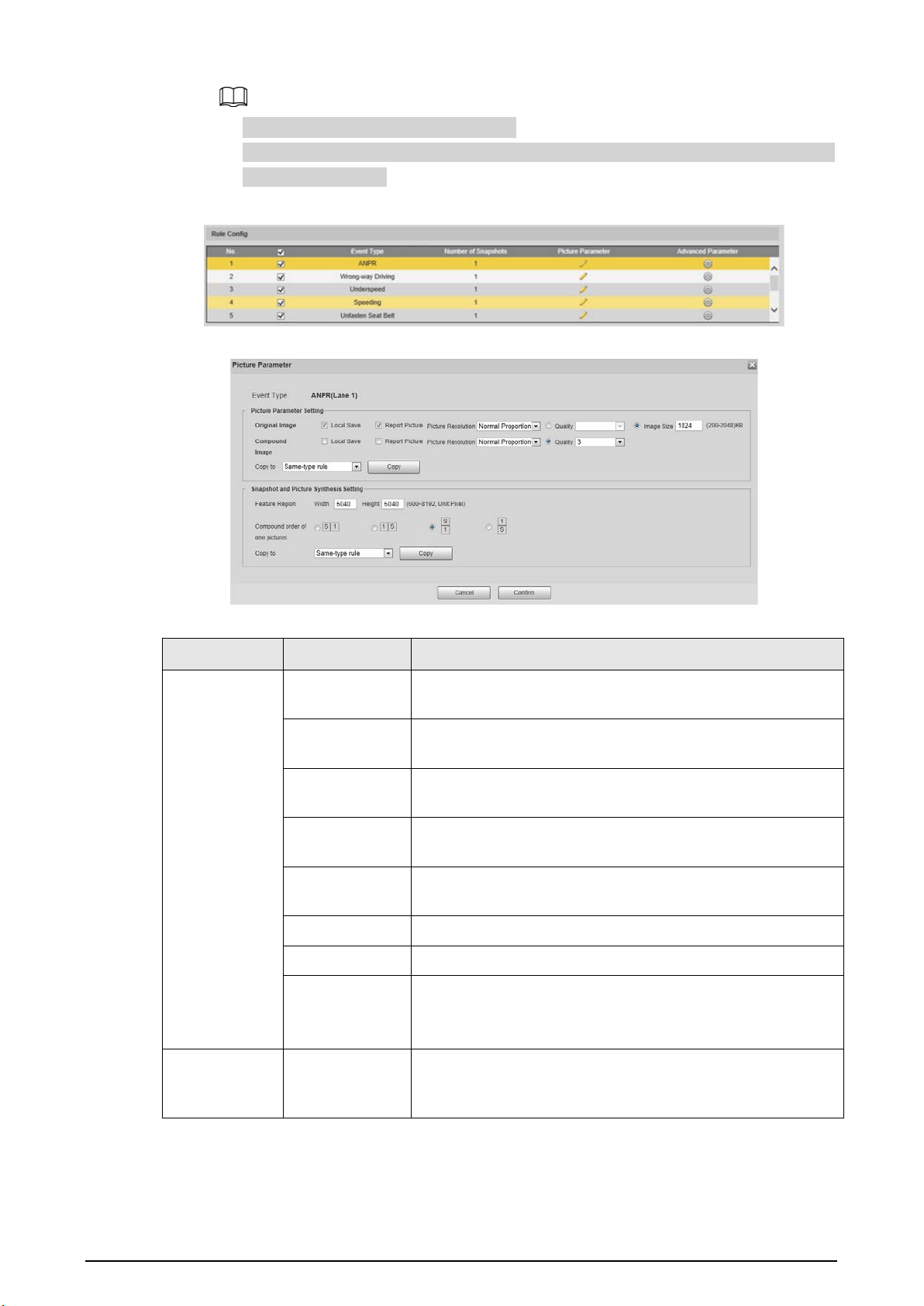
Step 3 In the
Rule Config
section, select of an event, and the click the corresponding to
configure the snapshot parameters.
19
●
In this part,
ANPR
is used as an example.
●
The parameters displayed in the following page are for reference only, and might differ
from the actual page.
Figure 4-18 Rule configuration
Figure 4-19 Configure picture parameter
Table 4-9 Picture parameter
Category Name Description
Picture
Parameter
Setting
Original Image
The original picture of the vehicle that is violating traffic
rules.
Compound
Image
The composite picture of several sequential images of the
vehicle violating the traffic rules.
Local Save
Save the vehicle picture to your computer when a vehicle is
captured.
Report Picture
Upload the picture to the upper-level device or platform
when a vehicle is captured.
Picture
Resolution
Select the resolution of the picture.
Quality Select the quality level of the picture.
Image Size Set the limit of the picture size.
Copy to
Copy the current picture configurations to the same-type
rule or all the rules of another lane.
After selecting an option from
Copy to
, click
Copy
.
Snapshot and
Picture
Synthesis
Feature Region
Set the width and height of the feature region on a vehicle
snapshot, which will be used as the close-up image to
combine with other snapshots.

20
Category Name Description
Setting
Compound
order of one
pictures
Select the layout of the composite picture. It consists of N
original snapshots and one close-up of the vehicle.
●
S
: Close-up
●
1
: Original snapshot
Step 4 Click
Confirm
.
Step 5 Click , and then configure advanced parameters of the rule.
Figure 4-20 Advanced parameters
Table 4-10 Advanced parameter description
Parameter Description
Trigger Source
●
Loop
: Unavailable.
●
Radar
: The Device captures vehicles upon the radar detecting a
violation.
●
Video Analyse
: The Device analyzes the real-time video to detect
traffic violations. Once a violation is detected, the Device
automatically captures images of the vehicle.

21
Parameter Description
Rule Parameter
●
Vehicle Optimization
: When the vehicle plate to be captured is
blocked, the Device will wait till it is recognizable before taking a
snapshot.
●
Capture Direction
: Travelling direction of vehicles to the Device.
●
Snap Car
: Select the types of vehicles to be captured.
●
Period
: The period during which the alarm is valid.
Click
Setting
, drag on the time table or select days, and then enter
hours on the entry fields.
Flashing Light
Select which flashing light flashes when snapshots are taken during
daytime or night.
●
A snapshot can be associated with up to five flashing lights.
●
Select
F1
in the
1/4Times
section, meaning flashing light F1 flashes
when taking the 1st and 4th snapshots.
Step 6 Click
Confirm
.
Other Settings
Step 1 Select
Setting
>
Event
>
ANPR Snap
>
Illegal Capture
.
Step 2 In the
Other Settings
section, configure parameters.
Figure 4-21 Other settings
Table 4-11 Other settings description
Parameter Description
Radar Calc Speed Uses radar to measure vehicle speed.
Snap Match Mode
●
Common Mode
: Recommended for the ANPR snap mode.
●
Priority Mode
: Recommended for the e-police mode.
Max Speed
When the vehicle speed exceeds this value, the Device
automatically changes the vehicle speed to a random value within
the normal range to filter false alarms.
Pixel Counter
Click
Draw Target
, and then draw a rectangular area on the image
to show the pixel size of that area.
Right-click the area to cancel the pixel counter.

22
Step 3 Click
Confirm
.
4.5.1.1.2 Configuring Intelligent Analysis
Set the recognition objects and algorithm of the intelligent analysis.
Recognition
Select the recognition objects of motor vehicles for each channel.
Step 1 Select
Setting
>
Event
>
ANPR Snap
>
Intelligent Analysis
>
Recognition
.
Step 2 Select a channel, and then select features and actions you want the Device to recognize.
Figure 4-22 Recognition
Step 3 Click
Confirm
.
Advanced
You can make a custom algorithm for recognition.
Step 1 Select
Setting
>
Event
>
ANPR Snap
>
Intelligent Analysis
>
Advanced
.
Step 2 Select a channel, and then configure a custom algorithm.
Step 3 Click
Confirm
.
Intelligence Default
Step 1 Select
Setting
>
Event
>
ANPR Snap
>
Intelligent Analysis
>
Intelligence Default
.
Step 2 Click
Default
to restore settings including lane property, violation capture and intelligent
business to default.
4.5.1.1.3 Configuring Camera Attributes
After connecting the Device to the network and viewing the live video on its webpage, you can
adjust the image parameters of the Device to get clear images.
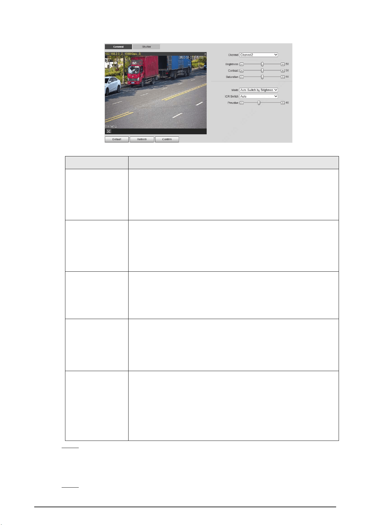
Configuring General Parameters
You can configure the brightness, contrast, saturation, mode, and other properties of the camera
channels.
Step 1 Select
Setting
>
ITC
>
ANPR Snap
>
Camera Attribute
>
General
.
Step 2 Select a channel, and then configure the corresponding parameters.
23
Figure 4-23 General
Table 4-12 General parameters
Parameter Description
Brightness
●
Both the darker areas and the brighter areas will be changed together
when adjusting the brightness. The image might become blurry when
the value gets bigger. The recommended range is 40–60, and the
available range is 0–100.
●
It is 50 by default. The larger the value, the brighter the image.
Contrast
●
The larger the value, the darker the dark area, and the more exposed
the bright area.
●
The image might become blurry when the value gets smaller. The
recommended range is 40–60, and the available range is 0–100.
●
It is 50 by default. The larger the value, the stronger the contrast.
Saturation
●
Saturation value does not change the overall image brightness.
●
The larger the value, the more saturated the image.
●
It is 50 by default. The smaller the value, the more unsaturated the
image. The recommended range is 40–60, and the available range is
0–100.
Mode
●
Colorful
: The image is always colored.
●
Auto Switch by Brightness
: When the brightness is higher than the
threshold, the image automatically changes to color; when it is below
the threshold, the image changes to black and white.
●
B/W
: The image is always black and white.
ICR Switch
●
Auto
: You need to pre-set the brightness in this mode. When the
ambient brightness is higher than the pre-set value, the CPL will start
to work.
●
CPL
: The CPL is always running. Applicable to scenarios with high
brightness.
●
IR
(for IR models) or
Normal
(for white light models): Applicable to
scenarios with low brightness.
Step 3 Click
Confirm
.
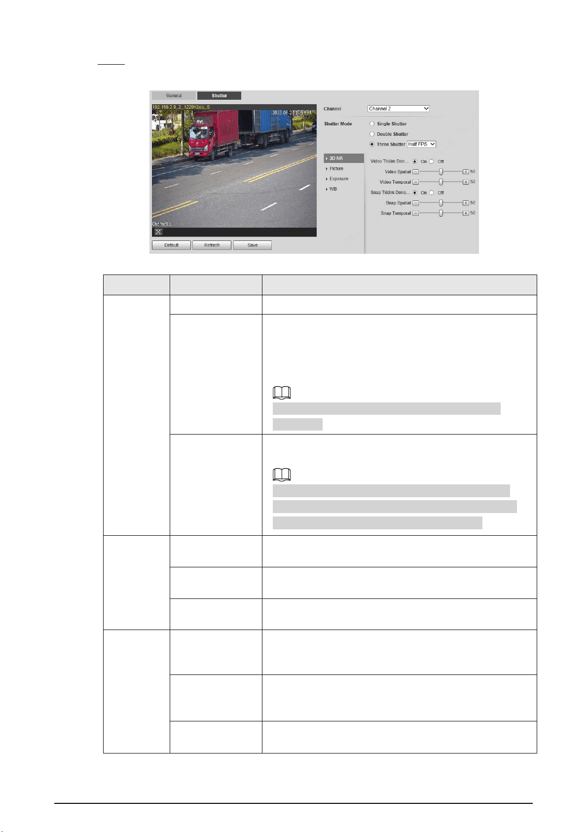
Configuring Shutter
You can configure shutter mode, exposure mode, and gain mode.
Step 1 Select
Setting
>
ITC
>
ANPR Snap
>
Camera Attribute
>
Shutter
.
24
Step 2 Select a channel, and then configure the corresponding parameters.
Figure 4-24 Shutter
Table 4-13 Shutter parameters
Module Parameter Description
Shutter
Mode
Single Shutter Video and snapshot share the same exposure mode.
Double Shutter
●
Half FPS
: Video and snapshot take half of the frame
respectively.
●
Full FPS
: Snapshot takes 1frame, and video takes the
rest of the frames.
Video Shutter
and
Snap Shutter
can be separately
configured.
Three Shutter
Video Shutter
,
Snap Shutter
and
Recognition Shutter
can
be separately configured.
Three Shutter
mode is available only when
Common
Mode
is set to
Snap Match Mode
from
Setting
>
ITC
>
ANPR Snap
>
Illegal Capture
>
Other Settings
.
3D NR
Video/Snap
Tridim Denoise
When it is
On
, 3D NR is enabled to reduce noise of
video/snapshot.
Video/Snap
Spatial
Spatial video/snapshot denoising. The higher the value, the
less noise there is.
Video/Snap
Temporal
Temporal video/snapshot denoising. The higher the value,
the fewer the flicker noise.
Picture
Scene
You can change the scene and adjust the sharpness of the
corresponding scene. Scenes available:
Dawn/Dusk
,
Daytime
, and
Night
.
Sharpness
You can set the sharpness of the corresponding scene.
The higher the value, the clearer the image. But there will be
noise if the sharpness is too high.
WDR
Select
On
to enable WDR (wide dynamic range), which helps
provide clear video images in bright and dark light.

25
Module Parameter Description
Exposure
Mode
●
In
Auto
mode, only
Manual
iris type is available.
●
In
Force
mode, several iris types are available, and you
also need to configure the
Iris Adjust Mode
. If
Manual
is selected, you can manually drag the slider to adjust
the value.
Iris Type Displays the detected iris type.
Mode
Select the way of adjusting exposure mode. You can select
from
Manual
and
Auto
.
Shutter
You can select the shutter value, or select
Customized
Range
, and then set the shutter range.
Only available when
Mode
is set to
Manual
.
Shutter Scope
Set the time range of shutter.
Only available when
Shutter
is set to
Customized Range
.
Gain Scope
Set the value range of gain.
Only available when
Mode
is set to
Manual
.
WB Mode Set scene mode to adjust the image to its best status.
Step 3 Click
Save
.
4.5.1.1.4 Configuring Cutout
The Device supports cropping snapshots and saving the cutouts. In addition, you can overlay the
face cutouts of drivers and front-seat passengers on the snapshots. Enabling bounding box of
vehicles is also available.
Step 1 Select
Setting
>
ITC
>
ANPR Snap
>
Cutout
.
Step 2 Select a channel.
Step 3 In the
Cutout
section, select the
Cutout Type
.
Figure 4-25 Cutout type
Step 4 In the
Track Box
section, select
On
to enable bounding box of vehicles.
Step 5 Select the bounding box type.
You can select whether to overlay speed of the vehicle on the bounding box.
Figure 4-26 Track box
Step 6 In the
Face Overlay
section, select whether to enable face overlay, and then select the
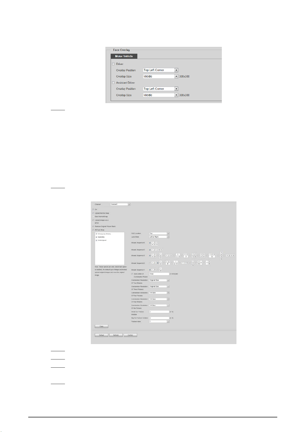
26
overlay position and size of driver and assistant driver faces.
Figure 4-27 Face overlay
Step 7 Click
Confirm
.
4.5.1.2 Composition & OSD
Set the image composition rules and OSD contents.
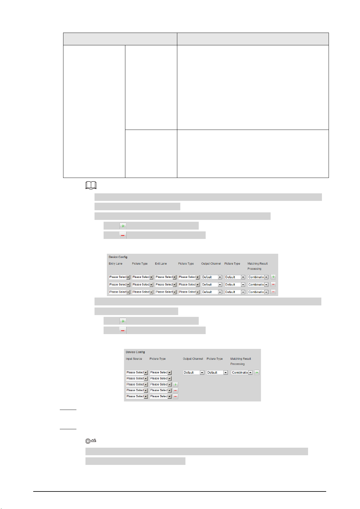
4.5.1.2.1 Normal Combination
Select violation types, set the combination sequence, picture size, and other parameters to form a
picture combined with the information you set.
Step 1 Select
Setting
>
ITC
>
Composition & OSD
>
Normal Combination
.
Figure 4-28 Normal combination
Step 2 Select a channel.
Step 3 Select
On
to enable image mosaic.
Step 4 Select
Upload Normal Snap
as required. If it is not selected, no original picture is
uploaded in the corresponding channel on the live view page.
Step 5 Select
Upload images as a group
, original images will be temporarily saved and uploaded
together with combined images. There is no time difference between the original image
and combined image.

27
Step 6 Select
Remove Original Picture Black
as required.
Step 7 Under
All Type Snap
, select the violation type to enable the combination.
Step 8 Set other parameters.
Table 4-14 Snapshot combination parameters
Parameter Description
OSD Location
Select the location where OSD information is overlaid on the composite
picture. Select
Above
or
Below
, or select
None
without OSD information
overlay.
Mosaic Sequence
Select the correspondence between sequence and location according to
the picture sequence of 1
→
2.
means that the composite pictures are arranged from left to right
and top to bottom.
S means that there is a feature in the composite pictures, and it is the
enlarged feature of a snapshot.
The sequence can be switched at will. Use horizontal 12 as an example,
you can delete the numbers and enter 21.
Size Limit Of
Combination Picture
Select it to enable picture size limit, and set the maximum number of KBs
of composite pictures. It is selected by default.
When this function is enabled, the picture compression ratio setting is
invalid.
●
If it is selected, when the composite picture is larger than 6,144 KB, it
will be automatically compressed to nearly 6,144 KB and displayed
on the webpage.
●
If it is not selected, when the composite picture is larger than 8,192
KB, it will be automatically saved to the HDD and will not be
displayed on the webpage.
Combination
Resolution of X
Pictures
Set the resolution of the composite picture according to the number of
pictures.
Big Car Feature
Multiple
Set the feature multiple of big car and small car respectively.
Value range: 2–8.
Small Car Feature
Multiple
Feature Index Select the serial number of original pictures that require feature.
Step 9 Click
Copy
to copy the snapshot combination strategy to another channel in the pop-up
window. After selection, click
Confirm
.
Step 10 Click
Confirm
.
4.5.1.2.2 Setting Merge OSD
You can set the OSD information of composite snapshots.
Step 1 Select
Setting
>
ITC
>
Composition & OSD
>
Merge OSD
.

28
Step 2 Set
Front Size
and
Black Region Height
.
Step 3 Select the information to be displayed on the picture in the
OSD Option
area.
Figure 4-29 Merge OSD
Step 4 Set the sequence and line feed of OSD options. Click to modify the prefix, suffix, and
number of separators of each OSD option.
Click
Recommend OSD
for quick configuration.
Step 5 Select font color as required, or click
Custom Font color
to set the required font color.
Step 6 (Optional) Set
OSDCustom Naming
as required.
Illegal Behavior
is used as an example in
this section.
1) Click corresponding to
Illegal Behavior
.

29
Figure 4-30 Details of illegal behavior parameters
2) Modify the parameters as required.
For example, change the
Illegal name(Car Overspeed)
next to 0%–20% to
Slightly
Overspeed
, the corresponding OSD on the composite pictures will be
Slightly
Overspeed
.
3) Click
Confirm
.
Step 7 Click
Confirm
.
4.5.1.2.3 Related Composition
Based on the selected scheme and matching method, you can link multiple channels, and compose
or group the snapshots of the channels on the related composition page.
Prerequisites
Related composition is only available when normal combination of the channels is enabled. For
details, see "4.5.1.2.1 Normal Combination".
Procedures
Step 1 Select
Setting
>
ITC
>
Composition & OSD
>
Related Composition
.
Step 2 Select
On
to enable the function.

30
Figure 4-31 Related composition
Step 3 Select scheme type.
●
Entry & Exit Snapshot Match
: The Device links and matches the snapshots captured in
entry and exit channels. ID matching and plate matching are available.
●
Three Channels Matching
: The Device matches (ID matching) the snapshots of the
entry and auxiliary channels first, and then matches (plate matching) the snapshots of
the entry and exit channels to link the three channels.
●
Multiple Channels Matching
: The Device links and matches snapshots of multiple
channels. ID matching and plate matching are available.
Step 4 Select matching type and matching timeout duration.
Table 4-15 Composition method description
Parameters Description
ID Matching
Suitable for composing snapshots of false-registered vehicles. Match
snapshots of multiple cameras based on the same image ID.
Plate Method Match snapshots of multiple cameras based on the same plate.
ID First & License
Plate Second
The Device matches (ID matching) the snapshots of the entry and auxiliary
channels, and then matches (plate matching) the snapshots of the entry
and exit channels to link the three channels.
Only available when setting
Scheme Type
to
Three Channels Matching
.
ID Matching
Timeout
The maximum waiting period for snapshot composition. When the time
interval between the vehicle passing the front and back cameras exceeds
the defined value, the Device does not compose snapshots.
Plate Matching
Timeout

31
Parameters Description
Fuzzy Matching
Enable fuzzy match, set the valid period and auxiliary information such as
plate color, vehicle color, lane and more. Multiple selections are available.
After enabling fuzzy match, the Device searches for snapshots latest
captured within the valid period and conform to selected auxiliary
information items, and matches them when plate matching failed.
●
Fuzzy match is only available when plate matching fails.
●
You need to configure the channels based on the capture sequence
when enabling fuzzy match. For example, channels receive snapshots
first are configured as entry channel, and later ones are exit channels.
Step 5 Configure matching scheme. Configure the input channel number, image type and output
channel number and image type after matching. You also need to select image processing
method from
Combination
and
Group
. This section uses matching of entry and exit lanes
as an example.
Table 4-16 Composition scheme
Parameter Description
Drive-in Lane
Entry Lane
The channel number of the camera on drive-in lane.
Multiple selections are available. When there are
multiple cameras on the drive-in lane to capture
multiple lanes, you can select channels matching with
output channels as needed.
Picture Type
Select picture type supported by related composition.
Multiple selections are available.
Drive-out Lane
Exit Lane
The channel number of the camera on drive-out lane.
Multiple selections are available. When there are
multiple cameras on drive-out lane to capture
multiple lanes, you can select channels matching with
input channels as needed.
Picture Type
Select picture type supported by related composition.
Multiple selections are available.
Output Channel Output Channel
Select a channel to output processed snapshots after
successful match of drive-in and drive-out lanes.
Default setting means that:
●
If the picture type of the entry lane is
ANPR
, and
that of the exit lane is
Violation
, the processed
image will be output through the violation
channel.
●
For other situations, the processed images are
output through the channel of entry lane when
successfully matched.
32
Parameter Description
Picture Type
Select picture type for outputting processed
snapshots after successful match of drive-in and drive-
out lanes. Default setting means that:
●
If the picture type of the entry lane is
ANPR
, and
that of the exit lane is
Violation
, the processed
image is a violation image.
●
For other situations, the processed images are
output as the same picture type as the entry lane
when successfully matched.
Matching Result
Processing
The processing method for snapshots after successful
match.
●
Combination: Compose multiple snapshots to
one.
●
Group: Group multiple snapshots to one group.
1. Matching scheme configuration is available for every matching method. Schemes are
independent and cannot repeat.
2. You can configure up to eight schemes for each matching method.
●
Click to add matching schemes.
●
Click to delete matching schemes.
Figure 4-32 Add/delete composition schemes
3. When setting
Scheme Type
to
Multiple Channels Matching
, you can customize the
number of channels (at most 6).
●
Click to add matching schemes.
●
Click to delete matching schemes.
Figure 4-33 Add/delete input sources
Step 6 Set the composing sequence of multiple snapshots. For details, see Table 4-14.
Set the featured image number.
Step 7 Click
Confirm
.
Select an option from
Suggested Scheme
to automatically configure scheme type,
matching type and matching scheme.
33
Table 4-17 Suggested scheme
Scheme Scenes
ANPR-ANPR ID
Using ID matching to match and compose the snapshots of ANPR on
the drive-in and drive-out lanes.
The entry and exit lanes are channel 1 and channel 2 respectively by
default. You can change it as needed.
ANPR-Illegal Plate
Using plate matching to match and compose the snapshots of ANPR
on the drive-in lane and violations on the drive-out lane.
The entry and exit lanes are channel 1 and channel 2 respectively by
default. You can change it as needed.
Heavy Truck
Using plate matching to match and compose the snapshots of ANPR
on the drive-in lane and Run a Red Light on the drive-out lane. Enable
fuzzy match for recognizing heavy truck plate.
The entry and exit lanes are channel 1 and channel 2 respectively by
default. You can change it as needed.
When setting
Matching Result Processing
to
Combination
, the number of original
images cannot exceed 6.
4.5.1.2.4 Setting Video OSD
You can set the OSD information of videos.
Step 1 Select
Setting
>
ITC
>
Composition & OSD
>
Video OSD
.
Step 2 Select a channel.
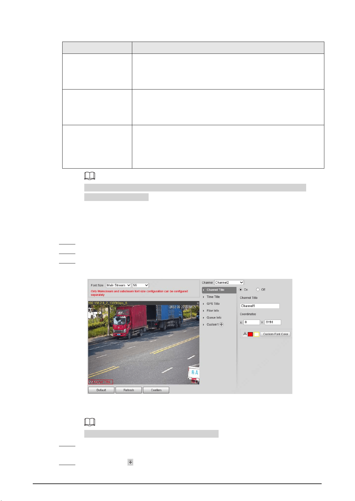
Step 3 Click
Channel Title
, and then select
On
to enable the corresponding OSD type.
Figure 4-34 Video OSD
The Device supports adding information such as the channel, time, GPS, flow, queue and
customized content as OSD.
In this section,
Channel Title
is used as an example.
Step 4 Set the channel title, coordinates and the font color of the content.
You can also drag the OSD box on the image to change the position of channel title.
Step 5 (Optional) Click next to
Custom1
to add more customized OSD information.
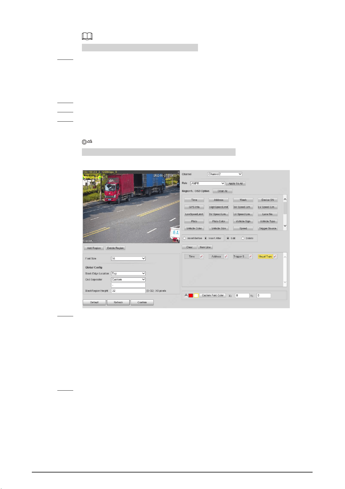
34
The system supports up to 5 customized OSD.
Step 6 Click
Confirm
.
4.5.1.2.5 Setting Snapshot OSD
You can set the OSD information of snapshots.
Step 1 Select
Setting
>
ITC
>
Composition & OSD
>
Snapshot OSD
.
Step 2 Select a channel.
Step 3 Move the image title box to set its position on the snapshot, or manually enter coordinates
into the X/Y box at the lower-right corner of the page.
Click
Add Region
to add more OSD regions on the snapshot.
Figure 4-35 Snapshot OSD
Step 4 Set the font of the OSD information.
1) Select a font size from the list and set the font color at the lower-right corner.
Click
Custom Font Color
to select from more colors.
2) Select
Black Edge Location
and
Osd Seperator
, and then set
BlackRegion Height
.
●
Black Edge Location
: Select the location of the black edge on the image where the
OSD content displays.
●
Osd Seperator
: The separator of the OSD content. Select
Custom
, and then you can
enter a custom separator as needed.
Step 5 Select a channel and a rule to apply the OSD information, and then set the OSD options.
Click
Apply to All
to apply the current OSD configuration to snapshots taken based on all
the rules.

35
Table 4-18 Snapshot OSD description
Parameter Description
Insert Before
Select an OSD option, click
Insert Before
, and then select other OSD
options. The new OSD options will be displayed before the original
OSD option.
Insert After
Select an OSD option, click
Insert After
, and then select other OSD
options. The new OSD option will be displayed after the original OSD
option.
Edit
Select
Edit
, and then click to modify the prefix, suffix, content, and
separator of the corresponding OSD option.
Delete
Select
Delete
, and then click to delete the corresponding OSD
option.
Clear/Clear All Delete all the OSD information.
New Line
After selecting some OSD information, click
New Line
, and the OSD
information inserted after
NewLine
will be displayed in a new line on
the snapshot.
Step 6 Click
Confirm
.
4.5.1.3 Transfer Offline
Enable transfer offline, and the Device will continue to upload the pictures captured during the
offline period to the platform when the Device reconnected to the platform after disconnection.
Step 1 Select
Setting
>
ITC
>
Transfer Offline
.
Step 2 Select
Transfer Offline
to enable this function.
Figure 4-36 Transfer offline
Step 3 Configure parameters.
Table 4-19 Transfer offline parameters
Parameter Description
Type
Select the platform identification type.
●
IP: The system identifies the upload platform through IP address.
●
MAC: The system identifies the upload platform through MAC address.
Platform
Select a platform for transfer. Click
Browse
to search for the current online
platforms.
IP/MAC
address
Enter IP/MAC address.
●
When IP is selected, enter the IP address of the platform for transfer.
●
When MAC is selected, enter the MAC address of the platform for transfer.

36
Parameter Description
Enable
Visualization
Enable visualization to display platform label and upload time on the
corresponding vehicle data list.
Step 4 Click
Confirm
.
Step 5 Click the
Manual Upload
tab, select a target platform and enter its IP address, select a
channel, picture type and time period to upload snapshots taken during the set period to
the specified platform.
Figure 4-37 Manual upload
Step 6 Click
Start Upload
.
During the upload, click
End Upload
to stop uploading.
4.5.1.4 Allowlist and Blocklist
Set the allowlist and blocklist of vehicles. Linked actions will be triggered when vehicles on the lists
are detected.
●
Allowlist: When vehicles on the allowlist are detected, the Device discards the captured vehicle
violation pictures without any processing.
●
Blocklist: When vehicles on the blocklist are detected, the Device triggers linked actions.
4.5.1.4.1 Setting Allowlist
You can set the allowlist of plate numbers. When vehicles in the allowlist are detected, the Device
discards the captured vehicle violation pictures without any processing.
Procedure
Step 1 Select
Setting
>
ITC
>
Blocklist and Allowlist
>
Allowlist
.
Step 2 Add an allowlist.
●
Add one by one.
1. Click
Add
.
2. Set filter conditions and details.

37
Figure 4-38 Add an allowlist
3. Click
Save
.
Select
Continue Adding
, and click
Save
to save the added allowlist information
and add more.
Figure 4-39 Allowlist
●
Add in batches
1. Click
Export
to download and fill in the allowlist template.
For details, see "Appendix 1 Reference for Filling in Allowlist and Blocklist Template"
for how to fill in the corresponding number of plate color, plate type, vehicle color,
and vehicle type.
Table 4-20 Allowlist import table
Begin Time
Cancel
Time
Owner Of
Car
Plate
Color
Plate
Number
Vehicle
Color
Vehicle
Type
2019/5/15
00:00
2019/5/15
23:59
Zhang San 1
Zhejiang
A****
A 1
2. Click
Browse
, and then select the allowlist table you want to import.
3. Click
Import
to import the allowlist table, and then the
Imported Successfully
page is displayed.

38
Related Operations
●
Enter a several-digit field in the plate number, and click
Search
to search for plate numbers
containing this field in the allowlist.
●
Click to modify allowlist parameters.
●
Click to delete a single allowlist.
●
Click
Export
, and then select encryption if needed and then follow the prompts to save the
allowlist.
●
Click
Clear All
to delete all allowlists.
4.5.1.4.2 Setting Blocklist
Set the blocklist of plate numbers. When vehicles in the blocklist are detected, the Device triggers
the actions linked with the alarm.
Select
Setting
>
ITC
>
Blocklist and Allowlist
>
Blocklist
. The setting of blocklist is similar to that of
allowlist. For details, see "4.5.1.4.1 Setting Allowlist".
4.5.1.5 Traffic Flow
You can search for traffic flow data and view the real-time traffic flow.
Step 1 Select
Setting
>
ITC
>
Traffic Flow
>
Flow Query
.
Step 2 Set the time period and select a channel, and then click
Search
.
Select a record, and you can view the details at the bottom.
●
Click
Backup
to save the results.
●
Click
Clear
to delete all information.
●
Switch to other pages during backup, and the backup will stop.
●
Clear
refers to delete all data from the database.
Figure 4-40 Search for traffic flow data
Step 3 Click the
Flow Data
tab to view the flow data of the corresponding channel in real time.
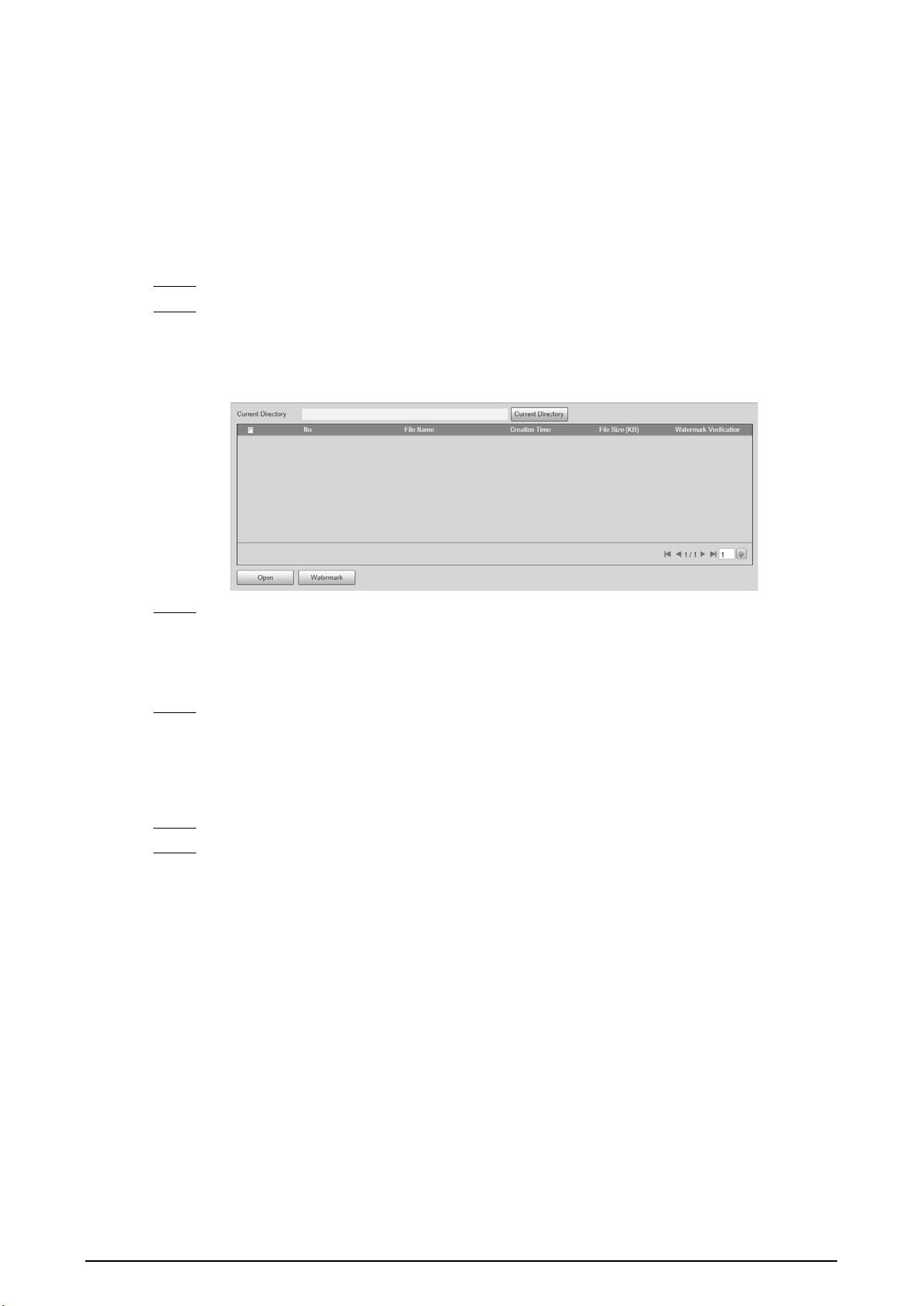
39
4.5.1.6 Watermark Verification
You can verify whether the local pictures and videos were tampered with by checking the
watermark.
4.5.1.6.1 Picture Verification
You can verify whether the local pictures were tampered with.
Step 1 Select
Setting
>
ITC
>
Watermark Verification
>
Picture
.
Step 2 Click
Current Directory
, select the folder where the picture to be verified is located, and
then click
OK
.
All pictures in this folder directory are automatically displayed.
Figure 4-41 Picture watermark verification
Step 3 Select one or more pictures to be verified from the list, and then click
Watermark
. Check
the verification results on the right side of the list.
●
When the result is
Error
, the picture is tampered.
●
When the result is
Normal
, the picture is not tampered.
Step 4 (Optional) Click
Open
to open the selected picture.
4.5.1.6.2 Video Verification
Verify whether the local records were tampered with.
Step 1 Select
Setting
>
ITC
>
Watermark Verification
>
Video
.
Step 2 Click
Browse
, select the record to be verified through the file path, and then click
Watermark
to check the verification results.
●
If the video is verified to be authentic, the watermark you set is displayed next to
Normal Watermark
.
●
If the video is tampered, you can check the details next to
Tampered Watermark
.

40
Figure 4-42 Video
4.5.2 Network Settings
You can set the network parameters of the Device.
4.5.2.1 TCP/IP
You can set the IP address, DNS server and other parameters of the Device to make sure that the
Device can connect to other devices on the network.
Step 1 Select
Setting
>
Network
>
TCP/IP
.
Figure 4-43 TCP/IP
Step 2 Configure parameters.
Table 4-21 TCP/IP parameters
Parameter Description
Host Name
Set the name of the current host, with a maximum length of 15
characters.
Ethernet Card
Dual Ethernet cards are supported. Select an Ethernet card, and then
click
Set as Default
to set it to the default.
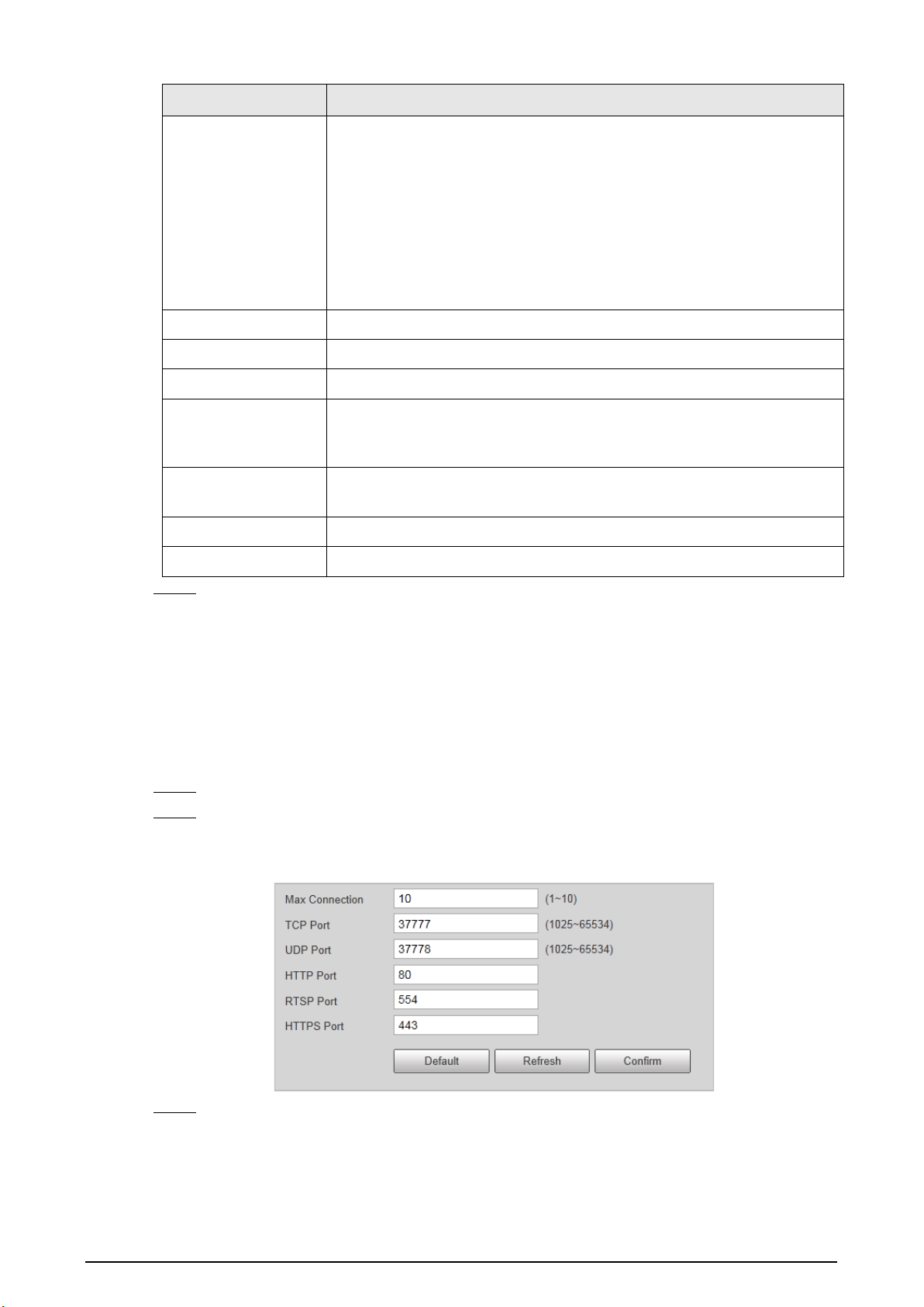
41
Parameter Description
Mode
Select a network mode.
●
DHCP mode: Automatically obtains the IP address. The
IP Address
,
Subnet Mask
, and
Default Gateway
cannot be set when DHCP is
enabled. You can check the current IP address regardless if the DHCP
takes effect.
●
Static mode: Manually set
IP Address
,
Subnet Mask
, and
Default
Gateway
, and then click
Confirm
. The webpage will automatically
go to the login page of the set IP address.
MAC Address MAC address of the host, which cannot be modified.
IP Version Only IPv4 is supported.
Address Enter IP address.
Subnet Mask
Set a subnet mask as needed. The subnet prefix is a number in the range
from 1 through 255. The subnet prefix identifies a specific network link
and usually contains a hierarchical structure.
Default Gateway
Set a default gateway on the same network segment as the IP address as
needed.
Preferred DNS IP address of DNS.
Alternate DNS IP address of the alternate DNS.
Step 3 Click
Confirm
.
4.5.2.2 Port
4.5.2.2.1 Port
You can set the information of the connected ports to access the Device through different protocols
and configuration tools.
Step 1 Select
Setting
>
Network
>
Port
>
Port
.
Step 2 Set the maximum number of clients accessing the Device at the same time (such as
webpage and platform client) and each port value of the Device.
Figure 4-44 Port
Step 3 Click
Confirm
.
4.5.2.2.2 ONVIF
Enable ONVIF, and then network video products produced by different manufacturers can
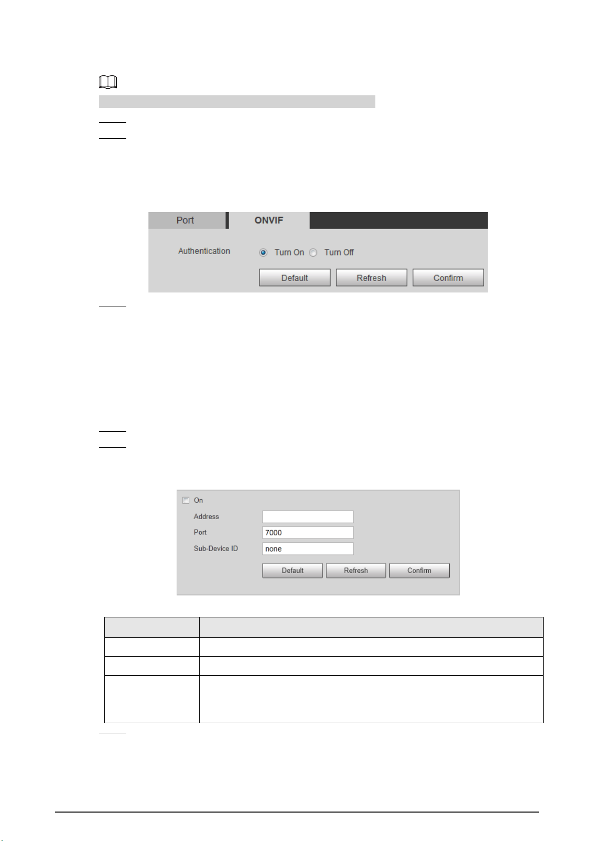
42
communicate with each other.
Login verification is required by default when ONVIF is enabled.
Step 1 Select
Setting
>
Network
>
Port
>
ONVIF
.
Step 2 Select
Turn On
or
Turn Off
as needed.
●
By turning on ONVIF authentication, login username and password are required when
logging in through ONVIF.
●
Login verification is not required when turning off ONVIF authentication.
Figure 4-45 ONVIF
Step 3 Click
Confirm
.
4.5.2.3 Auto Registration
Configure automatic registration, and the current device location will be reported to the server
specified by the user when the Device is connected to internet, so that the client software can use
the server to access the Device, and the server can perform operations such as live view, monitoring,
and configuration of the parameters of the Device.
Step 1 Select
Setting
>
Network
>
Auto Register
.
Step 2 Select
On
to enable automatic registration, and then enter the address, port, and sub-
device ID.
Figure 4-46 Auto registration
Table 4-22 Auto register parameters
Parameter Description
Address Server IP address or server domain that you want to register to.
Port Port of the server for auto register.
Sub-Device ID
ID of the automatically registered device assigned by the server.
Ensure that the ID of the automatically connected device is unique during
configuration.
Step 3 Click
Confirm
.
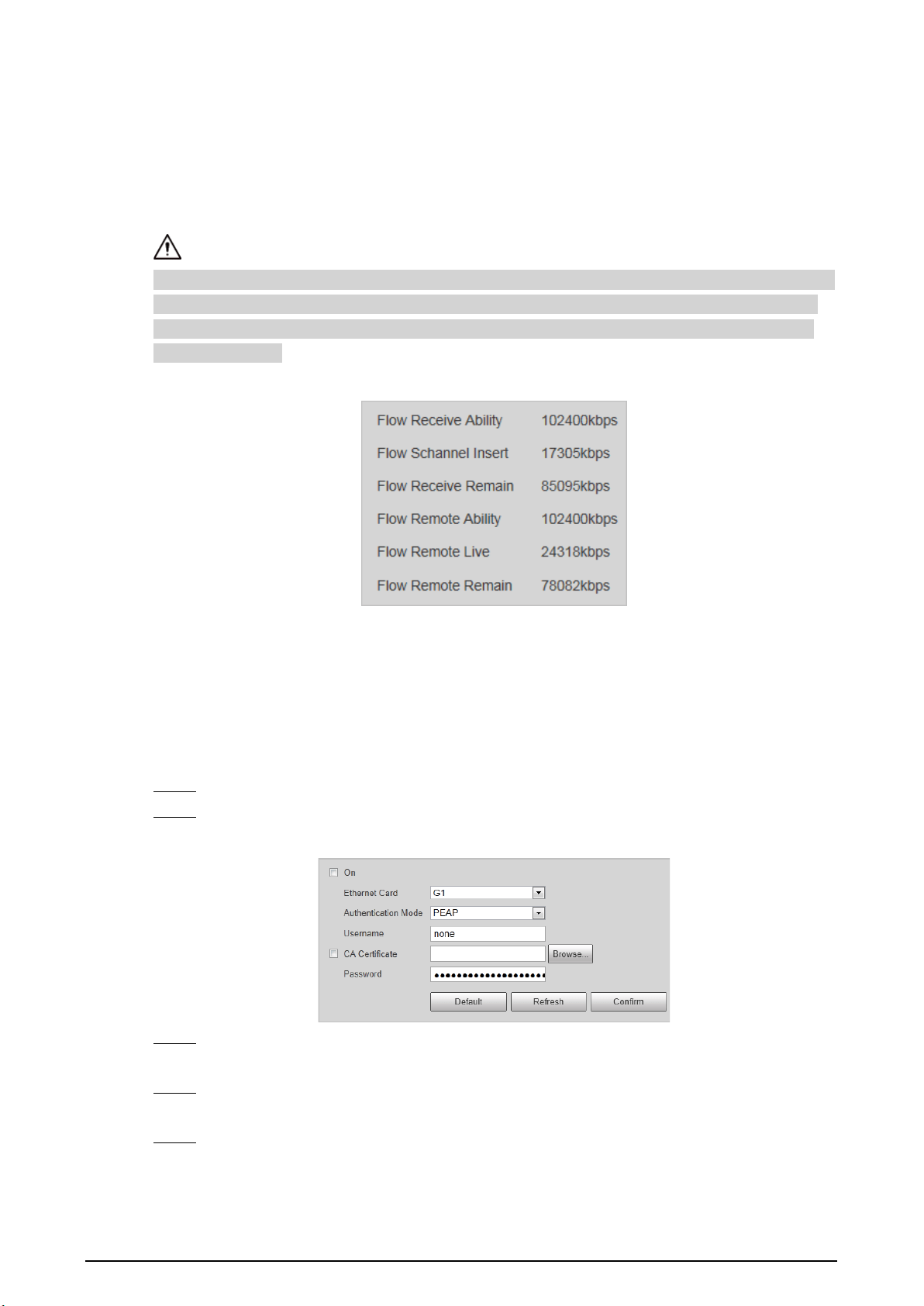
43
4.5.2.4 Flow Statistics
You can view the flow state of the Device, including flow receive ability, flow channel insert, flow
receive remain, flow remote ability, flow remote live, and flow remote remain. Technicians can
troubleshoot network problems according to the statistical data.
Select
Setting
>
Network
>
Flow Statistics
>
Flow Statistics
to view flow statistics.
When
Flow Receive Remain
and
Flow Remote Remain
are negative numbers (in red), it means that
these items have exceeded device performance limits, resulting in possible loss of some data and
other problems. You can reduce the stream size, picture quality, or number of access channels to
solve this problem.
Figure 4-47 Flow statistics
4.5.2.5 IEEE802
IEEE802 is a port-based access control and authentication protocol, which can restrict unauthorized
devices or users from accessing the LAN through the access port. When the switch in the network is
configured with IEEE802, the Device also needs to be set to IEEE802, otherwise users cannot access
the Device through the network.
Step 1 Select
Setting
>
Network
>
IEEE802
.
Step 2 Select
On
, and then select an Ethernet card. The IEEE802 protocol of the NIC is enabled.
Figure 4-48 IEEE802
Step 3 Leave the
Authentication Mode
as default, and then enter the username and password
for authentication. The username must be the one authorized on the server side.
Step 4 Select
CA Certificate
, click
Browse
to select the CA certificate from local computer.
Contact technical support to obtain the CA certificate.
Step 5 Click
Confirm
.
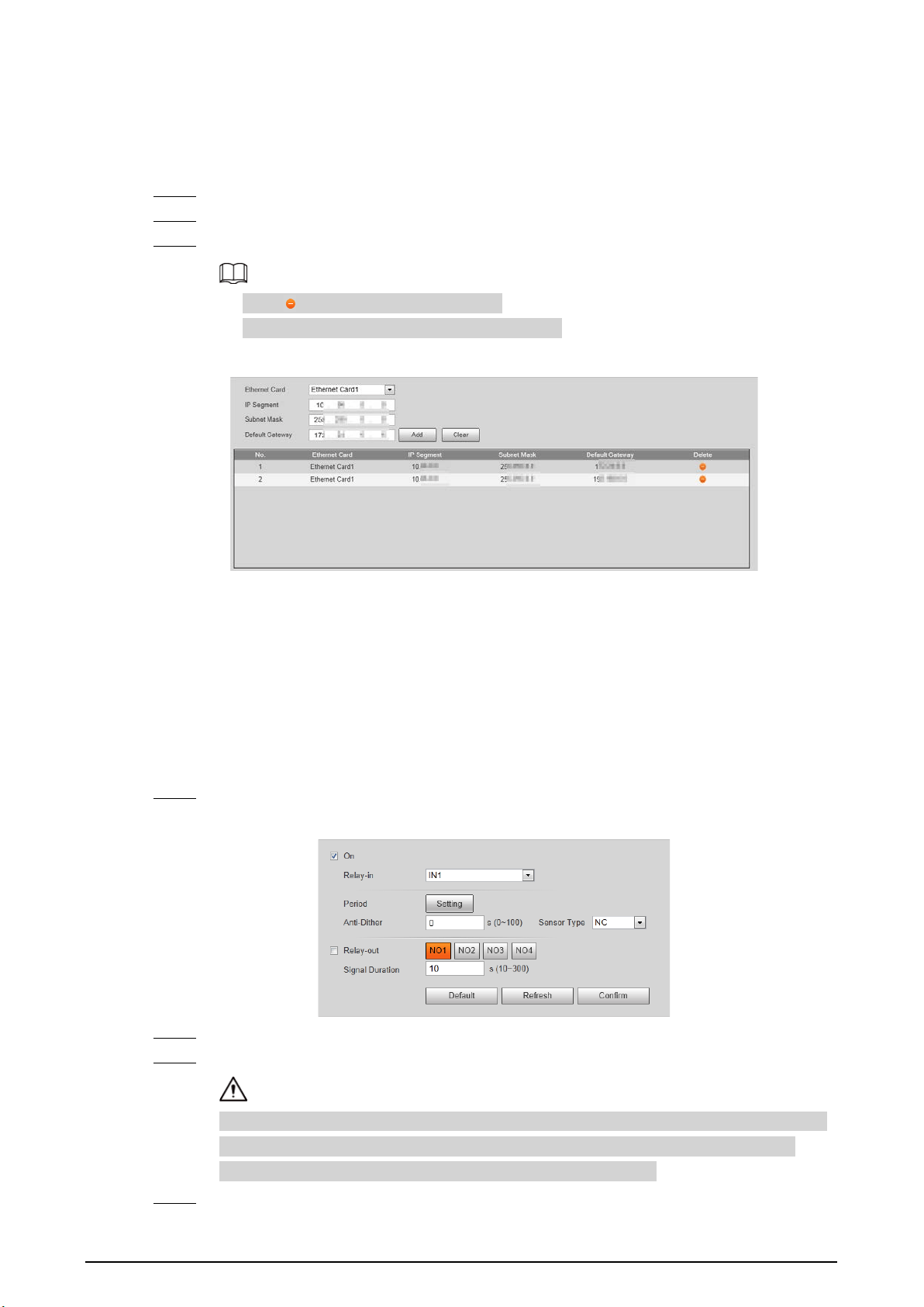
44
4.5.2.6 Routing Settings
The Device supports configuring routings for dual NICs, and accessing gateways of target network
segments.
Step 1 Select
Setting
>
Network
>
Routing Settings
.
Step 2 Select Ethernet card and enter IP segment, subnet mask and default gateway.
Step 3 Click
Add
,
Save Succeeded
appears at the bottom and the routing is added to the list.
●
Click to delete routing one by one.
●
Click
Clear
to quickly delete all added routings.
Figure 4-49 Routing settings
4.5.3 Event Management
4.5.3.1 Setting Relay Activation
Set the input and output channel of alarms on the Device, and then when an alarm is triggered, the
Device outputs the signal to the external device connected to the corresponding output channel,
such as a buzzer.
Step 1 Select
Setting
>
Event
>
Alarm
>
Relay Activation
.
Figure 4-50 Relay activation
Step 2 Select
On
to enable the relay-in for the current channel.
Step 3 Select the relay-in channel.
The settings in the subsequent steps are based on the current channel number. They will
take effect after you click
Confirm
. If you switch the channel number before clicking
Confirm
, all settings for the current channel will not be effective.
Step 4 Set the relay-in arming and disarming periods.
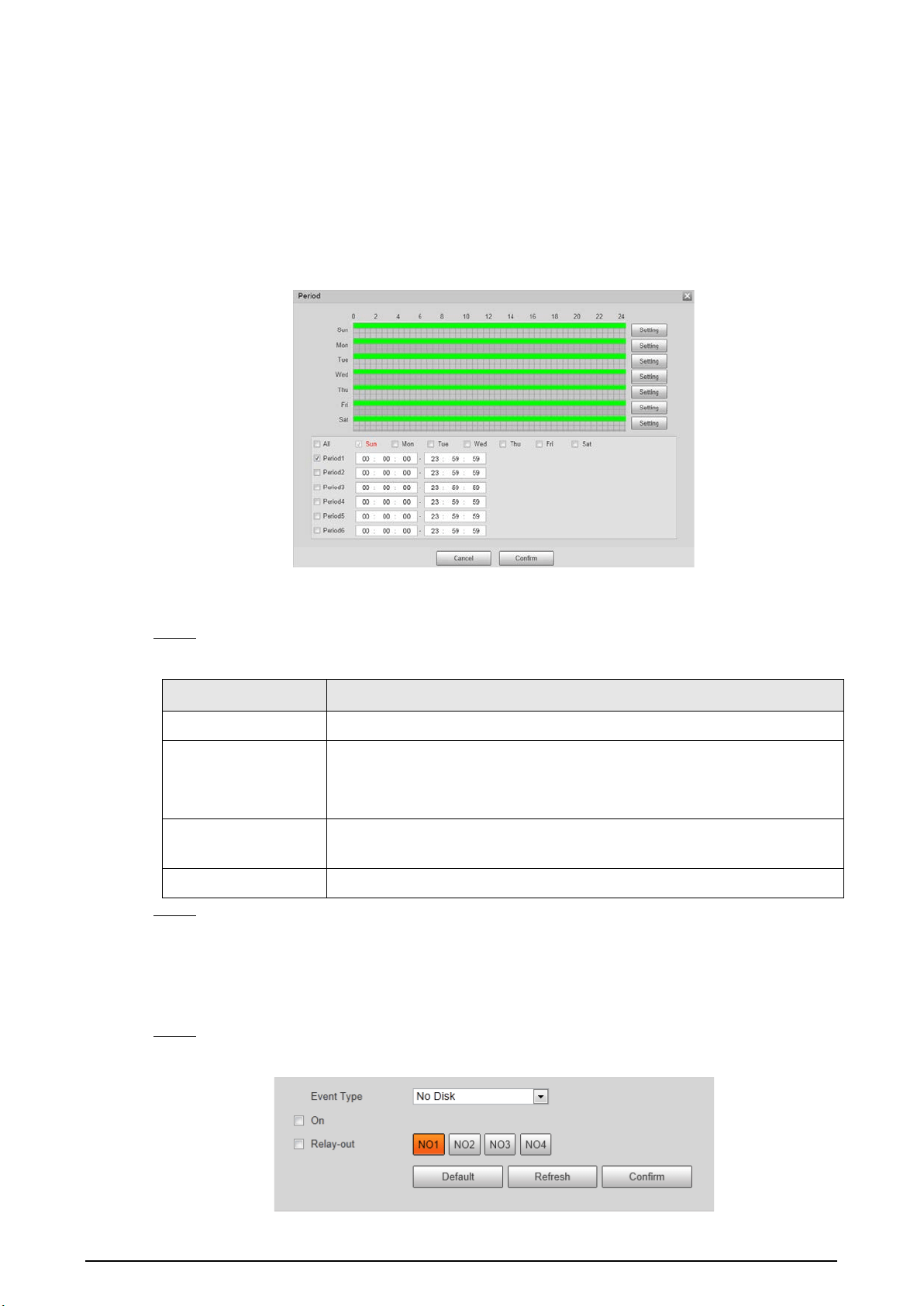
45
The Device outputs alarm signals during armed periods.
1) Click
Setting
.
2) Set the arming and disarming periods.
●
Method 1: Press and hold the left mouse button, and directly drag to set the period
on the timeline corresponding to Sunday to Saturday.
●
Method 2: Click
Setting
corresponding to Sunday to Saturday, and then select and
set the arming and disarming periods. You can set up to six periods.
Figure 4-51 Period
3) Repeat the earlier steps to set the periods corresponding to other days.
4) Click
Confirm
.
Step 5 Set other parameters.
Table 4-23 Relay activation parameters
Parameter Description
Anti-Dither Set the anti-dither duration to filter out false alarms.
Sensor Type
Select sensor type according to the connected relay-in device.
●
Normally open: Effective for low level.
●
Normally closed: Effective for high level.
Relay-out
Optocoupler output. When enabled, the corresponding external device
can be activated after an alarm goes off.
Signal Duration Set the duration of the output signal.
Step 6 Click
Confirm
.
4.5.3.2 Abnormality
Set relay-out for disk abnormal, illegal access, and security exception.
Step 1 Select
Setting
>
Event
>
Alarm
>
Abnormality
.
Figure 4-52 Disk abnormal
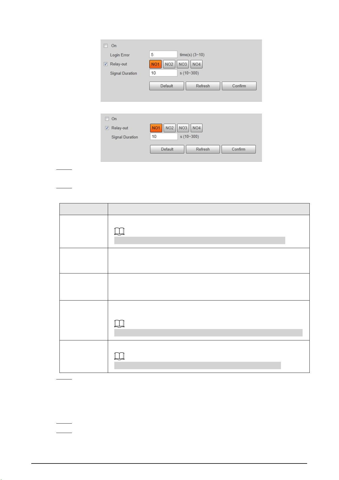
46
Figure 4-53 Illegal access
Figure 4-54 Security exception
Step 2 Select
On
to enable you to handle the corresponding abnormal events.
Event Type
is
required in
Disk Abnormal
.
Step 3 Configure parameters.
Table 4-24 Abnormality parameters
Parameter Description
Event Type
Select an event type. You can select
No Disk
or
Inadequate Disk Space
.
The setting is required only when the
Disk Abnormal
tab is selected.
Relay-out
Select the checkbox to enable
Relay-out
, and then select an alarm output
channel. When an error occurs, the corresponding alarm output device will
receive the signal and send an alarm.
Signal Duration
After the alarm ends, the relay-out will be extended for a period of time
before stopping.
The duration ranges from 10 s to 300 s.
Available
Capacity
When the remaining capacity of the HDD is lower than this value, an alarm is
triggered.
The setting is required only when the event type is
Inadequate Disk Space
.
Number of
login errors
allowed
When the number of login errors exceeds this value, an alarm is triggered.
The setting is required only when the
Illegal Access
tab is selected.
Step 4 Click
Confirm
.
4.5.3.3 Testing Alarm I/O Output
Set alarm output parameters on the I/O page to test whether the alarm output is normal.
Step 1 Select
Setting
>
Event
>
Alarm I/O
.
Step 2 Select a channel number to enable alarm output.
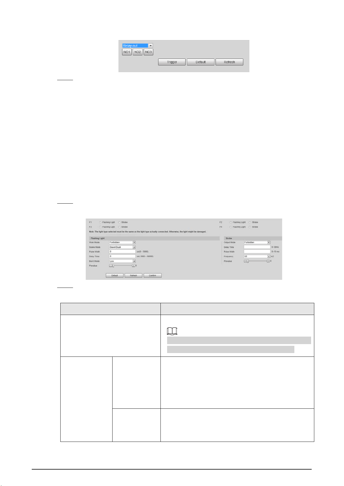
47
Figure 4-55 Alarm I/O
Step 3 Click
Trigger
to check whether the external alarm device normally triggers alarms.
4.5.4 Peripheral
4.5.4.1 Extra Device Status
Select
Setting
>
Peripheral
>
Peripheral
>
Extra Device Status
, and then you can view the
information of the connected external devices.
4.5.4.2 Light Configuration
You can configure the work mode of the flashing lights and strobes connected through RS-485 to
the Camera.
Step 1 Select
Setting
>
Peripheral
>
Peripheral
>
Light Config
.
Figure 4-56 Light config
Step 2 Configure parameters.
Table 4-25 Illuminator parameter description
Parameter Description
F1/2/3/4
Select the light type connected to each port.
The light type must be the same as the actual connected
light type. Otherwise, the light might be damaged.
Flashing Light
Work Mode
●
Forbidden
: The light is normally off.
●
Always
: The light is normally on.
●
Default
: Configure the preset value of brightness. If
the ambient brightness is lower, the light
automatically turns on; if higher, the light
automatically turns off.
Scene Mode
Select the scene mode for the flashing light from
Dawn/Dusk
,
Daytime
and
Night
, indicating different
brightness of the light which suits the environment the
best.

48
Parameter Description
Pulse Width
Configure the pulse width of flashing light. The higher
the value, the brighter the light.
Delay Time
Configure the delay time of the light to keep the
snapshot in sync with the flash.
Burst Mode
You can select the level that triggers the flashing light.
Currently, only
Low
level is supported.
Prevalue
When setting
Work Mode
to
Default
, you need to set the
brightness prevalue.
Strobe
Output Mode
Same as
Work Mode
of flashing light.
Frequency Set the frequency of the strobe.
Step 3 Click
Confirm
.
The light type in this section is for reference only, and might differ from the actual model.
4.5.5 Storage Management
Configure the storage method and location of pictures and records.
4.5.5.1 Storage
4.5.5.1.1 Local Storage
You can set the storage ratio of locally stored pictures and records, view the storage state, and set
the HDD state.
Step 1 Select
Setting
>
Storage
>
Local Storage
>
Local Storage
.
Figure 4-57 Local Storage
Step 2 Select the container according to the storage ratio of pictures and records.
●
The record container is automatically set with the change of the picture container.
●
When the picture container is set to 0%, pictures cannot be stored. When the picture
container is set to 100%, records cannot be stored.
Step 3 Click
Read Only
or
Read & Write
to set the read and write access to the HDDs of the
Device.
Step 4 Click
Confirm
, and then restart the Device.

49
If the HDDs are full, back up the data as required, and then click
Format
to clear the HDD.
4.5.5.1.2 Smart Info
SMART (Self-Monitoring Analysis and Reporting Technology) is used to display automatic HDD
detection results, so you can discover and predict possible HDD problems in time.
When the health state is
Failure
, replace the HDD in time to avoid real-time data loss.
Step 1 Select
Setting
>
Storage
>
Local Storage
>
Smart Info
.
Step 2 Select
Disk No.
to check the related information and health state of the disk.
Figure 4-58 Smart info
4.5.5.2 FTP Storage
Back up pictures to the FTP server for later viewing.
Step 1 Select
Setting
>
Storage
>
FTP Storage
.

50
Figure 4-59 FTP storage
Step 2 Click
FTP Storage
.
Step 3 (Optional) Set
FTP Custom Naming
as required. Click to modify the corresponding
name.
Step 4 Select a server tab, and then select
On
to enable the storage function of this server.
Step 5 Configure parameters.
Table 4-26 FTP storage parameters
Parameter Description
Protocol Select a protocol. SFTP is recommended.
Connect mode
●
Short-lived Link
: Connects with the FTP server when uploading each
image and disconnect after upload completes.
●
Long-lived Link
: The device stays connected with the FTP server.
Encode Type
Select an encode mode.
●
UTF-8
: International universal font library, with various languages.
●
GB2312
: National standard font library, only with Chinese characters
and some common foreign languages.
Test
Click
test
to test whether the FTP server is successfully connected, and the
corresponding test file will be generated according to the selected encode
mode.
Address The IP address of the FTP server.
Port The port number of the FTP server, 22 by default.
Username The username of the FTP server.
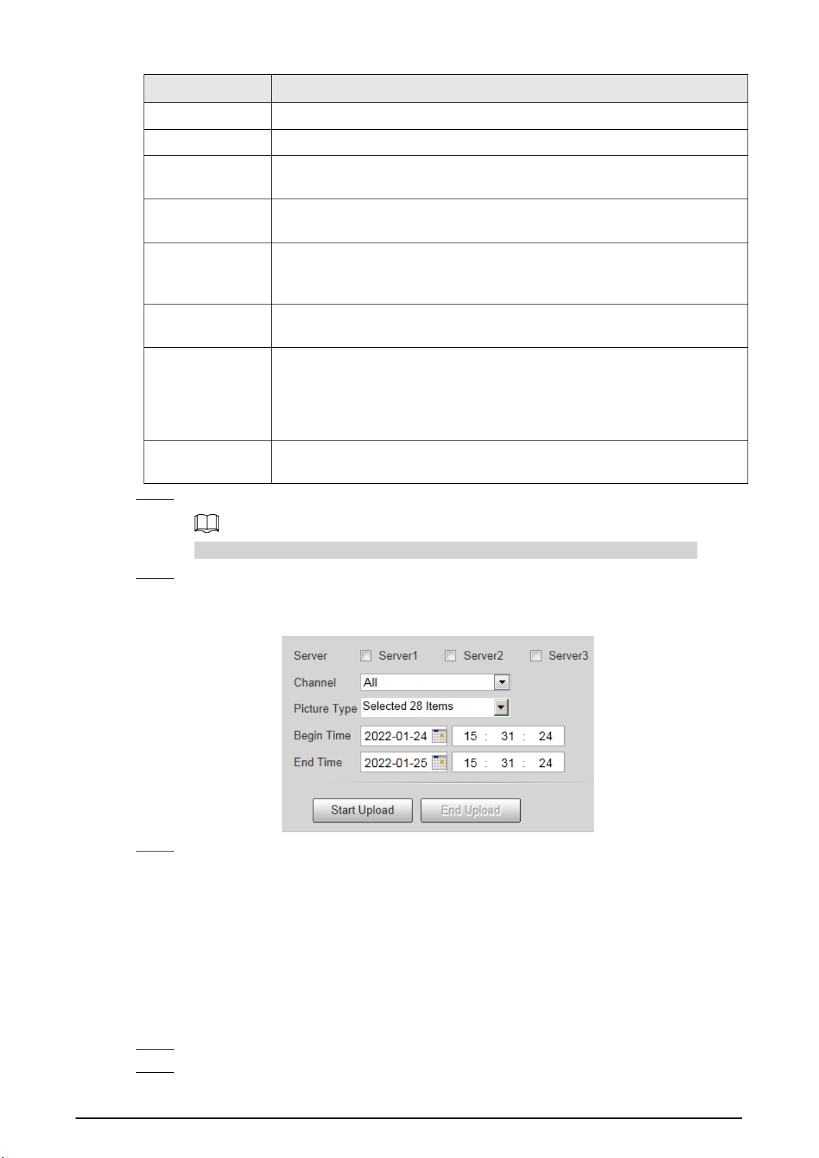
51
Parameter Description
Password The password of the FTP server.
Remote Directory The file storage path of the FTP server.
Related Video
Time
Set the length of the video captured during a period before and after the
time of event, in seconds.
Server Timeout
Duration
Set the timeout duration of waiting for server response.
Enable Offline
Transfer
Select the checkbox. When the Device is disconnected from the FTP server
and reconnected to it, the pictures during the offline period will continue to
be uploaded.
Upload Type
Select the original picture, mosaic picture, plate picture, related record,
corresponding to the violation types to be uploaded to this server.
FTP Named
Set the naming method of pictures and related videos respectively.
●
Help
: The naming format window is prompted, on which you can select,
insert and delete naming items. You can add up to 76 items.
●
Restore
: Restore the default naming rules.
Support Multi Ftp
Name
Select the checkbox, and three FTP naming rules can be separately
configured.
Step 6 Click
Confirm
.
You can configure three FTP servers and repeat configuring the same violation type.
Step 7 Click
Manual Upload
tab, select a target server, a channel, picture type and time period to
upload snapshots taken during the set period to the specified server.
Figure 4-60 Manual upload to server
Step 8 Click
Start Upload
.
During the upload, click
End Upload
to stop uploading.
4.5.5.3 Recording
4.5.5.3.1 Record Control
You can set pack duration, record mode of each channel, and the recording method when the disk is
full.
Step 1 Select
Setting
>
Storage
>
Recording
>
Record Control
.
Step 2 Configure record control parameters.

52
Figure 4-61 Record control
Table 4-27 Record control parameters
Parameter Description
Pack
Duration
Set the duration of each record.
Disk Full
Select the recording method when the disk is full.
●
Stop
: If the current disk is full, recording and picture storage will be
stopped.
●
Overwrite
: After the current disk is full, the oldest files will be circularly
overwritten.
Record Mode
Set the record mode of each channel.
●
Main Stream
: Automatic recording in main stream mode according to the
Record Plan
.
●
Sub Stream
: Automatic recording in Sub Stream mode according to the
Record Plan
.
●
Off
: Recording disabled.
●
If
Sub Stream
is selected, enable
Sub Stream
for the camera.
●
If
Off
is selected, videos of the corresponding channel cannot be queried on
the data query page.
●
To set the same record mode for all channels, select the record mode in the
All
area.
Step 3 Click
Confirm
.
4.5.5.3.2 Record Plan
You can set the time and type to enable recording for each channel.
Step 1 Select
Setting
>
Storage
>
Recording
>
Record Plan
.

53
Figure 4-62 Record plan
Step 2 Select a channel to set the record plan.
Step 3 Set the record plan periods. There are two setting methods.
●
Click
Copy
to copy the record plan of the current channel to another channel.
●
Only
Normal
is supported for record type now.
●
Method 1: Press and hold the left mouse button, and directly drag to set the period on
the timeline corresponding to Sunday to Saturday.
●
Method 2: Click
Setting
on the right side of Sunday to Saturday. On the
Setting
page,
select periods and record types, and then click
Confirm
. The
Record Plan
page is
displayed.
Figure 4-63 Record time setting
Step 4 Click
Confirm
.
4.5.5.3.3 Video
You can set the stream parameters of recording on each channel.
Step 1 Select
Setting
>
Storage
>
Recording
>
Video
.

54
Figure 4-64 Video
Step 2 Set parameters for the main stream and sub stream.
Table 4-28 Video parameters description
Parameter Description
Encode Mode Currently it only supports H.264M, H.264H, H.265, and MJPEG.
Resolution
Select the video resolution.
The resolution of sub stream cannot be greater than that of the main stream.
Bit Rate Type
Includes
VBR
, and
CBR
.
Image quality can only be set in VBR mode.
I Frame Interval
Frame or time interval between two I frames. The bigger the interval, the
smaller space taken by the decompressed video. The system default is set
twice as big as frame rate.
Quality Select the video quality when using the sub stream.
Watermark
Settings
Set the watermarks, which will be added into videos of the Camera.
●
Select
Watermark Settings
to enable the watermark adding.
●
Watermark Character
is DigitalCCTV by default.
●
The watermark character can only consist of number, letter, underline,
and maximum length contains 85 characters.
Step 3 Click
Confirm
.
4.5.5.4 Snapshot
Enable snapshot for a channel and set the related recording channel, so the snapshots and related
recordings can be saved.
Make sure the time of both channels are the same.
Step 1 Select
Setting
>
Storage
>
Snapshot
.
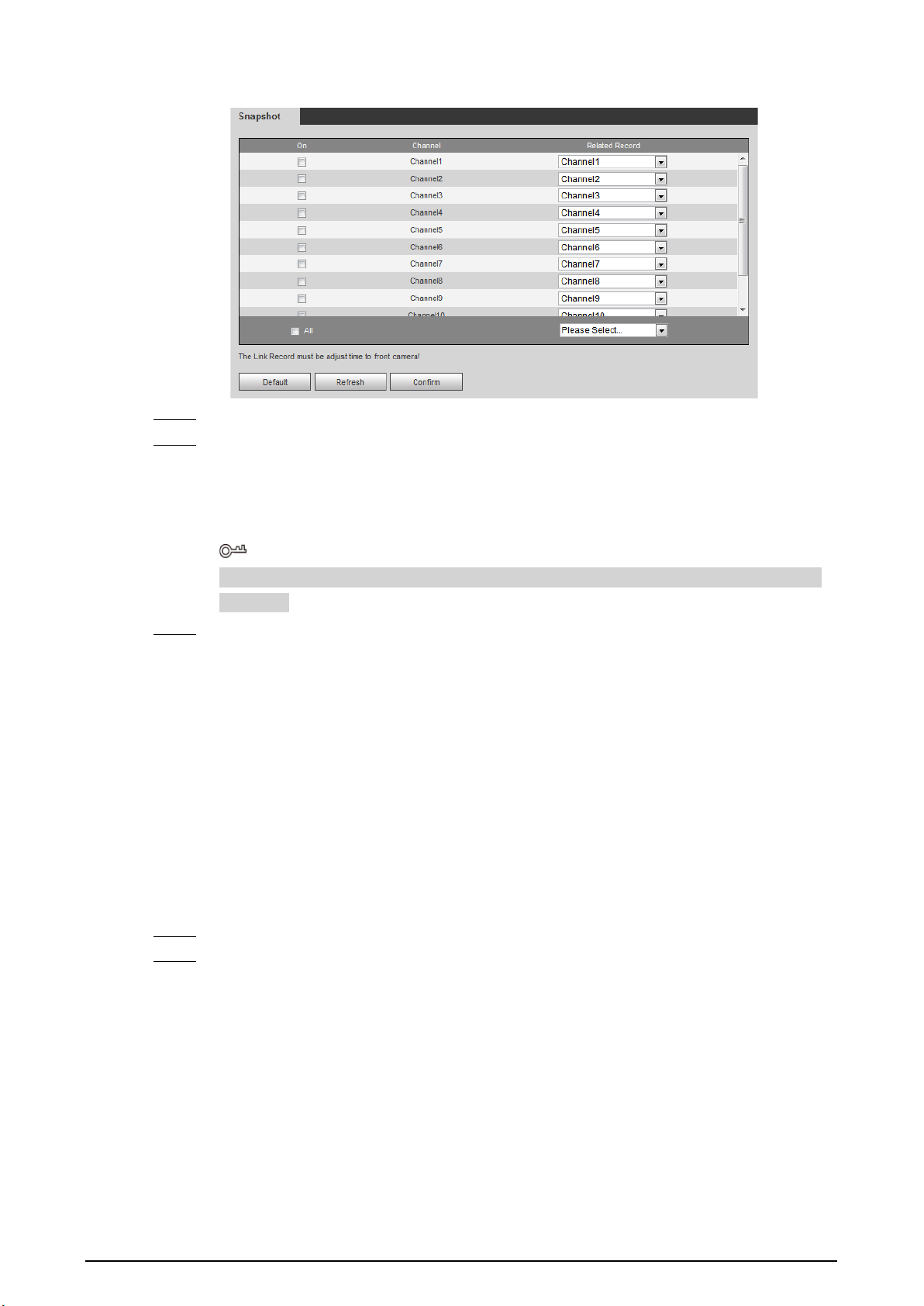
55
Figure 4-65 Snapshot settings
Step 2 Select
On
corresponding to the channel to enable snapshot.
Step 3 Set the related record of each channel.
●
To set recording linkage for each channel separately, select channel number in
Related
Record
.
●
If recording linkage is not required, select
No Link
.
If all channels need to set the same related record, select
All
and set the linked record as
required.
Step 4 Click
Confirm
.
4.5.6 System
4.5.6.1 General
You can configure display language, video standard, and also set the time and time zone of the
Device.
4.5.6.1.1 General Settings
You can configure the Device No., video standard, and more.
Step 1 Select
Setting
>
System
>
General Setup
>
General Setup
.
Step 2 Configure the parameters.
For
Video Standard
,
PAL
and
NTSC
are available.
●
PAL
: Much more common around the world, and can be found in most of Western
Europe, Australia, China, and elsewhere.
●
NTSC
: Mostly limited to North America, parts of South America, Japan, the Philippines.

56
Figure 4-66 General
Step 3 Click
Confirm
.
4.5.6.1.2 Date & Time
You can configure date, time, time zone, and more of the Device.
Step 1 Select
Setting
>
System
>
General Setup
>
Date&Time
.
Step 2 Configure the parameters.
Figure 4-67 Date & time
Table 4-29 Date&time parameters
Parameter Description
Date Format
Select the date format. Three formats are available:
YYYY-MM-DD
,
MM-
DD-YYYY
and
DD-MM-YYYY
.
Time Format
Only
24-Hour
is available.
Time Zone The time zone where the Device locates.
System Time The current time of the Device.
Sync PC
Sync the time of the Device with the time of the computer.
Click
Sync PC
, and settings will immediately take effect.
DST
Select the
DST
(Daylight Saving Time) checkbox, set the
DST Type
by
Date
or by
Week
, and then configure the
Start Time
and
End Time
of
DST.
Enable Select
GPS
or
BeiDou
positioning system.
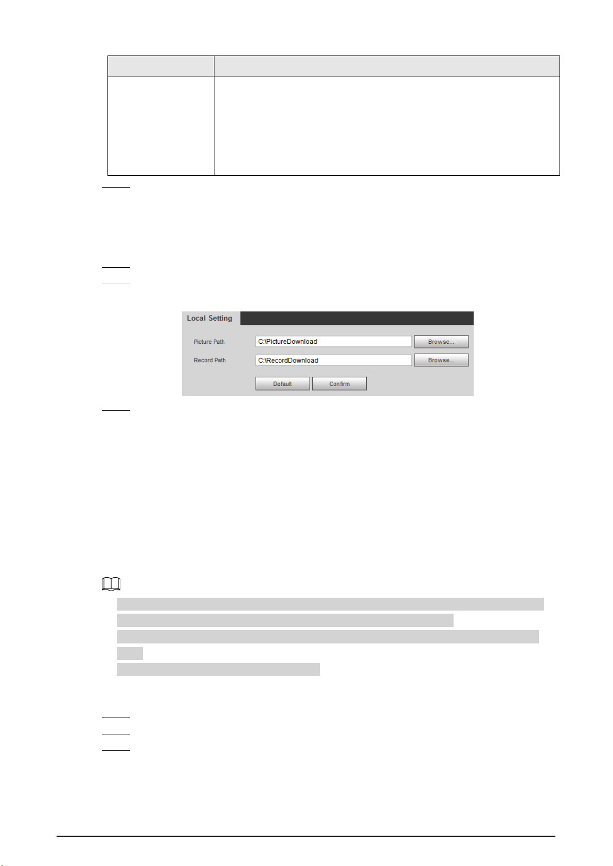
57
Parameter Description
Check Time Mode
Select time synchronization mode.
●
NTP
: Select the checkbox to enable
NTP
(network time protocol) time
synchronization. In this case, you need to set the NTP server IP
address, port, and time synchronization interval.
●
Satellite
: Synchronize the time according to the positioning. In this
case, you need to enable
GPS
or
BeiDou
positioning first.
Step 3 Click
Confirm
.
4.5.6.2 Local Setting
Configure the storage path of snapshots and videos.
Step 1 Select
Setting
>
System
>
Local Setting
.
Step 2 Click
Browse
to select the storage path of snapshots and videos respectively.
Figure 4-68 Local setting
Step 3 Click
Confirm
.
4.5.6.3 Account Management
You can add or delete users and user groups, assign permissions to new users and user groups,
change password, and manage users and user groups.
4.5.6.3.1 Managing Users
You can view user information, add or delete user(s), change user password, assign user permissions,
restrict user login, and more.
●
After the Device is initialized, the admin user generated by default has the highest permission.
The admin user cannot be deleted, and its permissions cannot be changed.
●
Users with
User
permission can change its own password, and change the password of other
users.
●
Users who have logged in cannot be deleted.
Procedure
Step 1 Select
Setting
>
System
>
Account
>
Account
>
Username
.
Step 2 Click
Add User
.
Step 3 Configure the user information including username, password, group name, memo, and
operation permissions.
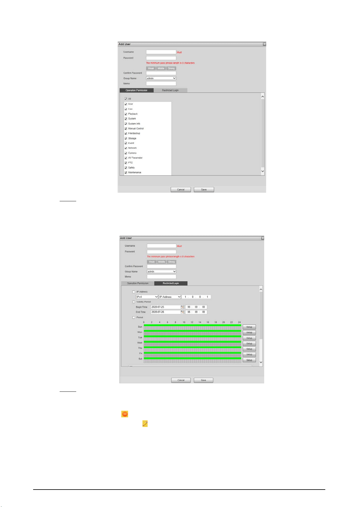
58
Figure 4-69 Add user
Step 4 Set login restrictions (if necessary), and then the restricted IP addresses or IP within the
defined segment will be allowed to log in to the Device during the defined validity period
and time.
Figure 4-70 Configure login restriction
Step 5 Click
Save
.
Related Operations
●
Delete a user: Click to delete the corresponding user. Admin user cannot be deleted.
●
Edit user information: Click corresponding to the user. You can edit the information such as
username, password, email address, group name, and memo. Click
Save
to save the settings.
●
Change password: On the
Modify User
page, select the
Modify Password
checkbox. Enter the
old and new passwords, and confirm password. Click
Save
after configuration.
4.5.6.3.2 Managing User Groups

59
After the Device is initialized, two user groups, admin and user, are generated by default. You can
also add or delete user group(s), and change user group password and permissions.
Step 1 Select
Setting
>
System
>
Account
>
Account
>
Group Name
.
Step 2 Add, modify, and delete user groups.
●
Add a user group
1. Click
Add Group
.
2. Configure the
Group Name
and
Authority
of the group.
Figure 4-71 Add user group
3. Click
Save
.
Click an added user group, and then you can view its permissions.
●
Modify a user group
1. Click .
2. Modify the memo and permissions of the group.
Permission of admin user group cannot be deleted.
3. Click
Save
.
●
Delete a user group
Click to delete the selected user group. Admin and user groups cannot be
deleted.
4.5.6.3.3 ONVIF User
You can view ONVIF user information, add or delete ONVIF users, and change ONVIF user passwords.
Step 1 Select
Setting
>
System
>
Account
>
Onvif User
.
Step 2 Add, modify, and delete an ONVIF user.
●
Add user
1. Click
Add User
.
2. Configure user information such as username, password, and group name.
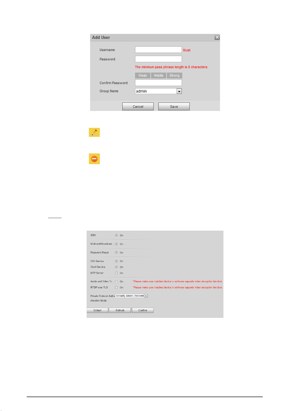
60
Figure 4-72 Add user
3. Click
Save
.
●
Modify user
Click to modify the information such as username, password, and group name.
Group of admin user cannot be modified.
●
Delete user
Click to delete the added user. Admin user cannot be deleted.
4.5.6.4 Safety
4.5.6.4.1 System Service
You can enable multiple system services to secure network safety.
Step 1 Select
Setting
>
System
>
Safety
>
System Service
.
Figure 4-73 System service

61
Step 2 Enable the services as needed.
Table 4-30 Description of system service parameters
Parameter Description
SSH
Secure Shell (SSH) is a cryptographic network protocol for operating
network services securely over an unsecured network. It is a method for
secure remote login, providing secure access for users.
Multicast/Broadcast
Search
Multicast identifies logical groups of computers group members. This
allows a single message to be sent to the group. Broadcast allows all
devices on the same network segment to see the same message.
Password Reset
Enable it so you can reset the password when you forgot your
password.
CGI Service
The service is enabled by default. CGI is the interface between external
applications and the web server, and devices can be accessed through
this protocol.
Onvif Service
The service is enabled by default. It allows network video products
produced by different manufacturers to communicate with each other.
NTP Server Select to enable time synchronization from the NTP server.
Audio and Video
Transmission
Encryption
Select the
Enable
checkbox to enable encryption during audio and
video transmission. Make sure that the matched device or software
supports video decryption function; otherwise, do not enable it.
RTSP over TLS
Enable this function to encrypt stream transmitted through standard
protocol. We recommend you keep the function on.
Private Protocol
Authentication Mode
Keep the recommended configuration.
Step 3 Click
Confirm
.
4.5.6.4.2 HTTPS
Prerequisites
●
For first-time use of HTTPS or after changing device IP address, you need to create server
certificate, and install root certificate.
●
After creating server certificate, and installing root certificate, if you change a computer to log in
to the webpage, then you need to download and install the root certificate again on the new
computer or copy the downloaded root certificate on the new computer, and install it.
On the
HTTPS
page, users can make computer log in normally through HTTPS by creating certificate
or uploading authenticated certificate. It can ensure security of communication data, and provide
guarantee for user information, and device safety through reliable and stable technical approach.
Procedure
Step 1 Create certificate or upload the authenticated certificate.
●
Create a certificate.
1. Select
Setting
>
System
>
Safety
>
HTTPS
.
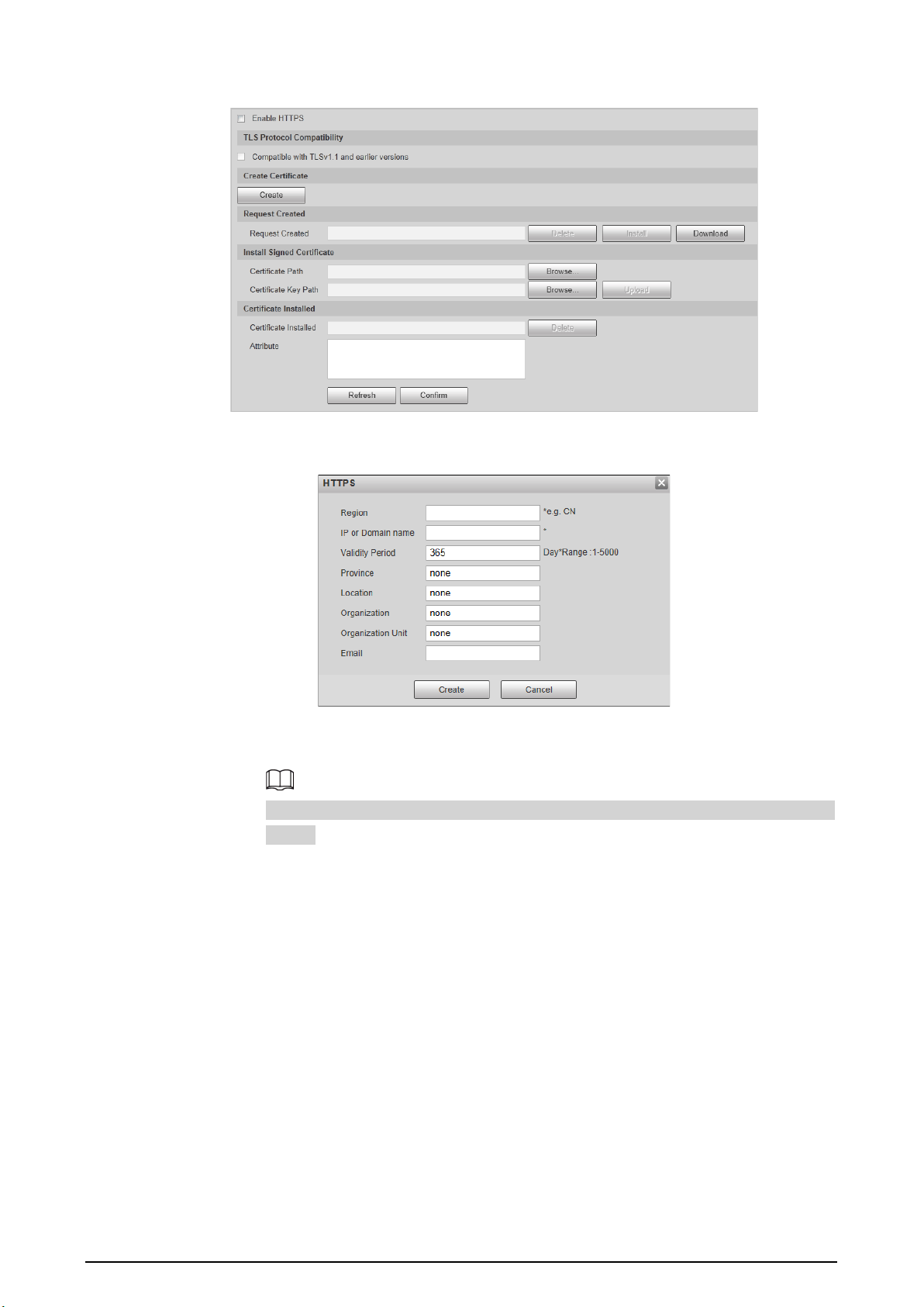
62
Figure 4-74 HTTPS
2. Click
Create
.
Figure 4-75 HTTPS
3. Enter the required information such as region, IP or domain name, and then click
Create
.
The entered
IP or Domain name
must be the same as the IP or domain name of the
Device.
4. Click
Install
under
Request Created
, and then click
Download
to download root
certificate.
The system pops up
Save As
dialog box, select storage path, and then click
Save
.
5. Double-click the RootCert.cer icon.
6. Click
Install Certificate…
.

63
Figure 4-76 Install certificate
7. Click
Next
.
Figure 4-77 Certificate store
8. Click
Next
.

64
Figure 4-78 Completing certificate import wizard
9. Click
Finish
.
Figure 4-79 Security warning
10. Click
Yes
, and then click
OK
on the pop-up window.
●
Install a signed certificate.
1. Select
Setting Safety
>
System
>
Safety
>
HTTPS
.
2. Select
Enable HTTPS
, and
Compatible with TLSv1.1 and earlier versions
.
3. Click
Browse
to upload the signed certificate, and certificate key, and then click
Upload
.
4. To install the root certificate, see operation steps from 4 to 10 in
Create Certificate
.
Step 2 Select
Enable HTTPS
, and click
Confirm
.
The configuration takes effect until the Camera restarts.
Step 3 Use HTTPS to log in to the Camera.
1. Enter https://xx.xx.xx.xx in the browser.
xx.xx.xx.xx is the Camera IP address or domain name.
2. Enter the username, and password to log in to the Camera.

65
4.5.6.4.3 Firewall
Set the security rules to protect the safety of your camera system.
Step 1 Select
Setting
>
System
>
Safety
>
Firewall
.
Figure 4-80 Firewall
Step 2 Select
Rule Type
.
●
Network Access
: Add the IP address to allowlist or blocklist to allow or restrict it to
access corresponding ports of the Camera.
●
PING Prohibited
: IP address of your camera is prohibited from ping. This helps prevent
attempt of accessing your network system without permission.
●
Prevent Semijoin
: Prevents half-open SYN attacks.
Step 3 Select
On
to enable the selected rule type.
Step 4 Click
Confirm
.
4.5.6.5 Default
Select
Setting
>
System
>
Default
, and then you can:
●
Click
Default
to restore most configurations of the Device to default settings (except information
such as IP address, account, and log).
●
Click
Factory Default
, and then enter the correct login password in the pop-up box to restore all
configurations of the Device to default settings, including IP address.
Figure 4-81 Default
4.5.6.6 Import/Export
The system supports exporting the configurations on the webpage to local computer for backup,
and importing the configuration files from local backup for quick configuration or restoration.
Step 1 Select
Setting
>
System
>
Import/Export
.
Figure 4-82 Import/Export
Step 2 Click
Import
or
Export
.

66
●
Import
: Import the configuration files from local backup.
●
Export
: Export the configuration on the webpage to local computer.
The imported and exported files should be in the format of .backup.
Step 3 Select the path of file to import, or the path of file to export.
4.5.6.7 Auto Maintain
The system automatically restarts at 02:00 every day by default. You can also select to automatically
restart the Device at the defined day and time, or manually restart the Device to solve problems such
as stuck images.
Step 1 Select
Setting
>
System
>
Auto Maintain
.
Figure 4-83 Auto maintain
Step 2 Select
Auto Reboot
, and then set the restart time.
Step 3 Select
Auto Delete Old Files
, and then set a time point, and all the old files before this
time will be deleted.
Step 4 (Optional) Click
Manual Reboot
can restart the Camera immediately.
Step 5 Click
Confirm
.
Step 6 Select
Emergency Maintenance
, and then select
On
to enable the function.
Step 7 Click
Save
.
4.5.6.8 System Upgrade
You need to update the system to the latest version to make the Device run properly.
Step 1 Select
Setting
>
System
>
System Upgrade
.
Step 2 Upgrade the system through file upgrade or online upgrade.
●
File Upgrade
1. Click
Import
, and then select the upgrade file in the pop-up dialog box.
2. Click
Upgrade
to start system upgrading.
◇
Visual Module Update (Camera & Illuminator)
: Used to upgrade the camera and
illuminator.
◇
Perceptive Module Update (Radar & Intelligent Traffic Management Terminal)
:
Used to upgrade the radar and terminal.
●
Online Upgrade
◇
Select
Auto-check for updates
, and then click
Confirm
. When a new version is
detected, click
Upgrade Now
, the system starts upgrading.
◇
Click
Manual Check
, and when a new version is detected, click
Upgrade Now
, the
system starts upgrading.

67
Figure 4-84 System upgrade
4.5.7 System Information
You can view information such as version, log, and online user.
4.5.7.1 Version Information
Select
Setup
>
System Info
>
Version
to view information such as device type, software version,
web version, and more.
Versions might vary depending on the different devices.
4.5.7.2 Log
4.5.7.2.1 System Log
You can search for and view logs by the time and type, and backup the logs.
After the number of log records reaches a certain number, the earliest log records will be
overwritten. To prevent critical logs from being overwritten, the system performs log overwriting in
three levels: Low, medium, and high.
●
Low: When the log records reach 896, the earliest log records will be overwritten.
●
Medium: When the log records reach 256, the earliest log records will be overwritten.
●
High: When the log records reach 640, the earliest log records will be overwritten.
Step 1 Select
Setting
>
System Info
>
Log
>
Log
.
Step 2 Set
Start Time
and
End Time
, and then select log type.
Step 3 Click
Search
. You can stop searching according to your need.
●
View: Click a log to view its details.
●
Back up: Click
Backup
to back up the log to local computer in .txt format.
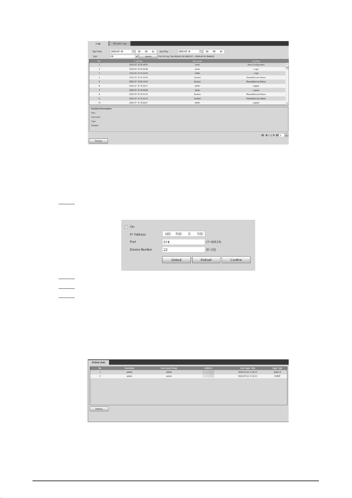
68
Figure 4-85 System log
4.5.7.2.2 Remote Log
Critical logs can be saved to log server. This helps provide important clues to the source of security
incidents. Log server needs to be deployed in advance by technical supports or system
administrator.
Step 1 Select
Setting
>
System Info
>
Log
>
Remote Log
.
Figure 4-86 Remote log
Step 2 Select
On
to enable
Remote Log
.
Step 3 Configure the IP address, port, and device number of remote device.
Step 4 Click
Confirm
.
4.5.7.3 Viewing Online User
Select
Setting
>
System Info
>
Online User
, and then you can view online users’ information, such
as username, user local group, IP address, user login time, and more.
Figure 4-87 Online user
4.5.7.4 Legal Information
Select
Setting
>
System Info
>
Legal Info
to view the Open Source Software Notice.

69
4.6 Alarm
You can select the event type that triggers an alarm, and also configure how to sound the alarm.
Step 1 Select
Alarm
at the upper-right side of the webpage.
Step 2 Select alarm type as needed.
When alarms are triggered, information of the selected alarm type will be displayed at the
right side.
Figure 4-88 Alarm
Step 3 Configure alarm operation and alarm tone.
Table 4-31 Description of alarm parameters
Parameter Description
Operation
Select
Listen Alarm
, and when an alarm is triggered and you are not viewing
the alarm page, will be displayed on the alarm menu bar, and the alarm
information will be automatically recorded. When you click the alarm menu bar,
the icon disappears.
If you are viewing the alarm page when an alarm is triggered, the alarm icon
will not appear, but alarm information will be recorded in the alarm list on the
right.
Alarm Tone
Select
Play Alarm Tone
to enable playing alarm tone, and then click
Choose
to
select the audio file. When an alarm is triggered, the system plays the selected
audio.
Currently, only
.wav
audio file is supported.
4.7 Logout
Click
Logout
at the upper-right side of the webpage to log out. You can enter the username and
password to log in again.

70
Appendix 1 Reference for Filling in Allowlist and
Blocklist Template
Appendix Table 1-1 Plate color number
Plate Color Plate Color No.
Yellow Plate with Black Text 1
Blue Plate with White Text 2
Black Plate with White Text 3
White Plate with Black Text 4
Black 5
Blue 6
Cyan 7
Red 8
Gradient Green 9
White 10
Yellow and Green 11
Yellow 12
Appendix Table 1-2 Vehicle color number
Vehicle Color Vehicle Color No.
White A
Black B
Red C
Yellow D
Gray E
Green F
Blue G
Pink H
Purple I
Brown J
Yellow Green K
Cyan L
Dark Blue M
Dark Brown N
Dark Cyan O
Dark Golden P
Dark Green Q

71
Vehicle Color Vehicle Color No.
Dark Olive R
Dark Orange S
Dark Pink T
Dark Purple U
Dark Red V
Dull Purple W
Dark Yellow X
Deep Sky Blue Y
Others Z
Dark Gray a
Forest Green b
Golden c
Green Yellow d
Chestnut e
Light Rosy f
Olive g
Orange h
Ocean Green i
Silver Gray j
Tomato Red k
White Smoke l
Appendix Table 1-3 Vehicle type number
Vehicle Type Vehicle Type No.
Large Vehicle 1
Small Vehicle 2
Tractor 14
Bus 23
Heavy Truck 24
MPV 25
Light Truck 26
Van 27
Medium Bus 28
Medium Truck 29
Minicar 30
Two-wheeled Vehicle 31
Tank Truck 32

72
Vehicle Type Vehicle Type No.
Public Bus 33
Pickup 34
SUV 35
Sedan 36
SUV-MPV 37
Taxi 38
Tricycle 39
Unknown 40
Ambulance 41
Mixer Truck 42
Construction Truck 43
Fire Truck 44
General 45
Engineering Truck 46
Fuel Tank Truck 47
Police Car 48
Pulverized Material Vehicle 49
Tank Truck 50
Sewage Suction Truck 51
Hazardous Chemicals Truck 52
Sanitation Truck 53

73
Appendix 2 Cybersecurity Recommendations
Mandatory actions to be taken for basic device network security:
1.
Use Strong Passwords
Please refer to the following suggestions to set passwords:
●
The length should not be less than 8 characters.
●
Include at least two types of characters; character types include upper and lower case letters,
numbers and symbols.
●
Do not contain the account name or the account name in reverse order.
●
Do not use continuous characters, such as 123, abc, etc.
●
Do not use overlapped characters, such as 111, aaa, etc.
2.
Update Firmware and Client Software in Time
●
According to the standard procedure in Tech-industry, we recommend to keep your
equipment (such as NVR, DVR, IP camera, etc.) firmware up-to-date to ensure the system is
equipped with the latest security patches and fixes. When the equipment is connected to the
public network, it is recommended to enable the “auto-check for updates” function to obtain
timely information of firmware updates released by the manufacturer.
●
We suggest that you download and use the latest version of client software.
"Nice to have" recommendations to improve your equipment network security:
1.
Physical Protection
We suggest that you perform physical protection to equipment, especially storage devices. For
example, place the equipment in a special computer room and cabinet, and implement well-
done access control permission and key management to prevent unauthorized personnel from
carrying out physical contacts such as damaging hardware, unauthorized connection of
removable equipment (such as USB flash disk, serial port), etc.
2.
Change Passwords Regularly
We suggest that you change passwords regularly to reduce the risk of being guessed or cracked.
3.
Set and Update Passwords Reset Information Timely
The device supports password reset function. Please set up related information for password
reset in time, including the end user’s mailbox and password protection questions. If the
information changes, please modify it in time. When setting password protection questions, it is
suggested not to use those that can be easily guessed.
4.
Enable Account Lock
The account lock feature is enabled by default, and we recommend you to keep it on to
guarantee the account security. If an attacker attempts to log in with the wrong password several
times, the corresponding account and the source IP address will be locked.
5.
Change Default HTTP and Other Service Ports
We suggest you to change default HTTP and other service ports into any set of numbers between
1024–65535, reducing the risk of outsiders being able to guess which ports you are using.
6.
Enable HTTPS
We suggest you to enable HTTPS, so that you visit Web service through a secure communication
channel.

74
7.
MAC Address Binding
We recommend you to bind the IP and MAC address of the gateway to the equipment, thus
reducing the risk of ARP spoofing.
8.
Assign Accounts and Privileges Reasonably
According to business and management requirements, reasonably add users and assign a
minimum set of permissions to them.
9.
Disable Unnecessary Services and Choose Secure Modes
If not needed, it is recommended to turn off some services such as SNMP, SMTP, UPnP, etc., to
reduce risks.
If necessary, it is highly recommended that you use safe modes, including but not limited to the
following services:
●
SNMP: Choose SNMP v3, and set up strong encryption passwords and authentication
passwords.
●
SMTP: Choose TLS to access mailbox server.
●
FTP: Choose SFTP, and set up strong passwords.
●
AP hotspot: Choose WPA2-PSK encryption mode, and set up strong passwords.
10.
Audio and Video Encrypted Transmission
If your audio and video data contents are very important or sensitive, we recommend that you
use encrypted transmission function, to reduce the risk of audio and video data being stolen
during transmission.
Reminder: encrypted transmission will cause some loss in transmission efficiency.
11.
Secure Auditing
●
Check online users: we suggest that you check online users regularly to see if the Device is
logged in without authorization.
●
Check equipment log: By viewing the logs, you can know the IP addresses that were used to
log in to your devices and their key operations.
12.
Network Log
Due to the limited storage capacity of the equipment, the stored log is limited. If you need to
save the log for a long time, it is recommended that you enable the network log function to
ensure that the critical logs are synchronized to the network log server for tracing.
13.
Construct a Safe Network Environment
In order to better ensure the safety of equipment and reduce potential cyber risks, we
recommend:
●
Disable the port mapping function of the router to avoid direct access to the intranet devices
from external network.
●
The network should be partitioned and isolated according to the actual network needs. If
there are no communication requirements between two sub networks, it is suggested to use
VLAN, network GAP and other technologies to partition the network, so as to achieve the
network isolation effect.
●
Establish the 802.1x access authentication system to reduce the risk of unauthorized access to
private networks.
●
Enable IP/MAC address filtering function to limit the range of hosts allowed to access the
Device.
