All-in-one AI Traffic Camera
User's Manual
V1.0.0

User's Manual
I
Foreword
General
This manual introduces the installation, functions and operations of the 16MP All-in-one AI Traffic
Camera (hereinafter referred to as "the Camera"). Read carefully before using the Camera, and keep
the manual safe for future reference.
Safety Instructions
The following signal words might appear in the manual.
Signal Words Meaning
Indicates a high potential hazard which, if not avoided, will result in
death or serious injury.
Indicates a medium or low potential hazard which, if not avoided,
could result in slight or moderate injury.
Indicates a potential risk which, if not avoided, could result in
property damage, data loss, reductions in performance, or
unpredictable results.
Provides methods to help you solve a problem or save time.
Provides additional information as a supplement to the text.
Revision History
Version Revision Content Release Time
V1.0.0 First release. April 2023
Privacy Protection Notice
As the Camera user or data controller, you might collect the personal data of others such as their
face, fingerprints, and license plate number. You need to be in compliance with your local privacy
protection laws and regulations to protect the legitimate rights and interests of other people by
implementing measures which include but are not limited: Providing clear and visible identification
to inform people of the existence of the surveillance area and provide required contact information.
About the Manual
●
The manual is for reference only. Slight differences might be found between the manual and the
product.
●
We are not liable for losses incurred due to operating the product in ways that are not in
compliance with the manual.
●
The manual will be updated according to the latest laws and regulations of related jurisdictions.
For detailed information, see the paper user’s manual, use our CD-ROM, scan the QR code or visit
our official website. The manual is for reference only. Slight differences might be found between
the electronic version and the paper version.
●
All designs and software are subject to change without prior written notice. Product updates
might result in some differences appearing between the actual product and the manual. Please

User's Manual
II
contact customer service for the latest program and supplementary documentation.
●
There might be errors in the print or deviations in the description of the functions, operations
and technical data. If there is any doubt or dispute, we reserve the right of final explanation.
●
Upgrade the reader software or try other mainstream reader software if the manual (in PDF
format) cannot be opened.
●
All trademarks, registered trademarks and company names in the manual are properties of their
respective owners.
●
Please visit our website, contact the supplier or customer service if any problems occur while
using the Camera.
●
If there is any uncertainty or controversy, we reserve the right of final explanation.

User's Manual
III
Important Safeguards and Warnings
This section introduces content covering the proper handling of the device, hazard prevention, and
prevention of property damage. Read carefully before using the device, and comply with the
guidelines when using it.
Transportation Requirements
Transport the device under allowed humidity and temperature conditions.
Storage Requirements
Store the device under allowed humidity and temperature conditions.
Installation Requirements
●
Do not connect the power adapter to the device while the adapter is powered on.
●
Strictly comply with the local electrical safety code and standards. Make sure the ambient voltage
is stable and meets the power supply requirements of the device.
●
Do not connect the device to two or more kinds of power supplies, to avoid damage to the
device.
●
Personnel working at heights must take all necessary measures to ensure personal safety
including wearing a helmet and safety belts.
●
Do not place the device in a place exposed to sunlight or near heat sources.
●
Keep the device away from dampness, dust, and soot.
●
Put the device in a well-ventilated place, and do not block its ventilation.
●
Use an adapter or cabinet power supply provided by the manufacturer.
●
The power supply must conform to the requirements of ES1 in IEC 62368-1 standard and be no
higher than PS2. Please note that the power supply requirements are subject to the device label.
●
The device is a class I electrical appliance. Make sure that the power supply of the device is
connected to a power socket with protective earthing.
●
An emergency disconnect device must be installed during installation and wiring at a readily
accessible location for emergency power cut-off.
●
Disconnect the device when installing and connecting the lens.
Operation Requirements
●
Make sure that the power supply is correct before use.
●
Do not unplug the power cord on the side of the device while the adapter is powered on.
●
Operate the device within the rated range of power input and output.
●
Use the device under allowed humidity and temperature conditions.
●
Do not drop or splash liquid onto the device, and make sure that there is no object filled with

User's Manual
IV
liquid on the device to prevent liquid from flowing into it.
●
Do not disassemble the device.
●
Do not aim the device at strong light sources (such as lamplight, and sunlight) when focusing it.
●
Do not vibrate, squeeze or immerse the device in liquid during transportation, storage or
installation.
●
Do not block the ventilation near the device.
●
We recommend you use the device with a lightning protection device for stronger protection
against lightning. For outdoor scenarios, strictly comply with the lightning protection
regulations.
●
Ground the function earthing portion of the device (grounding cable or lightning surge
protector) to improve its reliability. The device is a class I electrical appliance. Make sure that the
power supply of the device is connected to a power socket with protective earthing.
●
The device must be used with the protective cover for outdoor scenarios to avoid the risk of
water damage to the device.
●
Protect the line cord and wires from being walked on or squeezed particularly at plugs, power
sockets, and the point where they exit from the device.
●
Modify the default password of the device after first-time login to prevent the device from being
stolen.
Maintenance Requirements
●
Pack the device with packaging provided by its manufacturer or packaging of the same quality
before sending it back for repair.
●
Please do not touch the photosensitive device with your hands. Use an air blower to clean off the
dust and filth on the lens.
●
Clean the surface of the device with a soft dry cloth or a clean soft cloth dipped in neutral
detergent.
●
Use the accessories suggested by the manufacturer. Installation and maintenance must be
performed by qualified professionals.

User's Manual
V
Table of Contents
Foreword
........................................................................................................................................................................................................I
Important Safeguards and Warnings
............................................................................................................................................ III
1 Product Introduction
.......................................................................................................................................................................... 1
1.1 Overview
........................................................................................................................................................................................ 1
1.2 Functions
....................................................................................................................................................................................... 1
2 Structure
................................................................................................................................................................................................... 2
2.1 Appearance
................................................................................................................................................................................... 2
2.2 Dimensions
................................................................................................................................................................................... 2
3 Quick Configuration
............................................................................................................................................................................ 3
3.1 Initializing the Camera
............................................................................................................................................................ 3
3.2 Changing IP Address
................................................................................................................................................................ 4
3.3 Upgrading the Camera
............................................................................................................................................................ 4
3.4 Logging in to Web
..................................................................................................................................................................... 4
4 Web Client Operations
....................................................................................................................................................................... 5
4.1 Web Introduction
....................................................................................................................................................................... 5
4.1.1 Recommended System Requirements
................................................................................................................. 5
4.1.2 Login
..................................................................................................................................................................................... 5
4.1.3 Resetting Password
....................................................................................................................................................... 6
4.1.4 Web Functions
.................................................................................................................................................................. 8
4.2 Live
.................................................................................................................................................................................................... 8
4.2.1 Video Stream
..................................................................................................................................................................... 9
4.2.2 Live View
............................................................................................................................................................................. 9
4.2.3 Plate Number Recognition
....................................................................................................................................... 10
4.2.4 Plate Snapshot
............................................................................................................................................................... 10
4.2.5 System Functions
.......................................................................................................................................................... 11
4.2.6 Functions on the Live Interface
............................................................................................................................. 11
4.2.7 Vehicle Snapshot
.......................................................................................................................................................... 12
4.2.8 Event List
........................................................................................................................................................................... 12
4.3 Viewing Radar & Video Integration
................................................................................................................................ 12
4.4 Radar Configuration
............................................................................................................................................................... 12
4.4.1 Radar Settings
................................................................................................................................................................ 12
4.4.1.1 Calibrating by Radar & Video
...................................................................................................................... 12
4.4.1.2 Configuring General Information
.............................................................................................................. 14
4.4.2 Configuring Visualized Data
................................................................................................................................... 14
4.5 Viewing Recordings
................................................................................................................................................................ 15
4.6 Search
............................................................................................................................................................................................ 17
4.6.1 Picture Query
.................................................................................................................................................................. 17

User's Manual
VI
4.6.1.1 Querying Memory Card Images
.................................................................................................................. 17
4.6.1.2 Setting Downloading Attribute
.................................................................................................................. 19
4.6.1.3 Local Image
........................................................................................................................................................... 19
4.6.2 Flow Query
....................................................................................................................................................................... 20
4.6.3 Video Search
................................................................................................................................................................... 20
4.6.3.1 Recording
............................................................................................................................................................... 21
4.6.3.2 Watermark
............................................................................................................................................................. 22
4.7 Setting
........................................................................................................................................................................................... 22
4.7.1 Camera Settings
............................................................................................................................................................ 23
4.7.1.1 Camera Attributes
............................................................................................................................................. 23
4.7.1.1.1 Configuring General Parameters
.................................................................................................... 23
4.7.1.1.2 Configuring Shutter
............................................................................................................................... 24
4.7.1.1.3 Configuring Metering Zone
............................................................................................................... 26
4.7.1.1.4 Configuring Focus
.................................................................................................................................. 27
4.7.1.2 Video Attributes
................................................................................................................................................. 28
4.7.1.2.1 Configuring Video Parameter
.......................................................................................................... 28
4.7.1.2.2 Configuring Video OSD
........................................................................................................................ 29
4.7.1.2.3 ROI
.................................................................................................................................................................. 30
4.7.2 Network Settings
.......................................................................................................................................................... 31
4.7.2.1 TCP/IP
....................................................................................................................................................................... 31
4.7.2.2 Port Settings
......................................................................................................................................................... 33
4.7.2.2.1 Port
................................................................................................................................................................. 33
4.7.2.2.2 ONVIF
............................................................................................................................................................ 33
4.7.2.3 Registration
.......................................................................................................................................................... 33
4.7.2.4 Multicast
................................................................................................................................................................. 34
4.7.2.5 P2P
............................................................................................................................................................................. 34
4.7.2.6 Routing Settings
................................................................................................................................................. 34
4.7.2.7 802.1x
...................................................................................................................................................................... 35
4.7.3 Remote Device
............................................................................................................................................................... 36
4.7.4 Event
................................................................................................................................................................................... 36
4.7.4.1 Intelligent Scheme
............................................................................................................................................ 37
4.7.4.1.1 Switching between E-police and ANPR
........................................................................................ 37
4.7.4.1.2 Configuring Blocklist and Allowlist
............................................................................................... 37
4.7.4.2 Configuring Electronic Police
...................................................................................................................... 40
4.7.4.2.1 Configuring Violation Capture
......................................................................................................... 40
4.7.4.2.2 Configuring Intelligent Analysis
..................................................................................................... 47
4.7.4.3 Configuring ANPR Snapshot
........................................................................................................................ 50
4.7.4.3.1 Configuring Violation Capture
......................................................................................................... 50
4.7.4.3.2 Configuring Intelligent Analysis
..................................................................................................... 57
4.7.4.4 Configuring OSD
................................................................................................................................................ 59

User's Manual
VII
4.7.4.4.1 Configuring Original Picture OSD
.................................................................................................. 59
4.7.4.4.2 Configuring Combination Picture OSD
........................................................................................ 60
4.7.4.5 Configuring Traffic Flow Analysis
.............................................................................................................. 61
4.7.4.5.1 Statistics Parameters Configuration
............................................................................................. 61
4.7.4.5.2 Flow Data
.................................................................................................................................................... 61
4.7.4.6 Configuring Cutout
........................................................................................................................................... 62
4.7.4.6.1 Snapshot Cutout
...................................................................................................................................... 62
4.7.4.6.2 Target Box
.................................................................................................................................................. 62
4.7.4.6.3 Face Overlap
.............................................................................................................................................. 62
4.7.4.7 Device Location
.................................................................................................................................................. 63
4.7.5 Alarm
................................................................................................................................................................................... 63
4.7.5.1 Alarm Settings
..................................................................................................................................................... 63
4.7.5.2 Alarm-out Port
..................................................................................................................................................... 64
4.7.6 Exception
.......................................................................................................................................................................... 64
4.7.7 Peripheral
......................................................................................................................................................................... 66
4.7.7.1 Device Status
........................................................................................................................................................ 66
4.7.7.2 Serial Port
.............................................................................................................................................................. 66
4.7.7.3 External Light
....................................................................................................................................................... 69
4.7.8 Storage
............................................................................................................................................................................... 71
4.7.8.1 Storage Spot Configuration
......................................................................................................................... 71
4.7.8.2 Local Storage
....................................................................................................................................................... 71
4.7.8.3 FTP
............................................................................................................................................................................. 72
4.7.8.4 Platform Server
................................................................................................................................................... 73
4.7.8.5 Storage Path
......................................................................................................................................................... 74
4.7.8.6 Record Control
.................................................................................................................................................... 74
4.7.9 System
................................................................................................................................................................................ 75
4.7.9.1 General
.................................................................................................................................................................... 75
4.7.9.1.1 General Settings
...................................................................................................................................... 75
4.7.9.1.2 Date & Time
................................................................................................................................................ 76
4.7.9.2 Account Management
..................................................................................................................................... 77
4.7.9.2.1 Account
........................................................................................................................................................ 77
4.7.9.2.2 ONVIF User
................................................................................................................................................. 79
4.7.9.3 Security
................................................................................................................................................................... 80
4.7.9.3.1 System Service
.......................................................................................................................................... 80
4.7.9.3.2 HTTPS
............................................................................................................................................................ 81
4.7.9.3.3 Firewall
......................................................................................................................................................... 84
4.7.9.4 Default
..................................................................................................................................................................... 84
4.7.9.5 Import/Export
...................................................................................................................................................... 85
4.7.9.6 Configuring Maintenance
.............................................................................................................................. 85
4.7.9.6.1 Maintenance
.............................................................................................................................................. 85

User's Manual
VIII
4.7.9.6.2 Emergency Maintenance
..................................................................................................................... 86
4.7.9.7 Update
..................................................................................................................................................................... 86
4.7.10 System Information
.................................................................................................................................................. 87
4.7.10.1 Version Information
....................................................................................................................................... 87
4.7.10.2 Log
.......................................................................................................................................................................... 87
4.7.10.2.1 System Log
.............................................................................................................................................. 87
4.7.10.2.2 Remote Log
............................................................................................................................................. 87
4.7.10.3 Online User
......................................................................................................................................................... 88
4.7.10.4 Running Status
................................................................................................................................................. 88
4.7.10.5 Legal Information
........................................................................................................................................... 88
4.8 Logout
........................................................................................................................................................................................... 88
Appendix 1 Reference for Filling in Allowlist and Blocklist Template
......................................................................... 89
Appendix 2 Cybersecurity Recommendations
........................................................................................................................ 92

User's Manual
1
1 Product Introduction
1.1 Overview
With its high-performance AI processor, 16MP All-in-one AI Traffic Camera delivers excellent quality
images even in the toughest weather conditions. For monitoring, it uses deep learning algorithms
and traffic-specific, GS-CMOS image sensors with a wide dynamic range and high frame rate.
The Camera is ideal for use in intelligent traffic management and for smart city businesses. It is
capable of detecting traffic violations, capturing license plates, generating passing vehicle records,
collecting traffic data, and detecting events.
1.2 Functions
Reduced Light Pollution
The IR illuminators supplement light when the Camera captures license plates without using the
external flashing light or strobe, significantly reducing light pollution.
Ultra-high Frame Rate
Uses traffic-specific, high-performance GS-CMOS image sensors with a wide dynamic range, high
frame rate, and high signal-to-noise ratio, displaying realistic video images in the day and night.
Video Metadata
Deep learning algorithms and a high-performance AI processor allow the Camera to detect and
extract detailed information on motor vehicles, providing a reliable data source that can be used in
making effective decisions.
Applicable to Various Road Scenes
Ideal for scenarios where license plate recognition is needed, the Camera is capable of capturing
more than ten different types of traffic violations, and supports traffic information collection and
event detection. It is suitable for road scenarios.
Multi-dimensional Data Sensing
Using GPS positioning and behavior detection by electronic gyroscope, the Camera realizes multi-
dimensional data sensing.
Safe and Reliable Performance
Built to withstand the toughest conditions, the Camera functions in a wide temperature and voltage
range. It has a built-in lightning protection module, and is IP66 rated. Feel safe using it in all-weather
types.

User's Manual
2
2 Structure
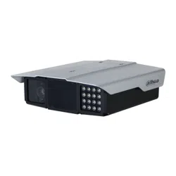
2.1 Appearance
Figure 2-1 Device appearance
2.2 Dimensions
Figure 2-2 Dimensions (mm [inch])

User's Manual
3
3 Quick Configuration
You can use the ConfigTool to quickly configure the Camera, including initialization, system update
and web client login.
●
The operation pages vary depending on different versions.
●
Get the ConfigTool installation package from technical support and install it on your local
computer.
3.1 Initializing the Camera
You can initialize the Camera, and cameras connected to the Camera in batches through the
ConfigTool.
Uninitialized devices are not available for any operations and are displayed in gray on the Camera
list.
Procedure
Step 1 Start the ConfigTool, and then click
Modify IP
.
The ConfigTool automatically searches for devices on the same network segment with the
computer.
Step 2 Select a device to be initialized, and then click
Initialize
.
Figure 3-1 Device initialization
Step 3 Set and confirm the password, and enter an email for future password reset.
The pages are for reference only, and might differ from the actual page.
Step 4 Click
Initialize
, and the system starts initializing the Camera.
is displayed for successful initialization, and is displayed for initialization failure.

User's Manual
4
Click the icon to view details.
Step 5 Click
Finish
.
3.2 Changing IP Address
Background Information
You can acquire and change the IP address of devices accessed through wired network. This section
uses changing IP address with the ConfigTool as the example.
Procedure
Step 1 Start the ConfigTool.
Step 2 Click
Modify IP
.
Step 3 Select the device(s) whose IP need(s) to be changed.
●
Change one IP address: Click
Edit
corresponding to the device.
●
Change IP addresses in batches: Select the devices, and then click
Batch Modify IP
.
Step 4 Set mode, IP, subnet mask and gateway.
Step 5 Click
Confirm
.
3.3 Upgrading the Camera
Background Information
Single upgrade and batch upgrade are supported.
Procedure
Step 1 Start the ConfigTool.
Step 2 Click
Device Upgrade
.
Step 3 Select the Camera to be updated.
●
Update one by one: Click corresponding to the Camera.
●
Update in batches: Select multiple devices, and then click
Batch Upgrade
.
Step 4 Select the update file.
Step 5 Update the Camera.
●
Update one by one: Click to start updating.
●
Update in batches: Click
OK
to start updating.
During update, if the Camera is disconnected, as long as the ConfigTool stays on the
update page, the upgrade will continue when the Camera is reconnected.
3.4 Logging in to Web
On the
Modify IP
page, click
Web
corresponding to the Camera, and then you are directed to the
login page of the web client. Enter the login username and password to log in.

User's Manual
5
4 Web Client Operations
You can access and manage connected devices, such as cameras and radars through the web client
of the Camera.
The web pages displayed in this section are for reference only, and might differ from the actual
model.
4.1 Web Introduction
Log in to the web client of the Camera through a browser, on which you can operate, configure and
maintain the Camera.
4.1.1 Recommended System Requirements
Table 4-1 Recommended system requirements
Component Recommended System Requirements
Operating system Windows 7 and later.
CPU Intel core i3 and later.
Graphics card Intel HD Graphics and later.
Memory 2 GB and bigger.
Monitor resolution 1024 × 768 and higher.
Browser Internet Explorer 11, Chrome 41/33, and Firefox 49.
4.1.2 Login
Background Information
●
For first-time login or login after the Camera is restored to factory defaults, initialization is
required.
●
Make sure that the IP address of the computer and that of the Camera are on the same network
segment. Otherwise, the initialization might fail.
Procedure
Step 1 Open the browser and enter the IP address of the Camera, and then press the Enter key.
Step 2 Enter and confirm the password.

User's Manual
6
Change the password from
Setting
>
System
>
Account
>
Account
>
Username
. For
details, see "4.7.9.2.1 Account".
Figure 4-1 Device initialization
Step 3 Select
Email Address
, and then enter an email address.
The email address is used for resetting password.
Step 4 Click
Confirm
.
Step 5 Enter
Username
and
Password
on the login window, and then click
Login
.
The account will be locked for five minutes after five failed username or password
attempts.
Step 6 On the
Live
page, click
Please click here to download and install the plug-in
to
download and install the plug-in.
The
Live
page is normally displayed.
4.1.3 Resetting Password
When you forget the password, you can set a new password.
●
You need to enter an email address during device initialization to receive the security code.
Otherwise, password reset is not available. You can also change the email address from
Setting
>
System
>
Account
>
Account
>
Username
. For details, see "4.7.9.2.1 Account".
●
The password of a device can only be reset up to 10 times a day.
●
You can only get two security codes for each QR code.
●
Use the security code to reset the password within 24 hours after you receive it. Otherwise the
security code will become invalid.
Procedure
Step 1 Open the browser and enter the IP address of the Camera, and then press Enter.
Step 2 Click
Forgot password?
on the login page, and then click
OK
in the pop-up window.

User's Manual
7
If Internet Explorer is used,
Stop running this script
is displayed. In this case, click
No
to
continue to run the script.
Step 3 Scan the QR code, and the scan result will be sent to the reserved email.
Step 4 Send the received scan result to support_gpwd@htmicrochip.com through the reserved
email address to get the security code.
Figure 4-2 Reset password (1)
Step 5 Enter the security code, and then click
Next
.
Step 6 Enter and confirm the new password.
Follow the password security prompt to set a password with a high security level.
Figure 4-3 Reset password (2)
Step 7 Click
OK
.

User's Manual
8
4.1.4 Web Functions
Figure 4-4 Tabs
Table 4-2 Tab functions
Function Content
Live View the real-time videos and captures of the camera.
Radar & Video
Integration
Integrates the video and radar detection results together, allowing you to view
the integrated images and metadata.
Radar Configure the radar and debug the detection result.
Playback
Plays back video recordings and videos related to traffic violations to track
events (if any).
Search Search for vehicles and recordings.
Setting
Configure intelligent traffic rules, the basic attributes of the Device, network
settings, event management, storage management, system management, and
view system information.
Alarm Set alarm prompts.
Logout Log out of the web client.
The common buttons on the web page are as follows.
Table 4-3 Common buttons
Button Description
Restores the parameter to the default value.
Restores the parameter to the value saved last time.
Saves current configurations.
4.2 Live
The
Live
page is displayed after you successfully log in to web. On this page, you can view the live
video image and the captured number plate, take snapshots, view event details, and more.

User's Manual
9
Figure 4-5 Live
Table 4-4 Description of live page
No. Description No. Description
1 Video stream 5 System functions
2 Live view 6 Functions of the live view
3 Logged plate number 7 Vehicle snapshot
4 Plate snapshot 8 Event list
4.2.1 Video Stream
●
Main Stream
: Make sure that the Camera can record videos and carry out network surveillance
when the network is normal. You can configure main stream resolution within the supported
range of the Camera.
●
Sub Stream
: Replaces main stream to make network surveillance and reduce the network
bandwidth usage when network bandwidth is insufficient.
●
Protocol
: Video surveillance protocol. Currently it only supports
TCP
.
●
Fluency
: Fluency of viewing the live video. The fluency can be set to
High
,
Middle
,
Low
and
Default
(recommended).
4.2.2 Live View
Displays the live video captured by the Camera. You can also click the icons to change the display
mode of live view.
●
: Adjust the image to original size or appropriate window.
●
: Click it to switch to big window. Click it again to exit big window.

User's Manual
10
Figure 4-6 Big window
●
: Click it to enable smart track detection. Number plate, vehicle bounding box, and other smart
tracking information will be displayed in the video image.
●
: Click it and the window is displayed in full screen; double-click or right-click to exit full
screen.
Table 4-5 Image adjustment
Icon Name Description
Brightness
Adjust the overall image brightness. Change the value when the
image is too bright or too dark. The range is from 0 to 128 (64 by
default).
Contrast
Change the value when the image brightness is suitable, but
contrast is not enough. The range is from 0 to 128 (64 by default).
Hue
Adjust the image hue. For example, change red into blue. The
default value is made by the light sensor and normally it does not
have to be adjusted. The range is from 0 to 128 (64 by default).
Saturation
Adjust the vividness of the colors, without influencing the overall
brightness of the image. The range is from 0 to 128 (64 by default).
—
Click it to restore brightness, contrast, saturation, and hue to their
default values.
In this image adjustment window, you can only adjust image brightness, contrast, hue, and
saturation of local web. To adjust system brightness, contrast, hue and saturation, go to
Setting
>
Camera
>
Image
>
General
.
4.2.3 Plate Number Recognition
Displays the plate number recognized by the Camera in real-time when a vehicle passes.
4.2.4 Plate Snapshot
Displays the snapshot of a license plate when a vehicle passes.

User's Manual
11
4.2.5 System Functions
Click the icons to set system functions, which include playback, video recording and snapshot query,
intelligent rules setting, alarm event setting, and system logout. See more details in the following
chapters.
4.2.6 Functions on the Live Interface
Set functions on the
Live
page, and then the system will display the desired information on the
Live
page.
Table 4-6 Function description of the Live page
Icon Name Description
Picture
Preview
Select the checkbox, and the Camera automatically
receives vehicle snapshots and detects event information
triggered by sources such as radar or video detection, and
displays such snapshots and information at the lower part
of the page.
The snapshots are saved in the storage path defined by
Setting
>
Storage
>
Storage
>
Storage Path
.
Type
Select the format of video recordings (
dav
by default).
Manual
Snapshot
Click it, and the Camera takes a snapshot when a vehicle
passes. The snapshot is saved in the storage path.
●
Enable
Picture Preview
first.
●
To change the storage path of snapshots, go to
Setting
>
Storage
>
Storage
>
Storage Path
.
Snapshot
Click it, and a snapshot is taken, even when there is no
vehicle passing. The snapshot is saved in the path defined
by
Setting
>
Storage
>
Storage
>
Storage Path
.
Digital Zoom
Click and drag to select any area in the video window, and
then the area will be zoomed into. In any area of the video
window, click or right-click to exit.
Video
Recording
Click it to start recording. Click again to stop
recording and the recorded video will be saved to the set
path.
The Camera will keep recording until the web page is
closed or you log out if the recording is not manually
stopped.
Easy Focus
Click it to start auto focus, local focus, and license plate
check for the monitoring image.
Picture Preview
and license plate check cannot be
enabled at the same time.

User's Manual
12
4.2.7 Vehicle Snapshot
Select
Picture Preview
, and then snapshots will be displayed when vehicles pass.
4.2.8 Event List
Select
Picture Preview
, and the event information will be displayed, including number, event types,
capture time, lanes, plates, vehicle color, speed, vehicle signs, and vehicle types.
4.3 Viewing Radar & Video Integration
Background Information
View the integrated data of the Camera video and radar detection results on one page.
Procedure
Step 1 Click
Radar & Video Integration
.
Step 2 On the left side, click icons at the lower-left corner to view vehicle details on the image.
●
Click to enable radar & video integration, and then the target ID, distance and
travelling speed are displayed on the image.
●
Click to display the radar targets.
●
Click to display the video targets.
●
Click to display the video image in full screen. Double-click or press Esc to exit the
full screen.
Step 3 Adjust the radar detection.
●
Click
On
or
Close
next to
Target Trajectory
to display or hide the target trajectory.
●
Different types of targets, such as Non-motor vehicles, pedestrians, large, middle and
small vehicles, can be displayed in different icons respectively.
Step 4 Click
Picture Preview
at the upper-right corner, and then the metadata obtained after the
radar & video integration are displayed on the list.
4.4 Radar Configuration
Configure the radar to accurately capture events during bad weathers and poor light conditions.
4.4.1 Radar Settings
4.4.1.1 Calibrating by Radar & Video
Calibrate the radar. Make sure when the radar sends signals to the camera, the camera can capture
the right target.
Procedure
Step 1 Select
Radar
>
Radar Settings
.
Step 2 Click
Calibrate by Radar & Video
.
Step 3 Select a channel on the prompted page, and then select the
Splicing Calibration

User's Manual
13
checkbox.
You can also calibrate the radar manually without enabling splicing calibration. In this case,
you need to manually measure the distance between the drawn calibration area and the
Camera.
Figure 4-7 Radar calibration
Step 4 Calibrate the radar.
●
Manual calibration
Set the coordinates of the calibration area and the trigger distance manually.
In situations where manual measurement is accurate, the precision of manual
calibration is higher than automatic calibration.
1) Select
Manual
next to
Calibration Mode
, and then adjust the calibration frame on the
image based on the on-site measurement.
You can also click , and then click
Calibration Area
to draw an area on the image.
2) Set the coordinates of the calibration area.
3) In the
Snapshot Setting
section, click
Snapshot Triggering Line
, and then draw the
lines on each lane.
The distance between the triggering line and the Camera is displayed on the bottom.4)
Adjust the triggering distance as needed, and then click
Confirm
.
5) Click
Calibrate
, and then click
Confirm
.
●
Automatic calibration
Set the width of the calibration area to be the same as that of the actual road, and then
the algorithm will automatically calibrate the radar.
1) Select
Auto
next to
Calibration Mode
.
2) Set the
Area Width
according to the actual width of the road.
3) Click
Calibrate
, and then click
Confirm
.
Step 5 Click
Back
.

User's Manual
14
4.4.1.2 Configuring General Information
Set the parameters of the radar and the lanes.
Procedure
Step 1 Select
Radar
>
Radar Settings
.
The information of the connected radar is displayed on the top of the page, and you can
adjust the
Sensitivity
.
Under general situations, we recommend you leave the sensitivity as default to avoid false
detections brought by higher sensitivity.
Step 2 In the
Road Info
section, set the lane width and direction based on the actual site.
Figure 4-8 Lane information
Step 3 In the
Installation Info
section, set the installation information of the Camera.
Table 4-7 Installation information description
Parameter Description
Radar Height The installation height of the Camera.
Angle Correction
Adjust the installation angle of the radar. Make sure the angle is the
same as that in the
Visualized Data
section. For details, see "4.4.2
Configuring Visualized Data".
Horizontal Offset
Adjust the horizontal offset of the radar. Make sure the value is the
same as that in the
Visualized Data
section.
Step 4 In the
Speed Correction
section, set the speed range and the speed correction value of
the Camera.
Step 5 Click
OK
.
4.4.2 Configuring Visualized Data
See the effect of your configurations on radar detection in real time. You can also adjust some of the
radar parameters and view the changes.

User's Manual
15
Procedure
Step 1 Select
Radar
>
Visualized Data
.
Step 2 Adjust the value of angle correction and horizontal offset.
Click the image at the lower-right corner to see the correction standards.
Step 3 Click to display
Target Trajectory
.
You can see the trajectory of targets the radar detects.
Figure 4-9 Visualized Data
Step 4 Click , you can see the detection points of the radar on targets.
When the target is large and the detection sensitivity is set high, the radar might recognize
it as two targets.
4.5 Viewing Recordings
You can search for, view and download recordings.
Procedure
Step 1 Click
Playback
.
Step 2 Set
File Type
and data source (
Data Src
), and set record time.
The data source is
Hard disk
(here referred to as TF card) by default. No video will be
played if there are no videos stored on the TF card.

User's Manual
16
Figure 4-10 Playback file
Step 3 Select a day with a blue point which indicates that there are recordings on that day, and a
colored progress bar is displayed on the timeline.
●
Point to this day, and the color turns to orange.
●
Select this day, and the color turns to green.
Step 4 Select a record type, and then only files of the selected types will be displayed on timeline
and on the file list.
Figure 4-11 Record type
You can click each time format to play back the videos in 24-hour mode, 2-hour mode, 1-
hour mode, and 30-minute mode respectively.
Figure 4-12 Time format
Step 5 Click any time on the progress bar, and the system plays back recordings starting from that
time.
Figure 4-13 Timeline
Table 4-8 Video playing description
Icon Function Description
Play and pause
●
: The video is paused or not being played.
●
: The video starts playing.
Stop Stop playing video.
Play by frame Play by frame.
Slow Slow down.
Fast Speed up.
Step 6 Click , and videos recorded on a selected day will be displayed in a list.

User's Manual
17
Figure 4-14 Playback file
Table 4-9 Playback file description
Parameter Description
Search for all the video files within the selected period.
Click it to download files to local.
Click it to go back to the calendar page, where you can search for
and play back videos of other periods.
Step 7 Double-click a file in the list, and the file will be played with information displayed such as
the file size, start time, and end time.
4.6 Search
You can search for snapshots, vehicle flow, and video recordings on the
Search
page.
4.6.1 Picture Query
4.6.1.1 Querying Memory Card Images
On the
Memory Card Image
page, you can search for and download the images stored in the TF
card of the Camera.

User's Manual
18
Make sure the TF card is inserted into the Camera; otherwise, there might be no results.
Procedure
Step 1 Select
Search
>
Picture Query
>
Memory Card Image
.
Figure 4-15 Memory Card Image
Step 2 Configure the parameters, and then click
Search
.
Table 4-10 SD picture parameters
Parameter Description
Begin Time
Set the begin time and the end time to define a period, and then you can
search for images stored on the TF card within this period.
End Time
Event Type
All Picture
: Search for all snapshots.
Mix Events
: Search for snapshots related to events, which include but
are not limited to
ANPR
,
Cross Solid White Line
, and
Wrong-way
Driving
.
Vehicle Sign
Search for snapshots by the selected vehicle sign.
You can select
All
,
Unknown
or a specific vehicle sign.
Lane Select the capture lane.
Speed Range
Select the
Speed Range
checkbox, and set the speed range to search for
images of vehicles within the defined speed range.
Record Interval
The length of a recorded video associated with the snapshot that you
want to save.
Plate
Select the
Plate
checkbox, and then enter the plate number to search for
images related to this plate.
This icon is displayed next to the traffic violation snapshot when
Related
Record
is enabled in
Advanced Parameter
(except
ANPR
) under
Setting
>
Event
>
ANPR Snapshot
>
Rule Config
.
Step 3 Select the images that you need, and click
Open
to view the images in photo viewer.
Step 4 Select the images that you want to download, and then click
Download
.
Step 5 Select the path to save the images, and the system starts downloading the images to your
computer.

User's Manual
19
4.6.1.2 Setting Downloading Attribute
You can configure the image information.
Procedure
Step 1 Select
Search
>
Picture Query
>
Download
.
Step 2 Set
Download Image by
to download snapshots based on their
Creation Time
or
Snapchat Time
.
Step 3 Select
Download Mode
.
●
Selected File
: Download the selected snapshots.
●
Selected Time
: Download all images captured during the set time period. You can set
the time in the
Memory Card Image
tab.
Step 4 Select cutouts that you want to download from
All
,
Plate Cutout
,
B/W Plate Cutout
,
Front Seat Passenger’s Face
(cutout of front-seat passenger’s face),
Driver Face
, and
Vehicle Body Cutout
.
Step 5 Name the snapshots. Click
Help
to view the image naming rule. Click
Reset
to go back to
default.
Step 6 Click
Save
.
Figure 4-16 Downloading attribute
4.6.1.3 Local Image
You can view images saved on your computer and verify whether the image was tampered with a
watermark.

User's Manual
20
To view or set the save path of images on your computer, go to
Setting
>
Storage
>
Storage
>
Storage Path
.
Procedure
Step 1 Select
Search
>
Picture Query
>
Local Image
.
Step 2 Click
Browse
to select a picture.
Step 3 Click
Watermark
, and view result under
Watermark Verification
.
●
When the result is
Error
, the picture is tampered.
●
When the result is
Normal
, the picture is not tampered.
Click
Open
or double-click the picture if you need to preview the picture.
4.6.2 Flow Query
Background Information
You can search for traffic flow and pedestrian flow within the defined period.
The function is available on select models, and might differ from the actual product.
Procedure
Step 1 Select
Search
>
Flow Query
>
Flow Query
.
Step 2 Set
Start Time
and
End Time
of your search.
Step 3 Click
Search
.
Step 4 Select search results, and click
Backup
to save the results to computer.
Step 5 Click
Clear
to delete all the current results.
Figure 4-17 Flow query
4.6.3 Video Search
Search for the video recordings stored on your computer to track abnormal events (if any).

User's Manual
21
4.6.3.1 Recording
You can search for a recorded video on your computer and play back the video.
●
Click on the
Live
page, and the Camera starts recording. The recorded video is saved to the
path defined in
Setting
>
Storage
>
Storage
>
Storage Path
.
●
The function is available on select models, and might differ from the actual product.
Procedure
Step 1 Select
Search
>
Search Video
>
Record
.
Step 2 Click
Select File
to select the recorded video on your computer, and then you can play
back the video.
Figure 4-18 Record
Table 4-11 Play parameters
Icon Description
Click it to select
Original
or
Adaptive
playback.
Click it to enable smart track detection. Number plate, vehicle bounding
box, and other smart tracking information will be displayed on the video
image.
Click it to enter full screen. Double-click the video image or press Esc to exit.
Click to enable radar & video integration, and then the target ID, distance
and travelling speed are displayed on the image
Click to display the radar targets.
Click it to play back the video. Click to pause.
Click it to stop playing back the current video.
Click it to slow down the video to play at × (1/2), × (1/4) or × (1/8). Click
to restore to normal playing speed.

User's Manual
22
Icon Description
Click it to speed up the video to play at × 2, × 4, or × 8. Click to restore
to normal playing speed.
Click it to play back the next frame.
4.6.3.2 Watermark
Verify the watermark of selected video recordings to check whether the recording was tampered.
Only .dav recording is supported.
Prerequisites
Before verifying the watermark, you need to select
Watermark
and configure
Watermark String
from
Setting
>
Camera
>
Video
>
Video Stream
>
Main Stream
.
The watermark character is
DigitalCCTV
by default.
Procedure
Step 1 Select
Search
>
Search Video
>
Watermark
.
Step 2 Click
Select File
to select a recording.
Step 3 Click
Watermark
. The system will display the verification progress and normal watermark
information.
●
If the video is verified to be authentic, the watermark you set is displayed next to
Watermark Info
.
●
If the video is tampered, you can check the details next to
Tampered Watermark
.
Figure 4-19 Watermark
4.7 Setting
Set parameters of the Camera, including intelligent traffic rules, network settings, remote devices,
event management, storage management, system management, and system information, to realize
functions such as image composition, speed measuring, network connection, data storage and
alarm.

User's Manual
23
4.7.1 Camera Settings
After connecting the Camera to the network and viewing the live video on its web client, you can
adjust the image and video parameters of the Camera to get clear images.
4.7.1.1 Camera Attributes
4.7.1.1.1 Configuring General Parameters
You can configure the brightness, contrast, saturation, mode, and other properties of the camera
channels.
Procedure
Step 1 Select
Setting
>
Camera
>
Image
>
General
.
Step 2 Select a channel and then configure the corresponding parameters.
Figure 4-20 General
Table 4-12 General parameters
Parameter Description
Brightness
●
Both the darker areas and the brighter areas will be changed together
when adjusting the brightness. The image might become blurry when
the value gets bigger. The recommended range is 40–60, and the
available range is 0–100.
●
It is 50 by default. The larger the value, the brighter the image.
Contrast
●
The larger the value, the darker the dark area, and the more exposed
the bright area.
●
The image might become blurry when the value gets smaller. The
recommended range is 40–60, and the available range is 0–100.
●
It is 50 by default. The larger the value, the stronger the contrast.
Saturation
●
Saturation value does not change the overall image brightness.
●
The larger the value, the more saturated the image.
●
It is 50 by default. The smaller the value, the more unsaturated the
image. The recommended range is 40–60, and the available range is
0–100.

User's Manual
24
Parameter Description
Mode
●
Colorful
: The image is always colored.
●
Auto Switch by Brightness
: When the brightness is higher than the
threshold, the image automatically changes to color; when it is below
the threshold, the image changes to black and white.
●
B/W
: The image is always black and white.
ICR Switch
●
Auto
: You need to pre-set the brightness in this mode. When the
ambient brightness is higher than the pre-set value, the CPL will start
to work.
●
CPL
: The CPL is always running. Applicable to scenarios with high
brightness.
●
IR
(for IR models) or
Normal
(for white light models): Applicable to
scenarios with low brightness.
Ambient Brightness Set the brightness value of the environment where the device is located.
Sync Signal
Select the synchronization signal mode.
When you select
External Sync
, you can set a fixed synchronization phase
value by dragging the slider for day and night respectively to adjust the
brightness of the red light in different scenes.
1. Select
Auto Phase
.
2. Click
Setting
to set the phase of each shutter interval. Automatic
phase interval can only be within the day/night phase range.
3. Select the indicator need to be adjusted, the system displays a yellow
box.
4. Click
Test
, the system provides reference values, you can fine-tune on
the basis of the reference value.
5. Click
OK
.
In the setting interface, the red box indicates the current valid phase
value.
Day Phase Manually adjust the phase value of the sync signal during the day.
Night Phase Manually adjust the phase value of the sync signal during the night.
Step 3 Click
Save
.
4.7.1.1.2 Configuring Shutter
You can configure shutter mode, exposure mode, and gain mode.
Procedure
Step 1 Select
Setting
>
Camera
>
Image
>
Shutter
.
Step 2 Select a channel, and then configure the corresponding parameters.

User's Manual
25
Figure 4-21 Shutter
Table 4-13 Shutter parameters
Module Parameter Description
Shutter
Mode
Single Shutter Video and snapshot share the same exposure mode.
Double Shutter
●
Half FPS
: Video and snapshot take half of the frame
respectively.
●
Full FPS
: Snapshot takes 1frame, and video takes the
rest of the frames.
Video Shutter
and
Snap Shutter
can be separately
configured.
Three Shutter
Video Shutter
,
Snap Shutter
and
Recognition Shutter
can
be separately configured.
Three Shutter
mode is available only when
Common
Mode
is set to
Snap Match Mode
from
Setting
>
Event
>
ANPR Snap
>
Illegal Capture
>
Other Settings
.
3D NR
Video/Snap
Tridim Denoise
When it is
On
, 3D NR is enabled to reduce noise of
video/snapshot.
Video/Snap
Spatial
Spatial video/snapshot denoising. The higher the value, the
less noise there is.
Video/Snap
Temporal
Temporal video/snapshot denoising. The higher the value,
the fewer the flicker noise.
Picture
Scene
You can change the scene and adjust the sharpness of the
corresponding scene. Scenes available:
Dawn/Dusk
,
Daytime
, and
Night
.
Sharpness
You can set the sharpness of the corresponding scene.
The higher the value, the clearer the image. But there will be
noise if the sharpness is too high.
WDR
Select
On
to enable WDR (wide dynamic range), which helps
provide clear video images in bright and dark light.

User's Manual
26
Module Parameter Description
Exposure
Mode
●
In
Auto
mode, only
Manual
iris type is available.
●
In
Force
mode, several iris types are available, and you
also need to configure the
Iris Adjust Mode
. If
Manual
is selected, you can manually drag the slider to adjust
the value.
Iris Type Displays the detected iris type.
Mode
Select the way of adjusting exposure mode. You can select
from
Manual
and
Auto
.
Shutter
You can select the shutter value, or select
Customized
Range
, and then set the shutter range.
Only available when
Mode
is set to
Manual
.
Shutter Scope
Set the time range of shutter.
Only available when
Shutter
is set to
Customized Range
.
Gain Scope
Set the value range of gain.
Only available when
Mode
is set to
Manual
.
WB Mode Set scene mode to adjust the image to its best status.
Step 3 Click
Save
.
4.7.1.1.3 Configuring Metering Zone
This section provides guidance on setting the measure mode of metering zone.
Procedure
Step 1 Select
Setting
>
Camera
>
Image
>
Metering
.
Figure 4-22 Metering
Step 2 Configure the parameters.

User's Manual
27
Table 4-14 Metering parameter description
Parameter Description
Plate Light
When selecting
On
, you can turn
ON
backlight and frontlight according to
scene requirements to improve the backlight and frontlight image
brightness.
Backlight
Frontlight
Measure Mode
●
Global Measure
: Measure the brightness of the whole image area and
intelligently adjust the overall image brightness.
●
Partial Measure
: Measure the brightness of drawn areas and adjust the
overall image brightness to the opposite.
Draw areas on the image, and you can right-click an area or select it and
then click
Delete
to delete it. Click
Clear
can delete all areas.
Step 3 Click
Save
.
4.7.1.1.4 Configuring Focus
Background Information
Adjust the focus of the Camera.
Procedure
Step 1 Select
Setting
>
Camera
>
Image
>
Focus
.
Figure 4-23 Focus
Step 2 Configure the parameters.
Table 4-15 Description of focus parameters
Parameter Description
Lens Type
The type of the Camera lens. Select
Manual Vari-Focal
to restart the
Camera when the lens is not standard.
Zoom Drag the slider to zoom in or out the video image at the selected speed.
Focus Drag the slider to adjust the camera focus at the selected speed.
Speed Set the speed of adjusting the value of zoom in/out and focus.

User's Manual
28
Parameter Description
Auto Focus Automatically adjusts the camera focus to get clear images.
4.7.1.2 Video Attributes
4.7.1.2.1 Configuring Video Parameter
Configure the parameters of video stream.
Procedure
Step 1 Select
Setting
>
Camera
>
Video
>
Video Stream
.
Figure 4-24 Video stream
Step 2 Configure the parameters.
Table 4-16 Video stream parameter
Parameter Description
Encode Mode Modes of H.264M, H.264H, MJPEG, and H.265 can be selected.
Resolution
The higher the value, the clearer the overall image. For each resolution,
the recommended bit stream value is different.
The resolution of sub stream cannot be greater than that of main
stream.
Frame Rate (FPS)
The higher the value, the smoother the video image. The frame rate
might vary due to different resolutions.
Bit Rate Type
You can select from
VBR
(variable bitrate) and
CBR
(constant bitrate).
●
VBR
: Gives the best balance between quality and file size as the
bitrate can be altered depending on the video.
●
CBR
keeps the bitrate the same during encoding, and it is more
advantageous to use when the network connection is limited to
performing at, for example, 320 Kbps.

User's Manual
29
Parameter Description
Quality
6 quality levels are available. The higher the value, the better the quality.
You need to configure the image quality when
VBR
is set to
Bit Rate
Type
.
Bit Rate
Higher bit rate signifies greater image or video quality, but also occupies
more storage space.
You need to configure the bit rate when
CBR
is set to
Bit Rate Type
.
Max. Bit Rate It is the upper limit of stream in VBR. In CBR, the value is fixed.
I Frame Interval
The number of P-frame between two I-frames. The number varies
according to the bit rate. The range is 25–150. We recommend
configuring the value to be twice the amount of the bit rate.
Watermark Settings
You can verify the watermark to check whether the video has been
tampered.
Select the
Watermark Settings
checkbox to enable watermark
verification. The watermark character is
DigitalCCTV
by default.
Watermark character consists of up to 85 characters with numbers,
letters and underlines.
med.StreamSmoothi
ng
Set the video smoothness.
Enable
Enable sub stream when your network bandwidth is insufficient or other
conditions that influence the video smoothness in main stream.
Step 3 Click
Save
.
4.7.1.2.2 Configuring Video OSD
Configure the OSD information of videos.
Procedure
Step 1 Select
Setting
>
Camera
>
Video
>
Video OSD
.
Figure 4-25 Video OSD

User's Manual
30
Step 2 Configure parameters.
Table 4-17 Description of video OSD parameters
Parameter Description
Font Size Set the font size of
Main Stream
or
Sub Stream
.
Channel Title
Enable the function and set the channel title, coordinates and font color
(can be customized) of channel information OSD.
Time Title
Enable the function and set the coordinates and font color (can be
customized) of time information OSD. You can select
Display Week Info
to display week information on the video image.
GPS Title
Enable the function and set the coordinates and font color (can be
customized) of channel information OSD.
Traffic Flow Info
Enable the function and set the coordinates and font color (can be
customized) of flow information OSD.
Queue Info
Enable the function and set the font color (can be customized) of queue
information OSD.
Custom
Enable the function and set the coordinates, custom title and font color
(can be customized) of custom information OSD.
You can add up to 5 custom titles.
Step 3 Click
Save
.
4.7.1.2.3 ROI
Set one or more interested areas in the image, and then the selected image will be displayed with
the configured quality.
Procedure
Step 1 Select
Setting
>
Camera
>
Video
>
ROI
.

User's Manual
31
Figure 4-26 ROI
Step 2 Drag anywhere in the video image to draw the region of interest. You can draw more than
one region when necessary.
You can click
Clear
to delete all the regions of interest, or click
Delete
or right-click on the
video image to delete the most recently drawn area.
Step 3 Set the image quality of the regions of interest. 6 quality levels are available. The higher the
value, the better the quality.
Step 4 Click
Save
.
4.7.2 Network Settings
You can set the network parameters of the Camera.
4.7.2.1 TCP/IP
You can set the IP address, DNS server and other parameters of the Camera to make sure that the
Camera can connect to other devices on the network.
Procedure
Step 1 Select
Setting
>
Network Settings
>
TCP/IP
.

User's Manual
32
Figure 4-27 TCP/IP
Step 2 Configure parameters.
Table 4-18 TCP/IP parameters
Parameter Description
Host Name
Set the name of the current host, with a maximum length of 15
characters.
Ethernet Card
Dual Ethernet cards are supported. Select an Ethernet card and then click
Set as Default
to set it to the default.
Mode
Select a network mode.
●
DHCP mode: Automatically obtains the IP address. The
IP Address
,
Subnet Mask
, and
Default Gateway
cannot be set when DHCP is
enabled. You can check the current IP address regardless if the DHCP
takes effect.
●
Static mode: Manually set
IP Address
,
Subnet Mask
, and
Default
Gateway
, and then click
Confirm
. The web page will automatically
go to the login page of the set IP address.
MAC Address MAC address of the host, which cannot be modified.
IP Version Only IPv4 is supported.
Address Enter IP address.
Subnet Mask
Set a subnet mask as needed. The subnet prefix is a number in the range
from 1 through 255. The subnet prefix identifies a specific network link
and usually contains a hierarchical structure.
Default Gateway
Set a default gateway on the same network segment as the IP address as
needed.
Preferred DNS IP address of DNS.
Alternate DNS IP address of the alternate DNS.
Step 3 Click
Save
.

User's Manual
33
4.7.2.2 Port Settings
4.7.2.2.1 Port
You can set the information of the connected ports to access the Camera through different protocols
and configuration tools.
Procedure
Step 1 Select
Setting
>
Network
>
Port
>
Port
.
Step 2 Set the maximum number of clients accessing the Camera at the same time (such as web
client and platform client) and each port value of the Camera.
Figure 4-28 Port
Step 3 Click
Save
.
4.7.2.2.2 ONVIF
Enable ONVIF, and then network video products produced by different manufacturers can
communicate with each other.
Login verification is required by default when ONVIF is enabled.
Procedure
Step 1 Select
Setting
>
Network Settings
>
Port
>
ONVIF
.
Step 2 Select
Open
or
Off
as needed.
●
By turning on ONVIF authentication, login username and password are required when
logging in through ONVIF.
●
Login verification is not required when turning off ONVIF authentication.
Step 3 Click
Save
.
4.7.2.3 Registration
Background Information
Configure automatic registration, and the current device location will be reported to the server
specified by the user when the Camera is connected to internet, so that the client software can use
the server to access the Camera, and the server can perform operations such as live view,

User's Manual
34
monitoring, and configuration of the parameters of the Device.
Procedure
Step 1 Select
Setting
>
Network Settings
>
Register
.
Step 2 Select
Enable
to enable automatic registration, and then enter the address, port, and sub-
device ID.
Table 4-19 Auto register parameters
Parameter Description
Address Server IP address or server domain that you want to register to.
Port Port of the server for auto register.
Sub-Device ID
ID of the automatically registered device assigned by the server.
Ensure that the ID of the automatically connected device is unique during
configuration.
Step 3 Click
Save
.
4.7.2.4 Multicast
When multiple users preview the video of the same device, unavailability might happen due to
network bandwidth restriction. You can fix it by setting up a multicast IP (224.0.0.0–239.255.255.255)
to access videos through the multicast protocol.
Procedure
Step 1 Select
Setting
>
Network Settings
>
Multicast
.
Step 2 Select the checkbox of
Enable
to enable the function.
Step 3 Enable main stream or sub stream based on the actual situation and set IP address and
port number.
Step 4 Click
Save
.
4.7.2.5 P2P
If enabled, the camera can be added to other platforms through P2P.
Procedure
Step 1 Select
Setting
>
Network Settings
>
Platform Access
>
P2P
.
Step 2 Select the checkbox of
Enable
.
Step 3 Click
Save
.
You can add the camera to other platforms using its serial number or by scanning its QR
code.
4.7.2.6 Routing Settings
The Camera supports configuring routings for dual NICs, and accessing gateways of target network
segments.
Procedure
Step 1 Select
Setting
>
Network Settings
>
Routing Settings
.
Step 2 Select Ethernet card and enter IP segment, subnet mask and default gateway.
Step 3 Click
Add
, and then
Save Succeeded
appears at the bottom and the routing is added to

User's Manual
35
the list.
●
Click to delete routing one by one.
●
Click
Clear
to quickly delete all added routings.
Figure 4-29 Routing settings
4.7.2.7 802.1x
802.1x is a port-based access control and authentication protocol, which can restrict unauthorized
devices or users from accessing the LAN through the access port. When the switch in the network is
configured with 802.1x, the Camera also needs to be set to 802.1x, otherwise users cannot access the
Camera through the network.
Procedure
Step 1 Select
Setting
>
Network Settings
>
802.1x
.
Step 2 Select
Enable
, and then select an Ethernet card. The 802.1x protocol of the NIC is enabled.
Figure 4-30 802.1x
Step 3 Leave the
Authentication Mode
as default, and then enter the username and password
for authentication. The username must be the one authorized on the server side.
Step 4 Select
CA Certificate
, click
Browse
to select the CA certificate from local computer.
Contact technical support to obtain the CA certificate.
Step 5 Click
Save
.

User's Manual
36
4.7.3 Remote Device
Background Information
Remote device (such as enforcement camera or IP camera) information will be displayed on the
Add
Camera
page if any of such devices is in use. You can enable the remote device to work with the
Camera to capture events. Currently, only events of crossing the stop line and running a red light can
be captured by combining the Camera and remote device.
This function is available only in
E-Police
mode.
Procedure
Step 1 Select
Setting
>
Add Camera
>
Remote Config
.
Step 2 Set the delay time for sub camera in
Snapshot Delay Time for Sub Camera
.
Step 3 Select a remote device, and then click .
Step 4 Select
On
to enable using the remote device, and modify other device information such as
name, IP address, login username, and password.
Step 5 Select
Linkage Snapshot
to enable snapshot by the Camera.
If a storage device is used, the snapshots captured by the Camera and the remote device
will be composited, and saved to the storage device. If no, the snapshots will be saved to
the storage path defined on the web page of each device.
Step 6 Click
Save
.
Figure 4-31 Add camera
4.7.4 Event
You can configure how the Camera responds when alarms or abnormal events occur.

User's Manual
37
4.7.4.1 Intelligent Scheme
4.7.4.1.1 Switching between E-police and ANPR
Background Information
You can switch the working mode of the Camera between E-police and ANPR.
●
ANPR
is applicable to road sections without signal lights to detect violations such as speeding,
driving slow, not wearing seat belt, calling while driving, and more. See "4.7.4.3 Configuring
ANPR Snapshot".
●
E-Police
is ideal for intersections with signal lights to detect violations such as running a red
light, and more. See "4.7.4.2 Configuring Electronic Police".
Figure 4-32 Select a working mode
Procedure
Step 1 Select
Setting
>
Event
>
Smart Plan
>
Smart Plan
.
Step 2 Select
E-police
or
ANPR
.
Step 3 For ANPR, set
Scene Type
.
●
General
: For capturing vehicles.
●
People
: For capturing people and non-motor vehicles.
●
Non Flashing Light
: For the scenes not using illuminator.
Step 4 Click
Save
.
4.7.4.1.2 Configuring Blocklist and Allowlist
An alarm is triggered when a vehicle is detected in the blocklist. A vehicle in the allowlist will not be
captured.
Allowlist Settings
Background Information
You can enable fuzzy matching for allowlist. In this way, if the fuzzy matching result shows that the
number plate of a vehicle is in the allowlist, the vehicle will not be captured and there will be no
alarm.
Procedure
Step 1 Select
Setting
>
Event
>
Smart Plan
>
Vehicle Blocklist/Allowlist
>
Allowlist Settings
.
Step 2 Select
Enable
to enable the allowlist.
Step 3 Select
Fuzzy Matching
to enable fuzzy matching.

User's Manual
38
Step 4 Configure the matching rule.
●
Main Matching Characters
: The specific digit(s) that should be exactly matched.
●
Min Matching Characters
: The minimum number of digits that should be exactly
matched.
For example, if you select 1, 2 and 4 for
Main Matching Characters
and enter 2 for
Min
Matching Characters
, the system will successfully recognize a vehicle when any two
among digit 1, 2, and 4 are exactly matched.
Figure 4-33 Allowlist settings
Step 5 Click
Save
.
Allowlist
You can search to see whether a plate number is included in the allowlist, or you can import or
export plate numbers in the allowlist.
Procedure
Step 1 Select
Setting
>
Event
>
Smart Plan
>
Vehicle Blocklist/Allowlist
>
Allowlist
.
Step 2 Add a number plate.
1) Click
Add
.

User's Manual
39
Figure 4-34 Add
2) Enter the entire plate number.
3) Set the start time and end time to add the plate number in the allowlist. The plate
number will be outside of the allowlist beyond this time period.
4) Select the plate color, vehicle type, plate type and vehicle color. Enter the owner of
vehicle.
5) Click
Save
.
6) To save and add more, select
Add More
before clicking
Save
.
Related Operations
●
Search for a plate number: Enter the plate number (or part of it) that you want to search for, and
then click
Search
to check whether it is in the allowlist.
●
Modify plate information: Click
Modify
to modify detailed information of the corresponding
plate number. Click
Confirm
to save the settings.
●
Delete a plate number: Click
Delete
to delete the corresponding plate number.
●
Delete plate number in batches: Click
Clear All
, and then click
Confirm
in the pop-up box to
delete all the information in the allowlist.
●
Import allowlist plates in batches: Click
Browse
, and then select the path to import the file to.
Click
Import
to import the allowlist information to the system.
●
Export allowlist plates in batches: Click
Export
, and then select the path to save the file to. Click
Export
to export the allowlist information to the system.
●
You can encrypt the file when importing and exporting the allowlist, depending on your actual
needs.

User's Manual
40
Blocklist
An alarm will be triggered when a vehicle in the blocklist is detected.
Select
Setting
>
Event
>
Smart Plan
>
Vehicle Blocklist/Allowlist
>
Blocklist
, and then select
On
to enable the blocklist function.
The search, import, and export of blocklist are similar to that of allowlist. See " Allowlist".
Figure 4-35 Blocklist search
4.7.4.2 Configuring Electronic Police
Configure electronic police parameters.
Make sure that you have set
Smart Plan
to
E-police
. For details, see "4.7.4.1.1 Switching between E-
police and ANPR".
4.7.4.2.1 Configuring Violation Capture
Configure the video detection parameters for detecting traffic violations.
Follow this order to configure violation capture: Rule config > lane property > lane config > vehicle
detection (Car Detect) > other settings. This is described separately in the configuration order below.

User's Manual
41
Figure 4-36 Configuration order for violation capture
Rule Configuration
You can select the traffic violation types and configure the corresponding parameters of the images
of the captured vehicle.
Procedure
Step 1 Select
Setting
>
Event
>
E Police
>
Violation Snapshot
.
Step 2 In the
Rule Config
section, click , and then configure picture parameters.
Figure 4-37 Rule configuration (1)

User's Manual
42
The parameter table describes the parameters involved in all event types, and might differ
from the actual page.
Figure 4-38 Configure picture parameters (1)
Table 4-20 Picture parameters (1)
Category Name Description
Picture
Parameter
Original Image
The original picture of the vehicle that is violating traffic
rules.
Composite
Picture
The compound picture of several sequential images of the
vehicle violating the traffic rules.
Close-up Image The close-up of the offending vehicle.
Save Locally
Save the vehicle picture locally when an offending vehicle
is captured.
Report Picture
Upload the vehicle picture to the upper-level device or
platform when a vehicle is captured.
Resolution Select picture resolution.
Quality Select the level of picture quality.
Size Limit the size of the picture.
Copy to
Copy the current picture configuration to the same-type
rules or all the rules. After selecting an option from
Copy
to
, click
Copy
.
Snapshot and
Picture
Synthesis
Setting
Feature Region
Centering on the vehicle, enter the height and width of
the close-up of the vehicle.
Compound order
of one pictures
●
S
: Close-up
●
1
: Original images
Step 3 Click
OK
.

User's Manual
43
Step 4 Click , and then configure advanced parameters.
The parameter table describes the parameters involved in all event types, and might differ
from the actual page.
Figure 4-39 Advanced parameters (1)
Table 4-21 Advanced parameters (1)
Category Name Description
Trigger Source
Loop Unavailable
Video
The system analyzes the live video to detect
traffic violations. Once a violation is detected, the
system automatically captures images of the
offending vehicle.
Copy to
Copy the current picture configuration to the
same-type rules or all the rules. After selecting an
option from
Copy to
, click
Copy
.
Rule Parameter
Driving Direction to
Trigger Snapshot
Vehicle driving direction to the camera.
Schedule
The period during which the alarm is valid. To set
a time, you can click Setting, and then drag your
cursor over the time table or select days, and
enter hours in the entry fields.
Vehicles that trigger
snapshots
The vehicle types to capture.
Flashing Light
Day
Select which flashing light flashes when

User's Manual
44
Category Name Description
Config
Night
snapshots are taken during daytime or night.
A snapshot can be associated with up to 5
flashing lights.
For example, select
F1
from the
1st or 4th Image
section, meaning flashing light F1 flashes when
taking the 1st and 4th snapshots.
Step 5 Click
Save
.
Lane Property
Procedure
Step 1 Select
Setting
>
Event
>
E Police
>
Violation Snapshot
.
Step 2 In the
Lane Property
section, configure lane properties.
Figure 4-40 Lane property (1)
Table 4-22 Lane property parameters (1)
Parameter Description
Road Direction The direction of the lane.
Passing Direction The geographical direction of the lane.
Upload Image of
●
All Violations
: Captures and reports all violations of vehicles on
the lane.
●
Violation with Highest Priority
: When the vehicle triggers
multiple violations, the Camera reports only the event with the
highest priority.
Road Code
The code of the roadway and route.
Route Section Code
Step 3 Click
Save
.
Lane Parameters
Background Information
Configure lane information and events that you want the Camera to detect.
Procedure
Step 1 Select
Setting
>
Event
>
E Police
>
Violation Snapshot
.
Step 2 In the
Lane Config
section, configure lane parameters.

User's Manual
45
Figure 4-41 Lane configuration
Table 4-23 Lane parameters
Parameter Description
Lane Direction
The arrow direction of the lane line needs to be the same as that of the
travelling vehicle.
●
Vehicle Tail
: Lane line arrow points upward.
●
Vehicle Head (Video)
: Lane line arrow points downward.
Edit Line
Select the checkbox to enable the function, and then you can adjust the
lane lines by dragging the corners on the image.
Step 3 Click a line type, and then draw the lane lines on the image.
To clear the lane lines or regions that you have drawn, click .
Table 4-24 Lane lines
Parameter Description
Lane Line
Each lane needs to have two lane lines, shown as blue lines with
arrows. The arrow indicates the direction in which the vehicles travel.
The drawn lines should go along the actual lane line.
Stop Line The actual stop line on the road.
Front Line
The line which triggers the first capture of the vehicle running the red
light and traveling on the wrong lane.
Middle Line
The line which triggers the second capture of the vehicle running the
red light and traveling on the wrong lane.
Back Line
Used to judge whether a vehicle is going straight. It triggers the third
capture of the vehicle running the red light (straight going) and
traveling on the wrong lane.
Left Turn Division
Used to judge whether a vehicle is turning left. It triggers the third
capture of the vehicle running the red light and traveling on the
wrong lane.
Right Turn Division
Used to judge whether a vehicle is turning right. It triggers the third
capture of the vehicle running the red light and traveling on the
wrong lane.

User's Manual
46
Parameter Description
Waiting Area
Boundaries
The end line of the waiting area. Going beyond it will be regarded as
running the red light.
Illegal U-Turn Used to judge whether a vehicle is making a U-turn when not allowed.
Auto Drawing
Install the plug-in before using the
Auto Drawing
function.
Click
Auto Drawing
, and then the system automatically draws lane
lines. You can adjust the auto lines as needed.
Step 4 Click to select and show a lane on the video image, and then the configurations of this
lane will be enabled.
Step 5 Click
Save
.
Vehicle Detection
Procedure
Step 1 Select
Setting
>
Event
>
E Police
>
Violation Snapshot
.
Step 2 In the
Vehicle Detection
section, click the line or region type, and then draw on the video
image.
●
To draw a line, click the line type and then drag your mouse cursor on the image.
●
To draw a region, click the region type, and then draw the lines by dragging your cursor
on the image and make them form a closed region.
To clear the lines that you have drawn, click .
Figure 4-42 Line or region types
Table 4-25 Vehicle detection parameters
Parameter Description
Area Line The region of detection.
Vehicle Area The region for detecting vehicle volume.
Calibration Area The region for analyzing vehicle traffic.
Line Segment Calibration
Used to verify the accuracy of calibration results. Click
Line
Segment Calibration
to draw the calibration segment in the
calibration area, enter the actual length of the calibration
segment in the pop-up page, and then click
Calibration
Validation
.
Calibration Validation Used to verify the accuracy of calibration results.
Step 3 Click
Save
.
Other Settings
Procedure
Step 1 Select
Setting
>
Event
>
E Police
>
Violation Snapshot
.
Step 2 In the
Other Config
section, configure parameters.

User's Manual
47
Figure 4-43 Other settings (1)
Table 4-26 Other settings (1)
Parameter Description
Capture and Flash
Linkage
●
General Mode
: Recommended for the ANPR snapshot mode.
●
Snapshot Line Mode
: Recommended for the e-police mode.
Take First Snapshot
for Running a Red
Light
●
Before Stop Line
: The first snapshot of running a red light is taken
before the stop line.
●
Over Front Line
: The first snapshot of running a red light is taken
over the front line.
Max Speed
When the travelling speed exceeds this value, the system automatically
changes the vehicle speed to a random value in the normal range.
Pixels
Click
Draw Target
, and then draw a rectangular area on the image to
show the pixel size of that area.
Step 3 Click
Save
.
4.7.4.2.2 Configuring Intelligent Analysis
Configure the intelligent functions of the Camera.
Traffic Light Configuration
Adjust the image color according to the color of the traffic light to avoid abnormalities in the
snapshots captured at traffic lights.
Procedure
Step 1 Select
Setting
>
Event
>
E Police
>
Intelligent Analysis
>
Traffic Light Config
.

User's Manual
48
Figure 4-44 Traffic light config
Step 2 Click
Digital Zoom
, use your mouse to draw a frame around the traffic lights on the image,
and then the traffic lights are zoomed into.
Step 3 Click
Draw Light Group Area
, use your mouse to draw the traffic lights frame.
Step 4 Configure parameters.
Table 4-27 Traffic light parameters
Parameter Description
Correction Mode
●
Red Light Correction
: Correct the image color according to the red
light signal.
●
Force Correction
: Correct the image color directly.
Correction Config
Click
Correction Config
to configure correction parameters.
1. Select
Image Correction
or
Video Correction
to determine whether
you need to correct images or videos.
2. Configure the level of correction for day and night.
3. Click
OK
.
Signal Source of
Light Group
●
RS-485 Traffic Signal Detector
: Synchronize external traffic light
signals such as signal detectors and traffic light detectors to the
current traffic lights.
●
Wired Traffic Signal Detector
: Synchronize the traffic light scheme
of the traffic signal controller to the current traffic lights.
Standard for
Running-Red-Light
Capture running a red light depending on the lane direction or travelling
direction. At present, three ways are supported: Lane direction, travelling
direction, and lane/travelling direction.
Green Light Delay
Do not capture the illegal act of running a red light within seconds after
the red light turns on.
Force Red Light Force the traffic light of the corresponding direction to red.
Step 5 Click
Save
.
Lens Flare Reduction
To reduce the influence of other light sources and improve the recognition rate, you can reduce the
halo.
Procedure
Step 1 Select
Setting
>
Event
>
E Police
>
Intelligent Analysis
>
Lens Flare Reduction
.

User's Manual
49
Figure 4-45 Lens flare reduction
Step 2 Click
Digital Zoom
, and then select the region for lens flare reduction on the image.
Step 3 Click
Draw Lens Flare Area
, click and drag to select the light source with halo on the
image.
Step 4 Configure parameters.
Table 4-28 Parameters of lens flare reduction
Parameter Description
DayEnable Enable lens flare reduction for daytime.
NightEnable Enable lens flare reduction for nighttime.
Global Apply the same halation control level to all the selected regions.
Level
The level of halation control. The smaller the value, the more obvious the
effect.
Step 5 Click
Save
.
Recognition
Procedure
Step 1 Select
Setting
>
Event
>
E Police
>
Intelligent Analysis
>
Recognition
.
Figure 4-46 Recognition (1)
Step 2 Configure parameters.
Table 4-29 Recognition parameters (1)
Parameter Description
Motor Vehicle
Identifies motor vehicle sign and vehicle type. Select the options that
you need to recognize.
Non-Motor Vehicle
Identifies non-motor vehicle attributes such as type, helmet, and rider
number.

User's Manual
50
Parameter Description
License Plate
Enhancement
Enhances number plate image effect.
Track Overlay
Enables
Track Overlay
, click on the left side of the
Live
page,
and then you can see each vehicle is covered by a green frame, which
means each vehicle is tracked.
Step 3 Click
Save
.
Advanced
You can make a custom algorithm.
Procedure
Step 1 Select
Setting
>
Event
>
E Police
>
Intelligent Analysis
>
Advanced
.
Figure 4-47 Custom algorithm (1)
Step 2 Configure a custom algorithm.
Step 3 Click
Save
.
Default
Procedure
Step 1 Select
Setting
>
Event
>
E Police
>
Intelligent Analysis
>
Default
.
Step 2 Click
Default
to restore settings including lane property, violation capture, and intelligent
business to default.
4.7.4.3 Configuring ANPR Snapshot
Configure ANPR parameters.
Make sure that you have set
Smart Plan
to
ANPR
. For details, see "4.7.4.1.1 Switching between E-
police and ANPR".
4.7.4.3.1 Configuring Violation Capture
Configure the video detection parameters for detecting traffic violations.
Follow this order to configure violation capture: Rule config > lane property > lane config > vehicle
detection (Car Detect) > other settings. This is described separately in the configuration order below.

User's Manual
51
Figure 4-48 Configuration order for violation capture (2)
Rule Configuration
You can select the traffic violation types and configure the corresponding parameters of the images
of the offending vehicle.
Procedure
Step 1 Select
Setting
>
Event
>
ANPR Snapshot
>
Violation Snapshot
.
Step 2 In the
Rule Config
section, click , and then configure picture parameters.
Figure 4-49 Rule config (2)

User's Manual
52
The parameter table describes the parameters involved in all event types, and might differ
from the actual page.
Figure 4-50 Configure picture parameters (2)
Table 4-30 Picture parameter (2)
Category Name Description
Picture
Parameter
Original Image
The original picture of the vehicle that is violating traffic
rules.
Composite
Image
The compound picture of several sequential images of the
vehicle violating the traffic rules.
Close-up Image The close-up of the offending vehicle.
Save Locally
Save the vehicle picture locally when an offending vehicle is
captured.
Report Picture
Upload the vehicle picture to the upper-level device or
platform when a vehicle is captured.
Resolution Select picture resolution.
Quality Select the level of picture quality.
Size Limit the size the picture.
Copy to
Copy the current picture configuration to the same-type
rules or all the rules.
After selecting an option from
Copy to
, click
Copy
.
Snapshot and
Composite
Picture
Settings
Close-up Area
Centering on the vehicle, enter the height and width of the
close-up of the vehicle.
Compound
Sequence of
One Picture
Select the layout of the compound picture.
The picture consists of N original images of the vehicle
offending the traffic rule and one close-up of the vehicle.
●
S
: Close-up
●
1
: Original images

User's Manual
53
Step 3 Click
OK
.
Step 4 Click , and then configure advanced parameters.
The parameter table describes the parameters involved in all event types, and might differ
from the actual page.
Figure 4-51 Advanced parameters (2)
Table 4-31 Advanced parameters (2)
Category Name Description
Trigger Source
(The way to
trigger vehicle
capture)
Loop Unavailable
Radar
The system captures offending vehicles upon the radar
detecting a violation.
Video
The system analyzes the real time video to detect traffic
violations. Once a violation is detected, the system
automatically captures images of the offending vehicle.
Copy to
Copy the current picture configuration to the same-
type rules or all the rules.
After selecting an option from
Copy to
, click \
Copy
.
Rule Parameter
Driving Direction
to Trigger
Snapshot
The vehicle driving direction to the camera

User's Manual
54
Category Name Description
Schedule
The period during which the alarm is valid.
To set a time, you can click
Setting
, and then drag your
cursor over the time table or select days, and enter
hours in the entry fields.
Vehicles that
Trigger Snapshots
The vehicle types to take a snapshot.
Flashing Light
Config
Day Select which flashing light flashes when snapshots are
taken during daytime or night.
A snapshot can be associated with up to 5 flashing
lights.
For example, select
F1
from the
1st or 4th Image
section, meaning flashing light F1 flashes when taking
the 1st and 4th snapshots.
Night
Step 5 Click
OK
.
Lane Property
Procedure
Step 1 Select
Setting
>
Event
>
ANPR Snapshot
>
Violation Snapshot
.
Step 2 In the
Lane Property
section, configure lane properties.
Figure 4-52 Lane properties
Table 4-32 Lane properties
Parameter Description
Road Direction The direction of the lane.
Passing Direction The geographical direction of the lane.
Distance Between Stop Lane and
Image Bottom
The distance between the bottom of the video image and
the stop line (where the traffic post is).
Road Code
The code of the roadway and route.
Road Section Code
Step 3 Click
Save
.
Lane Parameters
Configure lane information and events that you desire the Camera to detect.
Procedure
Step 1 Select
Setting
>
Event
>
ANPR Snapshot
>
Violation Snapshot
Step 2 In the
Lane Config
section, configure lane parameters.

User's Manual
55
Figure 4-53 Lane config
Click to select a lane and then all configurations on the
Violation Snapshot
are for this
lane.
Table 4-33 Lane config parameters (2)
Parameter Description
Lane Direction
The arrow direction of the lane line needs to be the same as that of
the travelling vehicle.
●
Vehicle Tail
: Lane line arrow is upward.
●
Vehicle Head
: Lane line arrow is downward.
Edit Line
Select the checkbox to enable the function, and then you can adjust
the lane lines by dragging the corners on the image.
Step 3 Configure lane parameters.
Step 4 Click a line type, and then draw the lane lines on the image.
To clear the lane lines or regions that you have drawn, click .
Table 4-34 Lane line parameters (2)
Parameter Description
Lane Line
Each lane needs to have two lane lines, shown as blue lines with arrows
indicating the direction in which the vehicles travel.
The drawn lines should go along the actual lane line.
Detection Line The line that will trigger vehicle capture if reached. The detect line is red.
Auto Drawing
Install the plug-in before using the
Auto Drawing
function.
Click
Auto Drawing
, and then the system automatically draws lane lines.
You can adjust the auto lines as needed.
Step 5 Click to select and show a lane on the video image.
Step 6 Click
Save
.
Vehicle Detection
Procedure
Step 1 Select
Setting
>
Event
>
ANPR Snapshot
>
Violation Snapshot
.
Step 2 In the
Vehicle Detection
section, click the line or region type, and then draw on the video

User's Manual
56
image.
●
To draw a line, click the line type and then drag your mouse cursor on the image.
●
To draw a region, click the region type, and then draw the lines by dragging your cursor
on the image and make them form a closed region.
To clear the lines that you have drawn, click .
Figure 4-54 Line or region types
Table 4-35 Vehicle detection parameters
Parameter Description
Area Line The region of detection.
Vehicle Area The region for detecting vehicle volume.
Calibration Area The region for analyzing vehicle traffic.
Line Segment Calibration
Used to verify the accuracy of calibration results.
Click
Line Segment Calibration
to draw the calibration segment
in the calibration area, enter the actual length of the calibration
segment in the pop-up page, and then click
Calibration
Verification
.
Calibration Verification Used to verify the accuracy of calibration results.
Step 3 Click
Save
.
Other Settings
Procedure
Step 1 Select
Setting
>
EventANPR SnapshotViolation Snapshot
.
Step 2 In the
Other Config
section, configure parameters.
Figure 4-55 Other config
Table 4-36 Other config
Parameter Description
Measure Speed by Radar Uses a radar to measure vehicle speed.

User's Manual
57
Parameter Description
Capture and Flash Linkage
●
General Mode
: Recommended for the ANPR snap mode.
●
Snapshot Line Mode
: Recommended for the e-police mode.
Spacing between Vehicles Set the distance between vehicles when waiting in a line.
Max Speed
When the travelling speed exceeds this value, the system
automatically changes the vehicle speed to a random value in the
normal range.
Pixels
Click
Draw Target
, and then draw a rectangular area on the image
to show the pixel size of that area.
Step 3 Click
Save
.
4.7.4.3.2 Configuring Intelligent Analysis
Recognition
Procedure
Step 1 Select
Setting
>
Event
>
ANPR Snapshot
>
Intelligent Analysis
>
Recognition
.
Step 2 Configure the parameters.

User's Manual
58
Figure 4-56 Recognition
Table 4-37 Recognition parameters
Parameter Description
Motor Vehicle
Identifies motor vehicle sign and vehicle type. Select the options
that you need to recognize.
Non-Motor Vehicle
Identify non-motor vehicle attributes such as type, helmet, and
rider number.
Detection Mode Select detection mode from mode A and mode B.
ANPR Mode Select ANPR mode with strobe or without strobe.
License Plate
Enhancement
Enhance number plate image effect.
Vehicle Window
Enhancement
Enhance vehicle window image effect.
Track Overlay
Enable
Track Overlay
, click on the left side of the
Live
page,
and then you can see each vehicle is covered by a green frame,
which means each vehicle is tracked.

User's Manual
59
Parameter Description
Recognition Mode
●
Only recognize the front plate
: Recognize and snap the
number plate on the vehicle head.
●
Only recognize the rear plate
: Recognize and snap the
number plate on the vehicle rear.
●
Front plate priority
: Head plate has the priority.
●
Rear plate priority
: Rear plate has the priority.
Step 3 Click
Save
.
Advanced
You can make a custom algorithm.
Procedure
Step 1 Select
Setting
>
Event
>
ANPR Snapshot
>
Intelligent Analysis
>
Advanced
.
Figure 4-57 Advanced
Step 2 Configure a custom algorithm.
Step 3 Click
Save
.
Default
Procedure
Step 1 Select
Setting
>
Event
>
ANPR Snapshot
>
Intelligent Analysis
>
Default
.
Step 2 Click
Default
to restore settings including lane property, violation capture and intelligent
business to default.
4.7.4.4 Configuring OSD
4.7.4.4.1 Configuring Original Picture OSD
Configure OSD content, style and position for captured image.
Procedure
Step 1 Select
Setting
>
Event
>
Name of Selected Smart Plan
>
Original Picture OSD
.
Step 2 Configure OSD black edge position, black region height, OSD separator, and front size.

User's Manual
60
Figure 4-58 Original picture OSD
Step 3 Select a rule type.
Step 4 Configure OSD parameters.
Table 4-38 OSD parameters
Parameter Description
Insert Forward
Select an OSD option, select
Insert Forward
, and then select another
OSD option. The new OSD option will be inserted before the original
one.
Insert Backward
Select an OSD option, select
Insert Backward
, and then select another
OSD option. The new OSD option will be inserted after the original
one.
Modify
Select
Modify
, and then is displayed next to all the selected OSD
options. To edit an OSD option, click the corresponding .
Delete
Select
Delete
, and then is displayed next to all the selected OSD
options. To delete an option, click the corresponding
Clear Delete all the selected OSD options.
Line Feed
To start a new line after a certain OSD option, click the OSD option,
and then click
Line Feed
.
Step 5 Click
Save
.
4.7.4.4.2 Configuring Combination Picture OSD
Procedure
Step 1 Select
Setting
>
Event
>
Name of Selected Smart Plan
>
Combination Picture OSD
.

User's Manual
61
Figure 4-59 Combination picture OSD
Step 2 Configure the parameters. For details, see "4.7.4.4.1 Configuring Original Picture OSD".
Step 3 Click
Save
.
4.7.4.5 Configuring Traffic Flow Analysis
4.7.4.5.1 Statistics Parameters Configuration
Configure parameters for pedestrian and vehicle flow statistics, including statistical cycle, flow upper
limit of pedestrian flow.
Procedure
Step 1 Select
Setting
>
Event
>
Name of Selected Smart Plan
>
Traffic Flow Statistics
>
Statistics Parameters Config
.
Step 2 Select the lane that you want to make flow statistics. Set statistical cycle and flow upper
limit of pedestrian flow.
Step 3 Click
Save
.
Figure 4-60 Statistics parameters config
4.7.4.5.2 Flow Data
After enabling traffic flow statistics, you can view the traffic flow data of the defined lane within the
defined period by clicking the
Flow Data
tab. The flow data will automatically update when a period
ends.

User's Manual
62
●
Click to clear the flow information.
●
Click
Export
to export the flow information to local computer.
4.7.4.6 Configuring Cutout
4.7.4.6.1 Snapshot Cutout
The Camera can recognize and crop snapshots, and save the cutouts.
The page and function might vary in
ANPR
and
E-Police
, and might differ from the actual page and
function.
Procedure
Step 1 Select
Setting
>
Event
>
Name of Selected Smart Plan
>
Cutout Config
.
Step 2 Select the cutout type.
Step 3 Click
Save
.
Figure 4-61 Snapshot cutout (ANPR mode)
4.7.4.6.2 Target Box
Set whether to overlay track box on the driver of non-motor vehicles.
Procedure
Step 1 Select
Setting
>
Event
>
Name of Selected Smart Plan
>
Cutout Config
>
Target Box
.
Step 2 Select
ANPR
or
Other
as needed.
Step 3 Select a target type.
Step 4 Select
Enable
to enable the overlaying track box.
Step 5 For non-motor vehicle, select overlaying track box on the
All
body or only
Face
of the non-
motor vehicle driver.
Step 6 Click
Save
.
4.7.4.6.3 Face Overlap
Configure whether to enable overlapping face picture on the snapshots. If overlap is enabled, you
can configure the overlap position and size of driver face and front-seat passenger face.
Procedure
Step 1 Select
Setting
>
Event
>
Name of Selected Smart Plan
>
Cutout Config
>
Face Overlay
.
Step 2 For motor vehicles, select
Driver
and/or
Front Seat Passenger
(front-seat passenger) to
enable face overlay of the driver and the front-seat passenger.

User's Manual
63
Face Overlay
for motor vehicles is only available in
ANPR
mode.
Step 3 For non-motor vehicles, select
Enable
to enable face overlay of the driver.
Step 4 Configure the overlay position and size of driver face and front-seat passenger face.
Step 5 Click
Save
.
4.7.4.7 Device Location
You can view the device position information, such as its longitude and latitude.
Select
Setting
>
Event
>
Device Location
.
4.7.5 Alarm
You can configure how the Camera responds when alarms occur.
4.7.5.1 Alarm Settings
You can connect the alarm output device to corresponding I/O port.
Procedure
Step 1 Select
Setting
>
Event
>
Alarm
>
Alarm
.
Step 2 Select the
Enable
checkbox to enable alarm input.
Figure 4-62 Alarm
Step 3 Configure the parameters.
Table 4-39 Alarm parameters
Parameter Description
Alarm-in Port Currently, only 4 channels support alarm input.
Schedule
Configure the time of arming and disarming.
Click
Setting
and configure the day and period of arming. Click
OK
to save the
period settings.
Anti-dither
The system records only one alarm event within the defined time, and the
time range is 0 s–100 s.
Sensor Type
NO
(normally open) and
NC
(normally closed) are available.
Alarm-out Port Select the alarm output port.

User's Manual
64
Parameter Description
Post-alarm
The alarm linkage keeps running for the defined time after alarm ends. The
time range is 10 s–300 s.
Figure 4-63 Schedule setting
Step 4 Click
Save
.
4.7.5.2 Alarm-out Port
You can simulate to trigger alarm output signal.
Procedure
Step 1 Select
Setting
>
Event
>
Alarm
>
Alarm-out Port
.
Step 2 Click
NO1
or
NO2
to configure one-channel alarm output.
Step 3 Click
Trigger Mode
to trigger alarm output.
Step 4 Click
Refresh
to view the status of alarm output.
Figure 4-64 Alarm-out port
4.7.6 Exception
An alarm will be triggered when an abnormal event occurs. The event types include:
●
SD Card Exception
: Alarm will be triggered when there is
No SD card
,
SD card error
, or
Memory insufficient
.
●
Network Exception
: Alarm will be triggered when there is
Offline
(the Camera is offline) or
IP

User's Manual
65
Conflict
.
●
Invalid Access
: Alarm will be triggered when unauthorized access is detected by the system.
●
Security Exception
: Alarm will be triggered when security problem occurs.
●
You can set the alarm tone by selecting
Alarm
at the upper-right side of the Camera’s web page.
●
Traffic Light Fault
is only available in
E-Police
mode.
Procedure
Step 1 Select
Setting
>
Event
>
Exception
.
The following figure uses
SD Card Exception
as an example. For other events, refer to the
actual page.
Step 2 Configure the parameters.
Figure 4-65 SD card event
Refer to the actual page to view the parameters that you need to configure for each
abnormality.
Table 4-40 Parameters of abnormal events
Parameter Description
Enable
Select it to enable alarm of abnormal events. Select
Alarm
for
Traffic
Light Fault
event in
E-Police
mode.
Alarm-out Port
Select it to enable the corresponding alarm output of event, and
select the corresponding port.
Post-alarm
The alarm linkage keeps running for the defined time after alarm
ends. The time range is 10 s–300 s.
Max Time to Not Switch
Configure the maximum time that traffic light remains unchanged.
This parameter is required only for
Traffic Light Fault
in
E-Police
mode.
Login Attempt
Configure the number of login errors allowed. The range is 3–10
times.
Step 3 Click
Save
.

User's Manual
66
4.7.7 Peripheral
4.7.7.1 Device Status
Select
Setting
>
Peripheral
>
Peripheral
>
Device Status
, and then you can view the information
related to the external device.
4.7.7.2 Serial Port
This section displays all serial ports of the Camera, and integrates all devices which can be connected
so you can configure them on one page. At present, the Camera supports configuring radar,
positioning method, external light and transparency serial.
Procedure
Step 1 Select
Setting
>
Peripheral
>
Peripheral
>
Serial Port
.
Step 2 Configure external devices.
Figure 4-66 Serial port settings
●
One serial port can only enable one external device.
●
RS-485 and RS-232 ports are supported.
◇
RS-232 port can enable radar for single lane, and RS-485 enables radar for multiple
lanes.
◇
You cannot enable single lane and multiple lanes at the same time.
●
Only one external device can be enabled for one port at the same time.
●
Radar
1) Select
Radar
.

User's Manual
67
Figure 4-67 Radar configuration (single lane)
2) Configure radar parameters.
Table 4-41 Radar parameters
Parameter Description
Enabled Lanes The number of lanes on which the radar has been enabled.
Working Mode
Select the work mode of the radar from
Speed Measurement
,
Calculation Mode
,
Send Beams by Vehicles
,
Send Continuous
Beams
and
Manually Send Beams
.
Starts Monitoring from
Lane
The lane number on which the radar starts detecting.
Distinguish Target
Intervals
During the interval, the radar only detects one object.
This function works together with a special program.
Detection Direction The direction of radar detection.
Speed to Trigger
Snapshot
The low speed limit that triggers the radar to send a capture signal to
the Camera. Once the vehicle exceeds the limit, the Camera takes a
snapshot.
Wait Time Before
Capture
During the speed wait, if the Camera reads the speed from the radar, it
is the vehicle speed; Otherwise, the displayed vehicle speed is a
random value within the speed limit.
Wait Time After
Capture
Angle The angle between the radar beam and vehicle driving direction.
Sensitivity
Supports adjusting the sensitivity of the radar capture. 5 is the most
sensitive.
3) Select
RS-485
to enable multi-lane radar detection.

User's Manual
68
Figure 4-68 Radar configuration (multiple lanes)
4) Click
Save
.
●
Positioning
1) Select
Device Positioning
.
Figure 4-69 Positioning configuration
2) Select the positioning method from
GPS
and
Beidou
as needed.
3) Click
Save
.
●
External Light
1) Select
External Light
.
Figure 4-70 External light configuration
2) Configure external light parameters.
Table 4-42 External light parameters
Parameter Description
Protocol Select from Flashing Light, Strobe and Continuous Light.
Device No. Select device number as needed.
Device No. Select external light number based on the selected device number.
Detect Status Select
Yes
to enable external light status check.

User's Manual
69
Parameter Description
Scene Mode Select the working environment of the external light.
HID Flashing Brightness
Set as needed.
Xenon Delay Time
Strobe LED Brightness
Flashing LED Pulse
Width
Working Mode
Select the work mode of the external light from
Force Set IR
,
Force
Set White
and
Auto
.
Copy to Other Ports
Click
Copy
to copy the configuration of the current light to other
ports.
Initialize Address
Click
Initialize Address
to restore the RS-485 address of the external
light to default.
3) Click
Save
.
●
Transparent Serial Port
1) Select
Transparent Serial Port
.
Figure 4-71 Transparent serial port
2) Set
Transparent Serial Port
as
Protocol
, and configure
Baud Rate
as needed.
3) Click
Save
.
4.7.7.3 External Light
You can configure the work mode of the flashing lights and strobes connected through RS-485 to
the Camera in this section.
Procedure
Step 1 Select
Setting
>
Peripheral
>
Peripheral
>
External Light
.

User's Manual
70
Figure 4-72 External light
Step 2 Configure parameters.
Table 4-43 Illuminator parameter description
Parameter Description
F1/2/3/4/5/6/7
Select the light type connected to each port.
The light type must be the same as the actual connected
light type. Otherwise, the light might be damaged.
Flashing Light
Working Mode
●
No Flash
: The light is normally off.
●
Always Flash
: The light is normally on.
●
Auto Flash
: Configure the preset value of brightness.
If the ambient brightness is lower, the light
automatically turns on; if higher, the light
automatically turns off.
Scene Mode
Select the scene mode for the flashing light from
Morning/Dusk
,
Day
and
Night
, indicating different
brightness of the light which suits the environment the
best.
Pulse Width
Configure the pulse width of flashing light. The higher
the value, the brighter the light.
Delay Time
Configure the delay time of the light to keep the
snapshot in sync with the flash.
Trigger Mode
You can select the level that triggers the flashing light.
Currently, only
Low level
is supported.
Ambient
Brightness
When setting
Working Mode
to
Auto Flash
, you need to
set the brightness prevalue.
Strobe
Output Mode Same as
Work Mode
of flashing light.
Frequency Set the frequency of the strobe.
Step 3 Click
Save
.

User's Manual
71
The light type in this section is for reference only, and might differ from the actual model.
4.7.8 Storage
You can configure the storage path of snapshots and video records.
4.7.8.1 Storage Spot Configuration
Set the storage path of snapshots and video recordings.
Procedure
Step 1 Select
Setting
>
Storage
>
Storage
>
Storage Spot Config
.
Figure 4-73 Storage spot configuration
Step 2 Select storage path as needed.
●
Local Storage
: Store in the TF card, which has a limited capacity but offers continuous
access to its storage, even during network failure. Videos can only be stored in TF card.
●
FTP
: Store in the FTP server, which offers a greater capacity but it will stop storing when
the network fails.
Step 3 Click
Save
.
4.7.8.2 Local Storage
Select
Setting
>
Storage
>
Storage
>
Local Storage
, and the page displays the information of the
TF card.
You can
Format
or
Hot Swap
the TF card, or select to
Overwrite
or
Stop
storage when the disk is
full. Click
Save
after these operations.
Make sure that a TF card is inserted. Otherwise, no card information will be displayed on the
Local
Storage
page.

User's Manual
72
Figure 4-74 Local storage
4.7.8.3 FTP
FTP function can be enabled only when TF card is inserted and FTP server is enabled. Only snapshots
can be saved to the FTP server.
Procedure
Step 1 Select
Setting
>
Storage
>
Storage
>
FTP
.
Figure 4-75 FTP
Step 2 Configure the parameters.

User's Manual
73
Table 4-44 FTP parameters
Parameter Description
ANR
When the network disconnects or fails, snapshots will be stored in TF
card. After the network is restored, the snapshots will be uploaded
from the TF card to FTP or client.
Make sure that TF card is inserted in the Camera; otherwise, the
offline transfer function cannot be enabled.
Picture Name Settings
Set the naming rule of snapshots to be saved in FTP server. You can
click
Help
to view the
Image Naming Rules
, or click
Reset
to restore
the default naming rule.
Server1, Server2,
Server3
Supports uploading to multiple servers. You can save different types
of snapshots to different servers. Select the snapshot types from
Upload Picture
.
Enable Enable FTP server storage.
Protocol
●
SFTP
: Secure File Transfer Protocol, a network protocol allows file
access and transfer over a secure data stream.
●
FTP
: File Transfer Protocol, a network protocol implemented to
exchange files over a TCP/IP network. Anonymous user access is
also available through an FTP server.
Server IP The IP address of FTP server.
Encode Mode
Refers to the encode mode of Chinese characters when naming
images. Only
UTF-8
is supported. After configuring
Server IP
and
Port
, click
test
to check whether the FTP server works.
Port The port number of FTP server.
Username, Password The username and password of FTP server.
Upload Picture
Select event(s) and picture type(s) to be uploaded to each FTP server.
Different modes (
ANPR
,
E-Police
, and
Yield to Pedestrians
) support
different events, and might differ from the actual page.
Step 3 Click
Save
.
4.7.8.4 Platform Server
You can set the parameters of storing to the client, which generally refers to the platform. You need
to install and log in to platform first before you can store snapshots to platform server.
Procedure
Step 1 Select
Setting
>
Storage
>
Storage
>
Platform Server
.

User's Manual
74
Figure 4-76 Platform server
Step 2 Configure the parameters.
Step 3 Click
Save
.
4.7.8.5 Storage Path
You can configure the names and storage paths of snapshots and video recordings.
Procedure
Step 1 Select
Setting
>
Storage
>
Storage
>
Storage Path
.
Step 2 Name the snapshots in the
Naming Format
section. You can click
Help
to view the
Image
Naming Rules
, or click
Reset
to restore the naming rule to the default.
After setting the naming rule, you can preview an example of the name in the
Name
Preview
section.
Step 3 Click
Browse
to set the save paths of snapshots and video recordings respectively.
Step 4 Click
Save
.
Figure 4-77 Storage path
4.7.8.6 Record Control
You can set how to record the videos and the stream for recording the videos.

User's Manual
75
Procedure
Step 1 Select
Setting
>
Storage
>
Record Control
.
Step 2 Select the record mode.
●
Auto
: Record videos only when a traffic violation event is detected.
After enabling auto recording, go to
Setting
>
Event
>
ANPR Snapshot
, in the
Rule
Config
section, under
Advanced
, select a lane (
Event Type
is not
ANPR
) and then
enable
Record Linkage
to automatically record the corresponding lanes. In addition,
select
Local Storage
from
Setting
>
Storage
>
Storage
>
Storage Spot Config
.
●
Manual
: Record videos continuously.
●
Close
: Do not record videos.
Step 3 Select the record stream. You can select from
Main Stream
and
Sub Stream
.
Step 4 Click
Save
.
Figure 4-78 Record control
4.7.9 System
You can configure system information, add users, restore to factory settings, import and export
system configuration files, and more.
4.7.9.1 General
You can configure display language, video standard, and also set the time and time zone of the
Camera.
4.7.9.1.1 General Settings
You can configure the device code, system, video standard, and more.
Procedure
Step 1 Select
Setting
>
System
>
General
>
General
.
Step 2 Configure the parameters.

User's Manual
76
Figure 4-79 General
Table 4-45 General parameters
Parameter Description
Device Name
The device serial number consisting of letters, numbers, underlines and
strikethroughs.
Device No.
No. of the Camera. The device code cannot be overlaid with OSD
information.
Language
Language of web browser page. You need to log in again when
switching to another language. Currently, only
English
is supported.
Video Standard
PAL
and
NTSC
are available.
●
PAL
: Much more common around the world, and can be found in
most of Western Europe, Australia, China, and elsewhere.
●
NTSC
: Mostly limited to North America, parts of South America,
Japan, the Philippines and more.
Device Organization The group or entity that uses the Camera.
Device Location The locations where snapshots were taken by the Camera.
Step 3 Click
Save
.
4.7.9.1.2 Date & Time
You can configure date, time, time zone, and more for the Camera.
Procedure
Step 1 Select
Setting
>
System
>
General
>
Date & Time
.
Step 2 Configure the parameters.

User's Manual
77
Figure 4-80 Date & time
Table 4-46 Date & time parameters
Parameter Description
Date Format
Select the date format. Three formats are available:
YYYY-MM-DD
,
MM-
DD-YYYY
and
DD-MM-YYYY
.
Time Format
Select the time format. Two formats are available:
24-Hour
and
12-
Hour
.
Time Zone The time zone where the Camera is located.
System Time The current time of the Camera.
Sync PC
Synchronize the time of the Camera to that of the PC.
Click
Sync PC
, and the settings will immediately take effect.
DST
Select the
DST
(means daylight saving time)checkbox, set the
DST Type
by
Date
or by
Day
, and then configure the
Start Time
and
End Time
of
DST.
Time
Synchronization
Time synchronization mode. You can select
NTP
(network time protocol)
or
Positioning System Time Synchronization
.
NTP Server
The IP address and the port number of NTP server.
Required when
NTP
is set to
Time Synchronization
.
Port
Interval The time synchronization interval of the Camera and the NTP or satellite.
Step 3 Click
Save
.
4.7.9.2 Account Management
You can add or delete users and user groups, assign permissions to new users and user groups,
change passwords, and manage users and user groups.
4.7.9.2.1 Account
You can view the information of a user or user group, add or delete users or user groups, change

User's Manual
78
user password, assign user permissions, restrict user login, and more.
Procedure
Step 1 Select
Setting
>
System
>
Account
>
Account
>
Username
.
Step 2 Add a user.
1) Click
Add User
.
2) In the
Add User
dialog box, configure user information including username, password,
group name, memo, and operation permissions.
Figure 4-81 Add user
3) Set login restrictions (if necessary), and then the restricted IP address will be unable to
log in to the Camera during the restricted period.
Figure 4-82 Set log restriction
4) Click
Save
to save the settings.
Step 3 Select
Setting
>
System
>
Account
>
Account
>
Group
.
Step 4 Add a group.

User's Manual
79
1) Click
Add Group
.
2) Configure the
Group
and
Permission
of the group.
3) Click
Save
.
Related Operations
●
Delete a user/usergroup: Click to delete the corresponding user/usergroup.
◇
The admin and user groups cannot be deleted.
◇
A group cannot be deleted if there is any user in the group.
●
Modify user/usergroup information: Click corresponding to the user. You can modify
information such as username, password, email address, group name, and memo. Click
Save
to
save the settings.
●
Change password: On the
Modify User
page, select the
Change Password
checkbox. Enter the
old and new passwords, and confirm password. Click
Save
after configuration.
The password must consist of 8–32 non-blank characters and contain at least two types of the
following characters: Uppercase, lowercase, numbers, and special characters (excluding ' " ; : &).
Configure the password according to the password strength prompt.
●
Clear all user information: Click
Clear user
under
Setting
>
System
>
Account
>
Account
>
Clear User
.
4.7.9.2.2 ONVIF User
ONVIF users can be separately managed from account users and user groups.
●
The system manages both ONVIF users and user groups. The factory settings cover one group:
admin. You can set up to 18 ONVIF users.
●
ONVIF username cannot be repeated. Each ONVIF user must belong to a group, and can only
belong to one group. The username can be 31 characters at most, consisting of letters, numbers,
"_", "@" and ".".
●
The default ONVIF username and password are both admin. There is one admin by default which
has the highest authority.
Procedure
Step 1 Select
Setting
>
System
>
Account
>
ONVIF User
.
Step 2 Click
Add User
.
Step 3 Configure user information such as username, password, and group name.
Figure 4-83 Add user
Step 4 Click
Save
.

User's Manual
80
Related Operations
●
Modify ONVIF user information: Click corresponding to the user, and then you can modify
information such as username, password, and group name.
●
Modify password: On the
Modify User
page, select the
Change Password
checkbox. Enter the
old and new passwords, and confirm password.
The password must consist of 8–32 non-blank characters and contain at least two types of the
following characters: Uppercase, lowercase, numbers, and special characters (excluding ' " ; : &).
Configure the password according to the password strength prompt.
4.7.9.3 Security
4.7.9.3.1 System Service
You can enable multiple system services to secure network safety.
Procedure
Step 1 Select
Setting
>
System
>
Security
>
System Service
.
Step 2 Enable the services.
Figure 4-84 System service
Table 4-47 System service parameters
Parameter Description
SSH
Secure Shell (SSH) is a cryptographic network protocol for operating
network services securely over an unsecure network. It is a method
for secure remote login, providing secure access for users.
Multicast/Broadcast
Search
Multicast identifies logical groups of computers group members.
This allows a single message to be sent to the group. Broadcast
allows all devices on the same network segment to see the same
message.
Password Reset Enable it so that you can reset the password.
CGI
Select the
Enable
checkbox to enable Common Gateway Interface
(CGI) service.

User's Manual
81
Parameter Description
ONVIF
Select the
Enable
checkbox to enable Open Network Video
Interface Forum (ONVIF) service.
Audio/Video
Transmission Encryption
Enable this function to encrypt stream transmitted through private
protocol.
●
Make sure that the matched device or software supports the
video decryption function.
●
We recommend enabling the encryption service to avoid data
leak.
RTSP over TLS
Enable this function to encrypt stream transmitted through
standard protocol.
●
Make sure that the matched device or software supports video
decryption function.
●
We recommend enabling the encryption service to avoid data
leak.
Private Protocol
Authentication Mode
Leave it as default.
Step 3 Click
Save
.
4.7.9.3.2 HTTPS
Prerequisites
●
For first-time use of HTTPS or after changing device IP address, you need to create server
certificate, and install root certificate.
●
After creating server certificate, and installing root certificate, if you change a computer to log in
to the web client, then you need to download and install the root certificate again on the new
computer or copy the downloaded root certificate on the new computer, and install it.
Background Information
On the
HTTPS
page, users can make PC log in normally through HTTPS by creating certificate or
uploading authenticated certificate. It can ensure security of communication data, and provide
guarantee for user information, and device safety through reliable, and stable technical approach.
Procedure
Step 1 Create a certificate or upload the authenticated certificate.
●
Create Certificate
.
1. Select
Setting
>
System
>
Security
>
HTTPS
.
2. Click
Create
.

User's Manual
82
Figure 4-85 HTTPS
3. Enter the required information such as region, IP or domain name, and then click
Create
.
The entered
IP/Domain Name
must be the same as the IP or domain name of the
Camera.
4. Click
Install
under
Request Created
, and then click
Download
to download root
certificate. The system pops up
Save As
dialog box, select storage path, and then
click
Save
.
5. Double-click the RootCert.cer icon.
6. Click
Install Certificate…
Figure 4-86 Install certificate
7. Click
Next
.

User's Manual
83
Figure 4-87 Certificate store
8. Click
Next
.
Figure 4-88 Complete the certificate import wizard
9. Click
Finish
.
10. Click
Yes
, and then click
OK
on the pop-up window.
●
Install Signed Certificate
.
1. Select
Setting
>
System
>
Security
>
HTTPS
.
2. Select
Enable
, and
Compatible with TLSv1.1 and earlier versions
.
3. Click
Browse
to upload the signed certificate, and certificate key, and then click
Upload
.
4. To install the root certificate, see operation steps from 4 to 10 in
Create Certificate
.
Step 2 Select
Enable
, and click
OK
.
The configuration takes effect until the Camera restarts.
Step 3 Use HTTPS to log in to the Camera.
1. Enter https://IP address in the browser.

User's Manual
84
IP address is the Camera IP address or domain name.
2. Enter the username, and password to log in to the Camera.
4.7.9.3.3 Firewall
Set the security rules to protect the safety of your camera system.
Procedure
Step 1 Select
Setting
>
System
>
Security
>
Firewall
.
Figure 4-89 Firewall
Step 2 Select
Type
.
●
Network Access
: Add the IP address to allowlist or blocklist to allow or restrict it from
accessing the corresponding ports of the device.
●
PING Prohibited
: IP address of your camera is prohibited from ping. This helps to
prevent unauthorized attempts at accessing your network system.
●
Anti Half Connection
: Prevents half-open SYN attacks.
Step 3 Select
Enable
to enable the rule type that you selected.
Step 4 Click
Save
.
4.7.9.4 Default
Select
Setting
>
System
>
Default
, and then you can:
●
Click
Default
to restore most configurations of the Camera to default settings (except
information such as IP address, account, and log).
●
Click
Factory Defaults
to restore all configurations of the Camera to default settings, including IP

User's Manual
85
address.
Figure 4-90 Default
4.7.9.5 Import/Export
The system supports exporting the configurations from the web to local PC, and importing the
configuration files from local backup.
Procedure
Step 1 Select
Setting
>
System
>
Import/Export
.
Figure 4-91 Import/Export
Step 2 Click
Config Import
or
Config Export
.
●
Config Import
: Import the configuration files from local backup.
●
Config Export
: Export the configuration from the web page to your local computer.
The imported and exported files should be in the format of .backup.
Step 3 Select the path of the file to import, or the path of the file to export.
4.7.9.6 Configuring Maintenance
You can select to either automatically restart the Camera at the defined day and time, or manually
restart the Camera to solve problems such as stuck images.
4.7.9.6.1 Maintenance
Procedure
Step 1 Select
Setting
>
System
>
Maintenance
>
Maintenance
.

User's Manual
86
Figure 4-92 Auto maintain
Step 2 Select the restart mode.
●
Auto Restart
: Select the
Auto Restart
checkbox, and then configure the day and time.
The system will automatically restart at the defined day and time.
●
Restart
: Click it to manually restart the Camera.
Step 3 Select the
Delete Expired Files
checkbox, and the system will automatically delete the old
files.
Step 4 Click
Save
.
4.7.9.6.2 Emergency Maintenance
Procedure
Step 1 Select
Setting
>
System
>
Maintenance
>
Emergency Maintenance
.
Step 2 Select
Enable
to enable emergency maintenance.
Step 3 Click
Save
.
4.7.9.7 Update
You need to update the firmware to the latest version to make the Camera run properly. Import the
update file in the format of .bin to the system, and then update the system.
●
Update
function is currently not available.
●
Do not disconnect the power or network, or restart or shut down the Camera during update.
Incorrect update programs might result in the Camera being unable to work.
Procedure
Step 1 Select
Setting
>
System
>
Update
.
Step 2 Click
Browse
to select the firmware update file (.bin).
Step 3 Click
Update
to update the firmware.
Figure 4-93 Update

User's Manual
87
4.7.10 System Information
You can view information such as version, log, online user, and work status.
4.7.10.1 Version Information
●
Select
Setting
>
System Info
>
Version
to view information such as device model, and the
version of the hardware, system, and software.
●
Select
Setting
>
System Info
>
Peripheral Version
to view version information of the external
device, such as radar and flashing light.
Version might differ depending on the device model.
4.7.10.2 Log
4.7.10.2.1 System Log
You can search for and view logs by the time and type, and backup the logs. The log type includes
All
,
System
,
Setting
,
Data
,
Event
,
Record
,
Account
, and
Safety
.
Procedure
Step 1 Select
Setting
>
System Info
>
Log
>
Log
.
Step 2 Set
Start Time
and
End Time
, and then select log type.
Step 3 Click
Search
.
Step 4 View and backup the search results.
You can save the search results to your computer in a .txt file.
Figure 4-94 Log
4.7.10.2.2 Remote Log
Critical logs can be saved to the log server. This helps provide important clues to the source of
security incidents. The log server needs to be deployed in advance by a professional or system
administrator.

User's Manual
88
Procedure
Step 1 Select
Setting
>
System Info
>
Log
>
Remote Log
.
Step 2 Select
Enable
to enable
Remote Log
.
Step 3 Configure the IP address, port and device number.
Step 4 Click
Save
.
Figure 4-95 Remote log
4.7.10.3 Online User
Select
Setting
>
System Info
>
Online User
, and then you can view online users’ information, such
as username, user local group, IP address, and user login time.
Figure 4-96 Online user
4.7.10.4 Running Status
Select
Setting
>
System Info
>
Running Status
, and then you can view device work status,
including CPU, memory and temperature.
4.7.10.5 Legal Information
Select
Setting
>
System Info
>
Legal Info
to check the legal information.
4.8 Logout
Click
Logout
at the upper-right side of the web page to log out. You can enter the username and
password to log in again.

User's Manual
89
Appendix 1 Reference for Filling in Allowlist and
Blocklist Template
Appendix Table 1-1 Plate color number
Plate Color Plate Color No.
Yellow Plate with Black Text 1
Blue Plate with White Text 2
Black Plate with White Text 3
White Plate with Black Text 4
Black 5
Blue 6
Cyan 7
Red 8
Gradient Green 9
White 10
Yellow and Green 11
Yellow 12
Appendix Table 1-2 Vehicle color number
Vehicle Color Vehicle Color No.
White A
Black B
Red C
Yellow D
Gray E
Green F
Blue G
Pink H
Purple I
Brown J
Yellow Green K
Cyan L
Dark Blue M
Dark Brown N
Dark Cyan O
Dark Golden P
Dark Green Q

User's Manual
90
Vehicle Color Vehicle Color No.
Dark Olive R
Dark Orange S
Dark Pink T
Dark Purple U
Dark Red V
Dull Purple W
Dark Yellow X
Deep Sky Blue Y
Others Z
Dark Gray a
Forest Green b
Golden c
Green Yellow d
Chestnut e
Light Rosy f
Olive g
Orange h
Ocean Green i
Silver Gray j
Tomato Red k
White Smoke l
Appendix Table 1-3 Vehicle type number
Vehicle Type Vehicle Type No.
Large Vehicle 1
Small Vehicle 2
Tractor 14
Bus 23
Heavy Truck 24
MPV 25
Light Truck 26
Van 27
Medium Bus 28
Medium Truck 29
Minicar 30
Two-wheeled Vehicle 31
Tank Truck 32
Public Bus 33

User's Manual
91
Vehicle Type Vehicle Type No.
Pickup 34
SUV 35
Sedan 36
SUV-MPV 37
Taxi 38
Tricycle 39
Unknown 40
Ambulance 41
Mixer Truck 42
Construction Truck 43
Fire Truck 44
General 45
Engineering Truck 46
Fuel Tank Truck 47
Police Car 48
Pulverized Material Vehicle 49
Tank Truck 50
Sewage Suction Truck 51
Hazardous Chemicals Truck 52
Sanitation Truck 53

User's Manual
92
Appendix 2 Cybersecurity Recommendations
Cybersecurity is more than just a buzzword: it’s something that pertains to every device that is
connected to the internet. IP video surveillance is not immune to cyber risks, but taking basic steps
toward protecting and strengthening networks and networked appliances will make them less
susceptible to attacks. Below are some tips and recommendations from Dahua on how to create a
more secured security system.
Mandatory actions to be taken for basic device network security:
1.
Use Strong Passwords
Please refer to the following suggestions to set passwords:
●
The length should not be less than 8 characters.
●
Include at least two types of characters; character types include upper and lower case letters,
numbers and symbols.
●
Do not contain the account name or the account name in reverse order.
●
Do not use continuous characters, such as 123, abc, etc.
●
Do not use overlapped characters, such as 111, aaa, etc.
2.
Update Firmware and Client Software in Time
●
According to the standard procedure in Tech-industry, we recommend to keep your device
(such as NVR, DVR, IP camera, etc.) firmware up-to-date to ensure the system is equipped with
the latest security patches and fixes. When the device is connected to the public network, it is
recommended to enable the “auto-check for updates” function to obtain timely information
of firmware updates released by the manufacturer.
●
We suggest that you download and use the latest version of client software.
"Nice to have" recommendations to improve your device network security:
1.
Physical Protection
We suggest that you perform physical protection to device, especially storage devices. For
example, place the device in a special computer room and cabinet, and implement well-done
access control permission and key management to prevent unauthorized personnel from
carrying out physical contacts such as damaging hardware, unauthorized connection of
removable device (such as USB flash disk, serial port), etc.
2.
Change Passwords Regularly
We suggest that you change passwords regularly to reduce the risk of being guessed or cracked.
3.
Set and Update Passwords Reset Information Timely
The device supports password reset function. Please set up related information for password
reset in time, including the end user’s mailbox and password protection questions. If the
information changes, please modify it in time. When setting password protection questions, it is
suggested not to use those that can be easily guessed.
4.
Enable Account Lock
The account lock feature is enabled by default, and we recommend you to keep it on to
guarantee the account security. If an attacker attempts to log in with the wrong password several
times, the corresponding account and the source IP address will be locked.
5.
Change Default HTTP and Other Service Ports
We suggest you to change default HTTP and other service ports into any set of numbers between
1024–65535, reducing the risk of outsiders being able to guess which ports you are using.

User's Manual
93
6.
Enable HTTPS
We suggest you to enable HTTPS, so that you visit Web service through a secure communication
channel.
7.
MAC Address Binding
We recommend you to bind the IP and MAC address of the gateway to the device, thus reducing
the risk of ARP spoofing.
8.
Assign Accounts and Privileges Reasonably
According to business and management requirements, reasonably add users and assign a
minimum set of permissions to them.
9.
Disable Unnecessary Services and Choose Secure Modes
If not needed, it is recommended to turn off some services such as SNMP, SMTP, UPnP, etc., to
reduce risks.
If necessary, it is highly recommended that you use safe modes, including but not limited to the
following services:
●
SNMP: Choose SNMP v3, and set up strong encryption passwords and authentication
passwords.
●
SMTP: Choose TLS to access mailbox server.
●
FTP: Choose SFTP, and set up strong passwords.
●
AP hotspot: Choose WPA2-PSK encryption mode, and set up strong passwords.
10.
Audio and Video Encrypted Transmission
If your audio and video data contents are very important or sensitive, we recommend that you
use encrypted transmission function, to reduce the risk of audio and video data being stolen
during transmission.
Reminder: encrypted transmission will cause some loss in transmission efficiency.
11.
Secure Auditing
●
Check online users: we suggest that you check online users regularly to see if the device is
logged in without authorization.
●
Check device log: By viewing the logs, you can know the IP addresses that were used to log in
to your devices and their key operations.
12.
Network Log
Due to the limited storage capacity of the device, the stored log is limited. If you need to save the
log for a long time, it is recommended that you enable the network log function to ensure that
the critical logs are synchronized to the network log server for tracing.
13.
Construct a Safe Network Environment
In order to better ensure the safety of device and reduce potential cyber risks, we recommend:
●
Disable the port mapping function of the router to avoid direct access to the intranet devices
from external network.
●
The network should be partitioned and isolated according to the actual network needs. If
there are no communication requirements between two sub networks, it is suggested to use
VLAN, network GAP and other technologies to partition the network, so as to achieve the
network isolation effect.
●
Establish the 802.1x access authentication system to reduce the risk of unauthorized access to
private networks.
●
Enable IP/MAC address filtering function to limit the range of hosts allowed to access the
device.

User's Manual
94
More information
Please visit Dahua official website security emergency response center for security announcements
and the latest security recommendations.

User's Manual