Loading ...
Loading ...
Loading ...
PCB
FAN
SINGLE
INSULATINGCAP(2)
MOTORSPEED
TAPLEADS
2OR3
SPEEDTAP
TERMINAL
COMMONYELLOW
WRAPPERJ
FANDECK
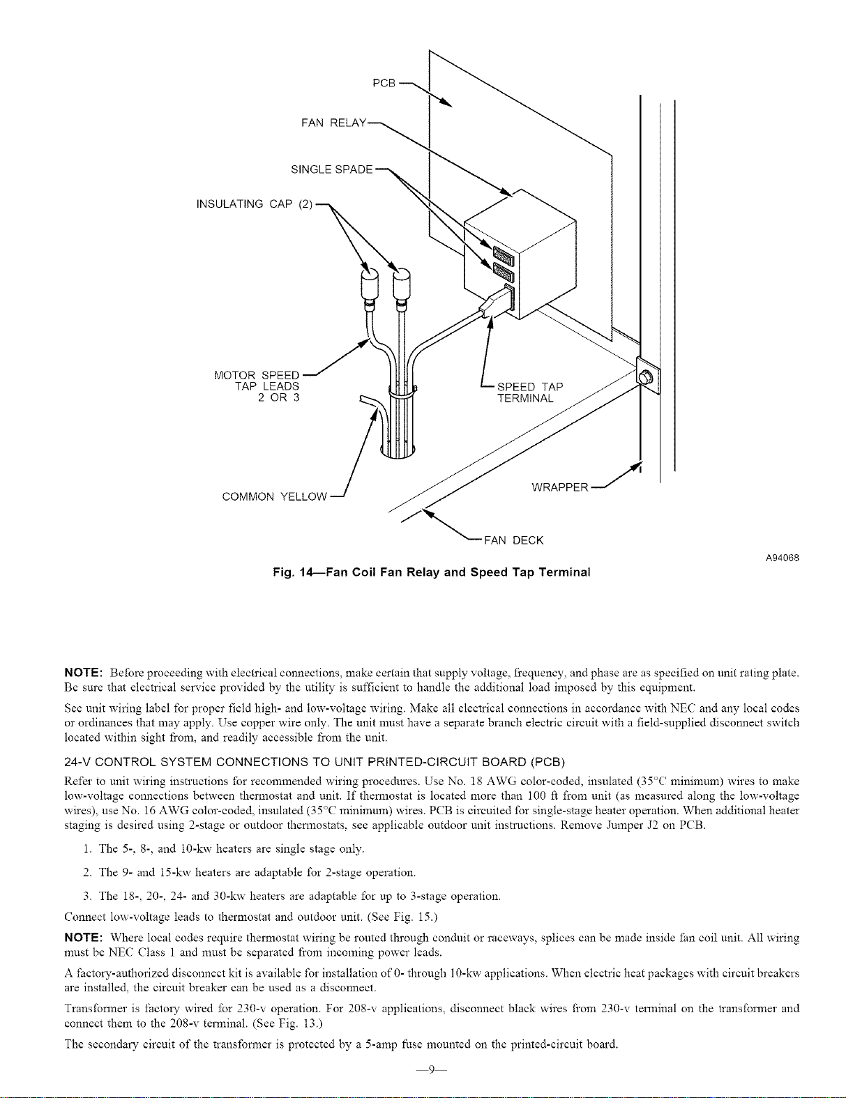
Fig. 14--Fan CoilFan Relay and Speed Tap Terminal
A94068
NOTE: Before proceeding with electrical connections, make certain that supply voltage, fi'equency, and phase are as specified on unit rating plate.
Be sure that electrical service provided by the utility is sufficient to handle the additional load imposed by this equipment.
See unit wiring label for proper field high- and low-voltage wiring. Make all electrical connections in accordance with NEC and any local codes
or ordinances that may apply. Use copper wire only. The unit must have a separate branch electric circuit with a field-supplied disconnect switch
located within sight f_com, and readily accessible from the unit.
24-V CONTROL SYSTEM CONNECTIONS TO UNIT PRINTED-CIRCUIT BOARD (PCB)
Refer to unit wiring instructions for recommended wiring procedures. Use No. 18 AWG color-coded, insulated (35°C mininmm) wires to make
low-voltage connections between thermostat and unit. If themmstat is located more than 100 ft from unit (as measured along the low-voltage
wires), use No. 16 AWG color-coded, insulated (35°C minimum) wires. PCB is circuited for single-stage heater operation. When additional heater
staging is desired using 2-stage or outdoor thermostats, see applicable outdoor unit instructions. Remove Jnmper J2 on PCB.
1. The 5-, 8-, and 10-kw heaters are single stage only.
2. The 9- and 15-kw heaters are adaptable for 2-stage operation.
3. The 18-, 20-, 24- and 30-kw heaters are adaptable for up to 3-stage operation.
Connect low-voltage leads to thermostat and outdoor unit. (See Fig. 15.)
NOTE: Where local codes require thermostat wiring be routed through conduit or raceways, splices can be made inside tan coil unit. All wiring
nmst be NEC Class 1 and must be separated from incoming power leads.
A _actory-authorized disconnect kit is available for installation of 0- through 10-kw applications. When electric heat packages with circuit breakers
are installed, the circuit breaker can be used as a disconnect.
Transfomler is factory wired for 230-v operation. For 208-v applications, disconnect black wires from 230-v terminal on the transformer and
connect them to the 208-v terminal. (See Fig. 13.)
The secondary circuit of the transformer is protected by a 5-amp fuse mounted on the printed-circuit board.
9
Loading ...
Loading ...
Loading ...