Loading ...
Loading ...
Loading ...
TH ERMOSTAT
[2>
[]-
[]
[]-
[]
[]
FAN COIL
'CONTROL'
RED R
G
c
BLU ODTS! ]
HEAT PUMP
(CONTROL
R
C
W2
O
Y
EMERGENCY HEAT RELAY
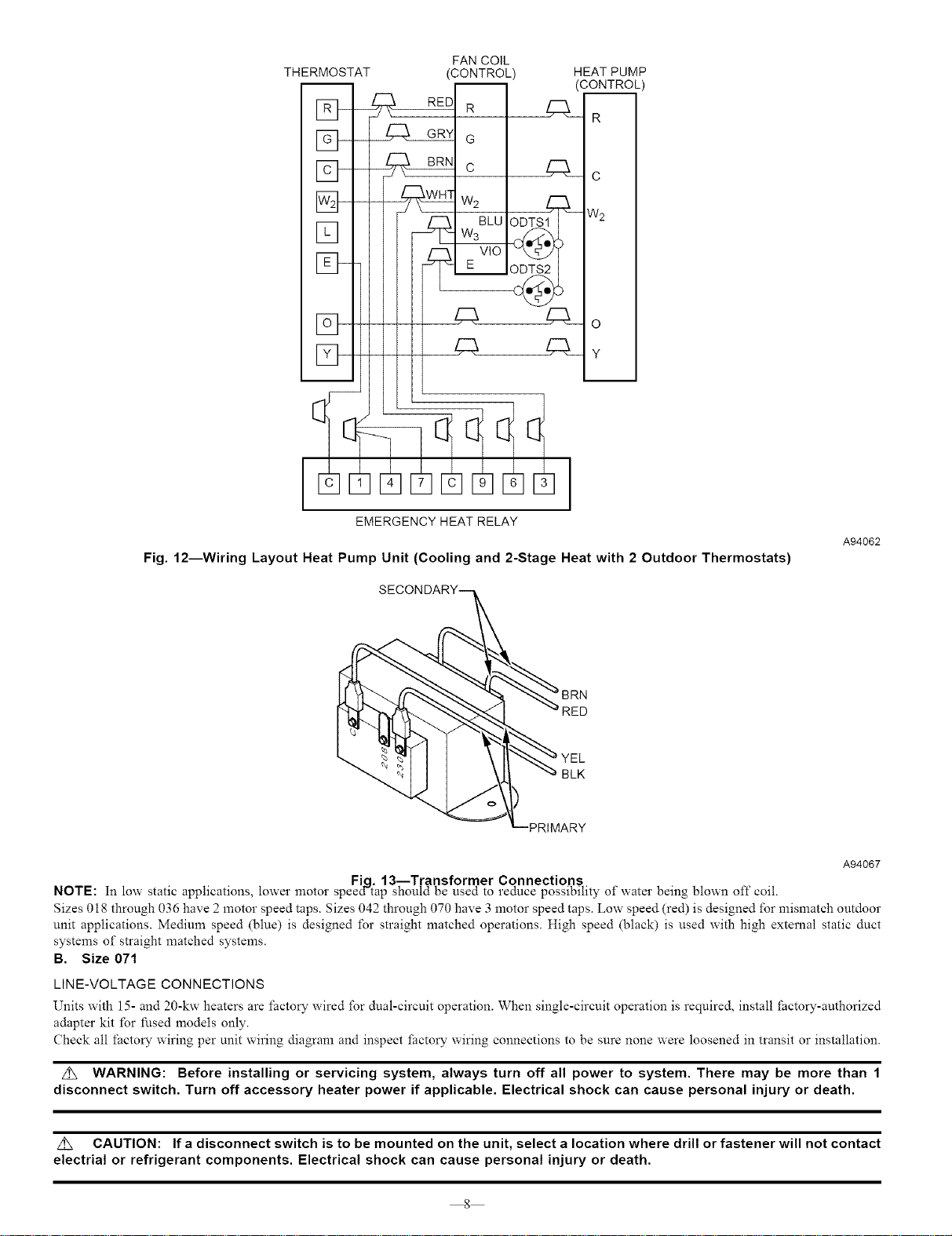
Fig. 12--Wiring Layout Heat Pump Unit (Cooling and 2-Stage Heat with 2 Outdoor Thermostats)
A94062
YEL
BLK
PRIMARY
A94067
Fie. 13--Transformer Connections
NOTE: In low static applications, lower motor speed'tap should be used to reduce possibility of water being blown oft" coil.
Sizes 018 through 036 have 2 motor speed taps. Sizes 042 through 070 have 3 motor speed taps. Low speed (red) is designed for mismatch outdoor
unit applications. Medium speed (blue) is designed for straight matched operations. High speed (black) is used with high external static duct
systems of straight matched systems.
B. Size 071
LINE-VOLTAGE CONNECTIONS
Units with 15- and 20-kw heaters are factory wired for dual-circuit operation. When single-circuit operation is required, install _actory-authorized
adapter kit for fused models only.
Check all factory wiring per unit wiring diagram and inspect factory wiring connections to be sure none were loosened in transit or installation.
z_ WARNING: Before installing or servicing system, always turn off all power to system. There may be more than 1
disconnect switch. Turn off accessory heater power if applicable. Electrical shock can cause personal injury or death.
z_ CAUTION: If a disconnect switch is to be mounted on the unit, select a location where drill or fastener will not contact
electrial or refrigerant components. Electrical shock can cause personal injury or death.
8
Loading ...
Loading ...
Loading ...