Loading ...
Loading ...
Loading ...
PROCEDURE 7--CONDENSATE DRAINS
--_ z_ CAUTION: The conversion of the fan coil to downflow requires special procedures for the condensate drains on both
A-coil and Slope units.
The vertical drains have an overflow hole between the primary and secondary drain holes. This hole is plugged for all
applications except downflow, but must be used for downflow.
During the conversion process, remove the plastic cap covering the vertical drains only and discard. Remove the plug from
the overflow hole and discard. At completion of the downflow installation, caulk around the vertical pan fitting to door joint
to retain the low air leak performance of the unit.
To connect drains the cap openings must be removed. Use a knife to start the opening near the tab and using pliers, pull the tab to remove the
disk. Clean the edge of the opening if necessary and install the condensate line. Finally caulk around the lines where they exit the fitting to retain
the low leak rating of the unit.
Units are equipped with primary and secondary 3/4 in. FPT &ain connections. For proper condensate line installation see Fig. 1, 2, 4, 5, and 6.
To prevent property damage and achieve optimum &ainage performance, BOTH primary and secondary &ain lines should be installed and include
properly-sized condensate traps. (See Fig. 17 and 19.) Factory-approved traps are available. It is recommended that PVC fittings be used on the
plastic condensate pan. Do not over-tighten. Finger-tighten plus i-i/2 turns. Use pipe dope.
z_x CAUTION: Shallow, running traps are inadequate and DO NOT allow proper condensate drainage. (See Fig. 18.)
NOTE: When connecting condensate &ain lines, avoid blocking filter access panel, thus preventing filter removal. After connection, prime both
primary and secondary condensate traps.
NOTE: If unit is located in or above a living space where damage may result from condensate overflow, a field-supplied, exterual condensate
pan should be installed underueath entire unit, and a secondary condensate line (with appropriate trap) should be run from unit into pan. Any
condensate in this exterual condensate pan should be drained to a noticeable place. As an alternative to using an exterual condensate pan, some
localities may allow the use of a separate 3/4 in. condensate line (with appropriate trap) to a place where condensate will be noticeable. The owner
of the structure must be informed that when condensate flows fi'om the secondary &ain or external condensate pan, unit reqnires servicing or water
damage will occur.
Install traps in condensate lines as close to coil as possible. (See Fig. 19.) Make sure that outlet of each trap is below its connection to condensate
pan to prevent condensate from overflowing the &ain pan. Prime all traps, test for leaks, and insulate traps if located above a living area.
Condensate drain lines should be pitched downward at a mininmm slope of 1 in. for every i0 ft of length.
Consult local codes for additional restrictions or precautions.
PROCEDURE 8--ACCESSORIES
A. Electric Heaters
See unit rating plate for factory approved electric heater kits. Follow installation instructions provided with kit.
B. Electronic Air Cleaner
SIZES 0"18--070
The Electronic Air Cleaner may be connected to fan coil as shown in Fig. 20. This method requires a field supplied 240vi120v 40va transformer
because it uses the 230-v fan coil power supply.
i- IE&NDISTR' OTOR
_-- PISTON BRASS
RETAINER HEX BODY
STRAINER
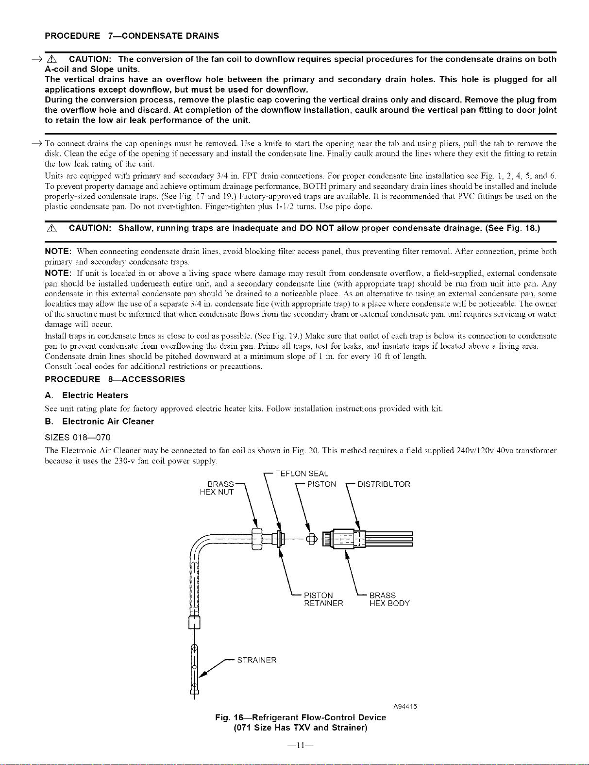
Fig. 16--Refrigerant Flow-Control Device
(071 Size Has TXV and Strainer)
11
A94415
Loading ...
Loading ...
Loading ...