
Installation Guide
Quality, Design and Innovation
home.liebherr.com/fridge-manuals
Contents
1 General safety instructions.......................... 2
2 Setup conditions........................................... 3
2.1 Space.................................................................... 3
2.2 Fitting the appliance into the kitchen unit..... 3
2.3 Setting up multiple appliances......................... 5
2.4 Electrical connection.......................................... 5
3 Installation dimensions................................ 5
4 Ventilation requirements.............................. 6
5 Transporting the appliance........................... 6
6 Unpacking the appliance.............................. 6
7 Mounting wall spacers.................................. 6
8 Setting up the device.................................... 6
9 Setting up the appliance level...................... 7
10 After setup..................................................... 7
11 Disposal of packaging................................... 7
12 Explanatory symbols used............................ 7
13 Reversing the door........................................ 8
13.1 Taking off the top soft stop mechanism......... 9
13.2 Removing the bottom soft stop damper......... 10
13.3 Disconnecting the cable connection............... 11
13.4 Removing the top door....................................... 12
13.5 Removing the bottom door................................ 13
13.6 Moving the upper bearing parts to the other
side........................................................................ 13
13.7 Moving the central bearing parts to the
other side.............................................................. 16
13.8 Moving the lower bearing parts to the other
side........................................................................ 16
13.9 Moving the door bearing parts to the other
side........................................................................ 17
13.10 Moving the handles to the other side*............ 18
13.11 Fitting the bottom door...................................... 19
13.12 Fitting the top door............................................. 19
13.13 Fitting the cable connection............................. 20
13.14 Aligning the doors............................................... 20
13.15 Fit the bottom soft stop mechanism............... 21
13.16 Fitting the top soft stop mechanism............... 21
14 Water connection*........................................ 22
15 Connecting the water supply*...................... 23
16 Water tank..................................................... 24
16.1 Inserting the water tank.................................... 24
17 Water filter*.................................................. 24
17.1 Installing the water filter................................... 24
18 Connecting the appliance............................. 25
Congratulations on the purchase of your new appli‐
ance. With this purchase, you have chosen all the
advantages of the latest refrigeration technology, guar‐
anteeing you a high-quality appliance with a long life
span and high operating safety.
The equipment of your appliance gives you the highest
level of day-to-day ease of operation.
Together we are making an active contribution to the
conservation of our environment by purchasing this
appliance which is manufactured in an environmentally
friendly process with the use of recyclable materials.
We hope you enjoy your new appliance.
The manufacturer is constantly working to improve all
types and models. Therefore, please be aware that we
reserve the right to make changes to the shape, equip‐
ment and technology.
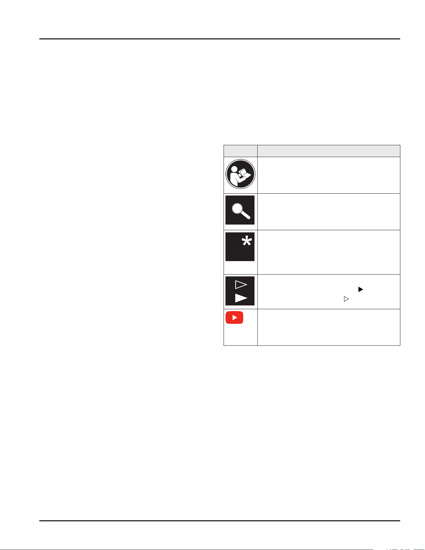
Symbol Explanation
Read instructions
Please read the information in these
instructions carefully to understand all of
the benefits of your new appliance.
Check appliance
Check all parts for transport damage. If you
have any complaints, please contact your
agent or customer service.
Differences
These instructions apply to a range of
models, so there may be differences.
Sections that apply to certain models only
are indicated by an asterisk (*).
Instructions and results
Instructions are marked with a
.
Results are marked with a
.
Videos
Videos about the appliances are available
on the YouTube channel of Liebherr-Hausg‐
eräte.
1 General safety instructions
-
Please keep this assembly manual in a safe
place so you can refer back to it at any time.
-
If you pass the appliance on, please hand
this assembly manual to the new owner.
-
Read this assembly manual before installa‐
tion and use in order to use the appliance
safely and correctly. Follow the instructions,
safety instructions and warning messages
included at all times. They are important for
ensuring you can operate and install the
appliance safely and without any problems.
-
First read the general safety instructions in
the “General safety instructions” section of
the operating instructions, which accom‐
pany these installation instructions, and
General safety instructions
2 * Depending on model and options
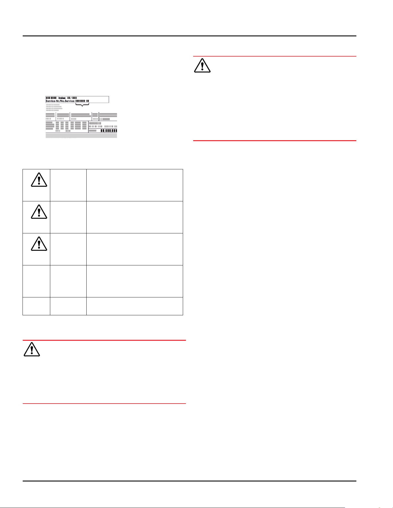
follow them. If you cannot find the oper‐
ating instructions, you can download the
operating instructions from the internet by
entering the service number at
home.liebherr.com/fridge-manuals. The
service number can be found on the serial
tag:
-
Observe the warning messages and other
detailed information in the other sections
when installing the appliance:
DANGER
indicates a hazardous situa‐
tion, which if not avoided, will
result in death or serious
injury.
WARNING indicates a hazardous situa‐
tion, which if not avoided,
could result in death or serious
injury.
CAUTION indicates a hazardous situa‐
tion, which if not avoided, will
result in minor or moderate
injury.
NOTICE indicates a hazardous situa‐
tion, which if not avoided,
could result in damage to prop‐
erty.
Note indicates useful advice and
tips.
2 Setup conditions
WARNING
Risk of fire due to moisture!
If live parts or the power cord get wet, this can cause a
short circuit.
u
The appliance is designed for use in enclosed
spaces. Do not operate the appliance in open space
or in damp areas or where there is spray.
Normal use
-
Only set up and use the appliance in enclosed
spaces.
2.1 Space
WARNING
Leaking refrigerant and oil!
Fire. The refrigerant contained within the appliance is
environmentally friendly, but flammable. The oil
contained within the appliance is flammable. Escaping
refrigerant and oil can ignite if they are of high enough
concentration and are exposed to an external heat
source.
u
Do not damage the pipelines of the coolant circuit
and the compressor.
-
If the appliance is installed in a very damp environ‐
ment condensate water may form on the outside of
the appliance.
Always make sure the installation area is well venti‐
lated. .
-
The more refrigerant there is in the appliance, the
larger the space it is installed in must be. If the
space is too small, any leak may create a flammable
mixture of gas and air. For every 8 g (0.02 lb) size of
the installation space must be at least 1 m
3
(35.5 ft
3
).
Specifications on the refrigerant in the appliance
can be found on the serial tag plate inside the appli‐
ance.
2.1.1 Installation surface
-
The floor of the installation site must be horizontal
and level.
-
The height of the appliance base must be the same
as the surrounding floor.
2.1.2 Installation position
-
Do not install the appliance in direct sunlight or next
to an oven, heater, or similar heat source.
-
Always stand the appliance backed directly to the
wall using the enclosed wall spacers (see below).
2.2 Fitting the appliance into the
kitchen unit
The appliance can be built into kitchen cabinets.
Setup conditions
* Depending on model and options 3
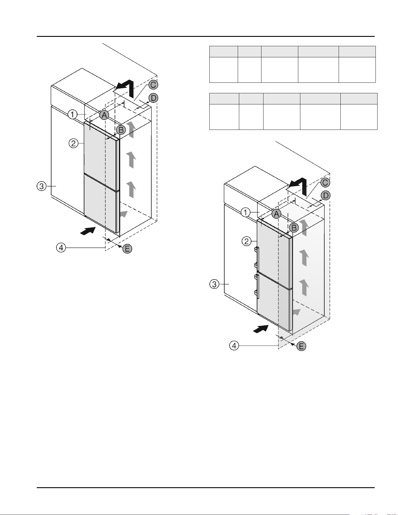
Fig. 1
(1)
Top cupboard* (B) Door depth*
(2) Appliance* (C) Ventilation cross-
section*
(3) Kitchen cabinet* (D) Distance to the rear of
the appliance*
(4) Wall* (E) Distance to the side of
the appliance*
(A) Appliance depth*
Set up the appliance directly next to the kitchen
cabinet Fig. 1 (3).*
There must be a ventilation shaft at the depth Fig. 1 (D)
of the back of the top cupboard over the entire width
of the top cupboard.*
The cross section of the ventilation gap Fig. 1 (C) must
be maintained below the ceiling.*
If the appliance is installed with the hinges next to a
wall Fig. 1 (4), the distance between the appliance and
the wall must be at least 13 mm (0.51 in).*
If the appliance is installed with the hinges next to a
wall Fig. 1 (4), the distance between the appliance and
the wall must be at least 20 mm (0.79 in).*
In order to be able to fully open the door, the appliance
must protrude by the depth Fig. 1 (B) of the door from
the front of the kitchen cabinet. Regardless of the
depth of the kitchen cabinets Fig. 1 (3) and use of wall
spaces, the appliance can protrude further.*
A*
B* C* D* E*
675 mm
26.57 in
x
75 mm
2.95 in
Min.
300 cm
2
(46.5 in
2
)
Min.
50 mm
(1.97 in)
Min.
13 mm
(0.51 in)
Appliances without handle / with recessed grip
A* B* C* D* E*
682 mm
26.85 in
x
82 mm
3.23 in
Min.
300 cm
2
(46.5 in
2
)
Min.
50 mm
(1.97 in)
Min.
20 mm
(0.79 in)
Appliances with recessed grip and glass/stone front
Fig. 2
(1)
Top cabinet* (B) Door depth*
(2) Appliance* (C) Ventilation cross-
section*
(3) Kitchen cabinet* (D) Distance to the rear of
the appliance*
(4) Wall* (E) Distance to the side of
the appliance*
(A) Appliance depth*
Set up the appliance directly next to the kitchen
cabinet Fig. 2 (3).*
There must be a ventilation shaft at the depth Fig. 2 (D)
of the back of the top cupboard over the entire width
of the top cupboard.*
The cross section of the ventilation gap Fig. 2 (C) must
be maintained below the ceiling.*
Setup conditions
4 * Depending on model and options
If the appliance is installed with the hinges next to a
wall Fig. 2 (4), the distance between the appliance and
the wall must be at least 57 mm (2.24 in). This is how
far the handle protrudes when the door is open.*
In order to be able to fully open the door, the appliance
must protrude by the depth Fig. 2 (B) of the door from
the front of the kitchen cabinet. Regardless of the
depth of the kitchen cabinets Fig. 2 (3) and use of wall
spaces, the appliance can protrude further.*
A* B* C* D* E*
675 mm
26.57 in
x
75 mm
2.95 in
Min.
300 cm
2
(46.5 in
2
)
Min.
50 mm
(1.97 in)
Min.
57 mm
(2.24 in)
Appliances with lever handle
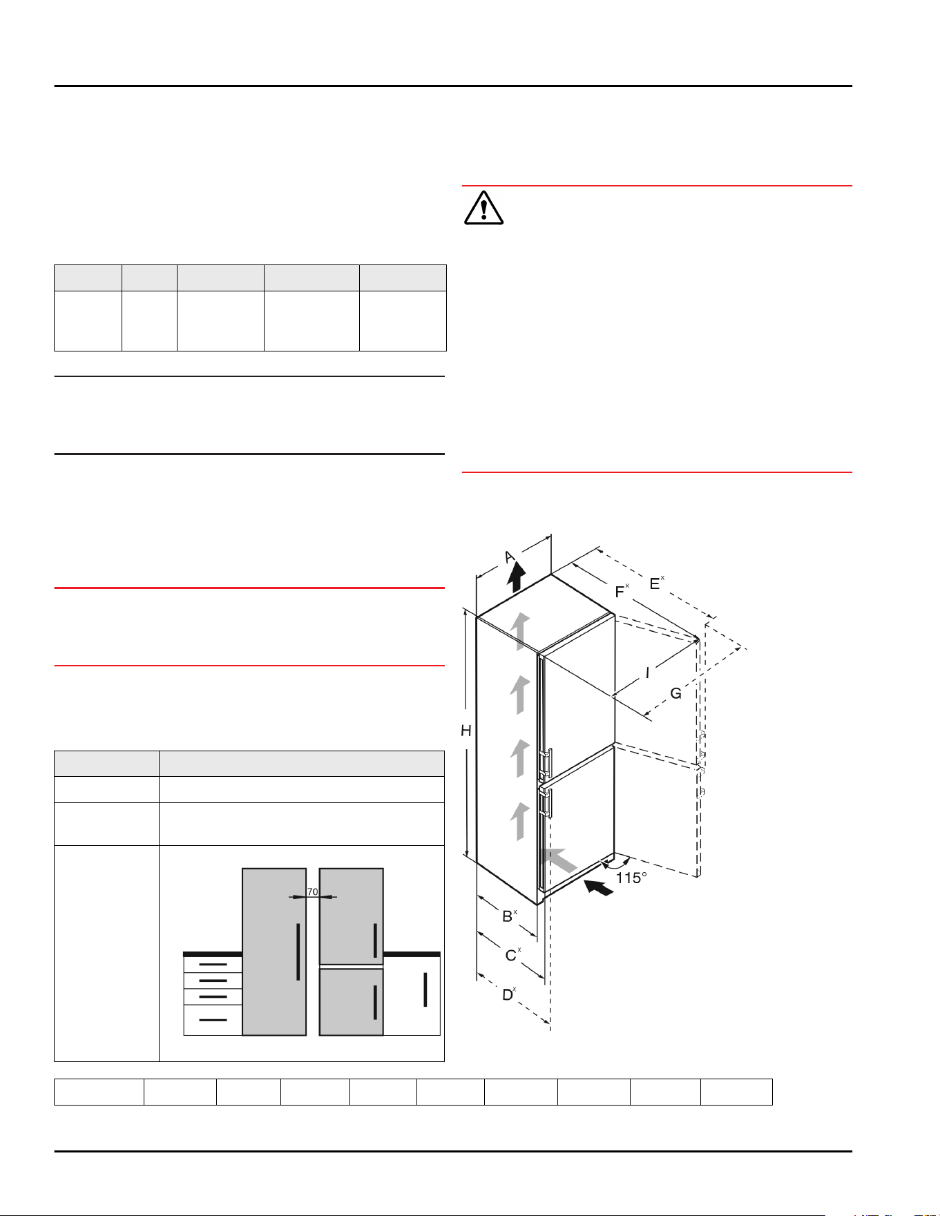
Note
A set for restricting the door opening angle to 90° can
be acquired from Customer Services for appliances
with soft closing.
Ensure that the following conditions are met:
-
Recess dimensions are adhered to .
-
Ventilation requirements are complied with
(see 4 Ventilation requirements) .
2.3 Setting up multiple appliances
NOTICE
Risk of damage caused by water condensate!
u
Do not install this device directly beside another
fridge/freezer compartment.
These appliances are designed for different types of
installation. Only combine appliances if the appliances
are designed for this. The following table shows the
installation options by model:
Setup type
Model
Single All models
Side-by-Side
(SBS)
Model that start with S....
Side-by-side
with a
distance of
70 mm
(2.76 in)
between
appliances
Otherwise
condensa‐
tion will build
up between
the units.
All models without side wall heating
Fig. 3
Assemble appliances according to separate installation
instructions.
2.4 Electrical connection
WARNING
Danger of fire due to incorrect positioning!
If the power supply cable or plug touches the back of
the appliance, the vibration can damage the power
supply cable or the plug resulting in a short circuit.
u
Make sure the power supply cable is not trapped
under the appliance when you position the appli‐
ance.
u
Install the appliance so that it does not touch any
plugs or power cables.
u
Do not connect any appliances to sockets in the area
of the back of the appliance.
u
Do not place and operate power strips/power
distributors and other electronic devices (such as
halogen transformers) at the back of the appliances.
3 Installation dimensions
Fig. 4
H
A B C D I G F E
Installation dimensions
* Depending on model and options 5
C5250 1855 mm
73.03 in
597 mm
23.5 in
611 mm
24.06 in
x
675 mm
26.57 in
x
719 mm
28.31 in
x
846 mm
33.31 in
882 mm
34.72 in
1178 mm
46.38 in
x
1186 mm
46.69 in
x
SC5781 2015 mm
79.33 in
597 mm
23.5 in
611 mm
24.06 in
x
675 mm
26.57 in
x
719 mm
28.31 in
x
846 mm
33.31 in
882 mm
34.72 in
1178 mm
46.38 in
x
1186 mm
46.69 in
x
SCB5790IM 2015 mm
79.33 in
597 mm
23.5 in
611 mm
24.06 in
x
675 mm
26.57 in
x
719 mm
28.31 in
x
846 mm
33.31 in
882 mm
34.72 in
1178 mm
46.38 in
x
1186 mm
46.69 in
x
SC7751 2015 mm
79.33 in
747 mm
29.41 in
610 mm
24.02 in
x
675 mm
26.57 in
x
719 mm
28.31 in
x
1059 mm
41.69 in
1096 mm
43.15 in
1314 mm
51.73 in
x
1322 mm
52.05 in
x
SCB7760IM 2015 mm
79.33 in
747 mm
29.41 in
610 mm
24.02 in
x
675 mm
26.57 in
x
719 mm
28.31 in
x
1059 mm
41.69 in
1096 mm
43.15 in
1314 mm
51.73 in
x
1322 mm
52.05 in
x
CB7790IM 2015 mm
79.33 in
747 mm
29.41 in
610 mm
24.02 in
x
675 mm
26.57 in
x
— 1059 mm
41.69 in
— 1314 mm
51.73 in
x
—
x
For appliances with supplied wall spacers, the dimen‐
sions must be increased by 15 mm (0.59 in)
(see 7 Mounting wall spacers) .
4 Ventilation requirements
NOTICE
Risk of damage due to overheating in the case of insuf‐
ficient ventilation!
In the case of insufficient ventilation, the compressor
can be damaged.
u
Make sure there is sufficient ventilation.
u
Observe the ventilation requirements.
If the appliance is integrated in a fitted kitchen, the
following ventilation requirements must be met:
-
The spacing fins on the back of the appliance are
used to ensure sufficient ventilation. These must not
lie in cavities or recesses in their final installation
position.
-
Basically, the larger the ventilation gap, the more
energy the appliance saves during operation.
5 Transporting the appliance
u
On initial setup: Transport the appliance in its pack‐
aging.
u
When transporting after initial setup (e.g. reloca‐
tion): Transport the appliance unloaded.
u
Transport the appliance upright.
u
Use two people when transporting the appliance.
6 Unpacking the appliance
If the appliance is damaged check with the supplier
immediately before connecting it.
u
Check the appliance and packaging for damage
during transport. If you suspect any damage, please
contact your supplier immediately.
u
Remove all materials that could prevent it from
being installed properly or prevent proper ventilation
from the back or the side panels of the appliance.
u
Remove all protective films from the appliance. Do
not use sharp or pointed objects for this.
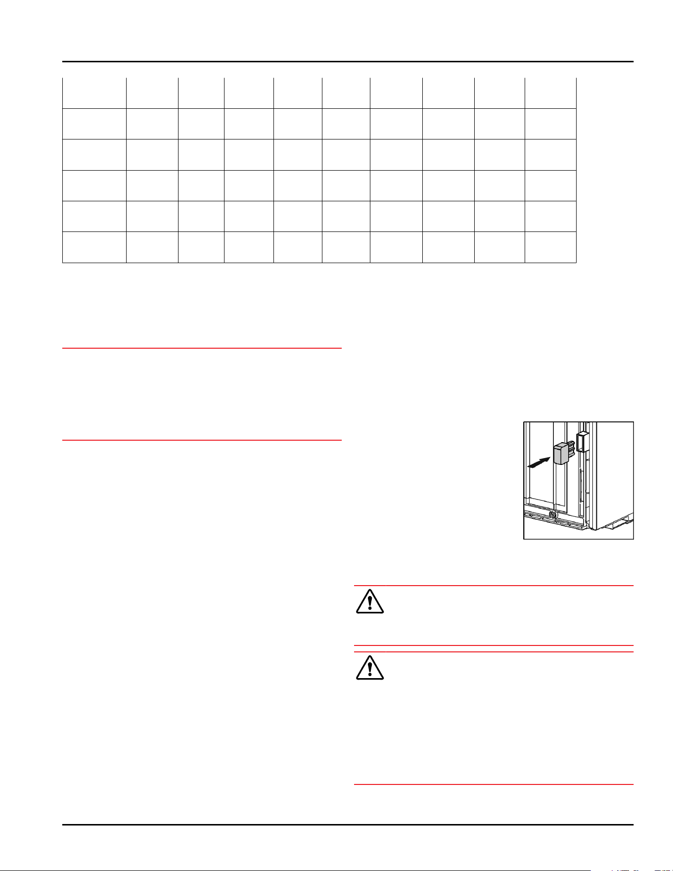
7 Mounting wall spacers
The spacers must be used in order to reach the
declared energy consumption levels as well as to avoid
the formation of condensate water at high levels of
ambient humidity. These will extend the depth of the
appliance by approx. 15 mm (0.59 in). The appliance is
fully functional if the spacers are not used, but it will
consume slightly more energy.
u
If wall spacers are supplied
with an appliance, these wall
spaces must be mounted on
the left and right of the back
of the appliance.
8 Setting up the device
CAUTION
Risk of personal injury!
u
Have two people move this appliance into place.
CAUTION
Risk of injury and damage!
The door can strike against the wall, which would
damage it. In the case of glass doors, the broken glass
may cause injury!
u
Protect the door from striking against the wall. Place
a door stopper, e.g. a felt stopper, on the wall.
u
A device that limits door opening to 90° can be
ordered from a qualified service provider.
Ventilation requirements
6 * Depending on model and options
WARNING
Unstable appliance!
Risk of injury and damage. The appliance can tip over.
u
Secure the appliance according to the operating
instructions.
WARNING
Danger of fire and damage!
u
Do not place devices that give off heat, e.g. micro‐
waves, toasters, etc. on the appliance.
Make sure that the following requirements are fulfilled:
q
Only move the appliance when it is not loaded.
q
Only set up the appliance when someone is present
to help you.
9 Setting up the appliance level
CAUTION
Risk of injury or damage from the appliance tipping or
the door falling open!
If the additional adjustable foot on the base support is
not correctly positioned on the floor, there is a risk of
the door falling open or the appliance tipping. This can
lead to injury or property damage.
u
Unscrew the additional adjustable foot on the
support until it reaches the floor.
u
Then turn it another 90°.
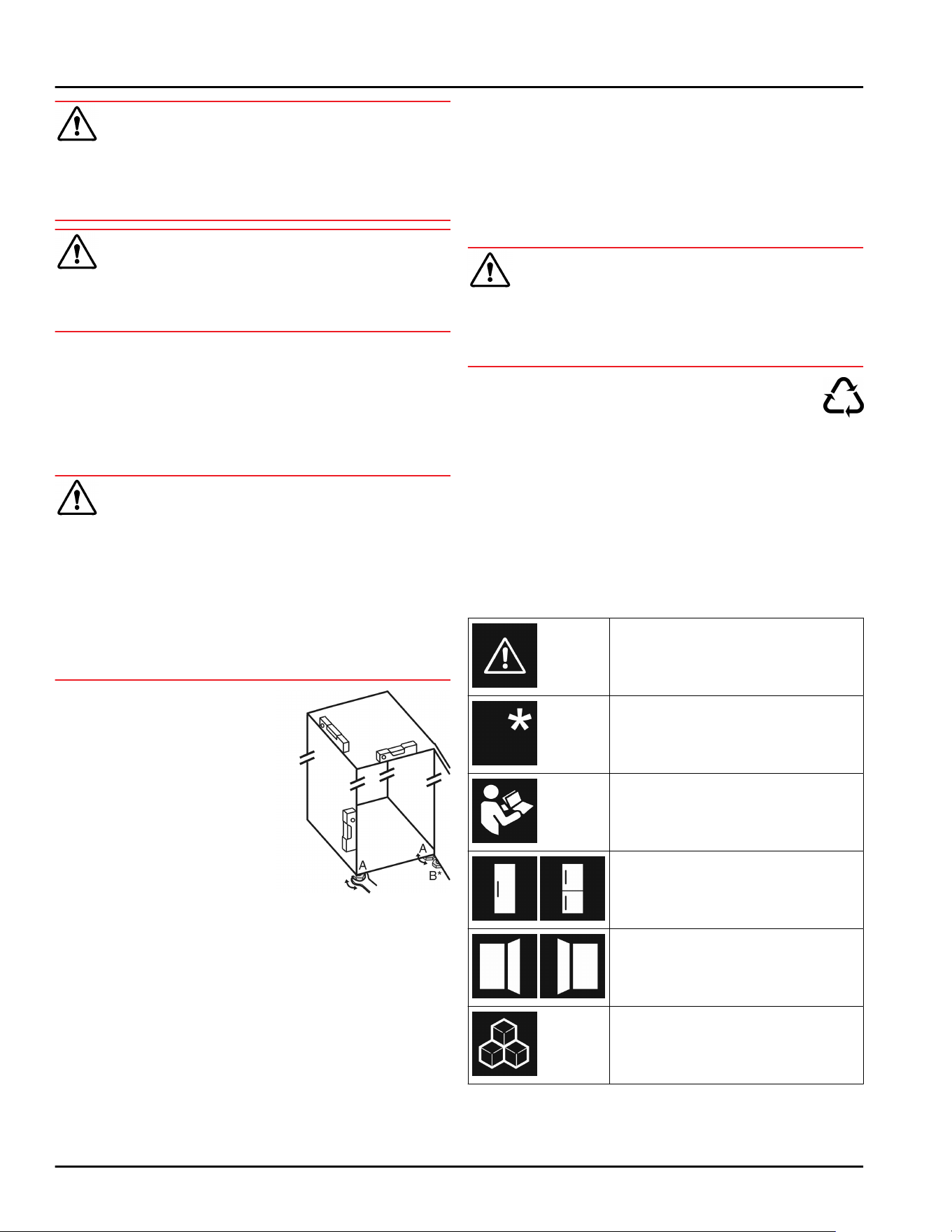
u
Align the appliance so that
it stands firmly and by
applying the accompa‐
nying spanner to the
adjustable height feet (A)
and using a spirit level.
u
Then prop up the door:
Lower the adjustable foot
on the bearing bracket (B)
until it contacts the floor,
then turn it an additional
90°.
u
Then prop up the door: Screw out the adjustable foot
on the bearing bracket (B) using the open-ended
wrench SW10 until it comes into contact with the
floor, then turn an additional 90°.
10 After setup
u
Pull off the protective film from the outside of the
housing.
u
Pull off the protective film from the trim strips.
u
Pull off the protective film from the trim strips and
drawer fronts.
u
Pull off the protective film from the stainless steel
rear panel.
u
Remove all transport packaging.
u
Clean the appliance .
u
Make a note of type (model, number), appliance
designation, appliance/serial no., date of purchase,
and dealer address in the designated fields .
11 Disposal of packaging
WARNING
Danger of suffocation from packaging materials and
films!
u
Do not allow children to play with packaging mate‐
rials.
The packaging is made from recyclable mate‐
rials:
-
Corrugated card/cardboard
-
Parts made of foamed polystyrene
-
Films and bags from polyethylene
-
Packing bands from polypropylene
-
Wood frame nailed together with a polyethy‐
lene window*
u
Take the packaging material to an official collection
point.
12 Explanatory symbols used
There is the risk of injury when
doing this! Obey the safety
instructions!
These instructions apply to
several models. Only perform this
step if it applies to your appli‐
ance.
To install, please follow the
detailed description in the Guide.
This section applies either to a
single-door appliance or a double-
door appliance.
Choose one of the options: Appli‐
ance with right-hinged door or
appliance with left-hinged door.
Installation step necessary with
IceMaker and/or InfinitySpring.
Setting up the appliance level
* Depending on model and options 7
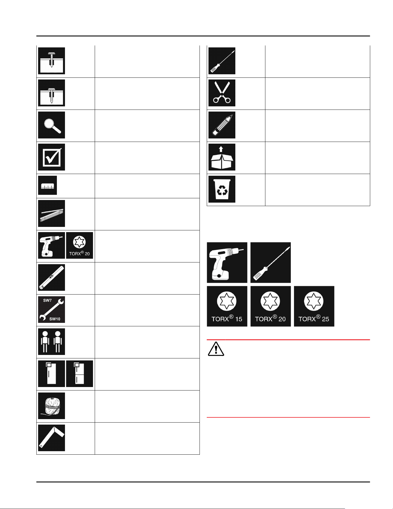
Loosen or tighten screws slightly.
Tighten the screws fully.
Check to see if the next step
applies for your model.
Check the components are in
correctly.
Measure the specified measure‐
ment and adjust if necessary.
Installation tool: Meter stick
Tool for assembly: Cordless
screwdriver and attachments
Tool for assembly: Spirit level
Tool for assembly: Size 7 and size
10 spanner
Two people are required for this
step.
This step takes place at the
selected location of the appli‐
ance.
Aid for assembly: String
Aid for assembly: Square
Aid for assembly: Screwdriver
Aid for assembly: Scissors
Aid for assembly: Non-permanent
marker pen
Accessory kit: Remove compo‐
nents
Dispose of components that are
no longer needed.
13 Reversing the door
Tools
Fig. 5
WARNING
Danger of injury due to door falling out!
If the bearing parts are not screwed on tightly enough,
the door may fall out. This can result in serious injuries.
In addition, the door may not close causing the appli‐
ance to cool improperly.
u
Screw the bearing brackets/bearing pins on tightly
using 4 Nm (3 lb-ft) .
u
Check all screws and retighten them if necessary.
Reversing the door
8 * Depending on model and options
NOTICE
Risk of damage to side-by-side appliances caused by
condensate!
Certain appliances can be set up as side-by-side
combinations (two appliances beside one another).
If your appliance is a side-by-side appliance:
u
Install the SBS combination in accordance with the
accompanying sheet.
If the configuration of appliances is specified:
u
Do not change the door stop.
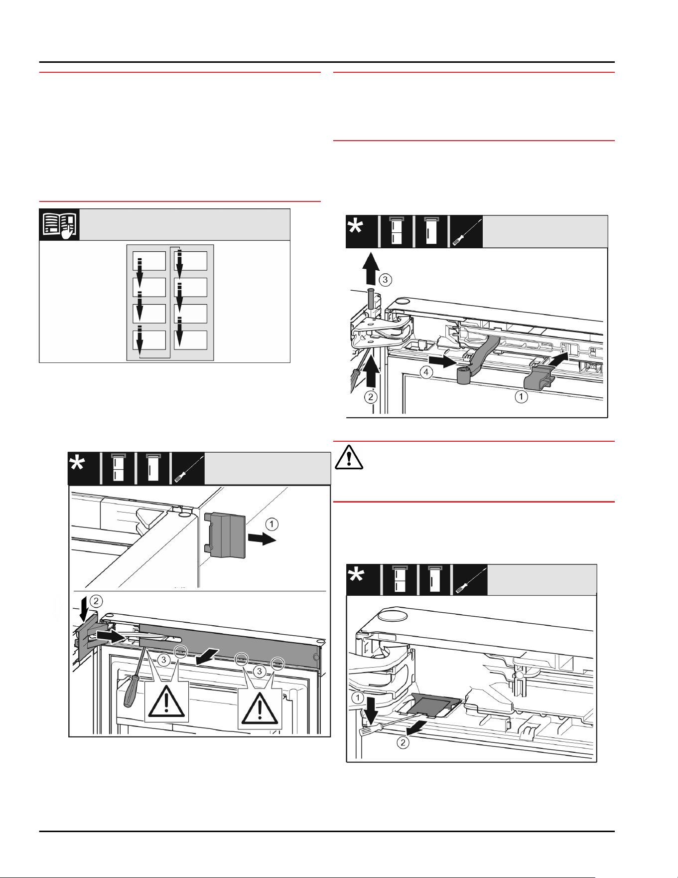
Fig. 6
Observe the reading direction.
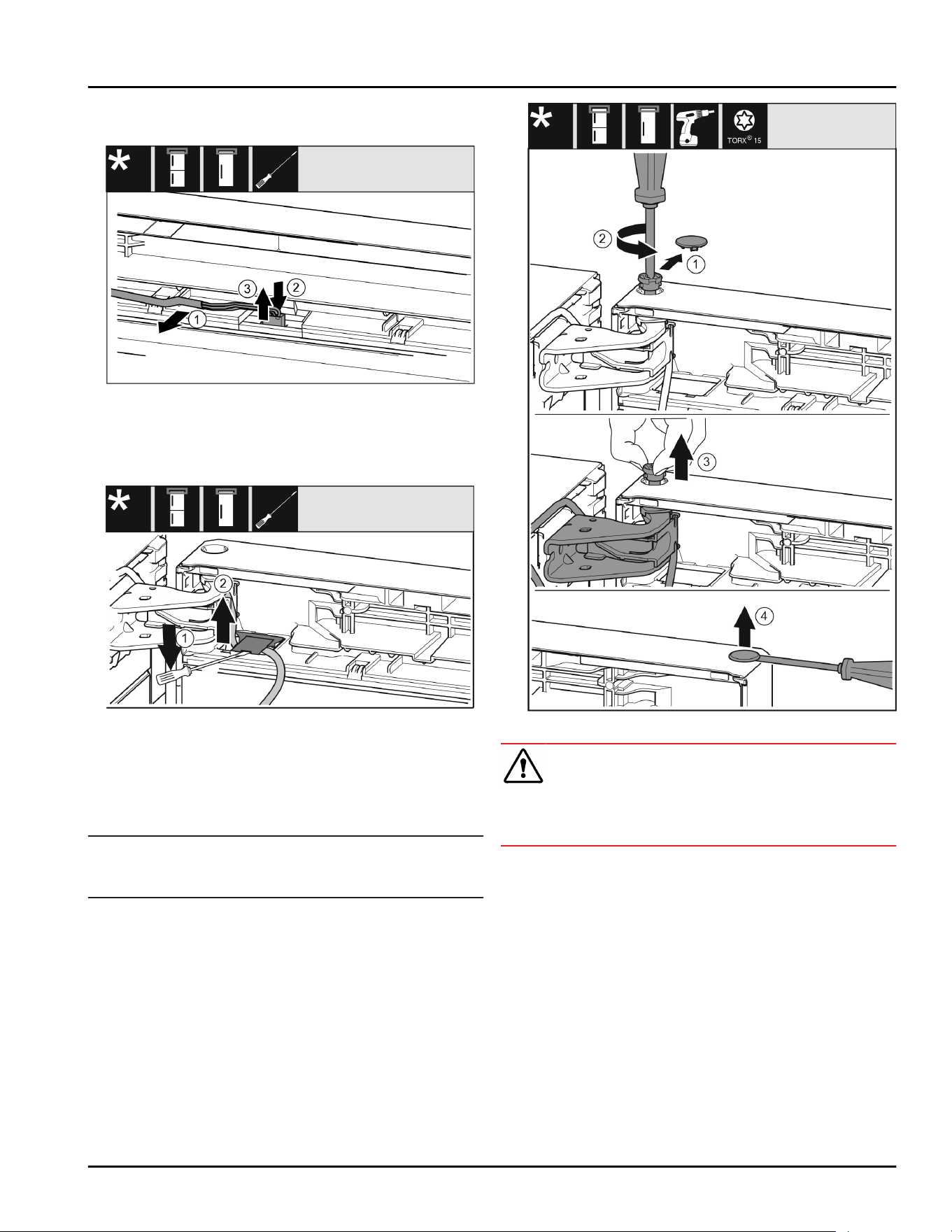
13.1 Taking off the top soft stop
mechanism
Fig. 7
u
Open the top door.
NOTICE
Risk of damage!
If the door seal is damaged the door may not close
properly and the level of cooling is insufficient.
u
Do not damage the door seal with the screwdriver!
u
Remove the outer cover. Fig. 7 (1)
u
Disengage and release the bearing bracket cover.
Remove the bearing bracket cover. Fig. 7 (2)
u
Unlatch the panel with a slotted screwdriver and
swivel it to one side. Fig. 7 (3)
Fig. 8
CAUTION
Crushing hazard from the folding bracket!
u
Engage the locking device.
u
Engage the locking device in the opening. Fig. 8 (1)
u
Unscrew the bolt with a screwdriver. Fig. 8 (2)
u
Remove the bolt upwards. Fig. 8 (3)
u
Turn the hinge in the direction of the door. Fig. 8 (4)
Fig. 9
u
Unlatch the cover with a slotted screwdriver and lift
it up. Fig. 9 (1)
u
Take out the cover. Fig. 9 (2)
Reversing the door
* Depending on model and options 9
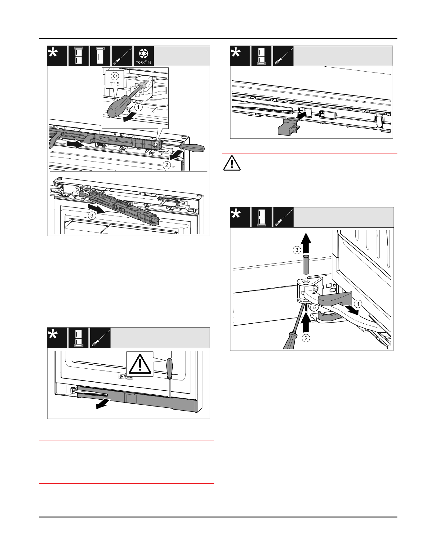
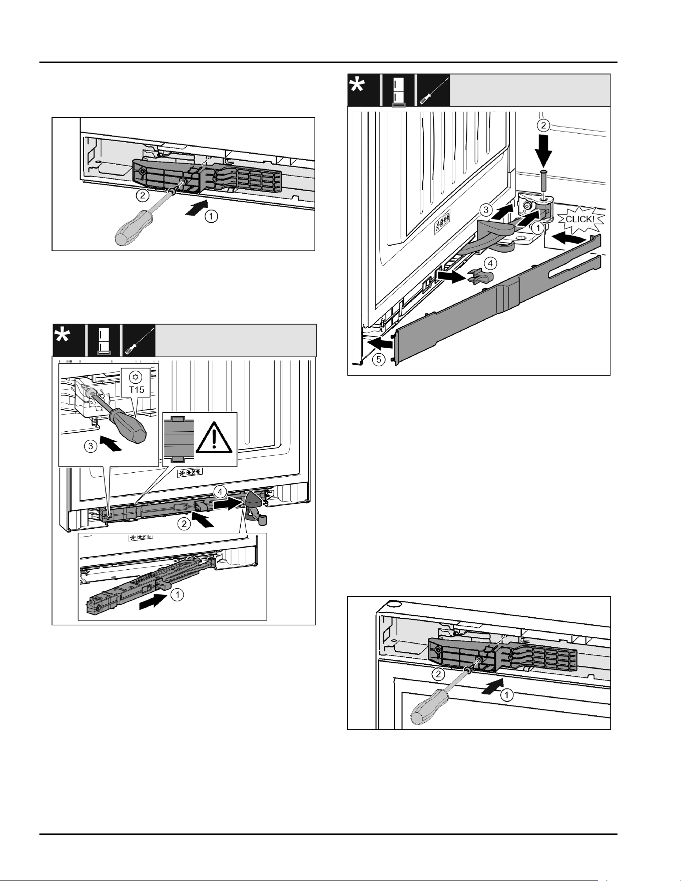
Fig. 10
u
Loosen the soft stop unit screw with a T15 screw‐
driver approx. 14 mm (0.55 in). Fig. 10 (1)
u
Insert a screwdriver behind the soft stop mechanism
on the handle side and rotate the unit forwards.
Fig. 10 (2)
u
Pull out the soft stop unit. Fig. 10 (3)
13.2 Removing the bottom soft stop
damper
Fig. 11
u
Open the bottom door.
NOTICE
Risk of damage!
If the door seal is damaged the door may not close
properly and the level of cooling is insufficient.
u
Do not damage the door seal with the screwdriver!
u
Unlatch the panel with a slotted screwdriver and
swivel it to one side Fig. 11 ().
Fig. 12
CAUTION
Crushing hazard from the folding bracket!
u
Engage the locking device.
u
Engage the locking device in the opening Fig. 12 ().
Fig. 13
u
Remove the bearing bracket cover and push it along
the hinge. Fig. 13 (1)
u
Lift the bolt with a finger or screwdriver from below.
Fig. 13 (2)
u
Insert the screwdriver under the bolt head and
remove it. Fig. 13 (3)
Reversing the door
10 * Depending on model and options
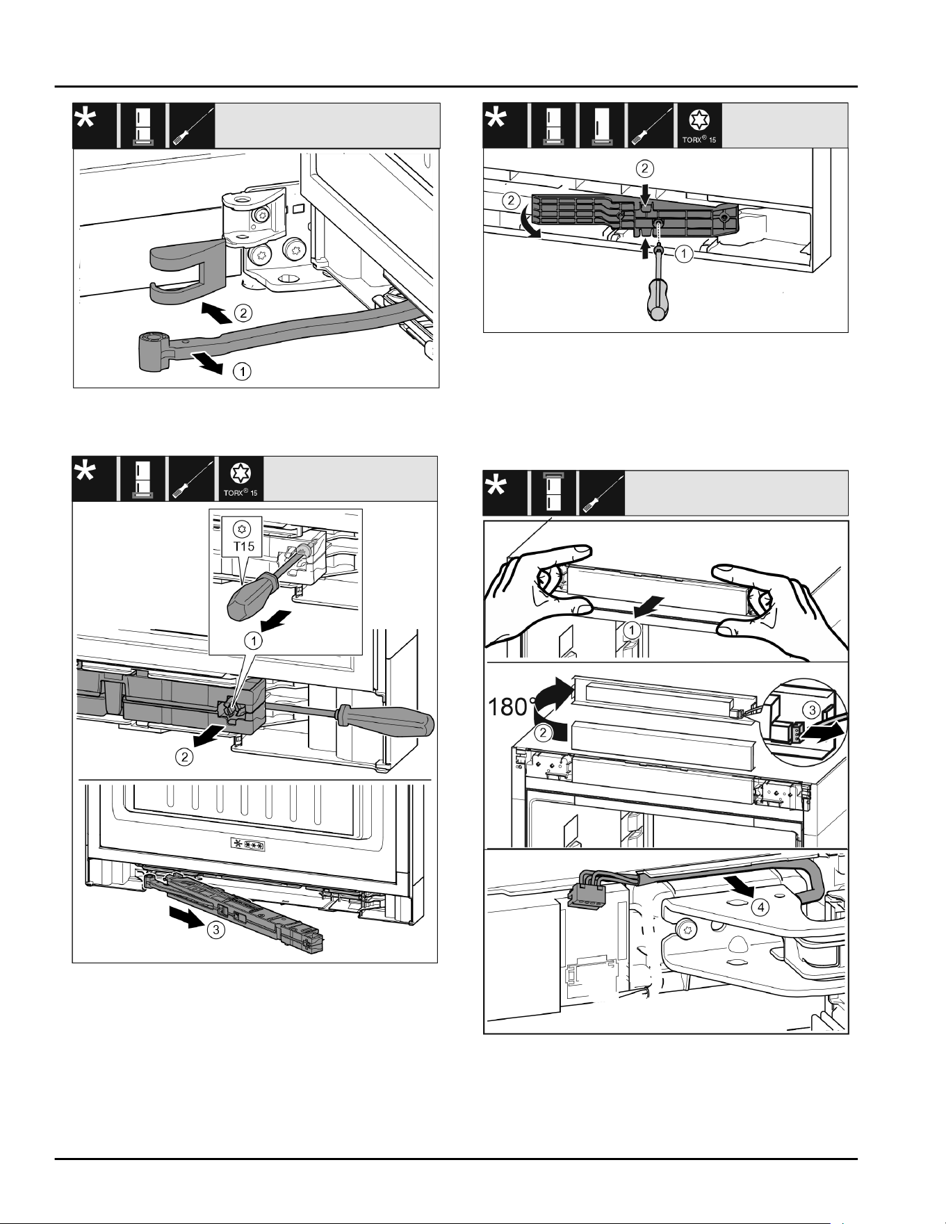
Fig. 14
u
Turn the hinge in the direction of the door. Fig. 14 (1)
u
Remove the bearing bracket cover. Fig. 14 (2)
Fig. 15
u
Undo the soft stop unit screw with a T15 screwdriver
approx. 14 mm (0.55 in). Fig. 15 (1)
u
Insert the screwdriver on the handle side behind the
soft stop unit. Turn the unit forward. Fig. 15 (2)
u
Pull out the unit. Fig. 15 (3)
u
Place the soft stop mechanism to one side.
Fig. 16
*
u
Loosen the screws with a T15 screwdriver. Fig. 16 (1)*
u
Pull out the adapter. Fig. 16 (2)*
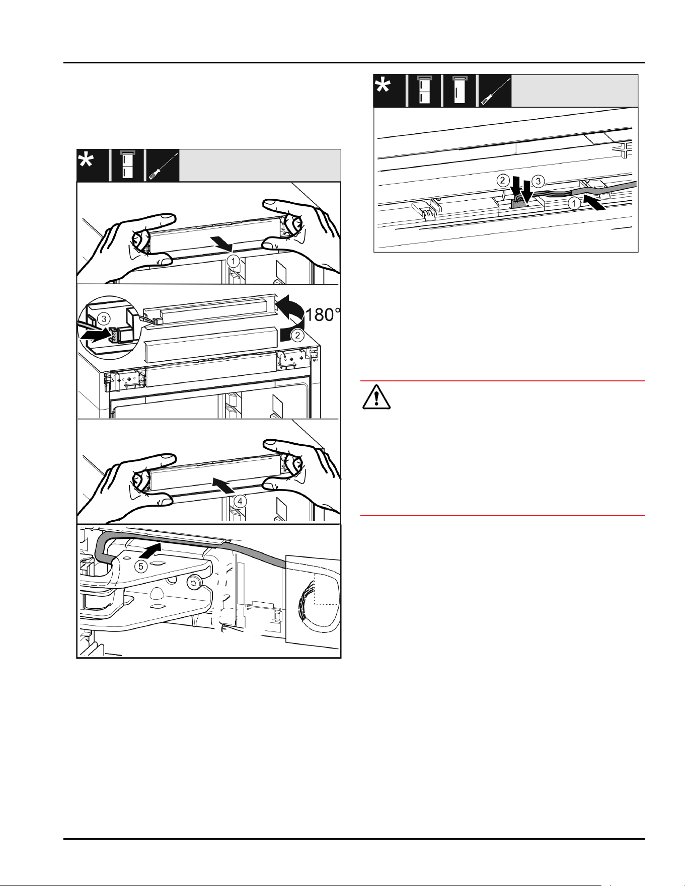
13.3 Disconnecting the cable connec‐
tion
Fig. 17
u
Loosen the control panel of the appliance carefully
to the front. Fig. 17 (1)
u
Turn the control panel up by 180°. Fig. 17 (2)
u
Press the latching lug backward and pull out the
plug carefully. Fig. 17 (3)
Reversing the door
* Depending on model and options 11
u
Carefully remove the cable over the bearing bracket
from the guide. Fig. 17 (4)
Fig. 18
u
Carefully remove the gray cable from the guide in
the door. Fig. 18 (1)
u
Press the lug behind the plug backward. Fig. 18 (2)
u
Carefully pull out the plug upward. Fig. 18 (3)
Fig. 19
u
Lift up the cover with the slotted screwdriver and
pull it out. Fig. 19 (1)
u
Pull out the cable. Fig. 19 (2)
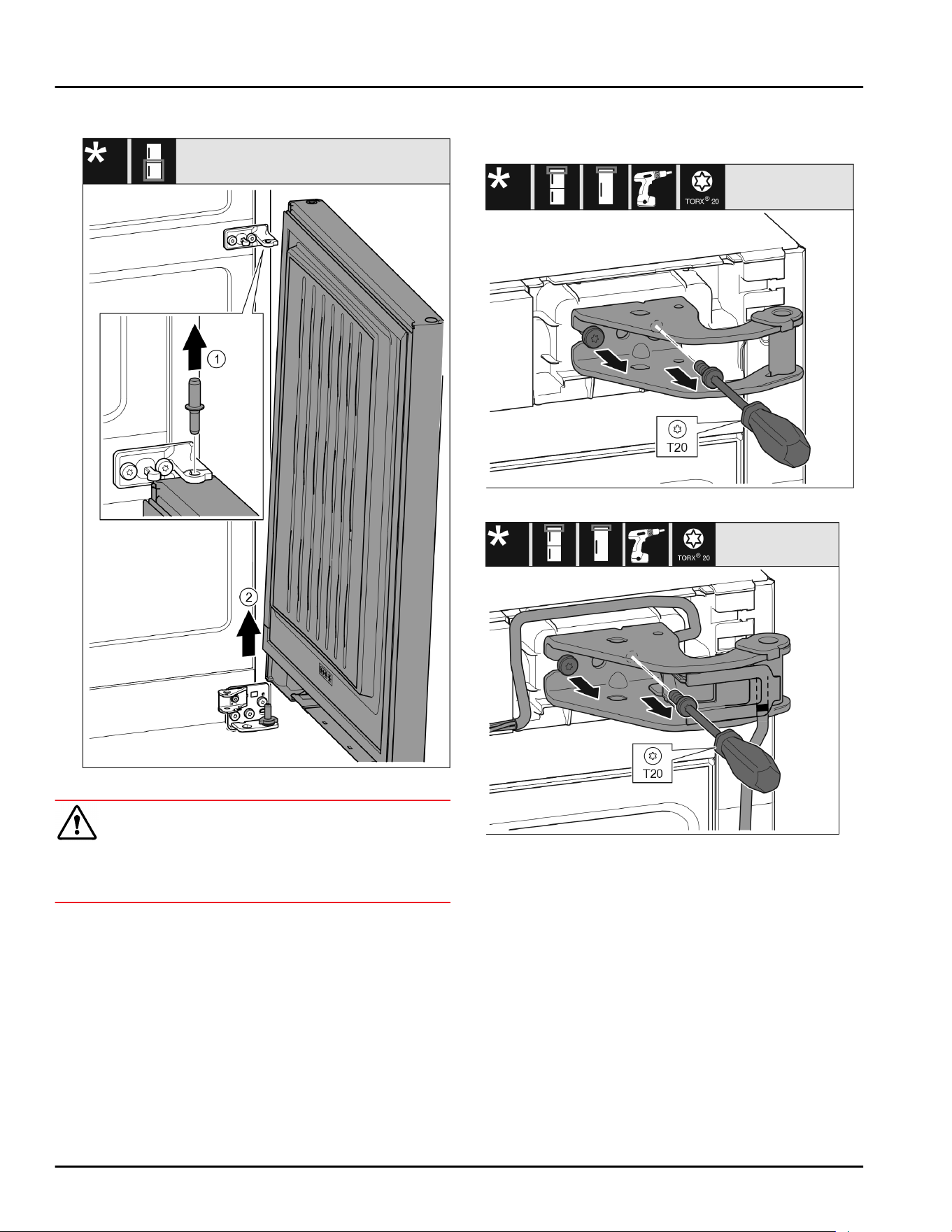
13.4 Removing the top door
Note
u
To prevent food items from falling out, take all food
out of the door racks before removing the door.
Fig. 20
CAUTION
Risk of injury if the door tips out!
u
Keep a steady grip on the door.
u
Set the door down carefully.
u
Carefully remove the protective cover. Fig. 20 (1)
u
Loosen the bolts slightly with a T15 screwdriver.
Fig. 20 (2)
u
Hold the door and remove the bolts with your
fingers. Fig. 20 (3)
u
Lift the door and place it to one side.
u
Carefully lift the plugs out of the door bearing bush
with a slotted screwdriver and remove them.
Fig. 20 (4)
Reversing the door
12 * Depending on model and options
13.5 Removing the bottom door
Fig. 21 *
CAUTION
Risk of injury if the door tips out!
u
Keep a steady grip on the door.
u
Set the door down carefully.
u
Pull out the bolts toward the top. Fig. 21 (1)*
u
Swing the door out, pull it upward and set it aside.
Fig. 21 (2)*
13.6 Moving the upper bearing parts
to the other side
Fig. 22
Fig. 23
u
Remove both screws with a T20 screwdriver.
u
Lift and remove the bearing bracket.
u
Lift and remove the bearing bracket and cable.
Reversing the door
* Depending on model and options 13
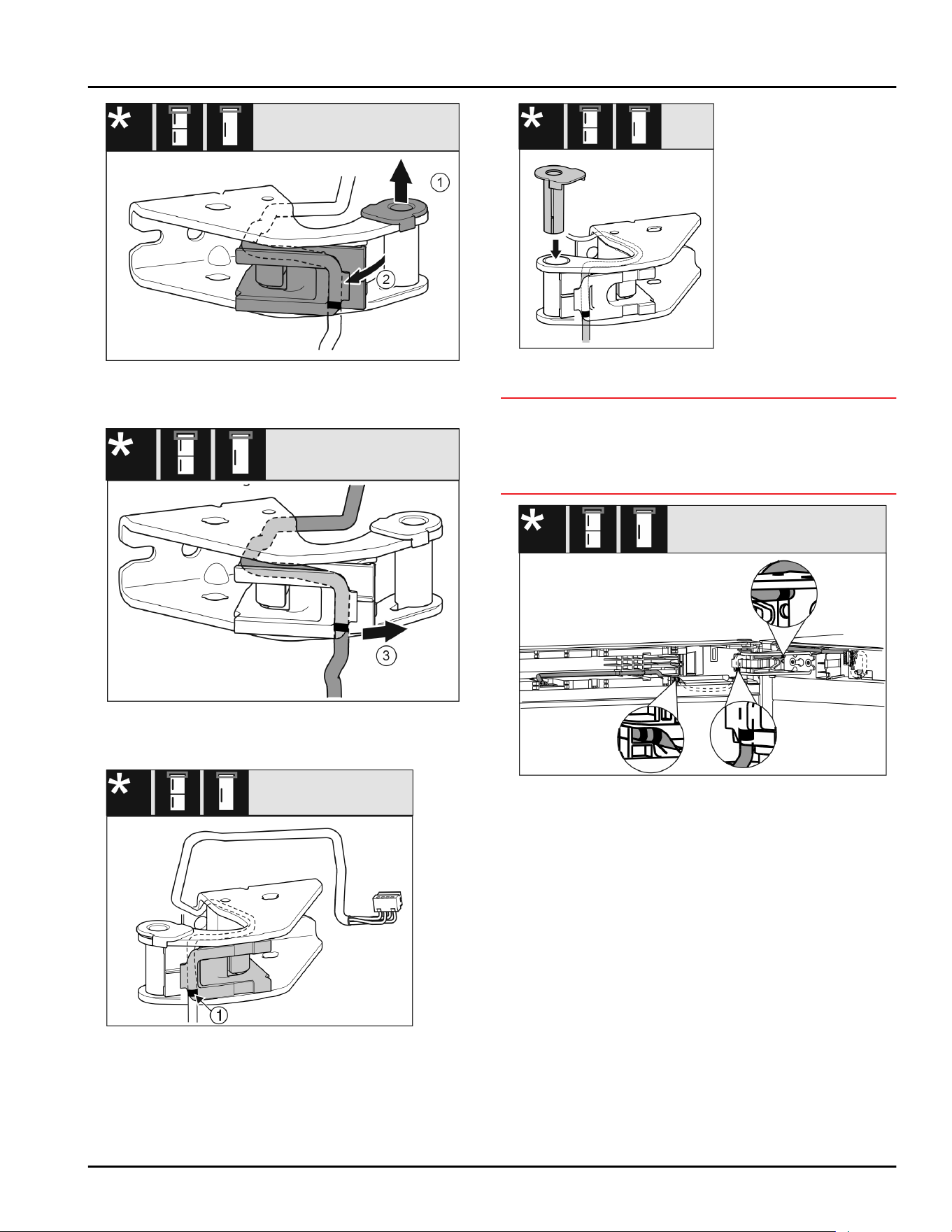
Fig. 24
u
Pull the bearing bush out of the guide. Fig. 24 (1)
u
Swing the cable holder out. Fig. 24 (2)
Fig. 25
u
Remove the cable with the cable holder from the
bearing bracket. Fig. 25 (3)
Fig. 26
u
Insert the cable mirror-inverted in the upper groove
of the cable holder.
w
The middle marking must be positioned on the edge
of the cable holder Fig. 26 (1).
u
Swing the cable holder in.
Fig. 27
u
Insert from the other side and latch into place.
NOTICE
Danger of crushing the cable
u
Pay attention to the markings when routing the
cable. The cable end with the double marking must
be routed into the door end piece.
Fig. 28
After making the change, the cable routing must look
as shown in the illustration.
Reversing the door
14 * Depending on model and options
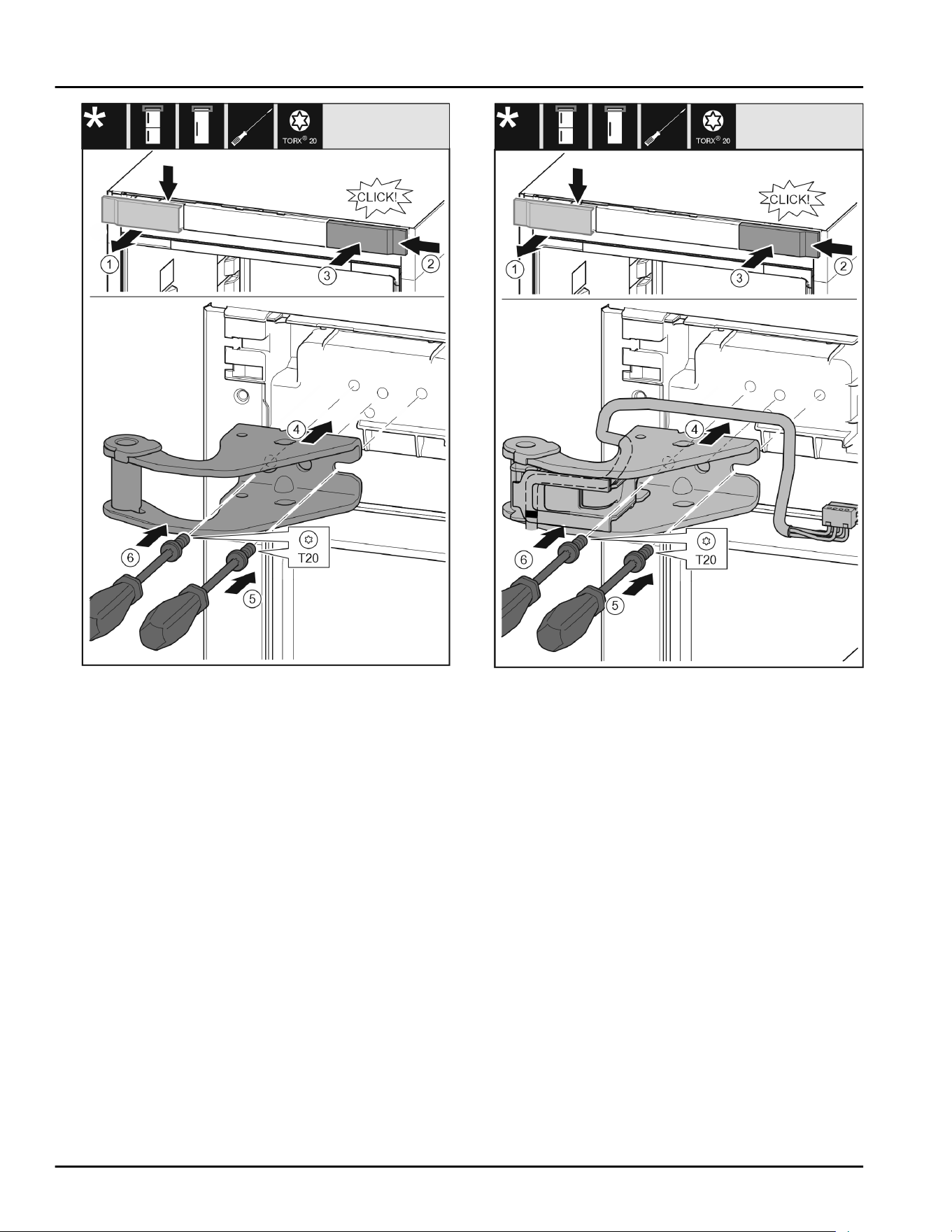
Fig. 29
u
Take off the cover to the front from above. Fig. 29 (1)
u
Rotate the cover 180° and clip onto the other side
from the right. Fig. 29 (2)
u
Latch the cover into place. Fig. 29 (3)
u
Position the upper bearing bracket. Fig. 29 (4)
u
Insert the screw with a T20 screwdriver and tighten
it. Fig. 29 (5)
u
Insert the screw with a T20 screwdriver and tighten
it. Fig. 29 (6)
Fig. 30
u
Take off the cover to the front from above. Fig. 30 (1)
u
Rotate the cover 180° and clip onto the other side
from the right. Fig. 30 (2)
u
Latch the cover into place. Fig. 30 (3)
u
Position the upper bearing bracket. Fig. 30 (4)
u
Insert the screw with a T20 screwdriver and tighten
it. Fig. 30 (5)
u
Insert the screw with a T20 screwdriver and tighten
it. Fig. 30 (6)
Reversing the door
* Depending on model and options 15
13.7 Moving the central bearing parts
to the other side
Fig. 31
u
Remove the washer. Fig. 31 (1)
u
Remove the screws with the T20 screwdriver.
Fig. 31 (2)
u
Remove the cover carefully. Fig. 31 (3)
u
Screw the bearing bracket and the film rotated 180°
firmly onto the other side. Fig. 31 (4)
u
Attach the cover rotated 180° onto the other side.
Fig. 31 (5)
u
Push the washer in from the front. Fig. 31 (6)
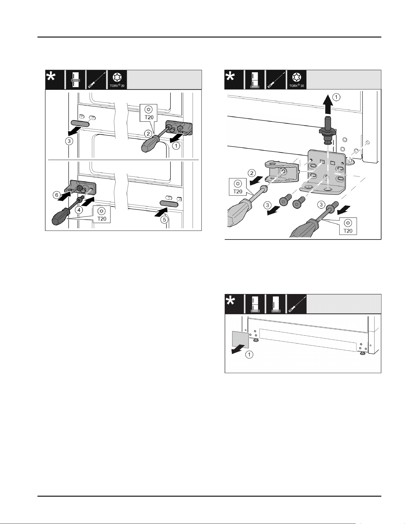
13.8 Moving the lower bearing parts
to the other side
Fig. 32
u
Lift the bearing pin completely upward and remove
it. Fig. 32 (1)
u
Remove the screw with the T20 screwdriver and take
off the soft close connection. Fig. 32 (2)
u
Remove the screws with the T20 screwdriver and
take off the bearing bracket. Fig. 32 (3)
Fig. 33
u
Take off the cover. Fig. 33 (1)
Reversing the door
16 * Depending on model and options
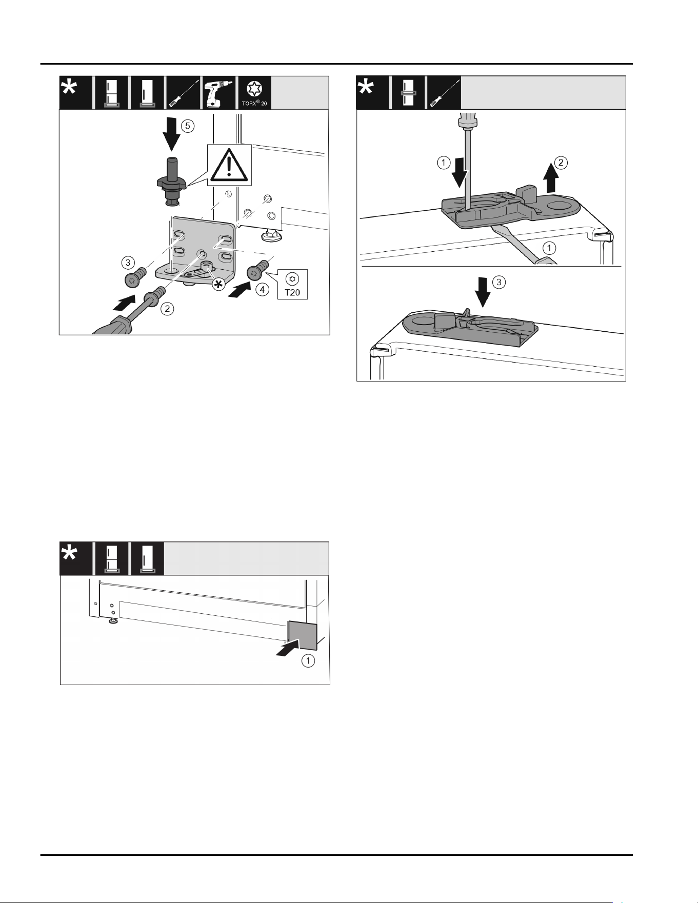
Fig. 34
u
Place the bearing bracket on the other side and
screw it in using the T20 screwdriver. Start with
screw 2 at the bottom in the middle. Fig. 34 (2)
u
Screw in screws 3 and 4. Fig. 34 (3,4)
u
Insert the bearing pin completely. Make sure that the
latching lug is pointing to the rear. Fig. 34 (5)
u
Place the bearing bracket on the other side and
screw it in using the T20 screwdriver. Start with
screw 2 at the bottom in the middle. (2)
u
Screw in screws 3 and 4. (3,4)
u
Rotate the soft stop connection 180°. Screw it on to
the other side of the bearing bracket with a T20
screwdriver. (5)
u
Insert the bearing pin completely. Make sure that the
latching lug is pointing to the rear. (6)
Fig. 35
u
Put back the cover on the other side. Fig. 35 (1)
13.9 Moving the door bearing parts to
the other side
Top door
Fig. 36
u
Underside of door faces upwards: Turn the door.
u
Pull out the guide bush: Press the lug with a slotted
screwdriver and, at the same time, insert the slotted
screwdriver under the guide bush. Fig. 36 (1, 2)
u
Slide the guide bush included in the scope of supply
to the other side of the housing. Fig. 36 (3)
u
Upper side of door faces upwards: Turn the door.
Reversing the door
* Depending on model and options 17
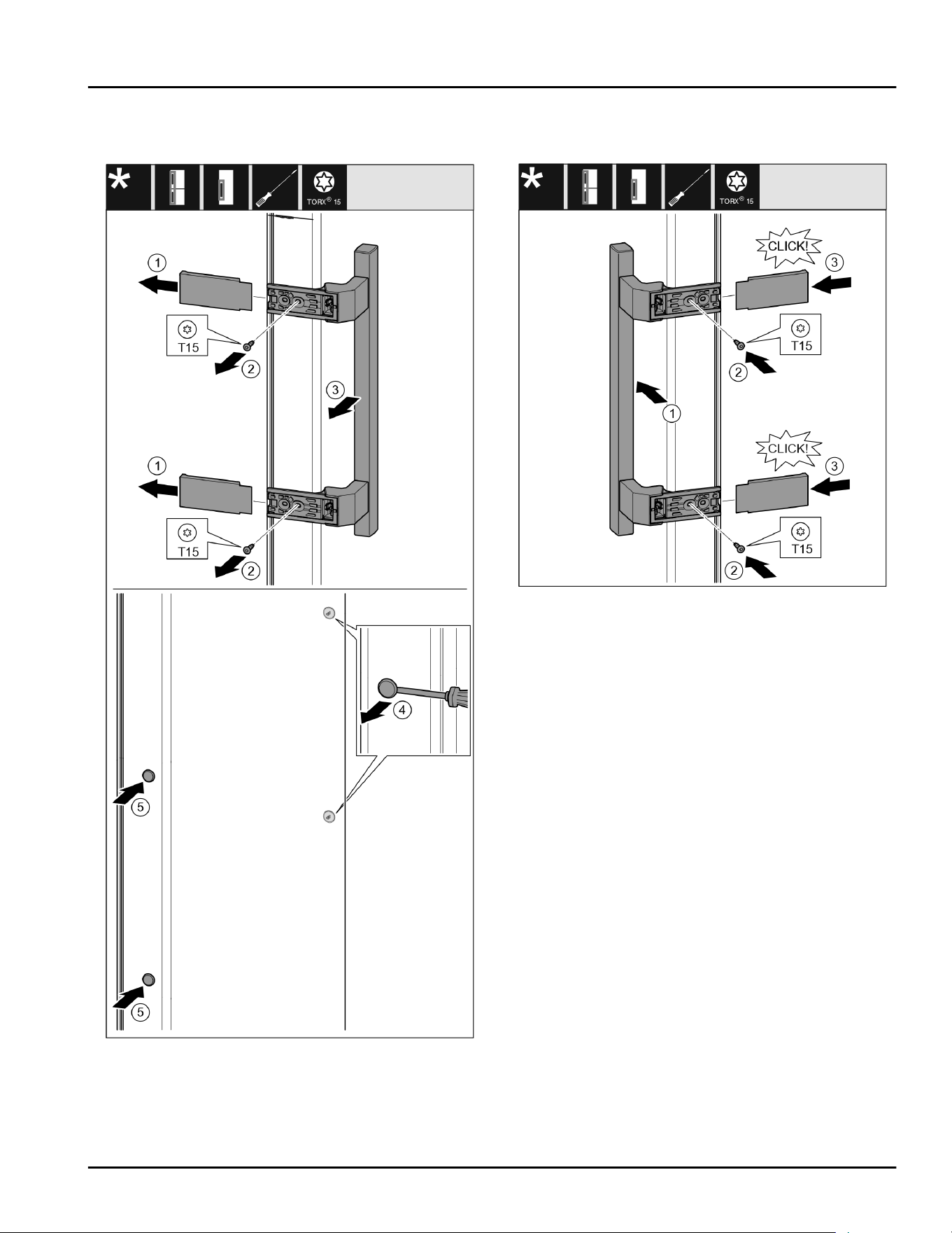
13.10 Moving the handles to the other
side*
Fig. 37
u
Pull off the cover. Fig. 37 (1)
u
Remove the screws with the T15 screwdriver.
Fig. 37 (2)
u
Remove the handle. Fig. 37 (3)
u
Carefully lift up the side plugs with a slotted screw‐
driver and pull them out. Fig. 37 (4)
u
Insert the plugs again on the other side. Fig. 37 (5)
Fig. 38
u
Position the handle on the opposite side. Fig. 38 (1)
w
The screw holes must be exactly above each other.
u
Tighten the screws using the T15 screwdriver.
Fig. 38 (2)
u
Position the covers on the side and push them on.
Fig. 38 (3)
w
Ensure that they latch into place correctly.
Reversing the door
18 * Depending on model and options
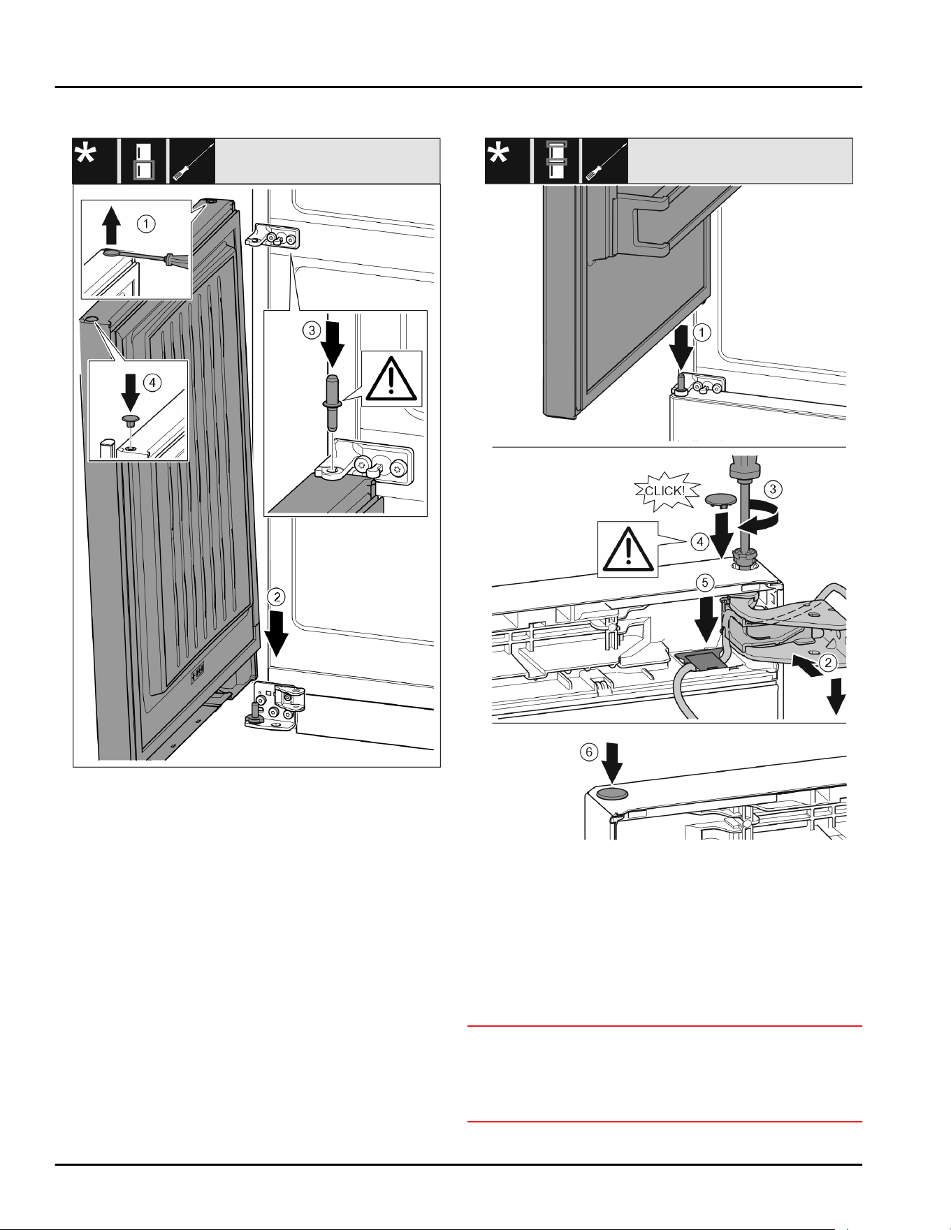
13.11 Fitting the bottom door
Fig. 39
u
Carefully lift up the plugs with a slotted screwdriver
and pull them out. Fig. 39 (1)
u
Position the door from above onto the lower bearing
pins. Fig. 39 (2)
u
Insert the center bearing pin through the center
bearing bracket into the bottom door. Make sure that
the latching lug is pointing to the rear. Fig. 39 (3)
u
Insert the plugs again on the other side of the door.
Fig. 39 (4)
13.12 Fitting the top door
Fig. 40
u
Place the upper door on the center bearing pins
Fig. 40 (1)
u
Align the top of the door with opening in the bearing
bracket. Fig. 40 (2)
u
Insert the bolt and tighten with a T15 screwdriver.
Fig. 40 (3)
u
Fit the protective cover to protect the door: Insert
the protective cover and check that it lies flush on
the door. If not, insert the bolt fully. Fig. 40 (4)
NOTICE
Cable crushing
u
The marking on the cable must be centered in the
holder. The lug with the longer opening must point
forwards.
Reversing the door
* Depending on model and options 19
u
Insert the cover and press it down until it latches
into place. Fig. 40 (5)
u
Insert the plugs. Fig. 40 (6)
13.13 Fitting the cable connection
Fig. 41
u
Take out the control panel carefully. Fig. 41 (1)
u
Turn the panel upward through 180°. Fig. 41 (2)
u
Engage the plug on the control panel. Fig. 41 (3)
u
Latch the control panel into the appliance again.
Fig. 41 (4)
u
Carefully position the gray cable in the guide above
the top bearing bracket. Fig. 41 (5)
Fig. 42
u
Insert the gray cable into the guide in the top door.
Fig. 42 (1)
u
Press the latching lug backward Fig. 42 (2)
u
Engage the plug. Fig. 42 (3)
u
Position the remaining cable length as a loop in the
guide, if required.
13.14 Aligning the doors
WARNING
Danger of injury due to door falling out!
If the bearing parts are not screwed on tightly enough,
the door may fall out. This can result in serious injuries.
In addition, the door may not close causing the appli‐
ance to cool improperly.
u
Screw the bearing brackets on tightly using
4 Nm (3 lb-ft) .
u
Check all screws and retighten them if necessary.
u
Align the doors flush with the appliance housing
using the two slots in the lower bearing bracket and
center bearing bracket if needed. To do this undo the
middle screw in the bottom bearing bracket with the
T20 tool supplied. Undo the remaining screws a little
with the T20 tool or with a T20 screwdriver and align
via the slots. Undo the screws in the middle bearing
bracket with the T20 tool and align the middle
bearing bracket via the slots.
u
Prop up the door: Screw out the adjustable foot on
the bearing bracket using the open-ended wrench
SW10 until it comes into contact with the floor, then
turn an additional 90°.
Reversing the door
20 * Depending on model and options
13.15 Fit the bottom soft stop mecha‐
nism
Fig. 43 *
u
Insert the adapter on the handle side in the recess.
Fig. 43 (1)*
u
Tighten the screws using the T15 screwdriver.
Fig. 43 (2)*
Fig. 44
u
Slide the soft stop mechanism on the bearing
bracket side at an angle into the recess as far as it
will go. Fig. 44 (1)
u
Slide the soft stop mechanism fully into the recess.
Fig. 44 (2)
w
The unit is positioned correctly when the rib on the
soft stop mechanism is in the guide.
u
Tighten the screw using a T15 screwdriver. Fig. 44 (3)
u
Push the cover over the hinge. Fig. 44 (4)
Fig. 45
The door is open 90°.
u
Turn the hinge in the mount. Fig. 45 (1)
u
Insert the bolt with a T15 screwdriver in the mount
and hinge. Make sure that the latching lug is sitting
correctly in the groove. Fig. 45 (2)
u
Push the bearing bracket cover along the hinge and
fit it on the mount. Fig. 45 (3)
u
Remove the locking device. Fig. 45 (4)
u
Position the panel on the handle side and swing it in.
Fig. 45 (5)
w
The panel is clicked into place.
u
Close the bottom door.
13.16 Fitting the top soft stop mecha‐
nism
Fig. 46 *
u
Insert the adapter on the handle side in the recess.
Fig. 46 (1)*
u
Tighten the screws using the T15 screwdriver.
Fig. 46 (2)*
Reversing the door
* Depending on model and options 21
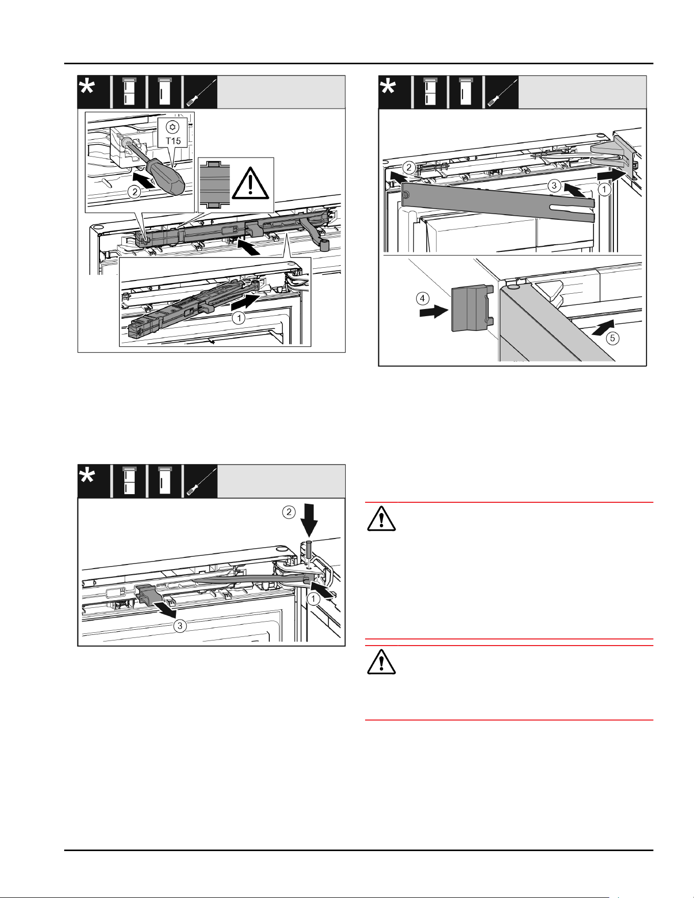
Fig. 47
u
Slide the soft stop mechanism on the bearing
bracket side at an angle into the recess as far as it
will go. Fig. 47 (1)
u
Slide the unit in fully.
w
The unit is positioned correctly when the rib on the
soft stop unit is in the guide on the housing.
u
Tighten the screw using a T15 screwdriver. Fig. 47 (2)
Fig. 48
The door is open 90°.
u
Turn the hinge in the bearing bracket. Fig. 48 (1)
u
Insert the bolt in the bearing bracket and hinge.
Make sure that the latching lug is sitting correctly in
the groove. Fig. 48 (2)
u
Remove the locking device. Fig. 48 (3)
Fig. 49
u
Position the bearing bracket cover and engage it. If
necessary push it apart carefully. Fig. 49 (1)
u
Place on the panel. Fig. 49 (2)
u
Swing in the panel and latch it into place. Fig. 49 (3)
u
Slide on the outer cover. Fig. 49 (4)
u
Close the upper door. Fig. 49 (5)
14 Water connection*
WARNING
Electricity and water!
Electric shock
u
Before connecting to the water hose: Disconnect the
appliance from the mains.
u
Before connecting to water lines: Shut off the water
supply.
u
The drinking water connection may only be carried
out by a qualified gas and water installer.
WARNING
Contaminated water!
Poisoning.
u
Connect to potable water supply only.
The appliance’s water connection and inlet solenoid
valve are suitable for a water pressure of up to 1 MPa
(10 bar).
Specifications for proper operation (flow rate, ice cube
size, noise level):
Water connection*
22 * Depending on model and options
Water pressure:
bar psi MPa
1.5 to 6.2 21.76 to 87.02 0.15 to 0.62
Water pressure if using the water filter:*
bar* psi* MPa*
2.8 to 6.2 40 to 90 0.28 to 0.62
If the pressure exceeds 0.62 MPa (6.2 bar): Connect a
pressure reducer.
Make sure that the following conditions are met:
q
The water pressure is correct.
q
Water is supplied to the appliance via a cold water
pipe that can withstand the operating pressure and
is connected to the drinking water supply.
q
A 1/4" OD copper pipe is used to connect the water
supply to the solenoid valve. This is not supplied
with the appliance.*
q
A connector between the R3/4 connection thread
and the 1/4" OD copper pipe is supplied with the
appliance.*
q
There is a filter with a seal in the copper pipe
connector. The filter with a seal is included in the
scope of delivery.*
q
There is a water valve between the copper pipe and
the domestic water connection in order to be able to
cut off the water supply if necessary.*
q
The water valve is located away from the back of the
appliance and is easily accessible so that the appli‐
ance can be pushed far back as possible and the
water valve can be quickly closed if required. The
correct clearances are maintained.
q
All equipment and devices used for the water supply
comply with the applicable regulations in the
country of use.
q
The back of the appliance is accessible so that you
can connect the appliance to the drinking water
supply.
q
Do not damage or kink the hose when setting up the
appliance.
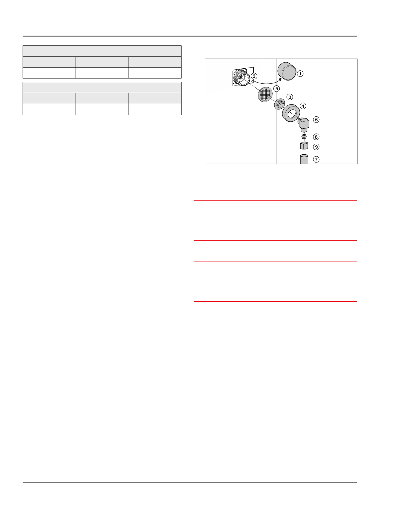
15 Connecting the water supply*
Fig. 50
Connect the coupler to the appliance
u
Remove cap Fig. 50 (1) from solenoid valve Fig. 50 (2).
u
Insert coupler Fig. 50 (3) into union nut Fig. 50 (4).
NOTICE
Improper installation of water filter Fig. 50 (5)!
Damage to the water filter.
u
Insert the filter with the recess pointing towards the
coupler.
u
Insert water filter Fig. 50 (5) with the recess pointing
down towards coupler Fig. 50 (3).
NOTICE
Overtightened union nut!
Damage to the thread.
u
Screw the union nut manually on to the thread until
it is tight and secure.
u
Attach union nut Fig. 50 (4) to solenoid valve Fig. 50 (2)
and tighten.
Water connection at 90°: Connect the water pipe to
the angle piece
u
Screw on angle piece Fig. 50 (6).
u
Connect water pipe Fig. 50 (7) (e.g. copper) to angle
piece Fig. 50 (6) using clamp ring Fig. 50 (8) and nut
Fig. 50 (9).
u
Attach water pipe Fig. 50 (7) to the housing if
possible, using the clip bracket.
Straight water connection: Connect the water pipe to
the coupler
u
Put angle piece Fig. 50 (6) to one side.
u
Connect water pipe Fig. 50 (7) (e.g. copper) to coupler
Fig. 50 (3) using clamp ring Fig. 50 (8) and nut
Fig. 50 (9).
u
Attach water pipe Fig. 50 (7) to the housing if
possible, using the clip bracket.
u
Connect the water pipe to the water valve.
Check the water system
u
Slowly open the water valve of the water supply.
u
Check the entire water system for leaks.
Vent the water system
Connecting the water supply*
* Depending on model and options 23
The system should be vented in the following situa‐
tions:*
- On initial setup
- When replacing the InfinitySpring water tank
Make sure that the following requirements are fulfilled:
- Appliance is fully connected
- Water tank is inserted (see Operating instructions,
Maintenance)
- Water filter is inserted (see Operating instructions,
Maintenance)
- Appliance is switched on
u
Open the appliance door
u
Take a glass and press it against the lower part of
the InfinitySpring dispenser.
w
The top section moves out and air or water is
dispensed into the glass.
u
Continue the process until a steady flow of water
pours into the glass.
w
There is no more air in the system.
u
Clean IceMaker (see Operating instructions, Mainte‐
nance).*
u
Clean InfinitySpring (see Operating instructions,
Maintenance).*
16 Water tank
Depending on your model, the InfinitySpring water tank
is behind the lowest drawer in the fridge or BioFresh
compartment
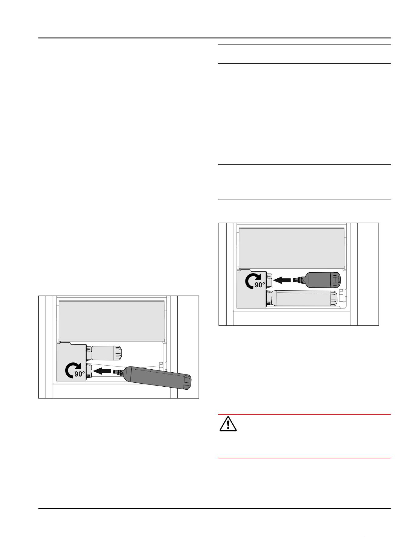
16.1 Inserting the water tank
Fig. 51
u
Remove the drawer.
u
Insert the water tank and turn approx. 90° to the
right until it engages.
u
Check that the water tank is sealed and no water
leaks out.
u
Insert the drawer.
u
Vent the water system (see Installation Instructions,
Water Connection)
Instead of the water filter, you can use an additional
water tank.
Note
The water tank is available as a spare part.
17 Water filter*
Depending on your model, the water filter is behind the
lowest drawer in the fridge or BioFresh compartment.
It absorbs deposits in the water and reduces the taste
of chlorine.
q
Replace the water filter at least every 6 months
under the specified usage conditions or if the flow
rate drops significantly.
q
The water filter contains carbon and can be
disposed of with the regular household waste.
Note
The water filter can be purchased from the Liebherr
Service Center. The address for your respective country
can be found on the back of the instructions.
17.1 Installing the water filter
Fig. 52
Make sure that the following conditions are met:
q
Water pressure is maintained (see Installation
Instructions, Water Connection).
u
Remove the drawer.
u
Insert the water filter and turn clockwise approx. 90°
until it engages.
u
Make sure the filter does not leak and no water is
coming out.
u
Insert the drawer.
CAUTION
New water filters may contain particulate matter.
u
Dispense 3 l (3.17 liq qt) of water through the Infini‐
tySpring and pour away.
w
The water filter is now ready for use.
Water tank
24 * Depending on model and options
18 Connecting the appliance
WARNING
Incorrect connection!
Risk of fire.
u
Do not use an extension cord.
u
Do not use a multipoint connector strip.
NOTICE
Incorrect connection!
Damage to the electronics.
u
Do not connect the appliance to a stand-alone
inverter, e.g. solar power systems and petrol genera‐
tors.
Note
Only use the mains cable supplied.
u
A longer mains cable can be ordered from Customer
Service.
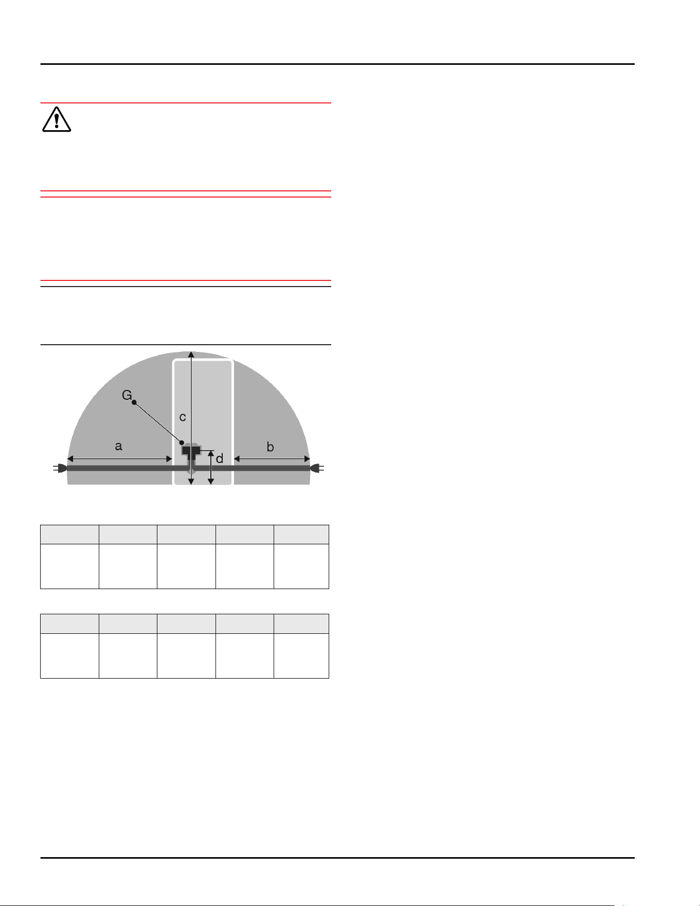
Fig. 53 *
For appliances with a width of 600 mm (23.62 in):*
a*
b* c* d* G*
~
1800 mm
(70.87 in)
~
1400 mm
(55.12 in)
~
2100 mm
(82.68 in)
~
200 mm
(7.87 in)
Appli‐
ance
plug
For appliances with a width of 750 mm (29.53 in):*
a*
b* c* d* G*
~
1725 mm
(67.91 in)
~
1325 mm
(52.17 in)
~
2100 mm
(82.68 in)
~
200 mm
(7.87 in)
Appli‐
ance
plug
Make sure that the following requirements are fulfilled:
- The type of current and voltage at the installation
site complies with the information on the serial tag .
- The socket is grounded and fused in accordance
with regulations.
- The tripping current for the fuse is between 10 and
16 A.
- The socket is easily accessible.
- The socket is not located behind the appliance but in
areas a or b Fig. 53 (a, b, c).
u
Check the electrical connection.
u
Insert the appliance plug Fig. 53 (G) on the rear side
of the appliance. Ensure that they latch into place
correctly.
u
Connect the mains plug to the power supply.
w
The Liebherr logo appears on the screen.
w
The display switches to the standby symbol.
Connecting the appliance
* Depending on model and options 25

home.liebherr.com/fridge-manuals
Combined fridge-freezer
Issue date: 20230131
Part number index: 7082929-00
For Service in the U.S.: Liebherr Service Center
Toll Free: 1-866-LIEBHER or 1-866-543-2437
Service-appliances.us@liebherr.com
PlusOne Solutions, Inc.
3501 Quadrangle Blvd, Suite 120
Orlando, FL 32817
For Service in Canada: Liebherr Service Center
Toll Free: 1-888-LIEBHER or 1-888-543-2437
www.euro-parts.ca
EURO-PARTS CANADA
39822 Belgrave Road, Belgrave, Ontario, N0G 1E0
Phone: (519) 357-3320 | Fax: (519) 357-1326