Installation Guide
Quality, Design and Innovation
home.liebherr.com/fridge-manuals
Contents
1 General safety instructions.......................... 2
2 Setup conditions............................................ 3
2.1 Space............................................................... 3
2.2 Setting up multiple appliances.......................... 3
2.3 Electrical connection........................................ 4
3 Appliance dimensions................................... 4
4 Recess dimensions....................................... 5
4.1 Internal dimensions.......................................... 5
5 Ventilation requirements............................... 5
6 Transporting the appliance........................... 5
7 Unpacking the appliance.............................. 5
8 Setting up the appliance............................... 5
8.1 After setup........................................................ 6
9 Disposal of packaging................................... 6
10 Explanatory symbols used........................... 6
11 **** freezer compartment door..................... 7
11.1 Moving the door hinge...................................... 7
12 Reversing the door........................................ 7
13 Water connection*......................................... 10
14 Connect the water supply*............................ 10
15 Fit the appliance into the recess.................. 11
16 Cabinet fronts................................................ 19
16.1 Dimensions...................................................... 19
16.2 Mounting the cabinet front(s)............................ 20
16.3 Setting the clearance to avoid collision............. 20
17 Water tank....................................................... 21
17.1 Inserting the water tank.................................... 21
18 Water filter...................................................... 21
18.1 Installing the water filter.................................... 21
19 Connecting the appliance............................. 21
The manufacturer is constantly working to improve all
types and models. Therefore, please be aware that we
reserve the right to make changes to the shape, equip-
ment and technology.
Symbol Explanation
Read instructions
Please read the information in these instruc-
tions carefully to understand all of the bene-
fits of your new appliance.
Symbol Explanation
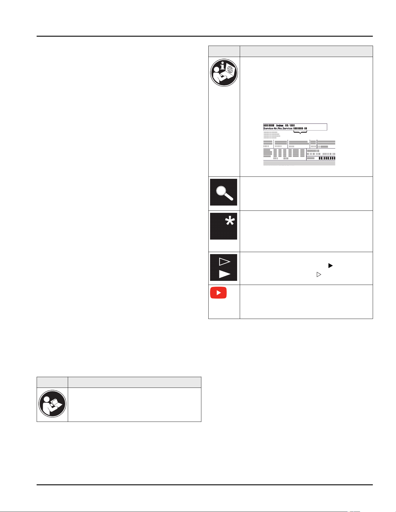
Full instructions on the internet
The detailed instructions are available via the
QR code on the front of these instructions, at
home.liebherr.com/fridge-manuals or by
entering the service number at
home.liebherr.com/fridge-manuals.
The service number can be found on the
serial tag
Fig. ()
.
Fig.
Example illustration
Check appliance
Check all parts for transport damage. If you
have any complaints, please contact your
agent or customer service.
Differences
These instructions apply to a range of
models, so there may be differences.
Sections that apply to certain models only are
indicated by an asterisk (*).
Instructions and results
Instructions are marked with a
.
Results are marked with a
.
Installation videos
Videos on installing appliances can be found
on the Liebherr Domestic Appliances
YouTube channel.
1 General safety instructions
-
Read and follow these instructions. They
contain safety advice which is important for
safe and problem-free installation and opera-
tion. Always read and follow the safety advice.
-
It is important that the guidelines and instruc-
tions in this manual are followed so that the
appliance is correctly installed and operates
properly Read and understand all information
in this manual before the appliance is installed
-
Risk of child entrapment:
Before you throw away your old refrigerator or
freezer:
Take off the doors. Leave the shelves in place
so that children may not easily climb inside.
-
Only install, connect and dispose of the appli-
ance in accordance with the instructions.
General safety instructions
2 * Depending on model and options
-
The socket must be easily accessible so that
the appliance can be disconnected from the
mains quickly in an emergency. It must not be
behind the back of the appliance.
-
IMPORTANT: The power plug must be easily
accessible so that the appliance can be
disconnected from the mains quickly in an
emergency. It must not be behind the back of
the appliance.
DANGER indicates a hazardous situation,
which if not avoided, will result in
death or serious injury.
WARNING indicates a hazardous situation,
which if not avoided, could result
in death or serious injury.
CAUTION indicates a hazardous situation,
which if not avoided, will result in
minor or moderate injury.
NOTICE indicates a hazardous situation,
which if not avoided, could result
in damage to property.
Note indicates useful advice and tips.
2 Setup conditions
WARNING
Risk of fire due to moisture!
If live parts or the power cord get wet, this can cause a
short circuit.
u
The appliance is designed for use in enclosed spaces.
Do not operate the appliance in open space or in damp
areas or where there is spray.
Normal use
-
Only set up and use the appliance in enclosed spaces.
-
Only use once installed.
2.1 Space
WARNING
Leaking refrigerant and oil!
Fire. The refrigerant contained within the appliance is
environmentally friendly, but flammable. The oil contained
within the appliance is flammable. Escaping refrigerant
and oil can ignite if they are of high enough concentration
and are exposed to an external heat source.
u
Do not damage the pipelines of the coolant circuit and
the compressor.
-
If the appliance is installed in a very damp environment
condensate water may form on the outside of the appli-
ance.
Always make sure the installation area is well venti-
lated. .
-
The more refrigerant is in the appliance, the larger the
room must be where the appliance is located. In the
case of a leak, a flammable gas-air mixture may be
created in a room that is too small. For every 0.28 oz
(8 g) of refrigerant, the installation space must be at
least 35.5 ft
3
(1 m
3
). Specifications regarding the refrig-
erant contained within the appliance can be found on
the rating plate inside the appliance.
2.1.1 Installation surface
-
The floor of the installation site must be horizontal and
level.
-
If the floor is not completely even, level the cabinet with
supports.
2.1.2 Installation position
-
Do not install the appliance in direct sunlight or next to
an oven, heater, or similar heat source.
-
Only install the appliance in solid cabinets.
2.2 Setting up multiple appliances
NOTICE
Risk of damage caused by water condensate!
u
Do not install this device directly beside another fridge/
freezer compartment.
NOTICE
Risk of damage caused by water condensate!
u
Do not stack the appliance directly on top of another.
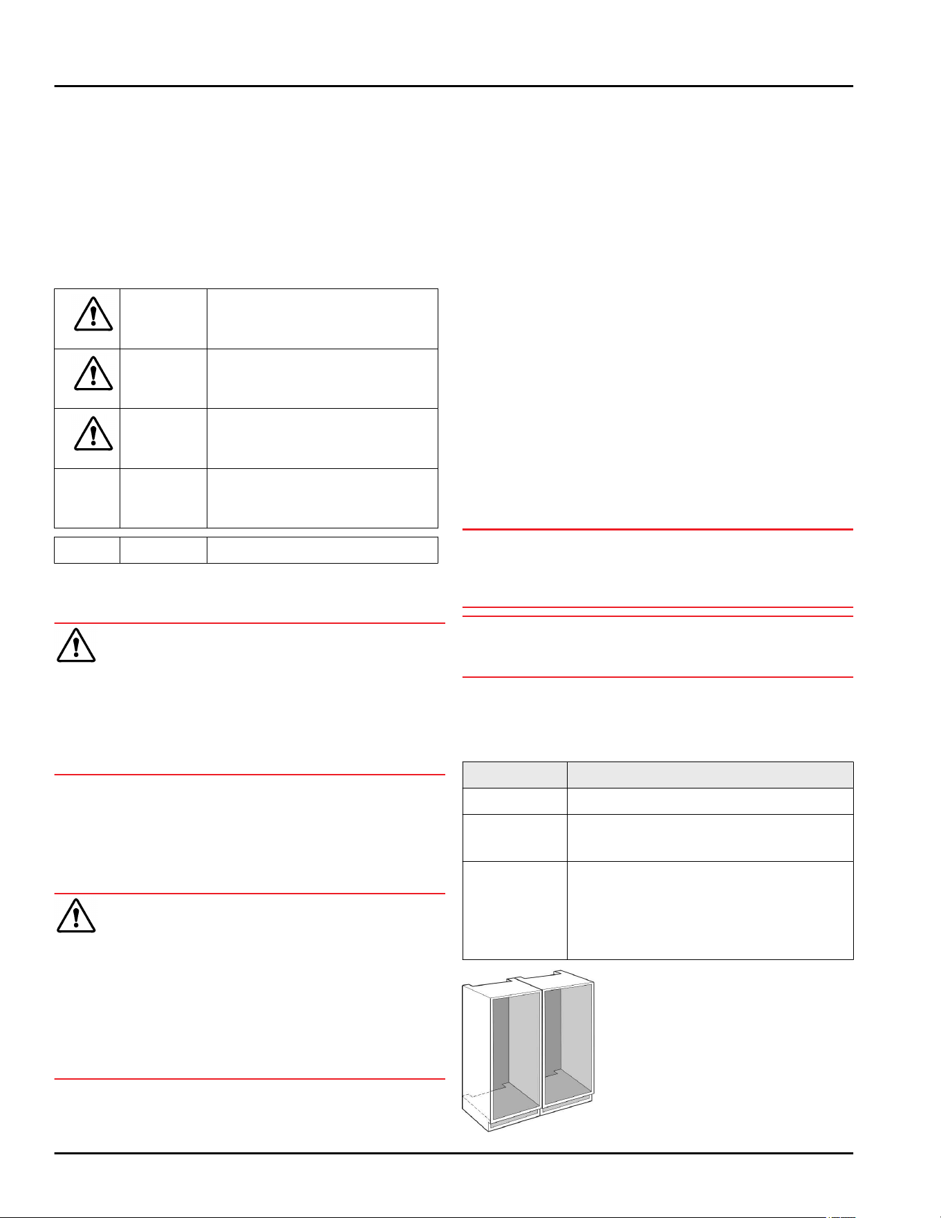
These appliances are designed for different types of
installation. Only combine appliances if the appliances are
designed for this. The following table shows the installa-
tion options by model:
Setup type Model
Single All models
Side-by-Side
(SBS)
Model that start with S....
See the SBS setup for positioning.
Stacked Models up to maximum recess height of
34-5/8 '' (880 mm) and with heated top
can be “stacked”.
Top appliance: to the max. recess height
of 5-1/2 '' (140 mm)
Fig. 1
Setup conditions
* Depending on model and options 3
Install each appliance into its own recess.
2.3 Electrical connection
WARNING
Improper use!
Fire. If a power cable/plug comes into contact with the
back of the appliance, the power cable/plug can be
damaged by appliance vibrations and this may result in a
short circuit.
u
Install the appliance so that it does not touch any plugs
or power cables.
u
Do not connect any appliances to sockets in the area of
the back of the appliance.
u
Multi-sockets/power distributors and other electronic
appliances (such as halogen transformers) may not be
placed and operated at the back of appliances.
3 Appliance dimensions
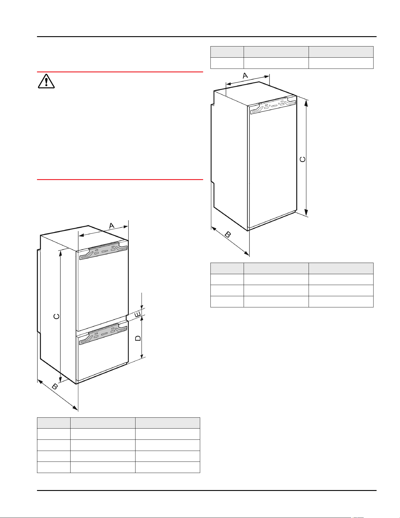
Fig. 2
in. mm
A 22 559
B 21 1/2 546
C 69 11/16 1770
D 27 3/8 695
in. mm
E 5/8 15
Fig. 3
in. mm
A 22 559
B 21 1/2 546
C 69 11/16 1770
Appliance dimensions
4 * Depending on model and options
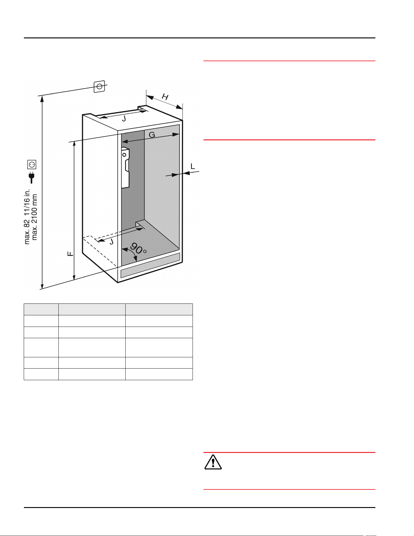
4 Recess dimensions
4.1 Internal dimensions
Fig. 4
in. mm
F 69 3/4 — 70 3/8 1772 — 1788
G 22 — 22 3/4 560 — 578
H min. 21 5/8, recom-
mended 22
min. 550, recom-
mended 560
J min. 19 11/16 min. 500
L max. 3/4 max. 19
The specified energy consumption was determined with a
kitchen unit depth of 22 in. (560 mm). The appliance will
work properly at a kitchen unit depth of 21 5/8 in.
(550 mm), but with a slightly higher energy consumption.
u
Check the wall thickness of adjacent cabinets: It must
be min. 5/8 in. (16 mm).
u
Only install the appliance in solid, fixed kitchen cabi-
nets. Ensure that the cabinets cannot tip over.
u
Align the cabinets with a spirit level and a try square. If
necessary, level them by putting something underneath
them.
u
Ensure that the floor and the side panels of the cabinet
are at right angles to each other.
5 Ventilation requirements
NOTICE
Covered vents!
Damage. Appliance can overheat, which can reduce the
service life of various parts of the appliance and lead to
functional impairments.
u
Always ensure good ventilation.
u
Always keep vents or ventilation grills in the appliance
housing and in the kitchen structure (built-in appliance)
unobstructed.
u
Never block air vents of the fan.
Comply with the ventilation gaps:
-
The depth of the ventilation shaft on the back wall of the
cabinet must be at least 1 1/2 in. (38 mm).
-
At least 31 in.
2
(200 cm
2
) is required for the ventilation
cross-sections below the unit at its base and above the
unit in the surrounding cabinet.
-
Basically, the larger the ventilation cross-section, the
more efficiently the appliance will run.
Sufficient ventilation is required for the appliance to
operate correctly. The pre-fitted vents ensure an effective
air-flow cross-section on the appliance of 31 in.
2
(200 cm
2
). If you replace the vents with a cover panel, it
must have at least an equal or larger air-flow cross-section
than the manufacturer’s vent.
6 Transporting the appliance
u
Transport the appliance in its packaging.
u
Transport the appliance upright.
u
Do not move the appliance on your own.
7 Unpacking the appliance
If the appliance is damaged check with the supplier imme-
diately before connecting it.
u
Check the appliance and packaging for damage during
transport. If you suspect any damage, please contact
your supplier immediately.
u
Remove all materials that could prevent it from being
installed properly or prevent proper ventilation from the
back or the side panels of the appliance.
u
Remove all protective films from the appliance. Do not
use sharp or pointed objects for this.
u
Remove the mains cable from the back of the appli-
ance. Also remove the cable holder, otherwise there
will be vibration noise!
8 Setting up the appliance
CAUTION
Risk of personal injury!
u
Have two people move this appliance into place.
Recess dimensions
* Depending on model and options 5
WARNING
Unstable appliance!
Risk of injury and damage. The appliance can tip over.
u
Secure the appliance according to the operating
instructions.
WARNING
Danger of fire and damage!
u
Do not place devices that give off heat, e.g. micro-
waves, toasters, etc. on the appliance.
If possible, have a professional install the appliance in
your kitchen cabinet unit.
Do not install the appliance without assistance.
8.1 After setup
u
Remove all transport packaging.
Fig. 5
*
u
Remove the red transport
safety device.
*
u
Clean the appliance (see User Guide, Cleaning the
appliance).
u
Write down the type (model, number), appliance name,
appliance/serial number, date of purchase and dealer
address in the designated fields (see User Guide,
About the appliance).
9 Disposal of packaging
WARNING
Danger of suffocation from packaging materials and films!
u
Do not allow children to play with packaging materials.
The packaging is made from recyclable materials:
-
Corrugated card/cardboard
-
Parts made of foamed polystyrene
-
Films and bags from polyethylene
-
Packing bands from polypropylene
-
Wood frame nailed together with a polyethylene
window*
u
Take the packaging material to an official collection
point.
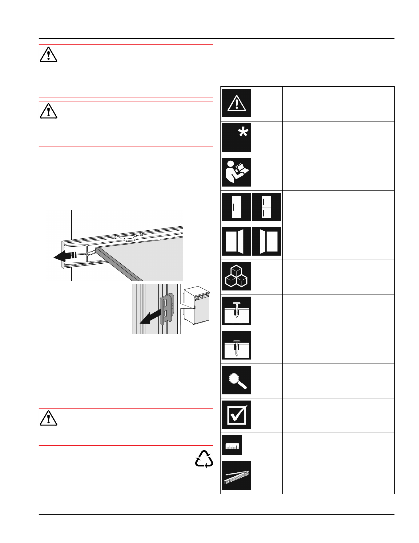
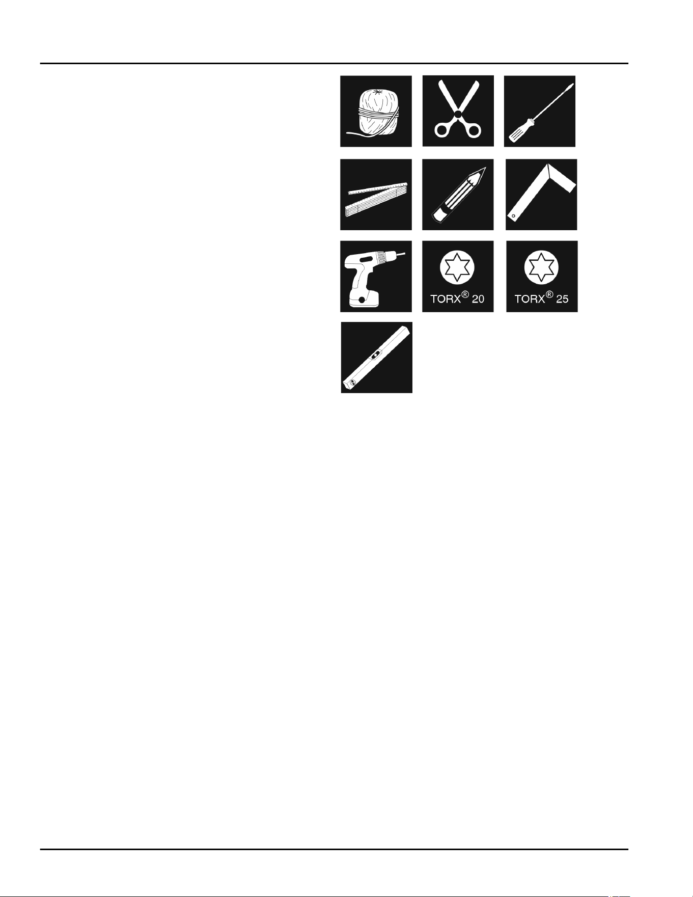
10 Explanatory symbols used
There is the risk of injury when
doing this! Obey the safety instruc-
tions!
These instructions apply to several
models. Only perform this step if it
applies to your appliance.
To install, please follow the detailed
description in the Guide.
This section applies either to a
single-door appliance or a double-
door appliance.
Choose one of the options: Appli-
ance with right-hinged door or
appliance with left-hinged door.
Installation step necessary with
IceMaker and/or InfinitySpring.
Loosen or tighten screws slightly.
Tighten the screws fully.
Check to see if the next step
applies for your model.
Check the components are in
correctly.
Measure the specified measure-
ment and adjust if necessary.
Installation tool: Meter stick
Disposal of packaging
6 * Depending on model and options
Tool for assembly: Cordless screw-
driver and attachments
Tool for assembly: Spirit level
Tool for assembly: Size 7 and size
10 spanner
Two people are required for this
step.
This step takes place at the
selected location of the appliance.
Aid for assembly: String
Aid for assembly: Square
Aid for assembly: Screwdriver
Aid for assembly: Scissors
Aid for assembly: Non-permanent
marker pen
Accessory kit: Remove compo-
nents
Dispose of components that are no
longer needed.
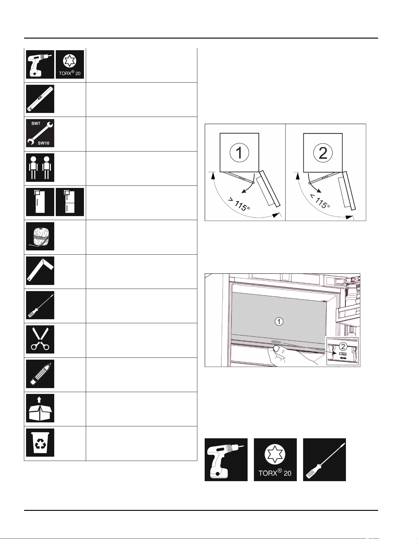
11 **** freezer compartment
door
The **** freezer compartment door can be easily moved
whenever changing the door hinge. If the door of the
refrigerator can be opened more than 115° (1), the freezer
compartment can also be opened without changing the
hinge. If the opening angle (2) of the appliance door is
less than this, the door hinge must be repositioned.
Fig. 6
11.1 Moving the door hinge
The slider for moving the door hinge is located on the
back of the **** freezer compartment door at the bottom.
Fig. 7
u
Close the **** freezer compartment door (1).
u
Grab the **** freezer compartment door from below.
u
Slide the slider (2) either to the right or to the left.
12 Reversing the door
Tool
Fig. 8
**** freezer compartment door
* Depending on model and options 7
NOTICE
Live parts
Damage to electrical parts
u
Before changing the door hinge, disconnect the plug at
the mains.
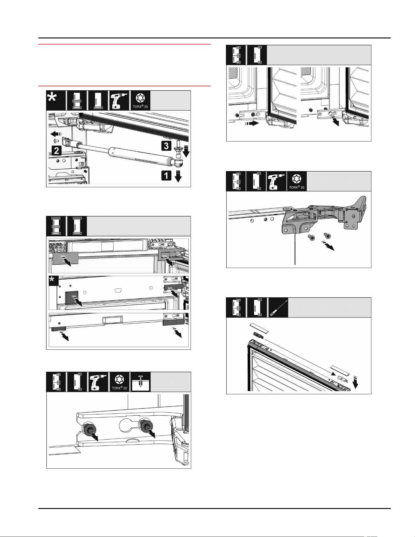
Fig. 9
u
Removing the soft stop damper: Remove the soft stop
damper from the ball stud (1). Unscrew the retainer (2).
Remove the ball stud with a screwdriver (3).
Fig. 10
u
Remove covers.
Fig. 11
u
Loosen the screws on all hinges but do not remove
them.
Fig. 12
u
Remove the door: Push the door forward and then out,
unhook it and put it to one side.
Fig. 13
u
Unscrew all hinges and set aside together with the
screws.
Fig. 14
u
Loosen and shift the bracket at the top and bottom of
the door. The bracket must be shifted so you can screw
on the hinges.
Reversing the door
8 * Depending on model and options
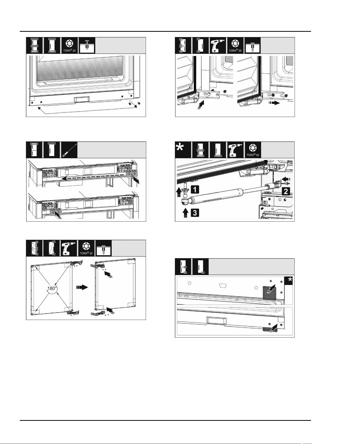
Fig. 15
u
Shift the screws to fasten the hinge. Do not screw
tightly after shifting – you need to hang the hinges later.
Fig. 16
u
Swap the fixing bracket to the opposite side.
Fig. 17
u
Turn all hinges 180° to the opposite side and screw
firmly.
Fig. 18
u
Refitting the door: Hang the door with its hinges and
tighten the screws.
Fig. 19
u
Refit the closing dampers: Screw in the ball studs (1),
tighten the bracket (2), and hang the closing dampers
in the ball studs.
u
Check all screws and retighten if necessary.
Fig. 20
u
Reassemble the bottom and center cover. Only replace
the remaining covers after installing the appliance back
into the cabinet.
Reversing the door
* Depending on model and options 9
13 Water connection*
WARNING
Electricity and water!
Electric shock
u
Before connecting to the water hose: Disconnect the
appliance from the mains.
u
Before connecting to water lines: Shut off the water
supply.
u
The drinking water connection may only be carried out
by a qualified gas and water installer.
WARNING
Contaminated water!
Poisoning.
u
Connect to potable water supply only.
The appliance’s water connection and inlet solenoid valve
are suitable for a water pressure of up to 1 MPa (10 bar).
Specifications for proper operation (flow rate, ice cube
size, noise level):
Water pressure
bar psi MPa
1.5 to 6.2 21.76 to 87.02 0.15 to 0.62
Water pressure if using the water filter:
bar psi MPa
2.8 to 6.2 40 to 90 0.28 to 0.62
If the pressure exceeds 0.62 MPa (6.2 bar): Activate the
pressure reducer first.
Ensure that the following conditions are met:
q
Water pressure is maintained.
q
Water is supplied to the appliance via a cold water pipe
that can withstand the operating pressure and is
connected to the drinking water supply.
q
Use a 1/4” OD copper pipe to connect the water
supply to the solenoid valve. This is not supplied
with the appliance.
q
A connector between the R3/4 connection thread and
the 1/4" OD copper cable is supplied with the appli-
ance.
q
There is a filter with a seal in the copper pipe
connector. The filter with a seal is included in the scope
of delivery.
q
There is a stopcock between the copper pipe and the
domestic water connection in order to be able to cut off
the water supply if necessary.
q
The stopcock is located outside the back of the appli-
ance and is easily accessible so that the appliance can
be far back as possible and the valve can be turned on
quickly, if necessary. Distance dimensions are adhered
to.
q
All equipment and devices used for the water supply
comply with the applicable regulations of the country of
use.
q
The rear of appliance is accessible so that you can
connect the appliance to the drinking water supply.
q
Do not damage or buckle the hose when setting it up.
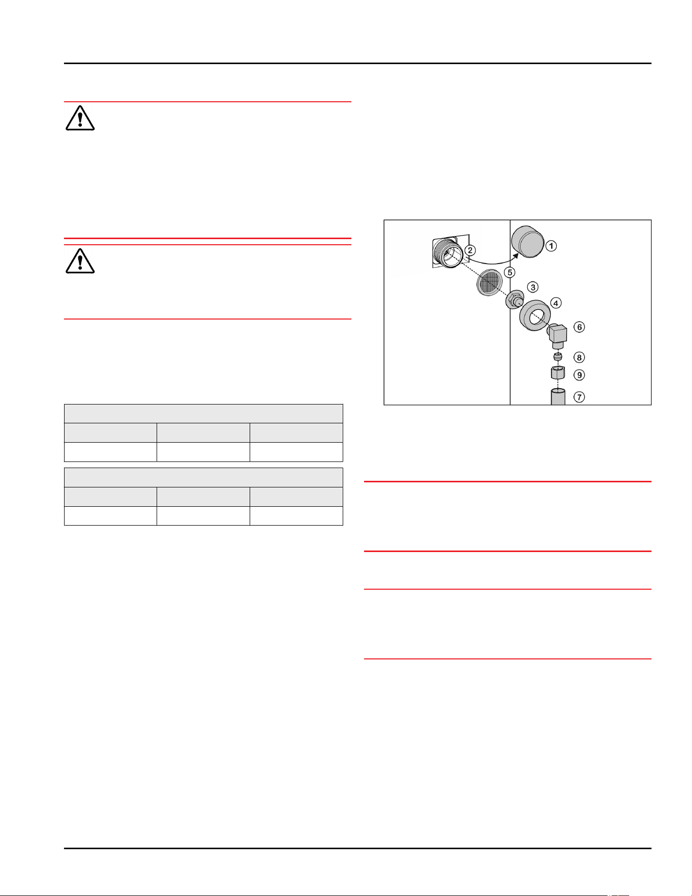
14 Connect the water supply*
Fig. 21
Connect the coupler to the appliance
u
Remove the cap
Fig. 21 (1)
from the solenoid valve
Fig. 21 (2)
.
u
Insert the coupler
Fig. 21 (3)
into the union nut
Fig. 21 (4)
.
NOTICE
Improper installation of the water filter
Fig. 21 (5)
!
Damage to the water filter.
u
Insert the filter with the recess pointing towards the
coupler.
u
Insert the water filter
Fig. 21 (5)
with the recess pointing
down towards the coupler
Fig. 21 (3)
.
NOTICE
Overtightened union nut!
Damage to the thread.
u
Screw the union nut manually on to the thread until it is
tight and secure.
u
Attach the union nut
Fig. 21 (4)
to the solenoid valve
Fig. 21 (2)
and tighten.
Water connection at 90°: Connect the water hose to
the angle piece
u
Screw on the angle piece
Fig. 21 (6)
.
u
Connect the water hose
Fig. 21 (7)
(e.g. copper) to the
angle piece
Fig. 21 (6)
using the clamp ring
Fig. 21 (8)
and nut
Fig. 21 (9)
.
u
Attach the water hose
Fig. 21 (7)
to the housing if
possible, using the clip bracket.
Straight water connection: Connect the water hose
to the connecting piece
u
Put the angle piece
Fig. 21 (6)
to the side.
Water connection*
10 * Depending on model and options
u
Connect the water hose
Fig. 21 (7)
(e.g. copper) to the
connecting piece
Fig. 21 (3)
using the clamp ring
Fig. 21 (8)
and nut
Fig. 21 (9)
.
u
Attach the water hose
Fig. 21 (7)
to the housing if
possible, using the clip bracket.
u
Connect the water hose to the stopcock.
Checking the water system
u
Slowly open the mains stopcock of the water supply.
Before installing in the recess:
u
Check the entire water system for leaks.
Venting the water system
The system should be vented in the following situations:
- Initial commissioning
- Changing the InfinitySpring water tank
Make sure that the following requirements are fulfilled
- Appliance is fully installed and connected
- Water tank is inserted (see User Guide, Maintenance)
- Water filter is inserted (see User Guide, Maintenance)
- Appliance is on
u
Open the appliance door
u
Take a glass and press it against the lower part of the
InfinitySpring dispenser.
w
The top section moves out and air or water is
dispensed into the glass.
u
Continue the process until a steady flow of water pours
into the glass.
w
There is no more air in the system.
u
Clean the IceMaker (see User Guide, Maintenance).
u
Clean the InfinitySpring (see User Guide, Mainte-
nance).
15 Fit the appliance into the
recess
Tool
Fig. 22
Supplied installation parts
Fit the appliance into the recess
* Depending on model and options 11
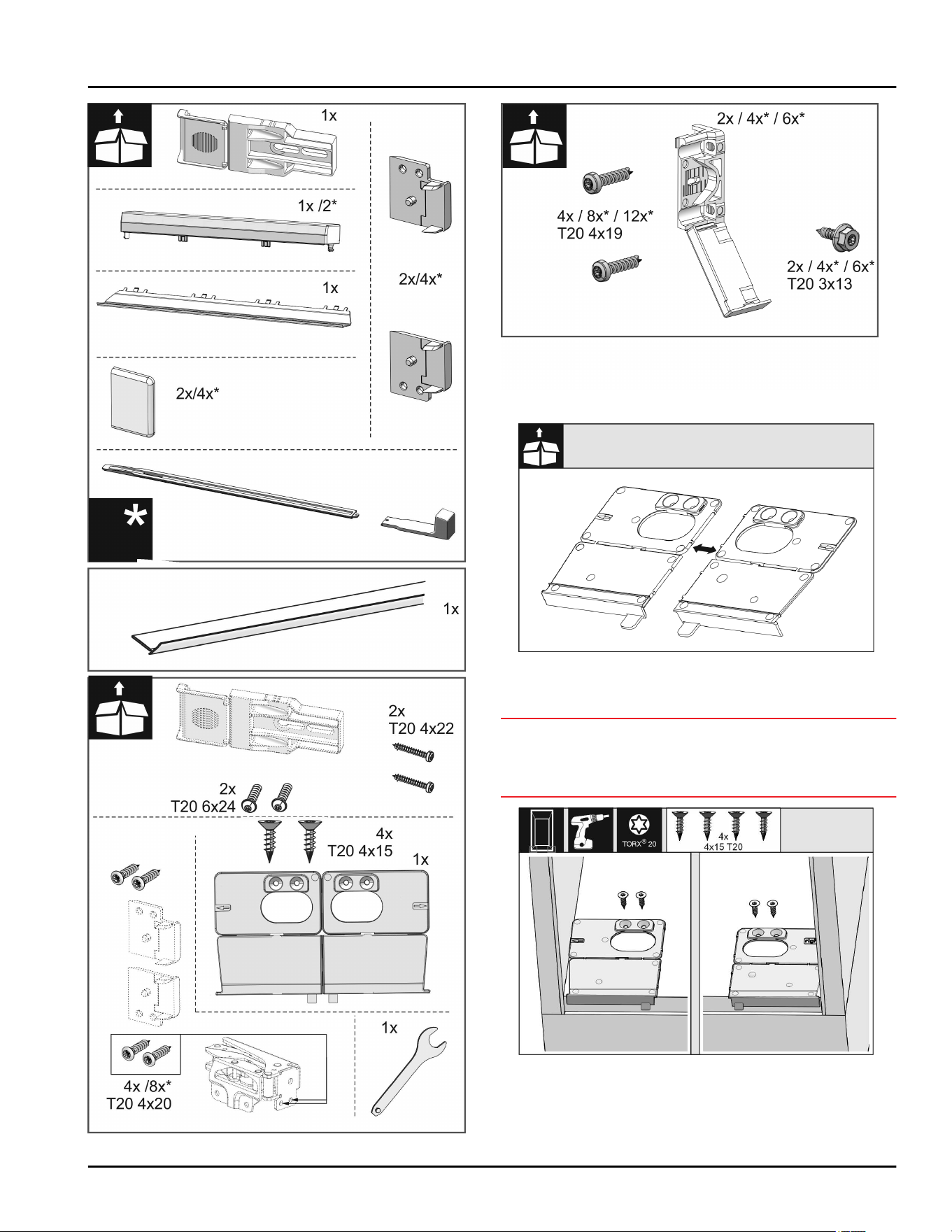
Fig. 23
Fig. 24
Fig. 25
u
Separate the floor mounting bracket
Fig. 25 ()
at the
perforation.
NOTICE
Correct installation depth of the appliance.
u
Using the mounting bracket ensures the correct instal-
lation depth of the appliance.
Fig. 26
u
Screw the mounting brackets on the left and right of the
recess floor, flush to the side wall.
Fit the appliance into the recess
12 * Depending on model and options
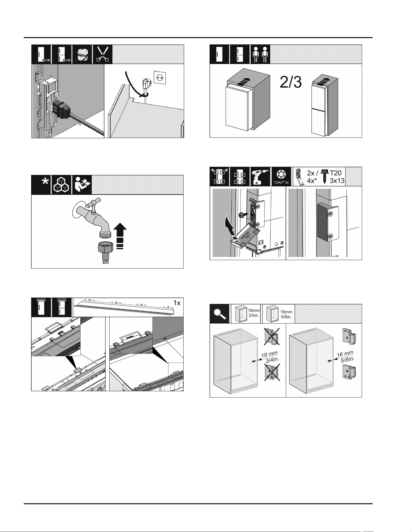
Fig. 27
u
Remove the power cable from the package and plug it
into the back of the appliance. Use a cable lug to lay
the power plug cord to the accessible socket.
Fig. 28
u
If necessary, install the water connection at this point,
following the instructions in the User Guide.
Fig. 29
u
Insert the adapter panel on the top of the appliance.
The panel can be moved to both sides.
Fig. 30
u
Slide the appliance 2/3 of the way into the cabinet
recess.
Fig. 31
u
Assemble the mounting bracket. Attach the mounting
brackets to align with the cabinet door handles. If the
door is large use four mounting brackets in total. After
assembly, fold the covers onto the bracket.
Fig. 32
u
Check whether the unit side wall is 5/8 in. (16 mm) or
3/4 in. (19 mm) thick.
Fit the appliance into the recess
* Depending on model and options 13
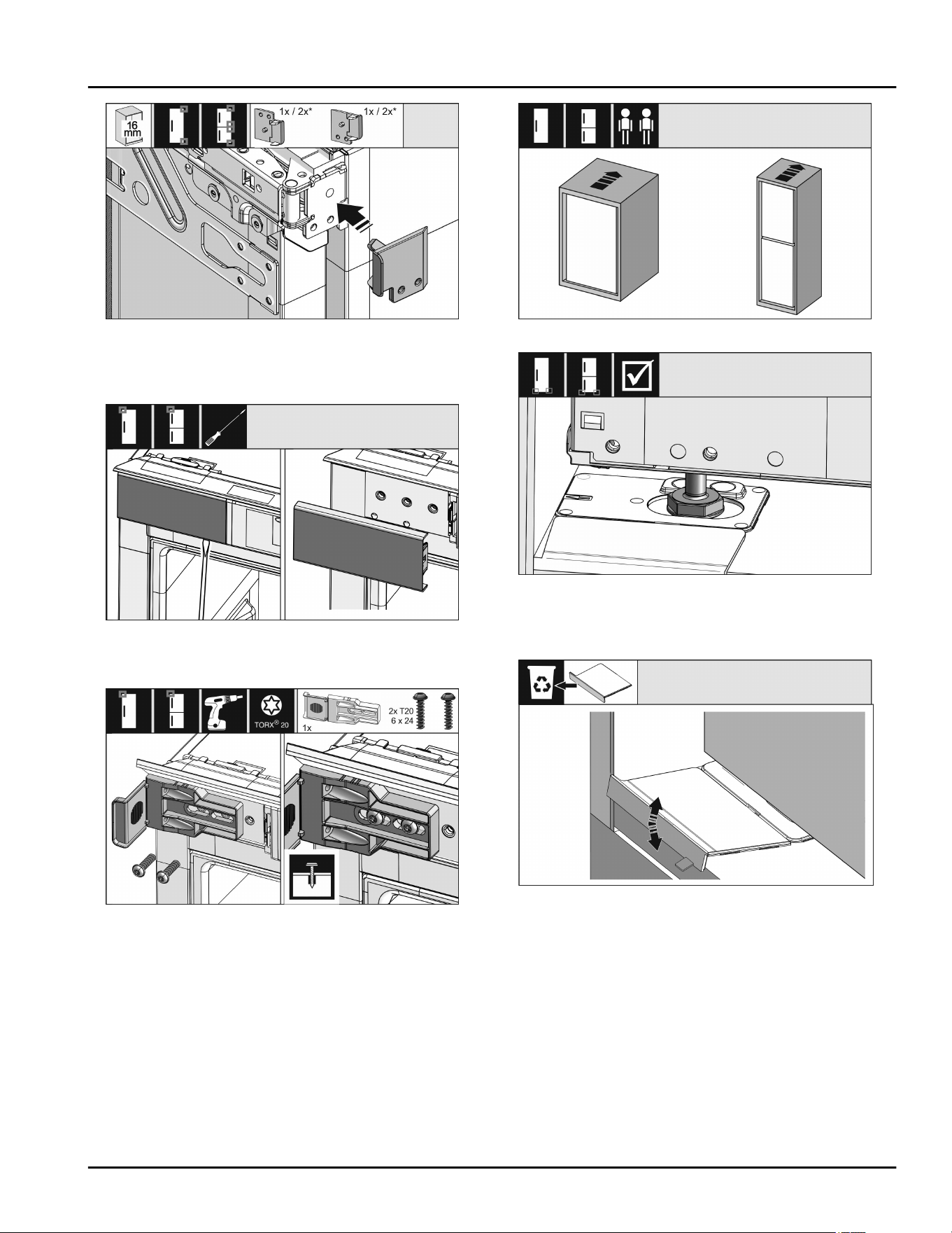
Fig. 33
u
For unit walls which are 5/8 in. (16 mm) thick: Clip a
spacer on all hinges. No spacer is required if the unit
walls are 3/4 in. (19 mm) thick.
Fig. 34
u
Use a screwdriver to loosen the cover at the top left and
then remove it.
Fig. 35
u
Loosely screw on the mounting bracket. The bracket
should still be easy to move.
Fig. 36
Fig. 37
u
Now insert the appliance all the way into the unit
recess. The adjustable feet must rest in the recesses in
the brackets on both sides.
Fig. 38
u
Remove the floor mounting bracket stopper. Loosen the
stopper by moving it and, if necessary, pull it off with the
help of pliers.
Fit the appliance into the recess
14 * Depending on model and options
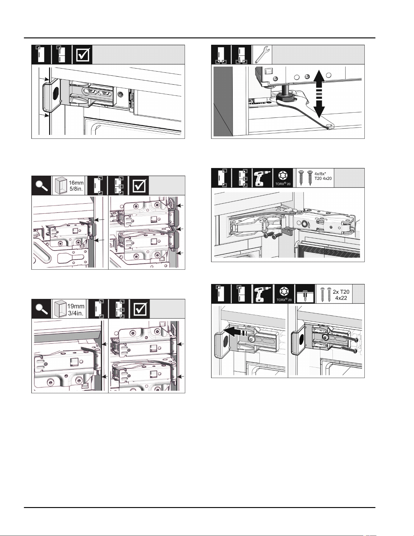
Fig. 39
u
Check that the appliance is flush in the cabinet recess.
The mounting bracket must be attached to the side wall
of the cabinet recess.
Fig. 40
u
For unit side walls which are 5/8 in. (16 mm) thick, the
spacers fit against the unit recess on the hinge side.
Fig. 41
u
For unit side walls which are 3/4 in. (19 mm) thick, the
front sides of the hinges are positioned flush against
the front of the unit side wall.
Fig. 42
u
If necessary, level the appliance using the adjusting
feet.
Fig. 43
u
Screw on the appliance on the hinge side.
Fig. 44
u
Move the bracket so it sits flush on the side wall of the
cabinet recess. Tighten all the screws firmly.
Fit the appliance into the recess
* Depending on model and options 15
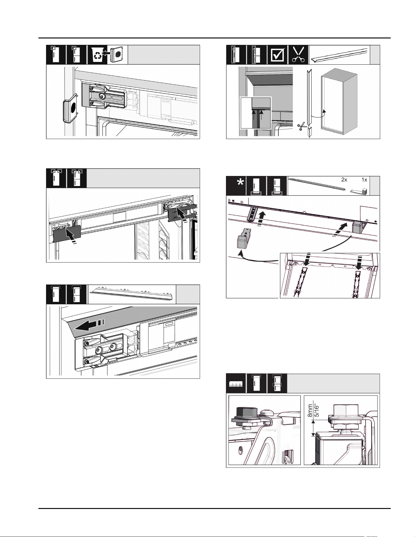
Fig. 45
u
Remove the stop from the bracket on the handle side
and dispose of it.
Fig. 46
u
Place the cover.
Fig. 47
u
Move the cover panel so it sits flush on the side of the
cabinet wall.
Fig. 48
u
The trim is magnetic. Place the trim below the top cover
and press. If necessary, shorten the trim to the required
length with a sharp pair of scissors.
Fig. 49
The height adjustment is only supplied as standard for
recess heights of .55 1/8 in. (140 cm) and above. It is
used for sound optimization. Both parts of the height
adjustment are included in the accessory kit.
u
To stabilize the appliance at the back underneath: Fit
the handle onto the rail of the height adjustment and
push the rail into the appliance base. Remove the
handle and do the same with the second rail.
Fig. 50
u
Close the door and check the preset of 5/16 in. (8 mm)
from the upper edge of the appliance door to the cross-
piece support
Fit the appliance into the recess
16 * Depending on model and options
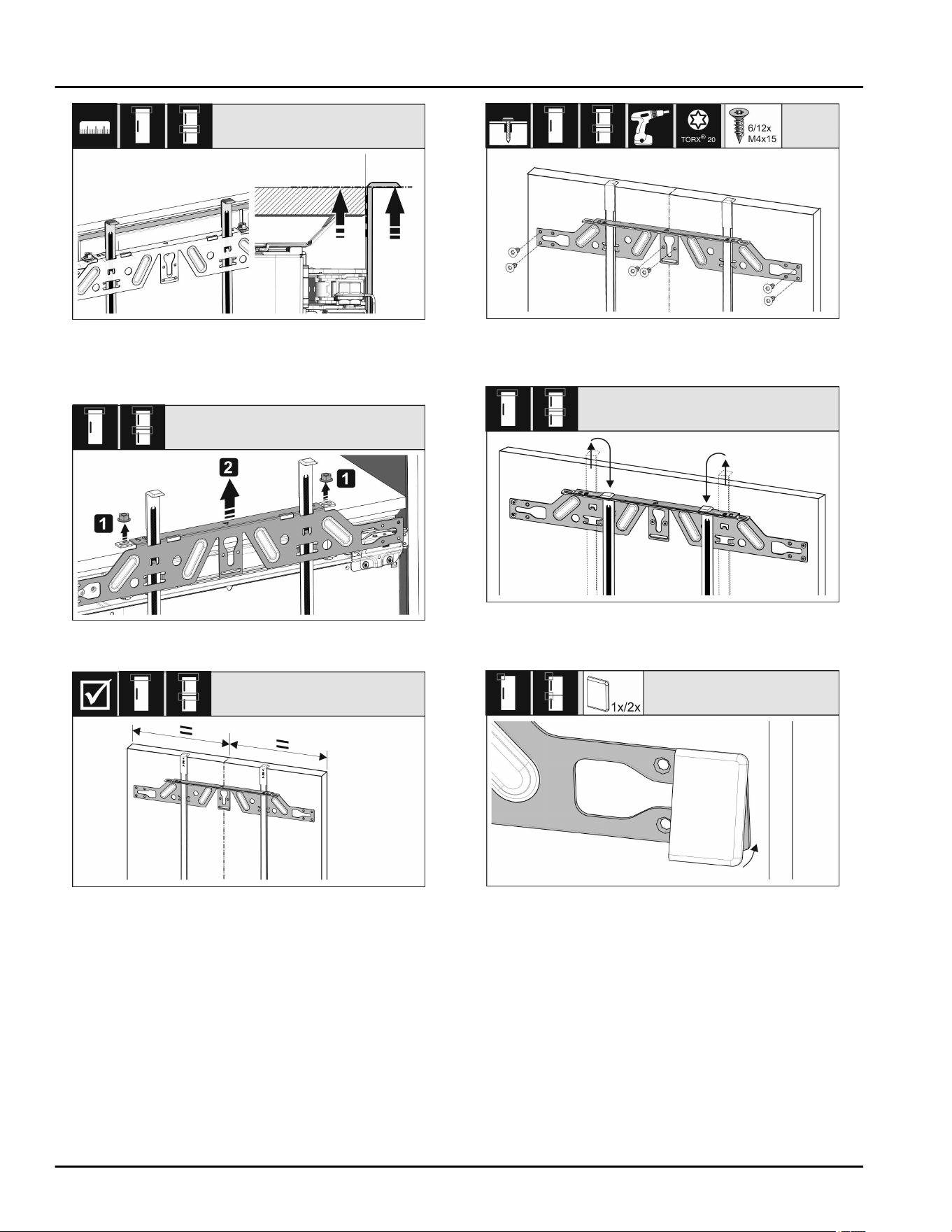
Fig. 51
u
Push up mounting aids to the height of the cabinet
door. Bottom stop edge of the fitting aid = top edge of
the door to be fitted.
Fig. 52
u
Undo the counter nuts and remove the crosspiece.
Fig. 53
u
Center-align the crosspiece on the inside of the cabinet
door.
Fig. 54
u
Fix the crosspiece using at least 6 screws for chipboard
doors and at least 4 screws for panel doors.
Fig. 55
u
Remove the fitting aids, turn round and insert into the
adjacent opening.
Fig. 56
u
Clip the cover on the crosspiece on the handle side.
Fit the appliance into the recess
* Depending on model and options 17
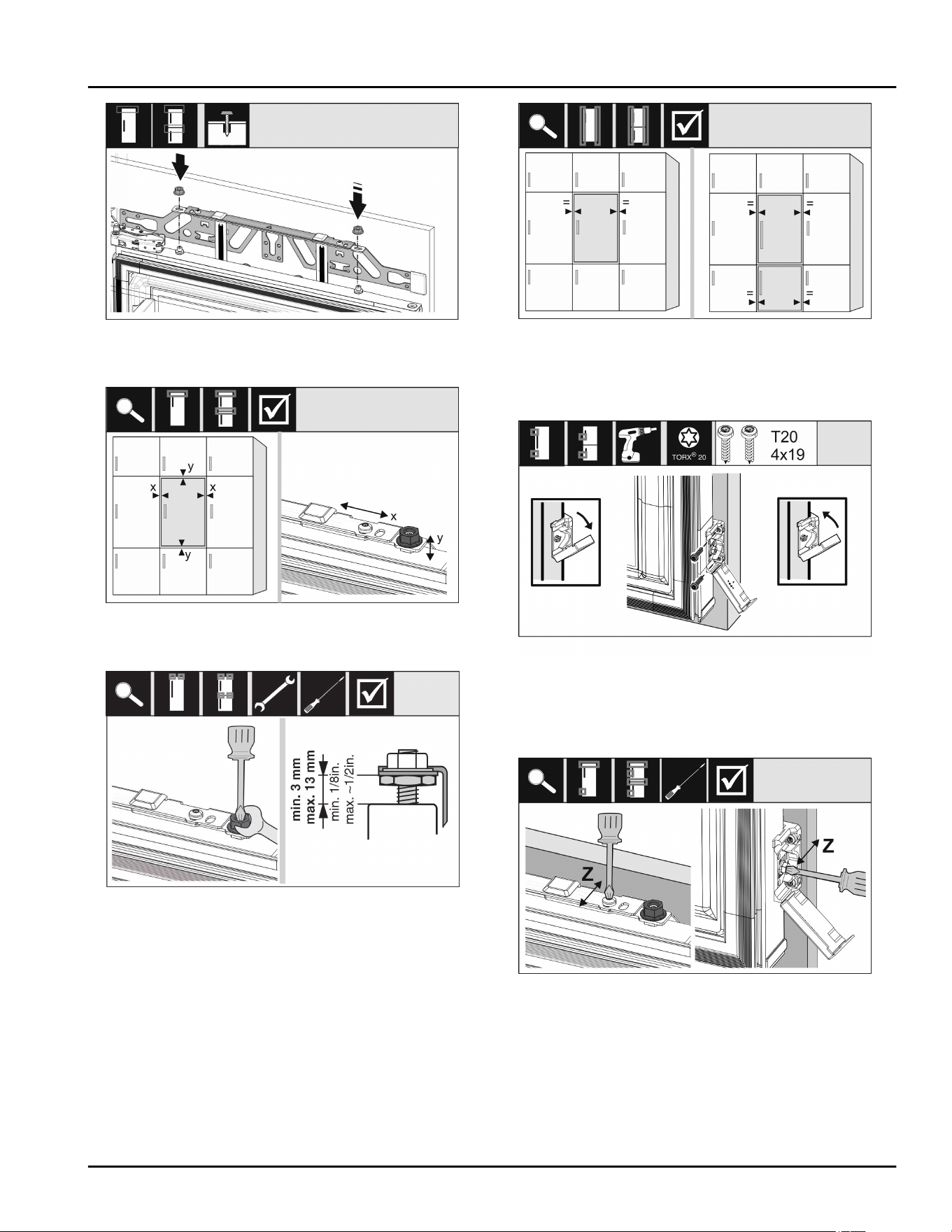
Fig. 57
u
Attach the unit door and loosely screw the lock nuts
onto the adjusting bolts.
Fig. 58
u
Align the unit door in the X and Y direction using the
adjusting bolts.
Fig. 59
u
Screw on the lock nuts and check the height.
Fig. 60
u
Check the gap between the door and the surrounding
custom panels. For unit fronts thicker than 3/4 in.
(19 mm), take account of the dimensions and advice in
the Unit fronts chapter.
Fig. 61
u
Open the cover to fit the mounting bracket on the
custom panel. Align the front edge of the mounting
bracket parallel with the custom panel edge and screw
the bracket down tightly. Fold up the cover.
Fig. 62
Align the unit door in the Z direction:
u
Loosen the adjusting screw on the crosspiece and the
screw on the mounting bracket.
u
Move the door.
Fit the appliance into the recess
18 * Depending on model and options
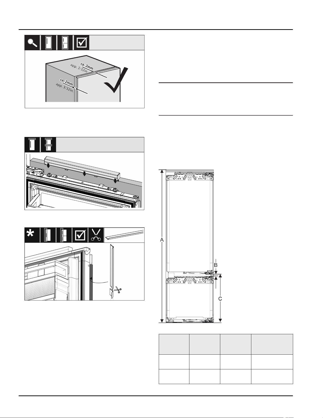
Fig. 63
u
Check the gap between the custom panel and the unit
body.
u
Check all screws and retighten them if necessary.
Fig. 64
u
Clip the top cover on.
Fig. 65
u
Cut the tread to size and place between the front of the
cabinet and the door.
Check the following points to ensure the appliance is
correctly installed. Otherwise, ice and condensation may
form, and malfunctions may occur:
w
The door must close properly.
w
The unit door must not touch the body of the unit.
w
The seal on the upper corner on the handle side must
be fitted securely.
16 Cabinet fronts
16.1 Dimensions
Depending on your model, you will need one or two
cabinet doors. The size of the cabinet door(s) depends on
the overall recess size and cabinet unit thickness.
Note
Observe the appliance and recess dimensions and follow
the installation diagrams (see 3 Appliance dimensions)
(see 4 Recess dimensions) . See the relevant catalog for
the installation diagrams.
General requirements:
-
Please refer to our catalogs for appliance-specific
recommendations on size and weight for fixed door
installations.
-
The cabinet unit thickness should be at least 5/8 ''
(16 mm) and no bigger than 3/4 '' (19 mm).
-
When mounting a 2-door cabinet door, observe the
recommended clearance.
Fig. 66 Clearances for a 2-door
cabinet door
Recess
height
Appliance
height (A)
(in.)
Distance
(B) (in.)
Clearance (C)
fixed door (in.)
178-2
drawers
69–11/16 19/32 21-39/64 +
19/32
178-3
drawers
69–11/16 19/32 27-3/8 + 19/32
Cabinet fronts
* Depending on model and options 19
Other cabinet door above, below or next to it:
-
Vertical gap between cabinet doors must be 3/16 ''
(4 mm).
-
Horizontal gap between cabinet doors must be 3/16 ''
(4 mm). Check the collision factors here
(see 16.3 Setting the clearance to avoid collision) .
Weight and hinges:
-
Heavy cabinet fronts increase the stress on the hinge.
The hinge may be damaged. As such, refer to the
catalog for the maximum weight specification for your
appliance.
-
If the cabinet front exceeds the maximum permitted
weight, an appliance with door-tracking device can help
by loading the weight over several concealed hinges on
the cabinet.
-
If you have long cabinet fronts that protrude a long way
above the appliance, we recommend an additional door
hinge (e.g. Kamat), which by design has the same pivot
point as the fixed door hinge used by Liebherr appli-
ances. Using an additional hinge (Kamat) loads the
weight over multiple points. We recommend using a
milled adapter fitting for high cabinet fronts to coun-
teract any dragging (convex/concave).
16.2 Mounting the cabinet front(s)
When installing, note:
- Cabinet front must be installed symmetrically to the
refrigerator door.
- Adjoining cabinet front is exactly level.
- Adjoining cabinet front has the same edge radius as
the front of the appliance.
- Cabinet front is flat and tension-free.
- Cabinet front is adjusted to a minimum depth of approx.
1/16 '' (2 mm) to the unit body.
u
Fit the appliance into the recess (see 15 Fit the appli-
ance into the recess) .
u
Attach the cabinet front to the appliance door
(see 15 Fit the appliance into the recess) .
u
Check the cabinet front does not collide with anything
(see 16.3 Setting the clearance to avoid collision) .
16.3 Setting the clearance to avoid
collision
After installing the cabinet front(s), check that the cabinet
fronts do not collide.
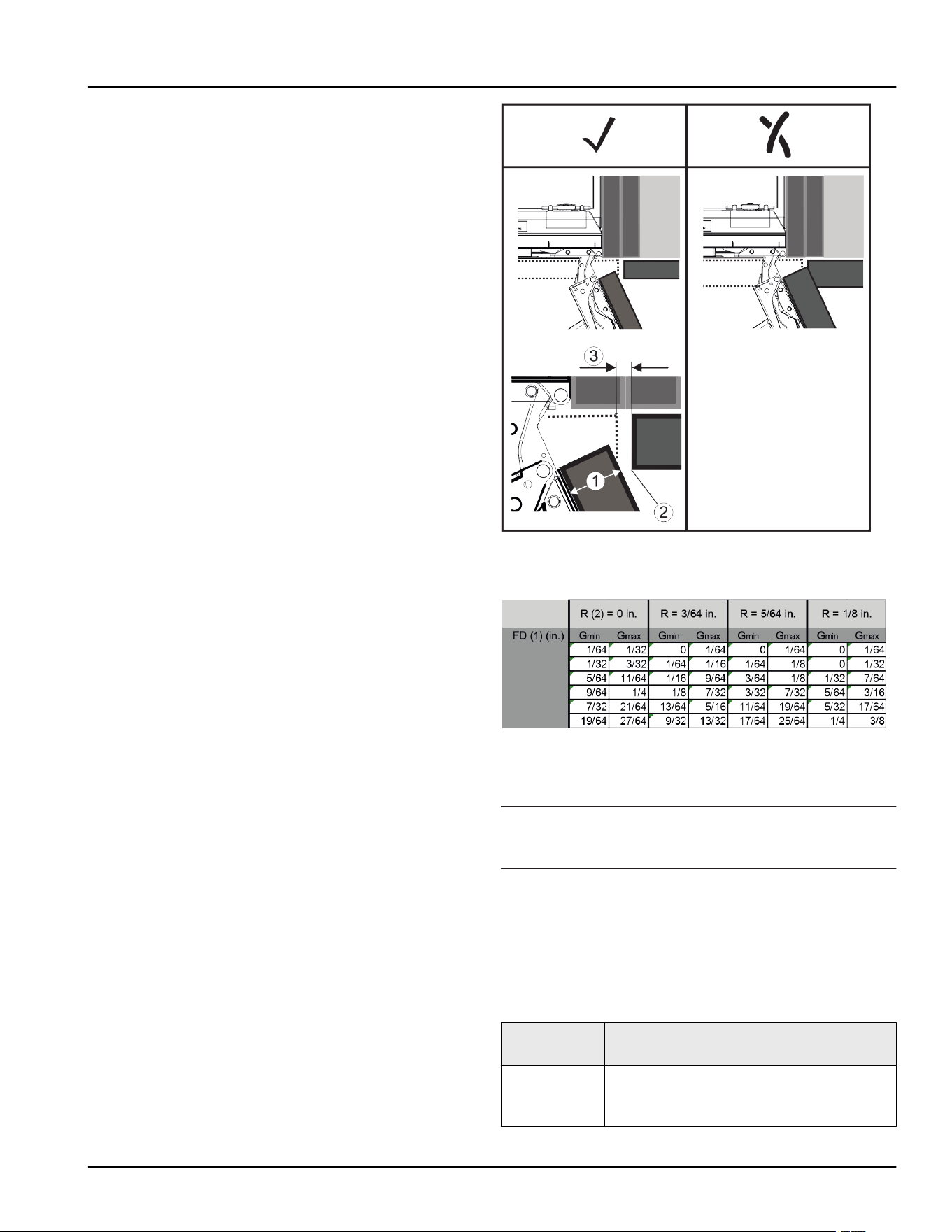
Fig. 67
(1) Front thickness (FD) (3) Clearance size (S)
(2) Edge radius (R)
Fig. 68 Table of min./max. clearances
G
min
= min. clearance in inches
G
max
= max. clearance in inches
Note
When making adjustments, always make sure that the
cabinet front suits the general appearance.
Check the collision factors and adjust them accord-
ingly:
u
Determine the front thickness and edge radius.
u
Refer to the table for the min./max. clearance dimen-
sions.
u
Check the clearance size against the table.
u
Do one of the following depending on the measured
clearance size.
Clearance
size
Description
S > G
max
If the clearance size is greater than the
two limits, you do not need to make any
adjustments.
Cabinet fronts
20 * Depending on model and options
Clearance
size
Description
S < G
min
If the clearance size is below the limits,
you must increase it. Another option is to
increase the edge radius.
G
min
≤ S ≤
G
max
If the clearance is between the two limits,
you have to be careful. This will quickly
lead to collisions.
17 Water tank
Depending on your model, the InfinitySpring water tank is
behind the lowest drawer in the fridge or BioFresh
compartment
17.1 Inserting the water tank
Fig. 69
u
Remove the drawer.
u
Insert the water tank and turn approx. 90° to the right
until it engages.
u
Check that the water tank is sealed and no water leaks
out.
u
Insert the drawer.
u
Vent the water system (see Installation Instructions,
Water Connection)
Instead of the water filter, you can use an additional water
tank.
Note
The water tank is available as a spare part.
18 Water filter
Depending on your model, the water filter is behind the
lowest drawer in the fridge or BioFresh compartment.
It absorbs deposits in the water and reduces the taste of
chlorine.
q
Replace the water filter at least every 6 months under
the specified usage conditions or if the flow rate drops
significantly.
q
The water filter contains carbon and can be disposed of
with the regular household waste.
Note
You can purchase the water filter from the
Liebherr house-
hold appliance store (home.liebherr.com).
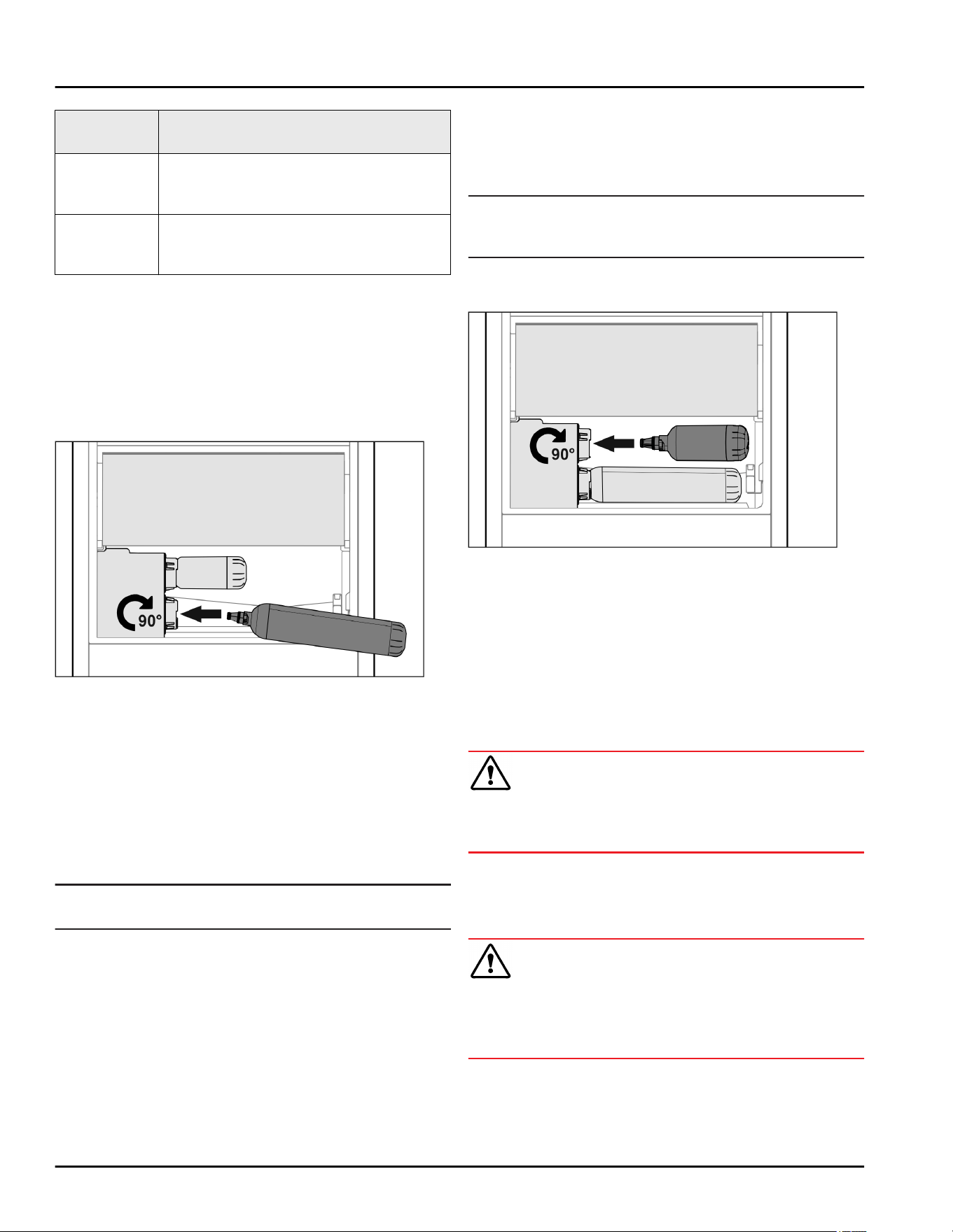
18.1 Installing the water filter
Fig. 70
Make sure that the following conditions are met:
q
Water pressure is maintained (see Installation Instruc-
tions, Water Connection).
u
Remove the drawer.
u
Insert the water filter and turn clockwise approx. 90°
until it engages.
u
Make sure the filter does not leak and no water is
coming out.
u
Insert the drawer.
CAUTION
New water filters may contain particulate matter.
u
Dispense 101.44 fl oz (3 l) of water through the Infinity-
Spring and pour away.
w
The water filter is now ready for use.
19 Connecting the appliance
WARNING
Incorrect connection!
Risk of fire.
u
Do not use an extension cord.
u
Do not use a multipoint connector strip.
Water tank
* Depending on model and options 21

NOTICE
Incorrect connection!
Damage to the electronics.
u
Do not connect the appliance to a stand-alone inverter,
e.g. solar power systems and petrol generators.
u
Do not use an energy saving plug.
Note
Only use the mains cable supplied.
u
A longer mains cable can be ordered from Customer
Service.
Make sure that the following requirements are fulfilled:
- The type of current and voltage at the installation site
complies with the information on the serial tag .
- The socket is grounded and fused in accordance with
regulations.
- The tripping current for the fuse is between 10 and
16 A.
- The socket is easily accessible.
u
Check the electrical connection.
u
Connect the mains plug to the power supply.
w
The Liebherr logo appears on the screen.
w
The display switches to the standby symbol.
Connecting the appliance
22 * Depending on model and options

Connecting the appliance
* Depending on model and options 23

home.liebherr.com/fridge-manuals
Combined fridge-freezer for integrated use, door-on-door
Issue date: 20220328
Part number index: 7088288-00
For Service in the U.S.: Liebherr Service Center
Toll Free: 1-866-LIEBHER or 1-866-543-2437
Service-appliances.us@liebherr.com
PlusOne Solutions, Inc.
3501 Quadrangle Blvd, Suite 120
Orlando, FL 32817
For Service in Canada: Liebherr Service Center
Toll Free: 1-888-LIEBHER or 1-888-543-2437
www.euro-parts.ca
EURO-PARTS CANADA
39822 Belgrave Road, Belgrave, Ontario, N0G 1E0
Phone: (519) 357-3320 | Fax: (519) 357-1326