Loading ...
Loading ...
Loading ...
12
Regulator connections are
3
/
4
" BSP female.
Connection to appliance is
3
/
4
" BSP male.
(Refer to 'Specifications' section for gas supply location dimensions).
NOTE: A Manual Isolation Valve must be fitted to individual appliance supply line.
3. Correctly locate appliance into its final operating position and using a spirit level, adjust legs so that
unit is level and at correct height.
4. Connect gas supply to appliance. A suitable joining compound which resists breakdown action of
LPG must be used on every gas line connection, unless compression fittings are used.
5. Check all gas connections for leakages using soapy water or other gas detecting equipment.
6. Check gas operating pressure is as shown in 'Specifications' section.
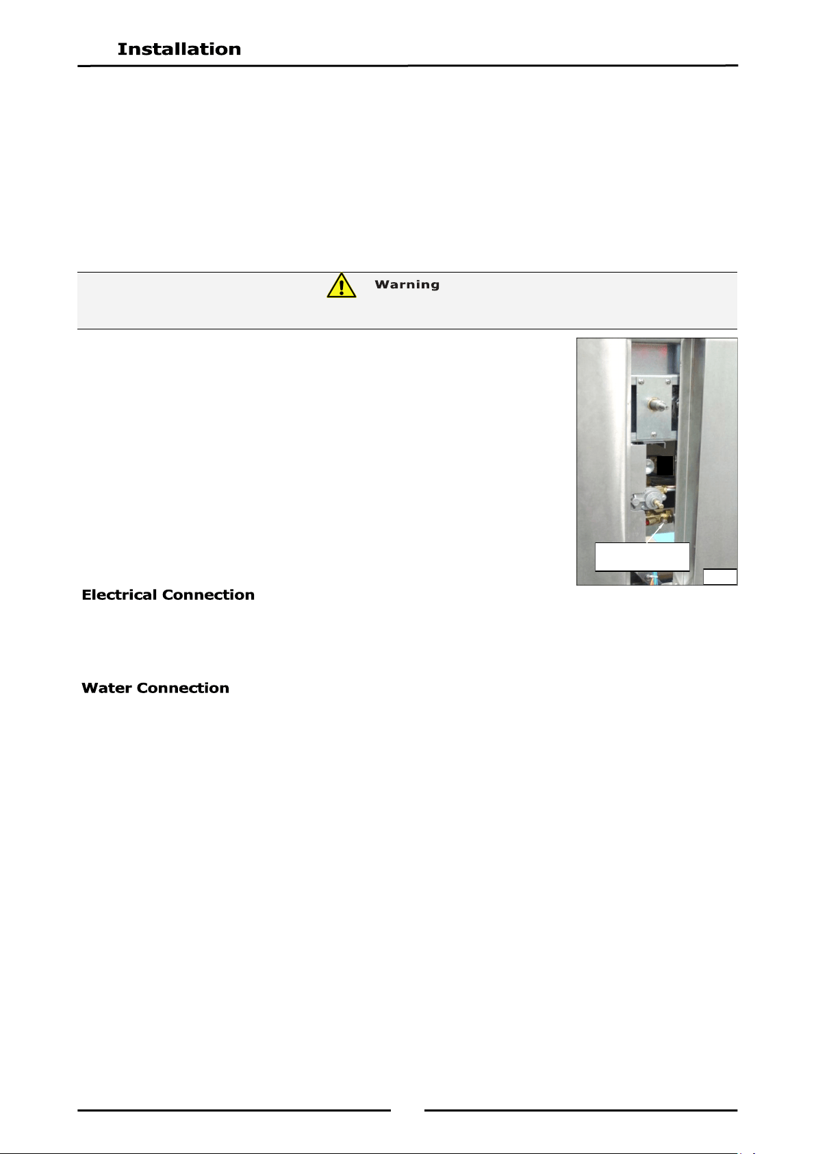
NOTE: Operating pressure is to be measured at gas control outlet
test point with burner operating at ‘High Flame’ setting.
7. Verify operating pressure remains correct.
1. Electrical system are all connected through a 2m, 10amp flex located at LH side of unit.
2. For immediate electric supply, plug lead into a properly earthed, 220-240V, 50Hz, 1P+N+E, 3 pin
socket.
NOTE:
Water supply must be protected by an 'In-Line' sediment filter / strainer, which
should be fitted into pipeline prior to Bratt Pan water connection.
All water pipework must be thoroughly flushed prior to completion of installation
procedure.
Cold water mains ¾” BSP male thread connection point. For location details on services connections refer
to drawings in ‘Specification’ section.
Maximum water supply pressure - 550kPa (80 psi).
Maximum Water Supply Temperature - 80°C.
Remove control panel for access to cold water connection.
This appliance is to be installed in compliance with local water regulations in force.
DO NOT USE A NAKED FLAME TO CHECK FOR GAS LEAKAGES.
Gas Control Outlet
Test Point
Fig 3
Loading ...
Loading ...
Loading ...