90-140 101018
READ THIS PAGE FIRST
1. Howard-McCray would like to thank you for purchasing
one of our units.
PLEASE READ THIS MANUAL CAREFULLY BEFORE
PROCEEDING WITH THE INSTALLATION OR OPERATING
OF THIS UNIT.
2. Environment - These display cabinets are made to operate
at 75°F and 55% relative humidity. Temperature and/or
humidity greater than the factory recommendations will
hinder the performance of this cabinet.
3. Cabinet Set-Up – A qualified refrigeration mechanic should
set-up this cabinet. Time clock and control settings are
extremely critical to the proper operation of this unit. These
settings are the responsibility of the customer and are not
covered by factory warranties. Failure to have this unit
installed by a qualified refrigeration mechanic may VOID all
the warranties on this unit.
4. Location – This cabinet must not be located in the direct
rays of the sun or near radiant heat sources. A minimum of
3" of free air space is required at the rear of the cabinet.
5. Never spray water into the cabinet. This will cause
damage to the seals.
6. If additional assistance is required, please call us at
1-800-344-8222.
READ THIS PAGE FIRST
90-140 101018
Installation and Operating
Instructions For
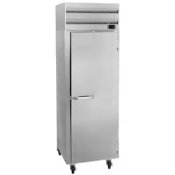
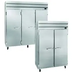
Solid Door Reach-In
SR/SF Series
Important Instructions
Please Read carefully
Before attempting to
install or operate the cabinet
Keep this Book for
Future Reference

Howard-McCray A Division of HMC Enterprises, LLC.
831 East Cayuga Street • Philadelphia, PA 19124 USA • (215) 464-6800 • (800) 344-8222
Fax (215) 969-4890 • E-Mail: [email protected] 101018
1
Table of Contents
Engineering Specifications --------------------------------------------------------------------------------------------------------- 2
Receiving and Inspection------------------------------------------------------------------------------------------------------------- 2
Installation------------------------------------------------------------------------------------------------------------------------------------- 3
Electrical Service Connection------------------------------------------------------------------------------------------------------ 3
Caster or Leg Installation------------------------------------------------------------------------------------------------------------- 3
Condensate Evaporator Pan--------------------------------------------------------------------------------------------------------- 3
Drain Trap Installation------------------------------------------------------------------------------------------------------------------ 3
Start-Up Check-List---------------------------------------------------------------------------------------------------------------------- 4
Start-Up ----------------------------------------------------------------------------------------------------------------------------------------- 4
Temperature Control--------------------------------------------------------------------------------------------------------------------- 4
Defrost ------------------------------------------------------------------------------------------------------------------------------------------ 5
Defrost Time Clock ----------------------------------------------------------------------------------------------------------------------- 5
Defrost Heater------------------------------------------------------------------------------------------------------------------------------- 5
Drain Pan Heater--------------------------------------------------------------------------------------------------------------------------- 5
Defrost Termination Control--------------------------------------------------------------------------------------------------------- 6
Crankcase Pressure Valve----------------------------------------------------------------------------------------------------------- 6
High Pressure Limit Control--------------------------------------------------------------------------------------------------------- 6
Stocking the Cabinet--------------------------------------------------------------------------------------------------------------------- 6
Maintenance Suggestions------------------------------------------------------------------------------------------------------------- 7
The Cleaning Process------------------------------------------------------------------------------------------------------------------- 7
Condenser Cleaning--------------------------------------------------------------------------------------------------------------------- 7
Machine Compartment Cleaning -------------------------------------------------------------------------------------------------- 7
Trouble Chart -------------------------------------------------------------------------------------------------------------------------------- 8
Parts List--------------------------------------------------------------------------------------------------------------------------------------- 9
Customer Installation Record ---------------------------------------------------------------------------------------------------- 10
Warranty -------------------------------------------------------------------------------------------------------------------------- Warranty
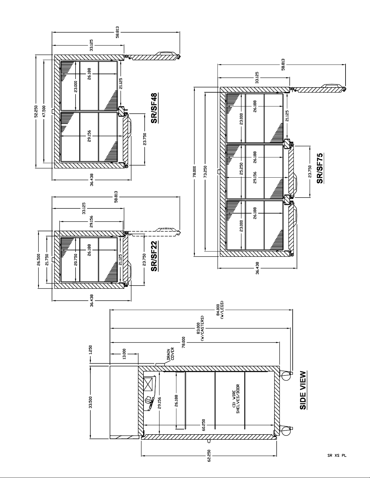
Cross-Sectional View ----------------------------------------------------------------------------------------------------- SR XS PL
Plan View ------------------------------------------------------------------------------------------------------------------------- SR XS PL
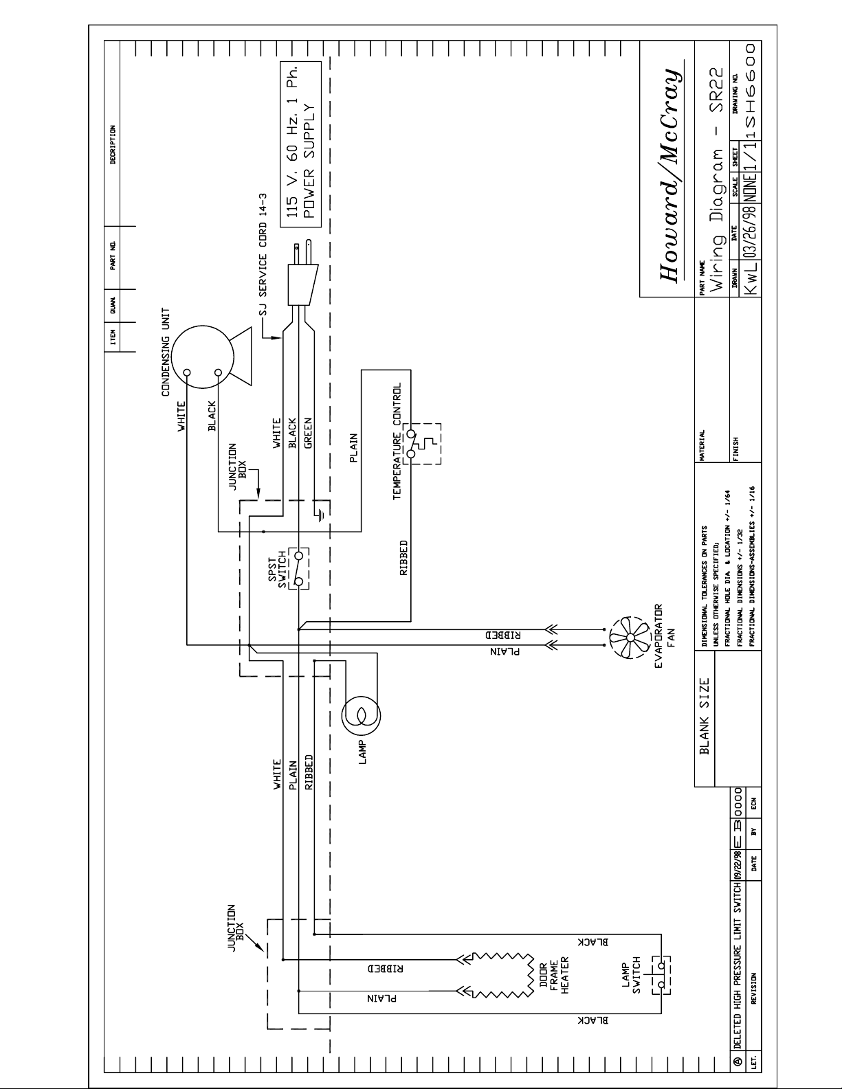
Cabinet Wiring Diagram (SR22)---------------------------------------------------------------------------------------- 1SH6600
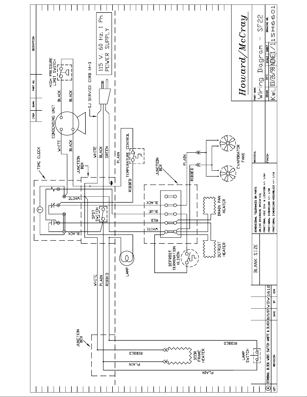
Cabinet Wiring Diagram (SF22) ---------------------------------------------------------------------------------------- 1SH6601
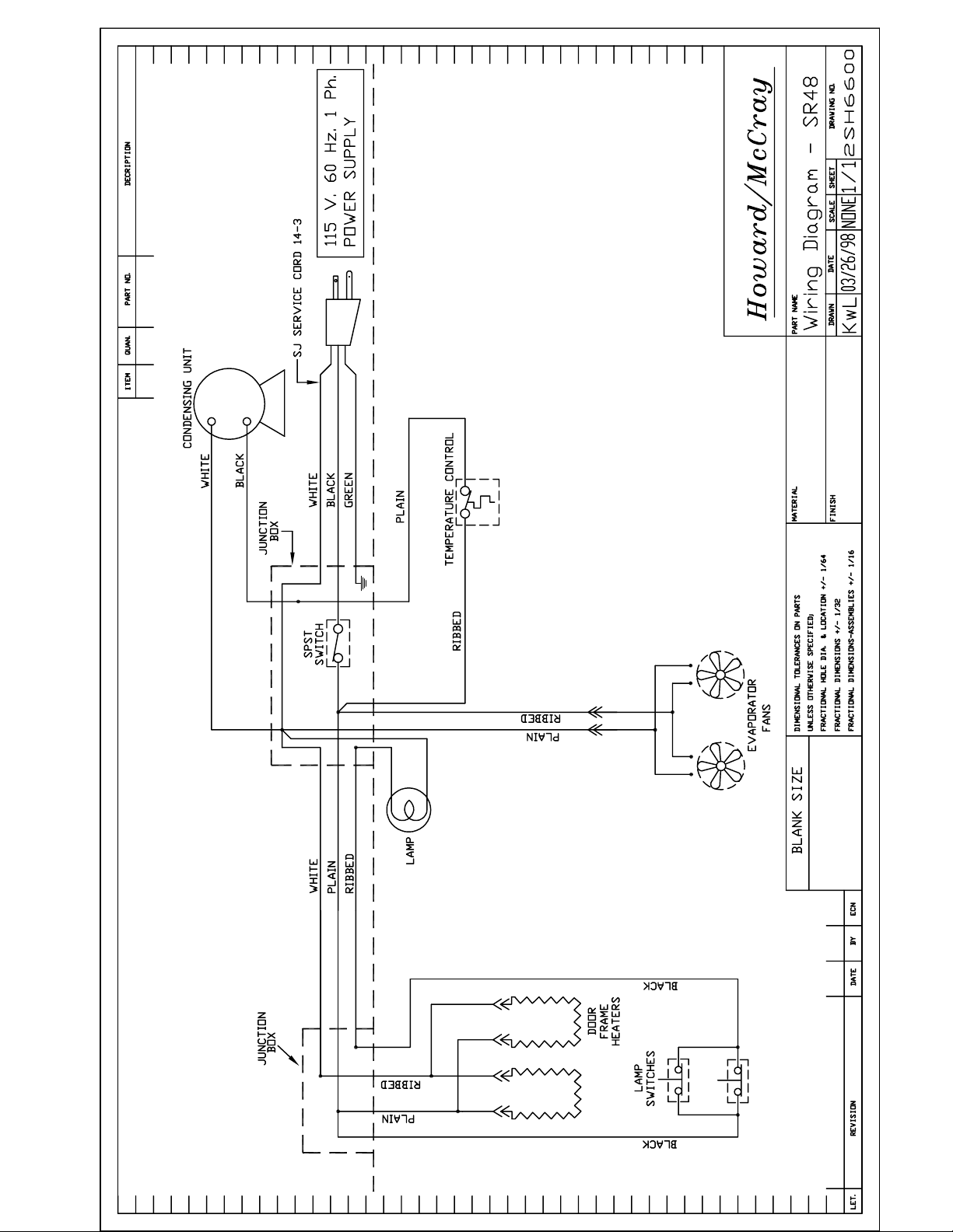
Cabinet Wiring Diagram (SR48)---------------------------------------------------------------------------------------- 2SH6600
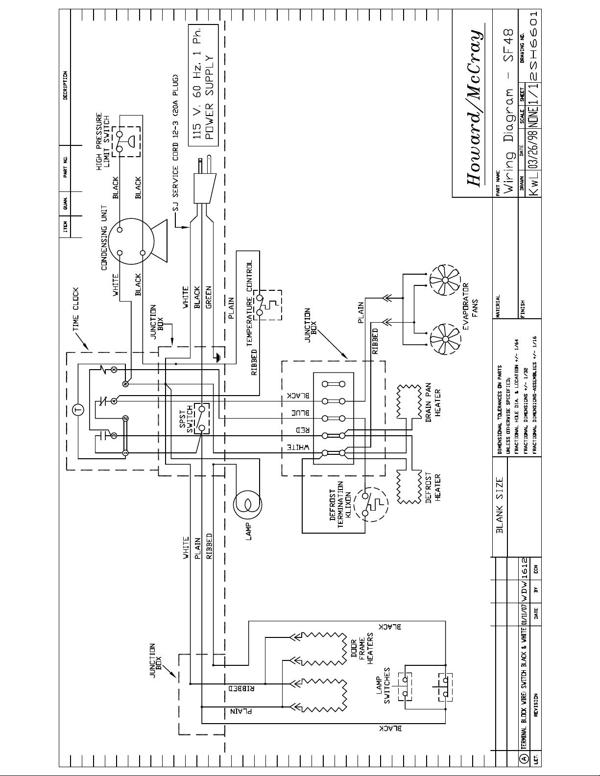
Cabinet Wiring Diagram (SF48) ---------------------------------------------------------------------------------------- 2SH6601
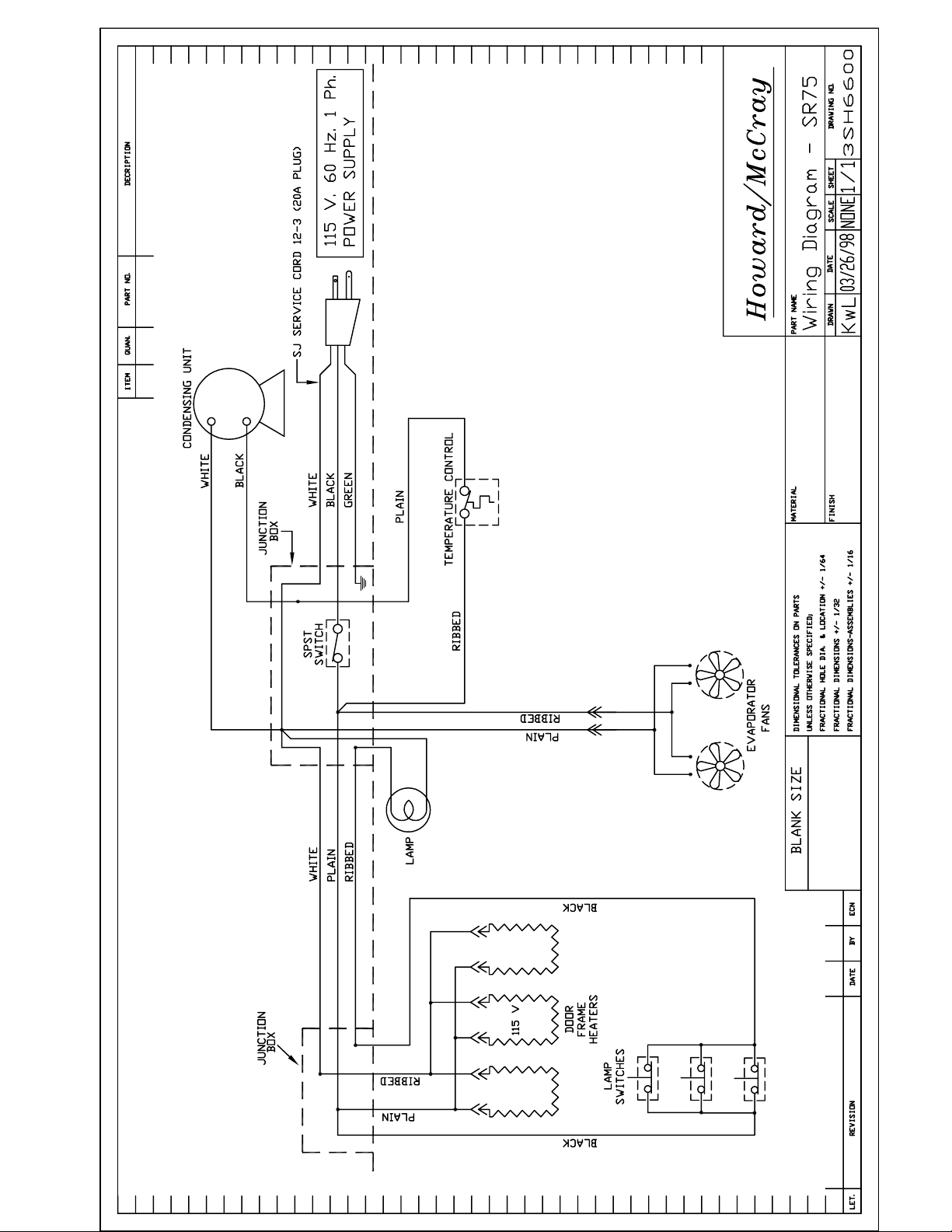
Cabinet Wiring Diagram (SR75)---------------------------------------------------------------------------------------- 3SH6600
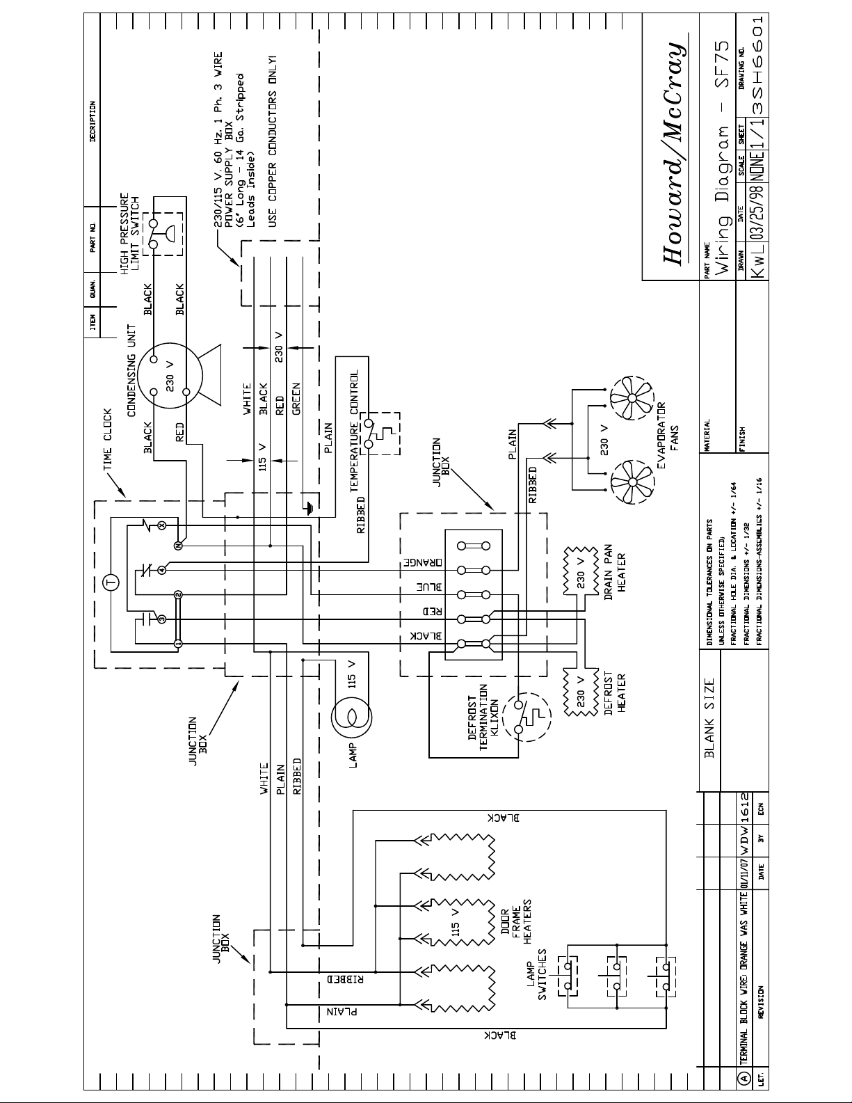
Cabinet Wiring Diagram (SF75) ---------------------------------------------------------------------------------------- 3SH6601
Condensate Evaporator Pan Installation Drawing--------------------------------------------------------- 1SH7788
Leg Installation Drawing-------------------------------------------------------------------------------------------------- 1SH7789
Caster Installation Drawing--------------------------------------------------------------------------------------------- 1SH7790

Howard-McCray A Division of HMC Enterprises, LLC.
831 East Cayuga Street • Philadelphia, PA 19124 USA • (215) 464-6800 • (800) 344-8222
Fax (215) 969-4890 • E-Mail: [email protected] 101018
2
The following instructions are for the benefit of the new owner and the installing contractor.
They should be studied carefully before attempting to install or operate the cabinet.
This manual is the property of the owner and should remain in the owner’s possession.
Engineering Specifications – SR Models
Model No.
Cabinet
Dimensions
D x H* x L
Compressor
HP
Electrical Voltage
Max. Amps
Power Cord
Plug (NEMA)
SR22 35 x 83 x 26 1/2 1/4 115/60Hz/1PH 6.8 5-15P
SR48 35 x 83 x 52 1/4 1/3 115/60Hz/1PH 9.6 5-15P
SR75 35 x 83 x 78 1/2 115/60Hz/1PH 12.1 5-20P
Engineering Specifications – SF Models
Model No.
Cabinet
Dimensions
D x H* x L
Compressor
HP
Electrical Voltage
Max. Amps
Power Cord
Plug (NEMA)
SF22 35 x 83 x 26 1/2 1/2 115/60Hz/1PH 9.5 5-15P
SF48 35 x 83 x 52 1/4 3/4 115/60Hz/1PH 7.9 5-20P
SF75 35 x 83 x 78 1 115/208-
230/60Hz/1PH
8.6 N/A
* - Includes 5" Casters
These cabinets are designed to operate in an air conditioned location ONLY.
Temperature not to exceed 75
o
F and a relative humidity not to exceed 55%.
Receiving and Inspection Procedure
1) The cabinet has been carefully operation
tested and inspected before crating and has
been determined to be in good operating
condition before leaving the factory.
2) Upon arrival of the cabinet, the crate should be
inspected thoroughly for any damage that may
have occurred in transit. In the event that any
damage is discovered, it should be noted on the
delivery ticket or Bill of Lading and signed to that
effect. An immediate claim should then be filed
against the carrier giving them the description
and amount of damage.
3) After the crate has been removed, the cabinet
should be examined carefully for any damage. If
there is any concealed damage, the carrier
should be notified immediately. Make a request in
writing with the carrier for an inspection within 15
days, and retain all packaging. The carrier will
supply the inspection report and the required
claim forms.
4) Our Company can assume no responsibility for
filing freight claims as the cabinet was in good
condition on a clear Bill of Lading, F.O.B.
Philadelphia. However, the factory will assist, if
required.
5) Shortages - Check your shipment for any
possible shortages of material. If one exists and
is found to be responsibility of Howard-McCray,
notify the factory. Howard-McCray will
acknowledge shortages within ten days from
receipt of acknowledgement. If a shortage exists
and it involves the carrier, notify the carrier
immediately and request an inspection.

Howard-McCray A Division of HMC Enterprises, LLC.
831 East Cayuga Street • Philadelphia, PA 19124 USA • (215) 464-6800 • (800) 344-8222
Fax (215) 969-4890 • E-Mail: [email protected] 101018
3
Installation
As with any refrigerated cabinet, there are
several very important requirements that must be
complied with for proper operation. They are as
follows:
1. This line of cabinets are designed to operate in
a location with an ambient temperatures of 75
o
F
and a relative humidity of 55%. This cabinet
should not be located in an area the cabinet may
be subjected to radiant heat from spot or flood
lamps, sun rays or heat from suspended gas
heating fixtures.
2. After locating the cabinet, it must be leveled
from front to back as well as end-to-end. This will
facilitate proper refrigeration at the evaporator
and proper dissipation of the defrost water.
3. The minimum clearance allowed for the rear of
the cabinet is 3 inches and the sides can have no
clearance if need be.
4. All wiring must be installed by a competent
electrician and conform to local codes. The
incoming voltage must be maintained to within 5%
of the voltage shown on the cabinet nameplate.
Electrical Service Connection
Some of the models are provided with a Service
Power Cord, see the Engineering
Specifications for the plug type of your cabinet.
Locate the electrical outlet in such a manner that
you may plug in the service cord directly, without
the use of an extension cord. The electrical outlet
used to supply the cabinet must have proper
ground facilities to match the service plug on the
cabnet service cord. Make sure that no other
electrically operated devices are connected to
the circuit operating this cabinet, which will cause
an overload. Overloaded circuits are extremely
hazardous.
The electrical connection for models that are not
supplied with a Service Power Cord is to be made
in junction box located at the rear of the cabinet
(see applicable Plan View drawing for exact
location).
The incoming voltage must be maintained to
within 5% of the voltage shown on the nameplate.
Howard-McCray will not accept responsibility for
the performance of the cabinet or malfunction of
any component due to a incorrect voltage supply
than that indicated on the serial rating plate. Use
separate electrical supply lines connected to a
fuse block or circuit breaker of proper capacity.
Caster or Leg Installation
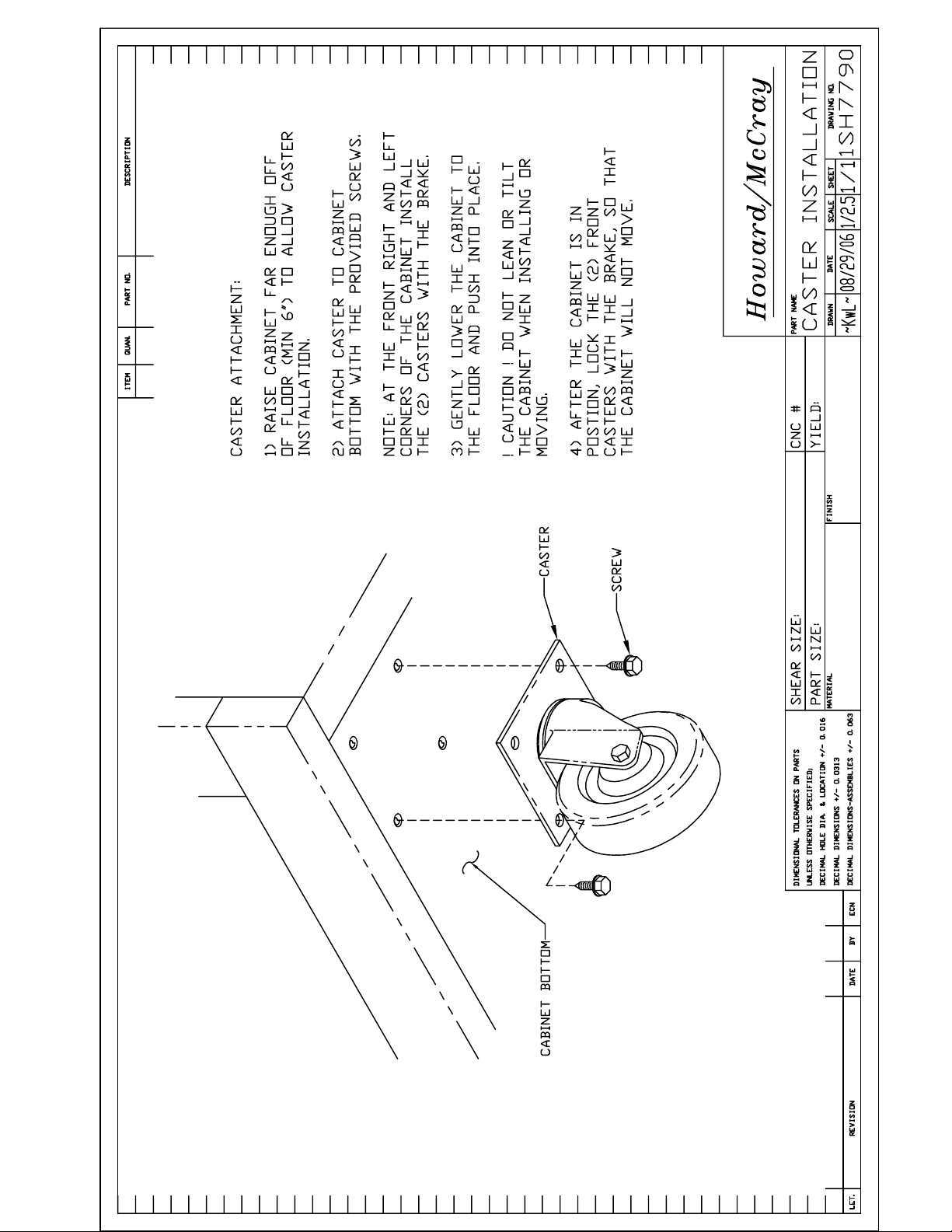
Most cabinets are supplied with a set of casters.
These casters are shipped as separate items and
will need to be installed before the cabinet is
located in position. See the Caster Installation
drawing for exact instructions.
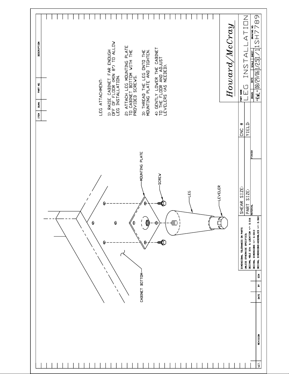
Some cabinets are ordered and supplied with
adjustable legs. These legs and mounting plates
are shipped as separate items and will need to be
installed before the cabinet is located in position.
See the Leg Installation drawing for exact
instructions.
NOTE When installing either Casters or Legs,
take all necessary safety precautions when
elevating the cabinet.
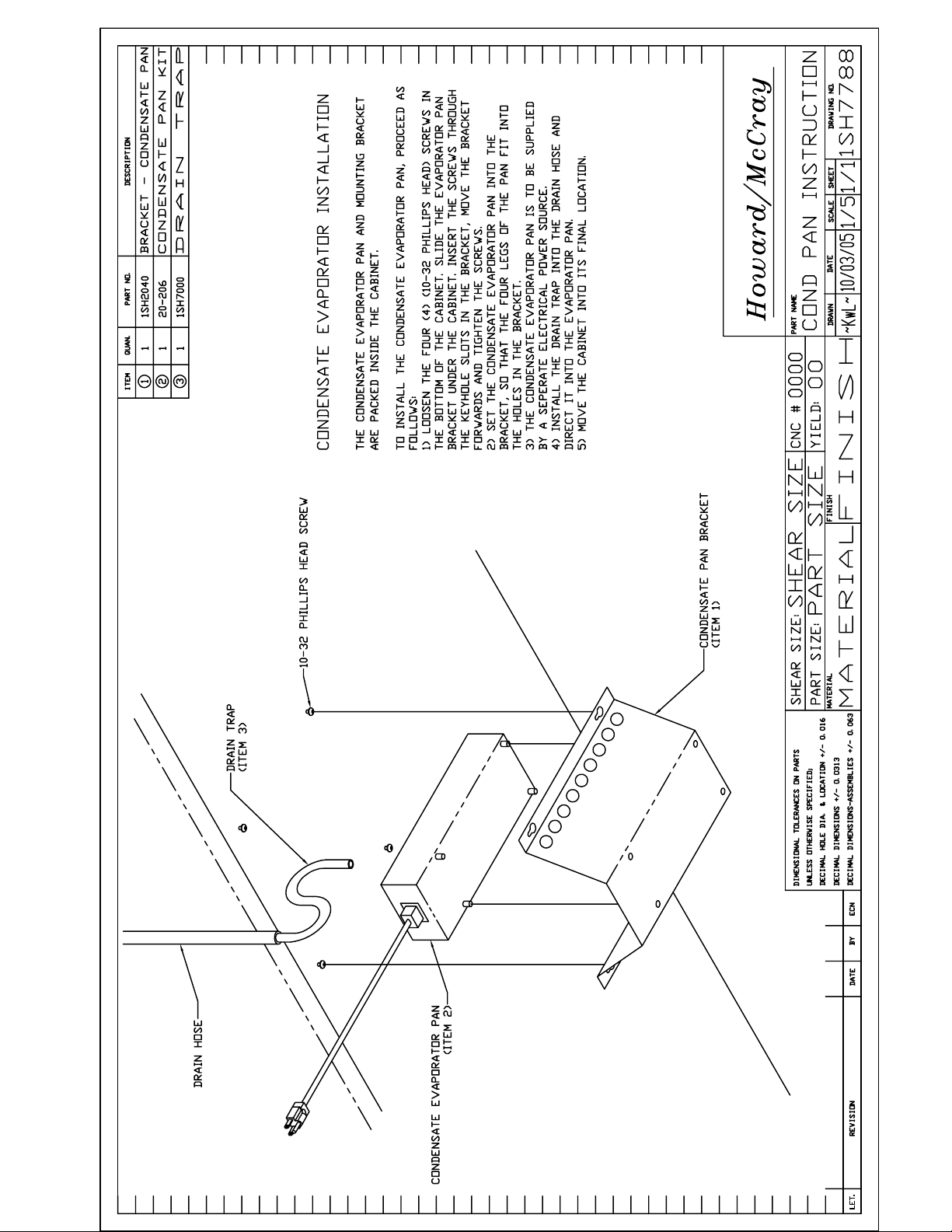
Condensate Evaporator Pan
An electric condensate evaporator pan is
furnished with the cabinet, to dissipate the water
collected from the coil during defrost or off cycle.
The evaporator pan and it's mounting bracket are
shipped as a separate items. The evaporator pan
is equipped with a power cord for plugging into a
115VAC NEMA 5-15R outlet. To install the
evaporator see the Condensate Pan
Instruction drawing for exact instructions.
Drain Trap Installation
A properly installed drain trap is extremely
important in ensuring satisfactory cabinet
operation, and protection from product loss. The
drain hose on this model is factory attached to the
rear of the cabinet. The drain hose is supplied at
a length sufficient to reach the floor, when the
cabinet is equipped with either casters or legs.
After installing the factory supplied Electric
Condensate Pan loosen the drain hose
attachement clamps that hold the drain hose in a
loop. Configure the drain hose on the rear of the
cabinet so that it is oriented vertically to the
condensate pan. Locate the factory supplied
drain trap so that it exits (in a vertical orientation)
into the Electric Condensate Pan. Determine
where the drain hose will overlap the drain trap
by a minimum of 2" and cut the hose to this
length. Insert the drain trap into the drain hose
and secure them to the rear of the cabinet.
NOTE Never route the drain hose directly into the
Electric Condensate Pan, the heat of the pan will
damage the drain hose.

Howard-McCray A Division of HMC Enterprises, LLC.
831 East Cayuga Street • Philadelphia, PA 19124 USA • (215) 464-6800 • (800) 344-8222
Fax (215) 969-4890 • E-Mail: [email protected] 101018
4
CHECK-LIST FOR USE BEFORE START-UP
The following items should be checked, when
applicable to the cabinet:
Make sure that the door gaskets make a proper
seal to the cabinet.
Make sure that all fan motors are properly
plugged in.
Make sure that all fan blades are tight on all fan
motor shafts.
Make sure that the expansion valve sensing bulb
is properly positioned and is tightly secured.
Make sure that all flare nuts are tight.
Make sure that tubing entrance holes both inside
and outside the cabinet are properly sealed.
Make sure that all SEALANT MATERIAL that was
removed from position in the cabinet during
installation and piping is correctly replaced and
seals in a satisfactory manner.
Make sure that all the loose debris in the cabinet
is removed.
Start-Up
1. Electrically energize the cabinet. Check the
supply voltage, must be within +/- 5%. Check the
evaporator fan motors to ensure all are operating
and rotating in the correct direction.
2. Electrically energize the refrigeration system.
Check the supply voltage, must be within +/- 5%.
3. Set and check the Temperature Control
settings (as outlined in the Temperature Control
section below).
4. Verify refrigeration system is operating
properly.
5. Verify proper Defrost operation (as outlined in
the Defrost section).
6. Set the Defrost Time clock to the correct time-
of-day (as outlined in the Defrost Time Clock
section).
7. Verify the proper setting of the Crankcase
Pressure Valve (as outlined in the Crankcase
Pressure Valve section).
Temperature Control
The temperature control, when it leaves the
factory, is set to the normal position, which will
provide a proper average desired temperature
for the cabinet type. The control may have to be
adjusted to satistfy the owner's requirements, or
local conditions.
Temperature in the cabinet is controlled with a
thermostat located in the evaporator housing.
Turning the control selector to the right lowers the
cabinet temperature. Turning the control selector
to the left raises the cabinet temperature. DO
NOT attempt to operate freezer models lower
than 0
o
F. Operating freezer models lower than
0
o
F provides no additional protection to food
products but will result in excessive run time and
possible ice build up on the evaporator.
Howard-McCray A Division of HMC Enterprises, LLC.
831 East Cayuga Street • Philadelphia, PA 19124 USA • (215) 464-6800 • (800) 344-8222
Fax (215) 969-4890 • E-Mail: [email protected] 101018
5
Defrost
These freezer models utilize an electric defrost
system. This sytem is self-initiating/self-
terminating and consists of the following
components:
• A Time Clock to initiate the defrost cycle,
terminate the cooling cycle and stop the
evaporator fans.
• A Defrost Heater that heats the evaporator
coil to remove the accumulated frost and ice.
• A Drain Pan Heater to warm the drain pan to
allow the condensate water to drain out of the
cabinet.
• A Defrost Termination Control to signal the
end of the Defrost cycle.
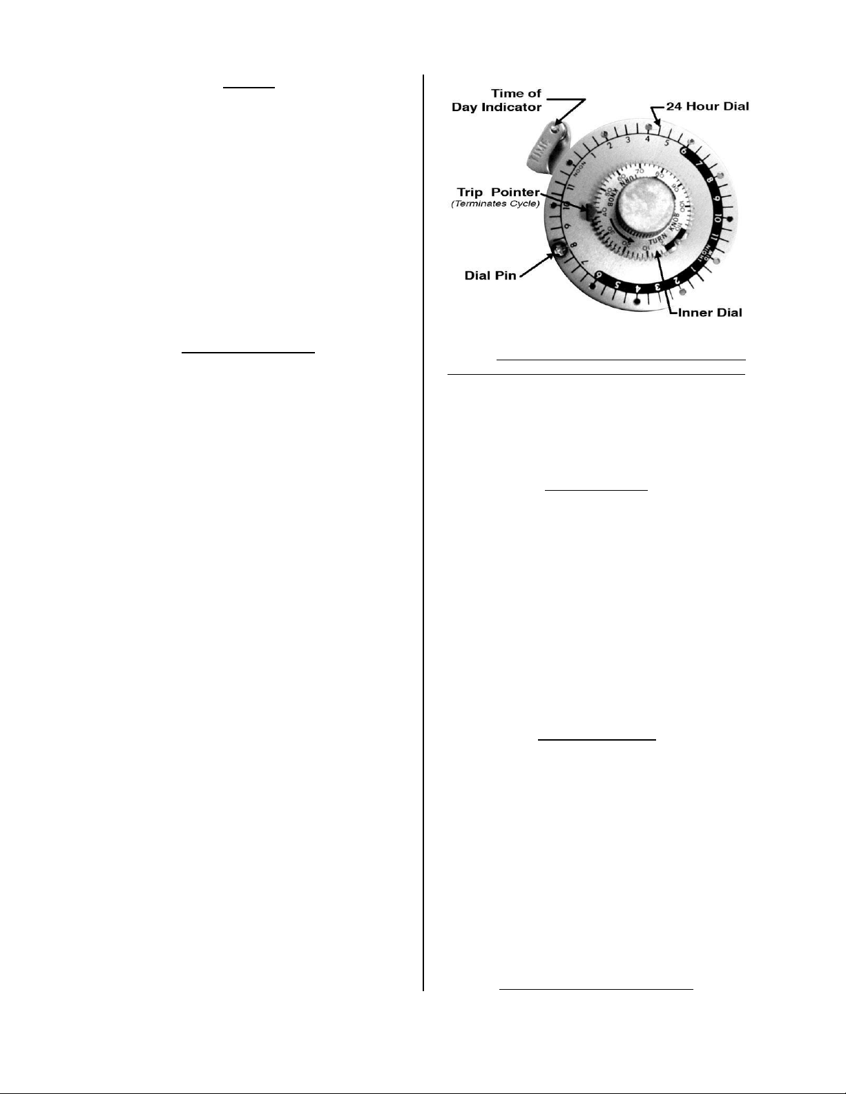
Defrost Time Clock
The time clock supplied with this cabinet is a time
initiated, signal terminated timer, with a fail-safe
time-out feature. The timer is located in the
machine compartment of the cabinet. Under
normal operating conditions, one (1) to three (3)
defrost periods per day should be satisfactory.
The recommended fail-safe setting is 20 minutes.
The evaporator fans will not operate during the
defrost period.
Timer Adjustment Instructions
To set the number of defrost periods: Four pins
are furnished with each timer. These pins can be
screwed into the outer (24 hour) dial of the timer
at the hours when defrost is desired.
To set the time of day: Grasp the knob in the
center of the inner (2 hour) dial and rotate in a
counter-clock-wise direction. This will revolve the
outer dial to align with the pointer. Use the outer
dial for the hour and the inner dial for the minutes.
Note: Do Not try to set the time control by
grasping the outer dial. Rotate the inner dial only.
To set the fail-safe cycle length: Push down the
copper pointer on the inner (2 hour) dial and
rotate to the desired time. The numbers on the
dial are in minutes.
Defrost Heater
The defrost heater is pressed into the underside
of the evaporator coil fins. The heat from the
heater rises into the evaporator and melts the
frost and ice that has accumulated on the coil.
To check if the defrost heater is operating
properly first verify that it recieving the proper
voltage with a voltmeter. Use an ammeter to
check for the proper current draw of the heater.
The amps for the heaters are as follows:
• SF22: 5.2A @ 115V
• SF48: 9.5A @ 115V
• SF22: 4.8A @ 230V
Drain Pan Heater
The drain pan heater is attached to the drain pan
with aluminum tabs. The drain pan heater warms
the drain pan so that the consensate water from
the evaporator coil will not freeze to the pan, and
will drain freely out of the cabinet.
To check if the defrost heater is operating
properly first verify that it recieving the proper
voltage with a voltmeter. Use an ammeter to
check for the proper current draw of the heater.
The amps for the heaters are as follows:
• SF22: 3.5A @ 115V
• SF48: 3.5A @ 115V
• SF22: 1.7A @ 230V
Defrost Termination Control

Howard-McCray A Division of HMC Enterprises, LLC.
831 East Cayuga Street • Philadelphia, PA 19124 USA • (215) 464-6800 • (800) 344-8222
Fax (215) 969-4890 • E-Mail: [email protected] 101018
6
These freezer models utilize a non-adjustable
sealed thermostat as a defrost termination
switch. It is located in the evaporator housing on
the evaporator coil suction line.
The defrost termination control senses the
temperature inside the evaporator housing. When
the temperature, during the defrost cycle,
reaches 50
o
F it closes it's contact signalling the
defrost time clock to terminate the defrost cycle.
The differential setting of the defrost termination
control is 30
o
F, and will not open it's contact until
the temperature inside the evaporator housing
pulls down to 20
o
F. If the defrost termination
control fails to terminate the defrost cycle, the
defrost time clock will stop the defrost cycle after
the amount of time set by the fail-safe on the
defrost time clock.
Crankcase Pressure Valve
(Freezer Models)
Some freezer models utilze a crankcase pressure
valve to protect the compressor against
excessive suction pressure, during initial start-up
and upon termination of the defrost cycle. This
valve is factroy set to limit the compressor
suction pressure to 20 PSIG, and should not be
changed.
To check this setting, it is necessary that the
pressure on the inlet side, or evaporator side, of
the valve be above 20 PSIG. If not checking
during the start-up, place the cabinet into the
defrost cycle, to obtain a raised evaporator
suction pressure. With a guage installed on the
suction service valve, check for the proper
setting after the defrost cycles terminates. This
setting should be checked several times before
leaving the installation.
High Pressure Limit Control
(Freezer Models)
The cabinet is equiped with a High Pressure Limit
Control. This control is for Safety purposes, and
SHOULD NOT BE ADJUSTED UNDER ANY
CIRCUMSTANCES.
Stocking the Cabinet
After the cabinet has been started up, it should
be operated for a sufficient length of time to bring
the storage temperature down to cause the
thermostat to cycle the condensing unit. For
refrigerator models, three to four hours is usually
sufficient. For freezer models, allow at least four
to six hours is usually sufficient.
Do not load cabinet beyond shelf size limits; this
will disturb the air flow within the cabinet. Do not
allow any of the product to obstruct the fan
guards, this will have a negative effect on the
cabinet's cooling capability.
Howard-McCray A Division of HMC Enterprises, LLC.
831 East Cayuga Street • Philadelphia, PA 19124 USA • (215) 464-6800 • (800) 344-8222
Fax (215) 969-4890 • E-Mail: [email protected] 101018
7
Maintenance Suggestions
An attractive operation can be a very profitable.
Dirty and poorly merchandised cabinets are
offensive to most discriminating customers, so a
clean attractive cabinet will pay dividends.
Weekly or more often, if necessary, the display
area should be cleaned and attractively stocked.
Important Notice
1. ALWAYS disconnect the power to the cabinet
before attempting to clean it with any liquid.
2. NEVER under any circumstances should a
water hose be sprayed into this cabinet.
3. NEVER use ammonia or solutions with
ammonia on this cabinet.
4. The use of abrasive cleaning materials on this
cabinet will VOID all cabinet warranties.
The Cleaning Process
1. Turn the power off from the source.
2. Remove all merchandise from the cabinet
and store in a refrigerated area. Then remove
all shelves and floor pans.
3. This cabinet can be hand cleaned internally
with a mild soap detergent and hot water.
Diluted non-chlorine bleach and hot water is a
good sanitizer. The cleaning cloth should be
just wet enough to get a reasonable cleaning
action but should not be wet to a point where
it will emit a large amount of water which will
flow through the drain system causing it to
overflow.
4. After the cabinet is cleaned, any remaining
water in the cabinet can be soaked up with
the use of a sponge and dried out with a dry
cloth completely before resuming operations.
5. Make sure that the internal drain is open and
remove all scraps, paper, and lint.
6. All external panels may be cleaned with a
damp cloth, and then they may be polished
with a dry lint free cloth. This will preserve
the luster of the cabinet.
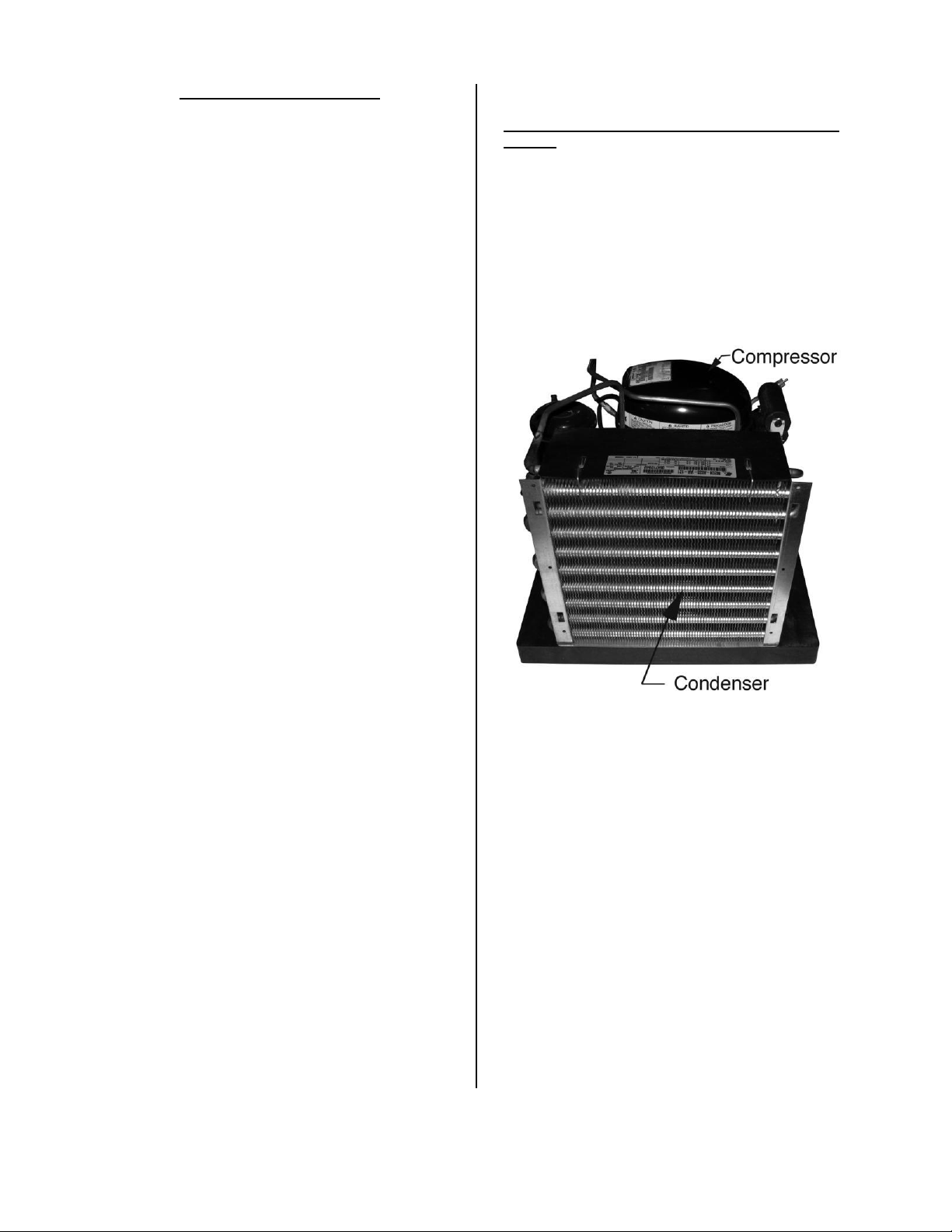
Cleaning the Condenser
It is crucial that the condenser face be cleaned
weekly. The condenser is prone to quickly
accumulate any dust or dirt from the location. A
dirty condenser will diminish the cooling ability of
the system, thus resulting in longer operational
times and warmer product temperatures.
The condenser face can be cleaned with the use
of a hose/brush attachment on a vacuum cleaner.
Take care to aviod bending the condenser fins, It
is of vital importance that the condenser gets the
proper amount of air through the fins and around
the tubes, therefore all dirt, lint, and dust needs to
be removed.
Cleaning the Machine Compartment
At intervals of four to six months, or before if
necessary, it is recommended that the Machine
Compartment be cleaned out. It should be
accomplished in the following order:
1. Shut down the cabinet electrically.
2. Remove the front grille. Using a hose/brush
attachment on a vacuum cleaner, all dirt, store lint
and dust can be removed from the machine
compartment.
3. If any traces of oil are found contact your
Refrigeration Service person as soon as
possible.
4. Before reloading the cabinet with
merchandise, allow an hour for refrigeration pull-
down. Make sure that all merchandise is in a
good salable and refrigerated condition when re-
loading the cabinet.

Howard-McCray A Division of HMC Enterprises, LLC.
831 East Cayuga Street • Philadelphia, PA 19124 USA • (215) 464-6800 • (800) 344-8222
Fax (215) 969-4890 • E-Mail: [email protected] 101018
8
Trouble Chart
A. Compressor will not start - no hum
Possible Causes:
1. Disconnect switch open
2. Blown fuse
3. Defective wiring
4. Overload protector tripped
5. Open control contacts (control may be
defective, or unit location may be too
cold)
6. Defective overload protector
B. Compressor will not start - hums but cycles on
overload
Possible Causes:
1. Low voltage
2. Unit wired incorrectly
3. Starting capacitor defective
4. Starting relay contact not closing
5. Compressor motor defective
6. High head pressure
7. Bearings on pistons tight - low oil charge
C. Compressor starts, but starting winding
remains in circuit
Possible Causes:
1. Low voltage
2. Unit wired incorrectly
3. Starting capacitor weak
4. Running capacitor defective
5. Starting relay defective
6. Compressor motor defective
7. High head pressure
D. Compressor starts and runs but cycles on
overload
Possible Causes:
1. Low voltage
2. Running capacitor defective
3. Overload protector defective
4. High head pressure
5. Fan motor, pump, etc., wired to wrong
side of overload protector
6. Compressor motor partially grounded
7. Unbalanced line voltage (3 phase models)
8. Bearing or pistons tight - low oil charge
E. Compressor short cycles
Possible Causes:
1. Control differential set too close
2. Refrigerant undercharge
3. Refrigerant overcharge
4. Discharge valve leaking
5. Expansion valve leaking
6. Cutting out on high pressure control
7. Cutting out on overload protector because
of tight bearings, stuck piston, high head
pressure or restricted air cooled
condenser
F. Compressor tries to start when thermostat
closes but cuts out on overload, starts after
several attempts
Possible Causes:
1. Low voltage
2. Thermostat differential too close (lower
than 10°)
3. Thermostat bulb not in tight contact with
evaporator
G. Running cycle too long, or unit operated
continuously
Possible Causes:
1. Insufficient refrigerant charge
2. Dirty or restricted condenser
3. Unit: location too hot
4. Control contacts stuck
5. Air or other non-condensable gases in
system
6. Expansion valve plugged or defective
7. Cabinet doors left open too long
8. Insufficient, defective or water - logged
insulation
9. Evaporator coil plugged with ice or dirt
H. Evaporator temperature too high
Possible Causes:
1. Shortage of refrigerant, or leak on system
2. Restricted capillary tube, strainer or drier
3. Control setting too high
4. Expansion valve restricted
5. Expansion valve too small
6. Evaporator coil plugged with ice or dirt
7. Evaporator oil logged
I. Noisy Unit
Possible Causes:
1. Compressor oil charge low
2. Fan blade bent causing vibration
3. Fan motor bearings loose or worn
4. Tube rattle
5. Loose parts on condensing unit
J. Liquid line hot
Possible Causes:
1. Unit undercharged or leak in system
2. Expansion valve opened too far
K. Liquid line frosted
Possible Causes:
1. Restriction in drier
2. Shut off valve on receiver either partially
closed or restricted
L. Suction line sweating or frosted
Possible Causes:
1. Expansion valve open too wide
2. Evaporator iced up
3. Evaporator fan motors not operating

Howard-McCray A Division of HMC Enterprises, LLC.
831 East Cayuga Street • Philadelphia, PA 19124 USA • (215) 464-6800 • (800) 344-8222
Fax (215) 969-4890 • E-Mail: [email protected] 101018
9
Parts List
Refrigeration Components
Part # Description Usage
2SH6520 Evaporator Fan Assembly - 230V SF75 Model
1SH6521 Evaporator Fan Assembly - 115V ALL SR Models
SF22 Model
2SH6521 Evaporator Fan Assembly - 115V SF48 Model
20-230 High Pressure Limit Control ALL SF Models
20-020 Temperature Control ALL SF Models
20-232 Temperature Control ALL SR Models
Defrost Components
Part # Description Usage
20-005 Defrost Clock - 115V (8145-00) SF22 & SF48 Models
20-006 Defrost Clock - 230V (8145-20) SF75 Model
20-007 Coil Defrost Heater SF22 Model
20-296 Coil Defrost Heater SF48 Model
20-010 Coil Defrost Heater SF75 Model
20-013 Drain Pan Heater - 115V SF22 & SF48 Models
20-014 Drain Pan Heater - 230V SF75 Model
20-023 Defrost Termination Klixon ALL SF Models
20-206 Electric Condensate Evaporator Pan ALL Models
Door & Door Opening Components
Part # Description Usage
30-493 Door Gasket ALL Models
20-250 Anti-Sweat Heater ALL SR Models
20-251 Anti-Sweat Heater ALL SF Models
30-489 Door Opening Breaker - 60-1/4" ALL Models
30-490 Door Opening Breaker - 21-3/4" ALL Models
Miscellaneous
Part # Description Usage
20-199 Lamp Bulb ALL Models
NOTE: Additional parts not included in this list are available from the factory. Contact the Parts & Service
department at the phone numbers at the bottom of the page.

Howard-McCray A Division of HMC Enterprises, LLC.
831 East Cayuga Street • Philadelphia, PA 19124 USA • (215) 464-6800 • (800) 344-8222
Fax (215) 969-4890 • E-Mail: [email protected] 101018
10
Keep this Page for Your Records:
Dear Customer:
We wish to congratulate you on your judgment. We are very proud to have been privileged to
serve you with Howard-McCray equipment to fill your requirements.
Howard-McCray equipment is the product of a company dedicated in producing products of
quality, incorporating progressive features on a timely basis and backed by a warranty which
provides confidence.
Should you have any questions regarding features, operation, or service, call the Howard-
McCray Assistance Center toll free. (800-344-8222)
Thank you,
Howard-McCray
Customer Installation Record:
Cabinet Model Number __________________________________________________________________________________
Serial Number _________________________________________________________________________________________
Condensing Unit Model Number and Horsepower __________________________________________________________
Type of Control ________________________________________________________________________________________
Refrigerant ____________________________________________________________________________________________
Thermostat ____________________________________________________________________________________________
Other _________________________________________________________________________________________________
________________________________________________________________________________________________________
________________________________________________________________________________________________________
Defrost Period _________________________________________________________________________________________
Date of Start-Up ________________________________________________________________________________________
Other Remarks _________________________________________________________________________________________
________________________________________________________________________________________________________
________________________________________________________________________________________________________
________________________________________________________________________________________________________
Installing Contractor ____________________________________________________________________________________
________________________________________________________________________________________________________
Address _______________________________________________________________________________________________
________________________________________________________________________________________________________
________________________________________________________________________________________________________
________________________________________________________________________________________________________
Phone Number _________________________________________________________________________________________

Howard-McCray A Division of HMC Enterprises, LLC.
831 East Cayuga Street • Philadelphia, PA 19124 USA • (215) 464-6800 • (800) 344-8222
Fax (215) 969-4890 • E-Mail: [email protected] 101018
11
NOTES:
____________________________________________________________
____________________________________________________________
____________________________________________________________
____________________________________________________________
____________________________________________________________
____________________________________________________________
____________________________________________________________
____________________________________________________________
____________________________________________________________
____________________________________________________________
____________________________________________________________
____________________________________________________________
____________________________________________________________
____________________________________________________________
____________________________________________________________
____________________________________________________________
____________________________________________________________
____________________________________________________________
____________________________________________________________
____________________________________________________________
____________________________________________________________
____________________________________________________________
____________________________________________________________
____________________________________________________________
____________________________________________________________
____________________________________________________________
____________________________________________________________
____________________________________________________________
____________________________________________________________
____________________________________________________________
____________________________________________________________
____________________________________________________________
____________________________________________________________
____________________________________________________________
____________________________________________________________
____________________________________________________________
____________________________________________________________
____________________________________________________________

Warranty
ONE YEAR WARRANTY
Howard-McCray warrants the refrigerator of the serial number shown, and all parts thereof, to be free from defects in material and workmanship under normal use and
service. Its obligation under the warranty shall be limited to repairing or replacing any part of said refrigerator (F.O.B Factory), which proves to be defective within one
year from the date of original shipment, provided that the installation date is not thirty (30) days beyond the original shipping date of the refrigerator and examination
discloses to its sole satisfaction that said refrigerator or any part thereof is defective. This warranty shall not apply to said refrigerator, or any part thereof, which has
been subject to any accident, alteration, abuse, misuse, or damage by flood, fire or acts of God, or repaired other than as authorized herein. This warranty does not apply
to glass or enameled finish. Labor costs are included in the warranty up to ninety (90) days from shipping date. More details are available in our price list.
All claims are to be handled through the selling dealer or distributor who originally bought the refrigerator from Howard-McCray. The selling dealer or distributor shall
be solely responsible for transacting with Howard-McCray for the part(s) replacement of any in or out of warranty part.
FOUR YEAR COMPRESSOR REPLACEMENT WARRANTY
FOR SELF CONTAINED REFRIGERATOR CABINETS OR REMOTE CABINETS PURCHASED WITH COMPRESSORS
This Four Year Replacement Warranty is a right of the buyer upon payment. It is the sole right and remedy of buyer after the expiration of the One Year Warranty on
the complete refrigerator. At any time during the four years following the expiration of the above One Year Warranty, if it is shown to the sole satisfaction of Howard-
McCray that the compressor is inoperative due to defects in factory workmanship or material under normal use and service. Howard-McCray agrees to replace the
compressor with a compressor or equipment of like or similar design and capacity.
All claims made pursuant to the Four Year Replacement Warranty are to be handled through the selling dealer or distributor who originally bought the refrigerator from
Howard-McCray. The selling dealer or distributor shall be solely responsible for transacting with Howard-McCray the replacement of any compressor. To expedite the
exchange of compressors under warranty, the dealer or distributor may make the exchange with a local compressor manufacturer’s wholesaler. If the inoperative
compressor is beyond the one (1) year warranty the selling dealer or distributor should send to Howard-McCray two (2) copies of the wholesaler’s invoice with all
warranty serial numbers, etc. and Howard-McCray will issue a credit to the dealer or distributor for the net exchange price, less the return allowance as listed by the
compressor manufacturer. The original compressor should be returned to the wholesaler, if a return allowance is applicable. If not applicable, the original compressor
serial plate should be returned to Howard-McCray, along with copies of the wholesaler’s invoice.
The Four Year Warranty does not apply to any part of the cabinet or its finish, nor does it apply to the control valve, relay or any part of the refrigeration system. This
Four Year Warranty shall not apply to said compressor if it has been subject to any accident, alteration, abuse, misuse, or damage by flood, fire or acts of God, or
repaired other than as authorized herein. Labor costs are not included in the Four Year Replacement Warranty.
THIS “ONE YEAR WARRANTY” AND “FOUR YEAR REPLACEMENT WARRANTY” ARE EXPRESSLY IN LIEU OF ANY AND ALL REPRESENTATIONS
AND WARRANTIES EXPRESSED OR IMPLIED. INCLUDING ANY IMPLIED WARRANTY OF MERCHANTABILITY OR FITNESS FOR A PARTICULAR
PURPOSE WHETHER ARISING FROM STATUTE, COMMON LAW, CUSTOM, OR OTHERWISE. THE REMEDIES SET FORTH IN THE “ONE YEAR
WARRANTY” AND “FOUR YEAR REPLACEMENT WARRANTY” SHALL BE THE EXCLUSIVE REMEDIES AVAILABLE TO ANY PERSON. NO PERSON
HAS ANY AUTHORITY TO BIND HOWARD-McCRAY TO ANY REPRESENTATION, OBLIGATION OR WARRANTY OTHER THAN AS CONTAINED
HEREIN.
Howard-McCray shall not be liable for any special, indirect or consequential loss or damage resulting from the use of this refrigerator or caused by any defect, failure or
malfunction of any part thereof whether a claim for such damage is based upon warranty, contract, negligence, or otherwise. Neither the One Year Warranty nor the
Four Year Replacement Warranty shall be construed in such a manner as to place any cost, liability, expense or obligation of any nature whatsoever (including but not
limited to labor costs, freight or shipping expenses, lost profits damage to personal property and/or food or product spoilage costs) upon Howard-McCray other than the
obligation (as specified herein) to either repair or replace any part of the refrigerator pursuant to the One Year Warranty or to furnish a replacement compressor
pursuant to the Four Year Replacement Warranty.
The following, although not an exclusive list, are understood to be the responsibility of the owner and are not covered under either the One Year Warranty or Four Year
Replacement Warranty, since they are not attributable to defects in material or workmanship.
1. Installation of or repair with parts in a manner other than as provided herein.
2. Damage as the result of moving the refrigerator
3. Damage due to improper electric voltage or improper electric service.
The One Year Warranty and Four Year Replacement Warranty are valid only in the continental United States of America.
Welded Compressors
The compressor having exceeded the allowed time for exchange with the refrigeration wholesaler, but within the remainder of the five year coverage period, as
determined by the date of shipment of the cabinet from the factory; then the serial plate only would be removed and forwarded to our office with a copy of the
wholesaler’s invoice for the replacement compressor and the model and serial number of the cabinet upon which the replacement compressor was installed. The selling
dealer’s name, copy of the invoice if available, and the date of installation at the customer’s location will also be required.
Semi-Hermetic Compressors:
Same as the welded compressor, except that the proved inoperative compressor would be returned to the authorized refrigeration wholesaler for salvage credit, which
would be applied toward the purchase of the replacement compressor. The forwarding of the invoice along with the model and serial number of the cabinet with the
selling dealer’s name would allow processing of the claim.
IMPORTANT NOTICE: Replacement of parts covered by this warranty is subject to government restriction on materials and availability from the manufacturer of such
parts. Bodily harm to any person while operating Howard-McCray equipment or harm to personal property is not the responsibility of Howard-McCray.
_______________________________________
831 East Cayuga Street · Philadelphia, PA 19124 USA
(215) 464-6800 · 1-800-344-8222· FAX (215) 969-4890
E-Mail: [email protected] · Web Site: www.howardmccray.com