- 1 -
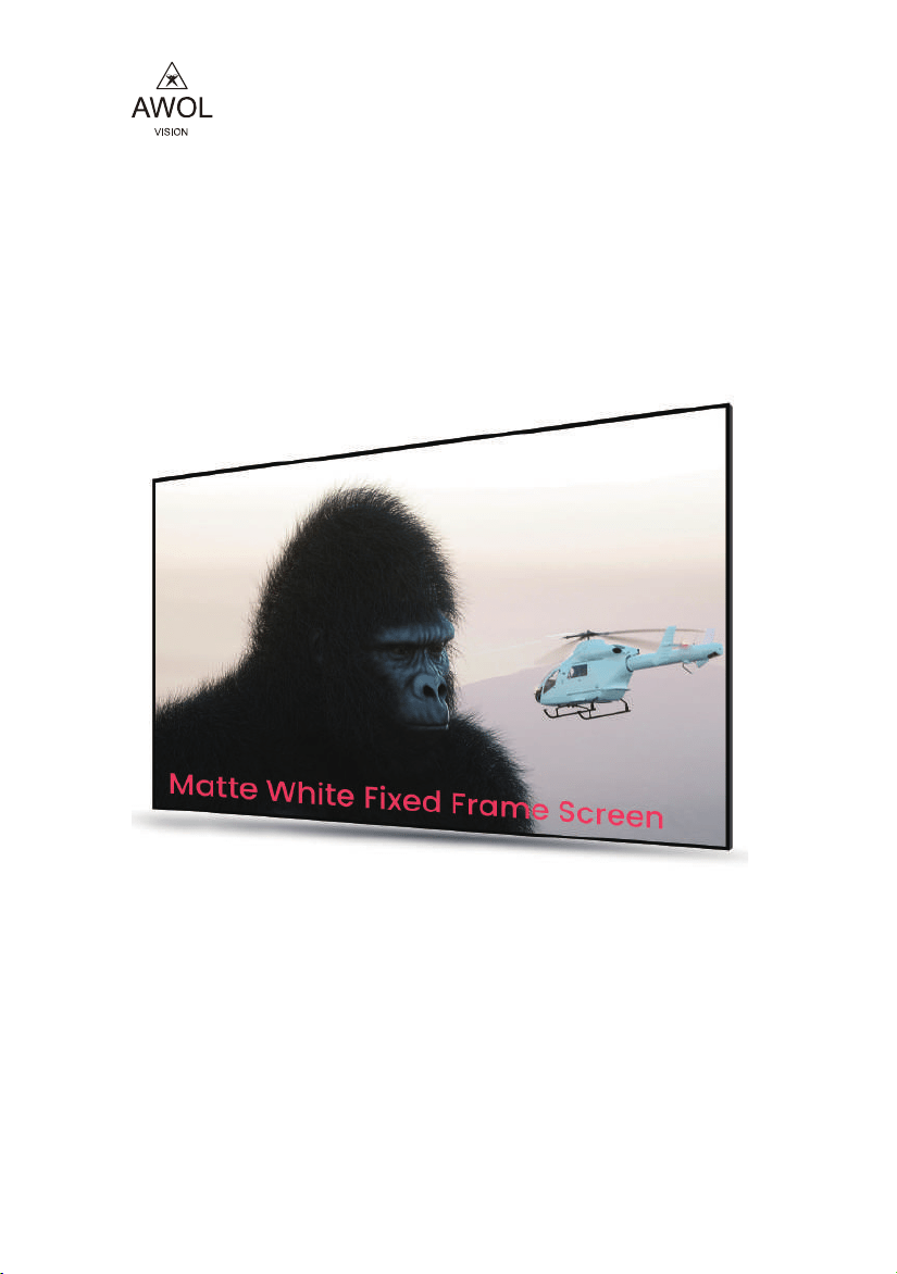
AWOL Vision Matte white
Fixed Frame Screen
INSTRUCTION MANUAL
Thank you for chossing the AWOL Vision Matte
White Projection Screen. Please read this manual
carefully before installtion and use.
www.awolvision.com
support@awolvision.com
- 11 -
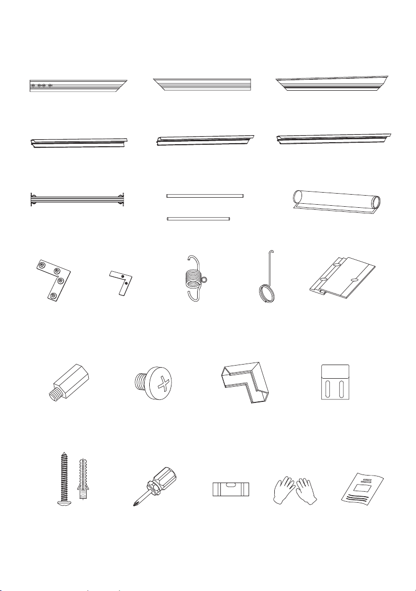
PACKING LIST
○
1
×Inner frame A 2
○
2
×
Outer frame A 2
○
3
×
Support rod 1
○
5
×
Screnn
1
○
6
Corner
connectors
×4
M5 single head
hexagon stud
×4
M5*6
Phillips screw
×6
Corner
protection ×4
Wall bracket
×2
Wall bracket
screw
×4 set
Phillips
screwdriver
×1
Spirit level
×1 Gloves
×1
Manual
×1
○
7
○
9
○
10
○
11
○
12
○
14
○
15
○
13
○
8
Corner
connectors
×4
Tension
spring
×N
Pull hook
×1
Outer frame
connector
×2
○
2
×
Outer frame B 2
○
4
×
Glass fiber strip
2
○
4
×
Glass fiber strip
4
○
2
×
Outer frame C 2
○
1
×Inner frame B 2
○
1
×Inner frame C 2
7.0 Specification
- 2 -
AWOL Vision Matte White Screen Specification
Model
Size
Material
Gain
Resolution
Viewing Angle
Projection Ratio
Matched Projector
MW-100
MW-120
100 inch
120 inch
Matte white Matte white
1.3 dB
1.3 dB
up to 8K up to 8K
170°
170°
16:9
16:9
Long Throw Projector
Shor Throw Projector
Ultra Short Throw Projector
Long Throw Projector
Shor Throw Projector
Ultra Short Throw Projector
Screen Weight
Package Size
Package Weight
1405*230*130MM
55.3*9.1*5.2 inch
17.2 lbs / 7.8 kg
25.41 lbs / 11.5 kg
1650*230*130MM
65.0*9.1*5.1 inch
28.7 lbs / 13 kg
21.4 lbs / 9.7 kg

- 11 -
- 10 - - 3 -
1 -A
1 -B
1 -C
1 -C
6
5
6
6
Figure 1
Figure 2
3
The slider nut has been fixed in
the inner frame A, which can be
used to fix the support rod
14
1
Hang the inner
frame slot on
the wall bracket
Figure 13
Figure 14
6.3 Hang the assembled screen on the wall (operated by two persons) (Figure 14)
14
14
15
15
6.2 Drill holes on the marks on the wall with a percussion drill, insert the rubber plug, screw on the screws,
and fix the wall bracket (Figure 13)
1.0 Precautions
2.0 Assemble the frame
To ensure the projection performance of this product, please pay attention to the following operating
requirements.
1.1 When assembling, find a suitable size floor or table. The surface must be clean and free of any obstacles.
The floor or table must be covered with clean materials such as cloth, film, blankets, etc.
1.2 Handle with care during installation to prevent personal
injury or property damage.
1.3 Do not touch the surface of the projection screen
with unglved hands.
1.4 Do not touch the projection surface with sharp or hard
objects to prevent damage to the screen material.
1.5 Keep children away from the screen to prevent accidents.
1.6 The surface of the screen must be cleaned and treated regularly, and it is
recommended to take care of it once every two weeks.
1.7 Please use a soft cotton cloth to wipe (dip some water) gently, and it is not advisable to
use any chemical cleaners or alcohol.
2.1 Open the package and check whether the accessories in the box are complete.
2.2 Connect inner frame A and inner frame B first (Figure 1)
2.3 Insert the 4 corner connectors into the inner frame C (picture 2)
2.4 Assemble the four inner frames and struts as shown in the figure below, and lock them with screws
after the inner frame is assembled (Figure 2, Figure 3);
○
○
○
○

- 4 - - 9 -
Figure 3
5
Figure 4
Figure 12
Screen projection face down
Black side up
Cloth liner
Notice:
Be careful to avoid
scratching the screen
105mm
"H"-105mm
14
14
Screen
Wall
1.6M
Mark with a marker
The screen is 50cm~80cm away from the ground
Ground
Wall
6.0 Mount on the wall
3.0 Assemble the screen
3.1 Wear gloves (to avoid the screen being stained with fingerprints that can not be erased).
Lay a clean cloth on a flat, clean surface (or ground) to protect the screen.
3.2 Take out the screen from the package, turn the screen face down, unfold the screen, and
then according to the length of the glass fiber strips, take the glass fiber strips insert to around
of screen as shown below.
6.1 Install wall hangers on the wall according to screen size. Required tools: level, hammer drill, pencil,
ladder, etc. As shown below. Please estimate the installation position of the screen before installing
the wall pendants. The height of the lower edge of the screen from the ground is generally
about 50~80cm.
Total screen height

- 8 - - 5 -
4 -A
4 -A
4 -B
4 -B4 -B
4 -B
Figure 6
2 -C
2 -C
2 -A
2 -B
2 -A
2 -B
7
7
7
7
12
12
13
Figure 10
Figure 11
Figure 5
5.2 Put the outer frame against the frame screen, align the four corners, connect the surroundings with
corner connector and lock all the screws (Figure 10)
5.3 Use screws to lock the joints of the outer frame on the hexagonal studs, and clip the corner protectors
into the slots of the outer frame (Figure 11)
4.1 Put the assembled frame on the screen. Align the frame with the line marks on the four corners
of the screen (Figure 6)
Important note: Please cooperate with two people when assembling, and do not
make any actions that may cause the screen to fold or rub against hard objects.
○
○
○
○
○
○
○
○
○
○
4.0 Assemble screen and inner frame
- 6 - - 7 -
4
4
8
5
8
1
2
3
4
5
6
7
8
9
10
11
12
Figure 7
Figure 9
11
9
2 -A
2 -B
12
12
10
2 -A
2 -B
10
12
12
Figure 8
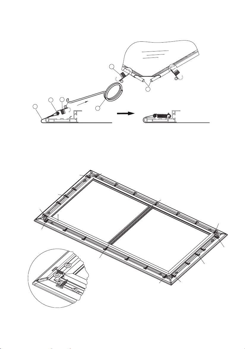
4.2 Adjust the position of the screen and the frame so that the frame is in the middle of the screen, and
check the overall flatness of the screen. before installing the tension spring.
5.1 Splice the outer frame A and outer frame B into a complete frame (Figure 8), and drive the hexagonal
studs into the long frame splicing strip (Figure 9)
4.3 Hang the screen on the frame with the tension spring. Please follow the following sequence for
hooking tension springs, Firstly install the four corner springs in the order of 1~8; then hang the middle
springs 9~12, and finally spring from the middle, and install the other springs symmetrically in turn (Figure 7)
5.0 Outer frame installation

- 6 - - 7 -
4
4
8
5
8
1
2
3
4
5
6
7
8
9
10
11
12
Figure 7
Figure 9
11
9
2 -A
2 -B
12
12
10
2 -A
2 -B
10
12
12
Figure 8
4.2 Adjust the position of the screen and the frame so that the frame is in the middle of the screen, and
check the overall flatness of the screen. before installing the tension spring.
5.1 Splice the outer frame A and outer frame B into a complete frame (Figure 8), and drive the hexagonal
studs into the long frame splicing strip (Figure 9)
4.3 Hang the screen on the frame with the tension spring. Please follow the following sequence for
hooking tension springs, Firstly install the four corner springs in the order of 1~8; then hang the middle
springs 9~12, and finally spring from the middle, and install the other springs symmetrically in turn (Figure 7)
5.0 Outer frame installation

- 8 - - 5 -
4 -A
4 -A
4 -B
4 -B4 -B
4 -B
Figure 6
2 -C
2 -C
2 -A
2 -B
2 -A
2 -B
7
7
7
7
12
12
13
Figure 10
Figure 11
Figure 5
5.2 Put the outer frame against the frame screen, align the four corners, connect the surroundings with
corner connector and lock all the screws (Figure 10)
5.3 Use screws to lock the joints of the outer frame on the hexagonal studs, and clip the corner protectors
into the slots of the outer frame (Figure 11)
4.1 Put the assembled frame on the screen. Align the frame with the line marks on the four corners
of the screen (Figure 6)
Important note: Please cooperate with two people when assembling, and do not
make any actions that may cause the screen to fold or rub against hard objects.
○
○
○
○
○
○
○
○
○
○
4.0 Assemble screen and inner frame

- 4 - - 9 -
Figure 3
5
Figure 4
Figure 12
Screen projection face down
Black side up
Cloth liner
Notice:
Be careful to avoid
scratching the screen
105mm
"H"-105mm
14
14
Screen
Wall
1.6M
Mark with a marker
The screen is 50cm~80cm away from the ground
Ground
Wall
6.0 Mount on the wall
3.0 Assemble the screen
3.1 Wear gloves (to avoid the screen being stained with fingerprints that can not be erased).
Lay a clean cloth on a flat, clean surface (or ground) to protect the screen.
3.2 Take out the screen from the package, turn the screen face down, unfold the screen, and
then according to the length of the glass fiber strips, take the glass fiber strips insert to around
of screen as shown below.
6.1 Install wall hangers on the wall according to screen size. Required tools: level, hammer drill, pencil,
ladder, etc. As shown below. Please estimate the installation position of the screen before installing
the wall pendants. The height of the lower edge of the screen from the ground is generally
about 50~80cm.
Total screen height

- 11 -
- 10 - - 3 -
1 -A
1 -B
1 -C
1 -C
6
5
6
6
Figure 1
Figure 2
3
The slider nut has been fixed in
the inner frame A, which can be
used to fix the support rod
14
1
Hang the inner
frame slot on
the wall bracket
Figure 13
Figure 14
6.3 Hang the assembled screen on the wall (operated by two persons) (Figure 14)
14
14
15
15
6.2 Drill holes on the marks on the wall with a percussion drill, insert the rubber plug, screw on the screws,
and fix the wall bracket (Figure 13)
1.0 Precautions
2.0 Assemble the frame
To ensure the projection performance of this product, please pay attention to the following operating
requirements.
1.1 When assembling, find a suitable size floor or table. The surface must be clean and free of any obstacles.
The floor or table must be covered with clean materials such as cloth, film, blankets, etc.
1.2 Handle with care during installation to prevent personal
injury or property damage.
1.3 Do not touch the surface of the projection screen
with unglved hands.
1.4 Do not touch the projection surface with sharp or hard
objects to prevent damage to the screen material.
1.5 Keep children away from the screen to prevent accidents.
1.6 The surface of the screen must be cleaned and treated regularly, and it is
recommended to take care of it once every two weeks.
1.7 Please use a soft cotton cloth to wipe (dip some water) gently, and it is not advisable to
use any chemical cleaners or alcohol.
2.1 Open the package and check whether the accessories in the box are complete.
2.2 Connect inner frame A and inner frame B first (Figure 1)
2.3 Insert the 4 corner connectors into the inner frame C (picture 2)
2.4 Assemble the four inner frames and struts as shown in the figure below, and lock them with screws
after the inner frame is assembled (Figure 2, Figure 3);
○
○
○
○
- 11 -
PACKING LIST
○
1
×Inner frame A 2
○
2
×
Outer frame A 2
○
3
×
Support rod 1
○
5
×
Screnn
1
○
6
Corner
connectors
×4
M5 single head
hexagon stud
×4
M5*6
Phillips screw
×6
Corner
protection ×4
Wall bracket
×2
Wall bracket
screw
×4 set
Phillips
screwdriver
×1
Spirit level
×1 Gloves
×1
Manual
×1
○
7
○
9
○
10
○
11
○
12
○
14
○
15
○
13
○
8
Corner
connectors
×4
Tension
spring
×N
Pull hook
×1
Outer frame
connector
×2
○
2
×
Outer frame B 2
○
4
×
Glass fiber strip
2
○
4
×
Glass fiber strip
4
○
2
×
Outer frame C 2
○
1
×Inner frame B 2
○
1
×Inner frame C 2
7.0 Specification
- 2 -
AWOL Vision Matte White Screen Specification
Model
Size
Material
Gain
Resolution
Viewing Angle
Projection Ratio
Matched Projector
MW-100
MW-120
100 inch
120 inch
Matte white Matte white
1.3 dB
1.3 dB
up to 8K up to 8K
170°
170°
16:9
16:9
Long Throw Projector
Shor Throw Projector
Ultra Short Throw Projector
Long Throw Projector
Shor Throw Projector
Ultra Short Throw Projector
Screen Weight
Package Size
Package Weight
1405*230*130MM
55.3*9.1*5.2 inch
17.2 lbs / 7.8 kg
25.41 lbs / 11.5 kg
1650*230*130MM
65.0*9.1*5.1 inch
28.7 lbs / 13 kg
21.4 lbs / 9.7 kg

- 1 -
AWOL Vision Matte white
Fixed Frame Screen
INSTRUCTION MANUAL
Thank you for chossing the AWOL Vision Matte
White Projection Screen. Please read this manual
carefully before installtion and use.
www.awolvision.com
support@awolvision.com