
Installation/Operation
Topload Washers
Metered Commercial
TLW12C_SVG
Original Instructions
Keep These Instructions for Future Reference.
CAUTION: Read the instructions before using the machine.
(If this machine changes ownership, this manual must accompany machine.)
www.alliancelaundry.com
Part No. 205161EN
October 2020


WARNING
Failure to install, maintain, and/or operate this ma-
chine according to the manufacturer's instructions
may result in conditions which can produce bodily
injury and/or property damage.
W030
WARNING
For your safety and to reduce the risk of fire or an
explosion, do not store or use gasoline or other
flammable vapors and liquids in the vicinity of this or
any other appliance.
W022
NOTE: The WARNING and IMPORTANT instructions ap-
pearing in this manual are not meant to cover all possi-
ble conditions and situations that may occur. It must
be understood that common sense, caution, and care-
fulness are factors which cannot be built into these
washers. These factors MUST BE supplied by the per-
son(s) installing, maintaining, or operating the unit.
Always contact the distributor, service agent, or the manufacturer
about any problems or conditions you do not understand.
Read all instructions before using unit.
This product uses FreeRTOS V7.2.0 (www.freertos.org).
©
Copyright, Alliance Laundry Systems LLC -
DO NOT COPY or TRANSMIT
3 Part No. 205161EN
Regulatory Statements
PRODUCT COMPLIANCE
Users of this product are cautioned not to make modifications or
changes that are not approved by Alliance Laundry Systems,
LLC. Doing so may void the compliance of this product with ap-
plicable laws and regulatory requirements and may result in the
loss of the user’s authority to operate the equipment.
UNITED STATES
This device complies with Part 15 of the FCC Rules. Operation is
subject to the following two conditions; (1) This device may not
cause harmful interference, and (2) this device must accept any
interference received, including interference that may cause un-
desired operation.
This equipment has been tested and found to comply with the
limits for a Class B digital device, pursuant to Part 15 of the FCC
Rules. These limits are designed to provide reasonable protection
against harmful interference in a residential installation. This
equipment generates uses and can radiate radio frequency energy
and, if not installed and used in accordance with the instructions,
may cause harmful interference to radio communications. How-
ever, there is no guarantee that interference will not occur in a
particular installation. If this equipment does cause harmful inter-
ference to radio or television reception, which can be determined
by turning the equipment off and on, the user is encouraged to try
to correct the interference by one or more of the following meas-
ures:
• Reorient or relocate the radio or television receiving antenna.
• Increase the separation between the computer equipment or
receiver.
• Connect the equipment into an outlet on a circuit different
from that to which the radio or television receiver is connec-
ted.
• Consult the dealer or experienced radio television technician
for help.
CAUTION
To comply with the limits of the Class B device, pur-
suant to Part 15 of the FCC Rules, this device is to
comply with Class B limits. All peripherals must be
shielded and grounded. Operation with non-certified
peripherals or non-shielded cables is likely to result
in interference and reception of the device.
W1004
Radiation Exposure Statement: This equipment complies with
FCC radiation exposure limits set forth for an uncontrolled envi-
ronment. The radio installed in this equipment and is intended to
operate with minimum distance 20cm between the radiator and
your body.
Limited Channels Fixed For Use In USA: IEEE 802.11b or
802.11g or 802.11n(HT20) operation of this product in the U.S. is
firmware-limited to Channel 1 through 11.
CANADA - CAN ICES-3(B)/NMB-3(B)
This device contains license-exempt transmitter(s)/receiver(s)
that comply with Innovation, Science and Economic Develop-
ment Canada’s license-exempt RSS(s) standards. Operation is
subject to the following two conditions:
• This device may not cause interference.
• This device must accept any interference, including interfer-
ence that may cause undesired operation of the device.
Radiation Exposure Statement: This equipment complies with
Innovation, Science and Economic Development Canada’s radia-
tion exposure limits set forth for in RSS-102. The radio installed
in this equipment is installed and is intended to operate with min-
imum distance 20cm between the radiator and your body.
EUROPE
Products bearing the CE mark comply with the following EU di-
rectives:
• EMC Directive 2014/30/EU
• Low Voltage Directive 2014/35/EU
• Ecodesign Directive 2009/125/EC
• RoHS Directive 2011/65/EU and its amendment directives;
Commission Delegated Directive 2015/863 to restrict four
phthalates
• REACH Regulation 1907/2006 and its amendment regula-
tions
• POP Regulation 850/2004 and its amendment regulations
If the product has telecommunications functionality, it also com-
plies with the requirements of the following EU directive:
• Radio Equipment Directive 2014/53/EU
Compliance with these Directives implies conformity to harmon-
ized European standards that are noted in the EU Declaration of
Conformity which is available upon request.
Alliance Laundry Systems products comply with the requirement
of Article 12 as it can be operated in at least one Member State as
examined and the product is compliant with Article 11 as it has
no restrictions on putting into service in all EU member states.
This device contains a 2.4GHz transceiver, intended for indoor
use only in all EU member states, EFTA states, and Switzerland.
Attention has been given to allowed operational frequencies. For
detailed information concerning installations in France, the user
should contact the national spectrum authority in France (http://
www.arcep.fr/ )
Be aware that outdoor installations require special attention and
will only be handled by trained and qualified installation person-
Regulatory Statements
©
Copyright, Alliance Laundry Systems LLC -
DO NOT COPY or TRANSMIT
4 Part No. 205161EN

nel. No one from the general-public is permitted to install wire-
less products outdoors when external antennas, power and
grounding must be installed for use.
AUSTRALIA/NEW ZEALAND
The radio in this equipment complies with and is certified to the
Australian and New Zealand regulatory requirements.
BRAZIL ANATEL
This device is not entitled to protection against harmful interfer-
ence and may not interfere with duly authorized systems.
CHINA SRRC
The radio device has recieved certification of conformance in ac-
cordance with the People's Republic of China State Radio Regu-
lation Committee (SRRC) certification scheme. Integrations of
this radio into a final product does not require additional radio
certification provided installation instructions are followed. No
changes are authorized to the radio or the antenna of the ap-
proved device.
JAPAN
This product is equipped with a certified wireless device pursuant
to Article 2-1-19 of the Certification Ordinance. No changes are
authorized to the radio or the antenna of the approved device.
MEXICO IFETEL
“The operation of this equipment is subject to the following two
conditions: (1) it is possible that this equipment or device does
not cause harmful interference and (2) this equipment or device
must accept any interference, including that which may cause its
unwanted operation.”
SOUTH KOREA (KC)
The radio device has received certification of conformance in ac-
cordance with the Radio Waves Act. Integration of this radio into
a final product does not require additional radio certification pro-
vided installation instructions are followed. No changes are au-
thorized to the radio or the antenna of the approved device.
TAIWAN
The information in this section applies to products bearing the
Taiwan National Communications Commission mark:
This telecom equipment has complied with NCC regulations.
According to “Administrative Regulations of Low Power Radio
Waves Radiated Devices:
Article 12 The low-power radio-frequency devices must not be
altered by changing the frequency, enhancing emission power,
adding external antenna, and modification of original design
characteristic as well as function.
Article 14 The operation of the low-power radio-frequency devi-
ces is subject to the conditions that no harmful interference is
caused. The user must stop operating the device immediately
should harmful interference is caused and shall not resume until
the condition causing the harmful interference has been correc-
ted.
Moreover, the interference must be accepted that may be caused
by the operation of an authorized communications, or ISM equip-
ment. (1) Precautions (marked in the product manual and on out-
er packaging)
THAILAND
The information in this section applies to products approved by
the Thailand National Communications Commission:
These telecommunication and device are compliance with the re-
quirements of National Broadcasting and Telecommunication
Commission.
Regulatory Statements
©
Copyright, Alliance Laundry Systems LLC -
DO NOT COPY or TRANSMIT
5 Part No. 205161EN
Safety Information
Explanation of Safety Messages
Precautionary statements (“DANGER,” “WARNING,” and
“CAUTION”), followed by specific instructions, are found in this
manual and on machine decals. These precautions are intended
for the personal safety of the operator, user, servicer, and those
maintaining the machine.
DANGER
Indicates an imminently hazardous situation that, if
not avoided, will cause severe personal injury or
death.
WARNING
Indicates a hazardous situation that, if not avoided,
could cause severe personal injury or death.
CAUTION
Indicates a hazardous situation that, if not avoided,
may cause minor or moderate personal injury or
property damage.
Additional precautionary statements (“IMPORTANT” and
“NOTE”) are followed by specific instructions.
IMPORTANT: The word “IMPORTANT” is used to in-
form the reader of specific procedures where minor
machine damage will occur if the procedure is not fol-
lowed.
NOTE: The word “NOTE” is used to communicate in-
stallation, operation, maintenance or servicing informa-
tion that is important but not hazard related.
Important Safety Instructions
Save These Instructions
WARNING
To reduce the risk of fire, electric shock, serious in-
jury or death to persons when using your washer,
follow these basic precautions:
W023
• Read all instructions before using the washer.
• Install the washer according to the INSTALLATION IN-
STRUCTIONS. Refer to the EARTH/GROUND INSTRUC-
TIONS in the INSTALLATION manual for the proper earth/
ground connection of the washer. All connections for water,
drain, electrical power and earth/ground must comply with lo-
cal codes and be made by licensed personnel when required.
Do not do it yourself.
• Do not install or store the washer where it will be exposed to
water and/or weather.
• Do not wash articles that have been previously cleaned in,
washed in, soaked in, or spotted with gasoline, dry-cleaning
solvents, or other flammable or explosive substances as they
give off vapors that could ignite or explode.
• Do not add the following substances or textiles containing
traces of the following substances to the wash water: gasoline,
kerosene, waxes, cooking oils, vegetable oils, machine oils,
dry-cleaning solvents, flammable chemicals, thinners or other
flammable or explosive substances. These substances give off
vapors that could ignite, explode or cause the fabric to catch
on fire by itself.
• Under certain conditions, hydrogen gas may be produced in a
hot water system that has not been used for two weeks or
more. HYDROGEN GAS IS EXPLOSIVE. If the hot water
system has not been used for such a period, before using a
washing machine or combination washer-dryer, turn on all hot
water faucets and let the water flow from each for several mi-
nutes. This will release any accumulated hydrogen gas. THE
GAS IS FLAMMABLE, DO NOT SMOKE OR USE AN
OPEN FLAME DURING THIS TIME.
• To reduce the risk of an electric shock or fire, DO NOT use an
extension cord or an adapter to connect the washer to the elec-
trical power source.
• Do not allow children to play on or in the washer. Close su-
pervision of children is necessary when the washer is used
near children. This appliance is not intended for use by per-
sons (including children) with reduced physical, sensory or
mental capabilities, or lack of experience and knowledge, un-
less they have been given supervision or instruction concern-
ing the use of the appliance by a person responsible for their
safety. This is a safety rule for all appliances.
• Cleaning and user maintenance shall not be made by children
without supervision.
Safety Information
©
Copyright, Alliance Laundry Systems LLC -
DO NOT COPY or TRANSMIT
6 Part No. 205161EN

• Children less than three years should be kept away unless
continuously supervised.
• Do not reach into the washer if the washtub or agitator, if ap-
plicable, is moving.
• Never operate the washer with any guards, panels and/or parts
removed or broken. DO NOT tamper with the controls or by-
pass any safety devices.
• Use your washer only for its intended purpose, washing
clothes. Always follow the fabric care instructions supplied
by the garment manufacturer.
• Always read and follow manufacturer’s instructions on pack-
ages of laundry and cleaning aids. To reduce the risk of poi-
soning or chemical burns, keep them out of the reach of chil-
dren at all times (preferably in a locked cabinet). Heed all
warnings or precautions.
• Do not use fabric softeners or products to eliminate static un-
less recommended by the manufacturer of the fabric softener
or product.
• Lid MUST BE CLOSED any time the washer is to agitate or
spin. DO NOT bypass the lid switch to permit the washer to
agitate or spin with the lid open. A brake will stop the wash-
tub within seconds if the lid is opened during spinning. If the
washtub does not stop when the lid is opened, remove the
washer from use and call the service person.
• Be sure water connections have a shut-off valve and that fill
hose connections are tight. CLOSE the shut-off valves at the
end of each wash day.
• Keep your washer in good condition. Bumping or dropping
the washer can damage safety features. If this occurs, have
your washer checked by a qualified service person.
• Do not repair or replace any part of the washer, or attempt any
servicing unless specifically recommended in the user-mainte-
nance instructions or in published user-repair instructions that
you understand and have the skills to carry out. ALWAYS dis-
connect the washer from electrical supply before attempting
any service.
• Disconnect the power cord by grasping the plug, not the cord.
If the supply cord is damaged, it must be replaced by the man-
ufacturer, its service agent or similarly qualified persons in or-
der to avoid a hazard.
• Before the washer is removed from service or discarded, re-
move the lid or door to the washing compartment.
• Failure to install, maintain, and/or operate this washer accord-
ing to the manufacturer’s instructions may result in conditions
which can produce bodily injury and/or property damage.
NOTE: The WARNING and IMPORTANT SAFETY IN-
STRUCTIONS appearing in this manual are not meant
to cover all possible conditions and situations that may
occur. Observe and be aware of other labels and pre-
cautions that are located on the machine. They are in-
tended to provide instruction for safe use of the ma-
chine. Common sense, caution and care must be exer-
cised when installing, maintaining, or operating the
washer.
Always contact your dealer, distributor, service agent or the man-
ufacturer about any problems or conditions you do not under-
stand.
Safety Information
©
Copyright, Alliance Laundry Systems LLC -
DO NOT COPY or TRANSMIT
7 Part No. 205161EN

Table of Contents
Regulatory Statements........................................................................... 4
Safety Information................................................................................. 6
Explanation of Safety Messages....................................................................... 6
Important Safety Instructions........................................................................... 6
Model Identification..............................................................................10
Dimensions........................................................................................... 11
Installation........................................................................................... 12
Before You Start........................................................................................... 12
Tools........................................................................................................12
Order of Installation Steps..........................................................................12
Remove the Shipping Brace and Shipping Plug............................................... 12
Wipe Out Inside of Wash Tub.........................................................................13
Connect Fill Hoses........................................................................................13
Water Supply Requirements....................................................................... 14
Connecting Hoses......................................................................................14
Risers.......................................................................................................14
Connect Drain Hose to Drain Receptacle.........................................................15
Drain Facilities..........................................................................................15
High Standpipe Installation........................................................................ 15
Low Standpipe Installation.........................................................................16
Position and Level the Washer........................................................................16
Plug In the Washer........................................................................................ 17
Electrical Requirements............................................................................. 17
Earth/Ground Instructions.......................................................................... 18
Add Water to the Washer............................................................................... 18
Check Lid Switch......................................................................................... 18
Check Installation......................................................................................... 18
Vending....................................................................................................... 19
Meter Case............................................................................................... 19
Models Prepped for Card Reader................................................................ 19
Additional Security....................................................................................19
Operation............................................................................................. 21
Operation Instructions................................................................................... 21
Add Detergent...........................................................................................21
Load Laundry........................................................................................... 21
Close Lid..................................................................................................21
Set Cycle.................................................................................................. 21
©
Copyright 2020, Alliance Laundry Systems LLC
All rights reserved. No part of the contents of this book may be reproduced or transmitted in any form or by any means without the expressed
written consent of the publisher.
©
Copyright, Alliance Laundry Systems LLC -
DO NOT COPY or TRANSMIT
8 Part No. 205161EN

Set Wash Temperature............................................................................... 22
Select Wash Level..................................................................................... 22
Insert Coins or Card...................................................................................22
Start Washer..............................................................................................23
Indicator Lights.........................................................................................23
Maintenance......................................................................................... 24
User-Maintenance Instructions....................................................................... 24
Cold Weather Care.................................................................................... 24
Care of Your Washer..................................................................................24
Replacing Hoses........................................................................................24
Filter Screens............................................................................................ 24
Reinstallation of Shipping Materials............................................................... 24
Shipping Brace..........................................................................................24
Shipping Plug........................................................................................... 24
Motor Overload Protector.............................................................................. 24
Troubleshooting.................................................................................... 26
Contact Information............................................................................. 28
Installer Checklist.................................................................................29
©
Copyright, Alliance Laundry Systems LLC -
DO NOT COPY or TRANSMIT
9 Part No. 205161EN

Model Identification
Information in this manual is applicable to these washer models:
CTLW-35A
CTLW-36A
Model Identification
©
Copyright, Alliance Laundry Systems LLC -
DO NOT COPY or TRANSMIT
10 Part No. 205161EN
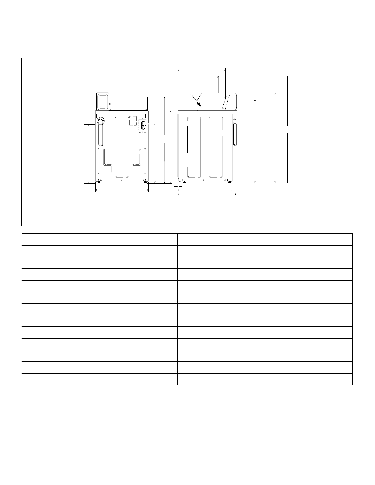
Dimensions
C
H
TLW2208N_SVG
L
K
J
I
H
G
F
E
D
C
B
1
A
1. Pilot Hole
A 22.44 in. [570 mm]
B 51 in. [1295 mm]
C - Standard Capacity Meter Case 43 in. [1092 mm]
C - High Capacity Meter Case 43.875 in. [1114 mm]
D 38.19 in. [970 mm]
E 28 in. [711 mm]
F 26 in. [660 mm]
G 0.44 in. [11 mm]
H 36 in. [914 mm]
I 41.25 in. [1048 mm]
J 28.75 in. [730 mm]
K 25.63 in. [651 mm]
L 30.5 in. [775 mm]
Dimensions
©
Copyright, Alliance Laundry Systems LLC -
DO NOT COPY or TRANSMIT
11 Part No. 205161EN
Installation
Before You Start
Tools
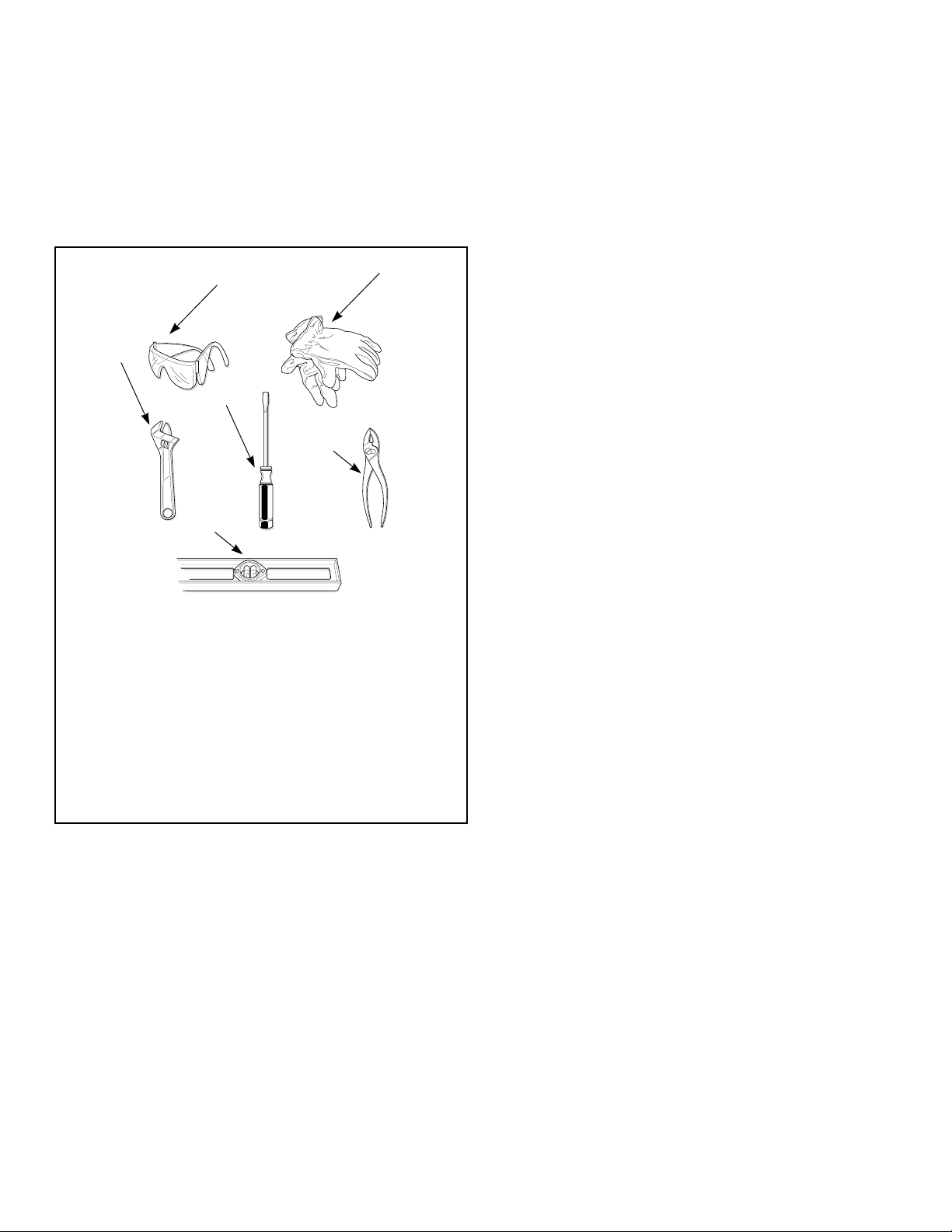
For most installations, the basic tools you will need are:
TLW2215N_SVG
1
2
3
4
5
6
NOTE: A cloth rag and all-purpose cleaner are also
needed.
1. Safety Glasses
2. Gloves
3. Wrench
4. Screwdriver
5. Pliers
6. Level
Figure 1
NOTE: If the washer is delivered on a cold day (below
freezing), or is stored in an unheated room or area dur-
ing the cold months, do not attempt to operate it until
the washer has had a chance to warm up.
NOTE: Install dryer before washer. This allows room for
attaching exhaust duct.
NOTE: This appliance is suitable for use in countries
having a warm, damp climate.
Order of Installation Steps
The proper order of steps must be followed to ensure correct in-
stallation. Refer to the list below when installing your unit.
1. Remove the shipping brace and shipping plug.
2. Wipe out inside of the washer.
3. Connect the fill hoses.
4. Connect the drain hose to the drain receptacle.
5. Position and level the washer.
6. Plug in the washer.
7. Add water to the washer.
8. Check the lid switch.
9. Check installation.
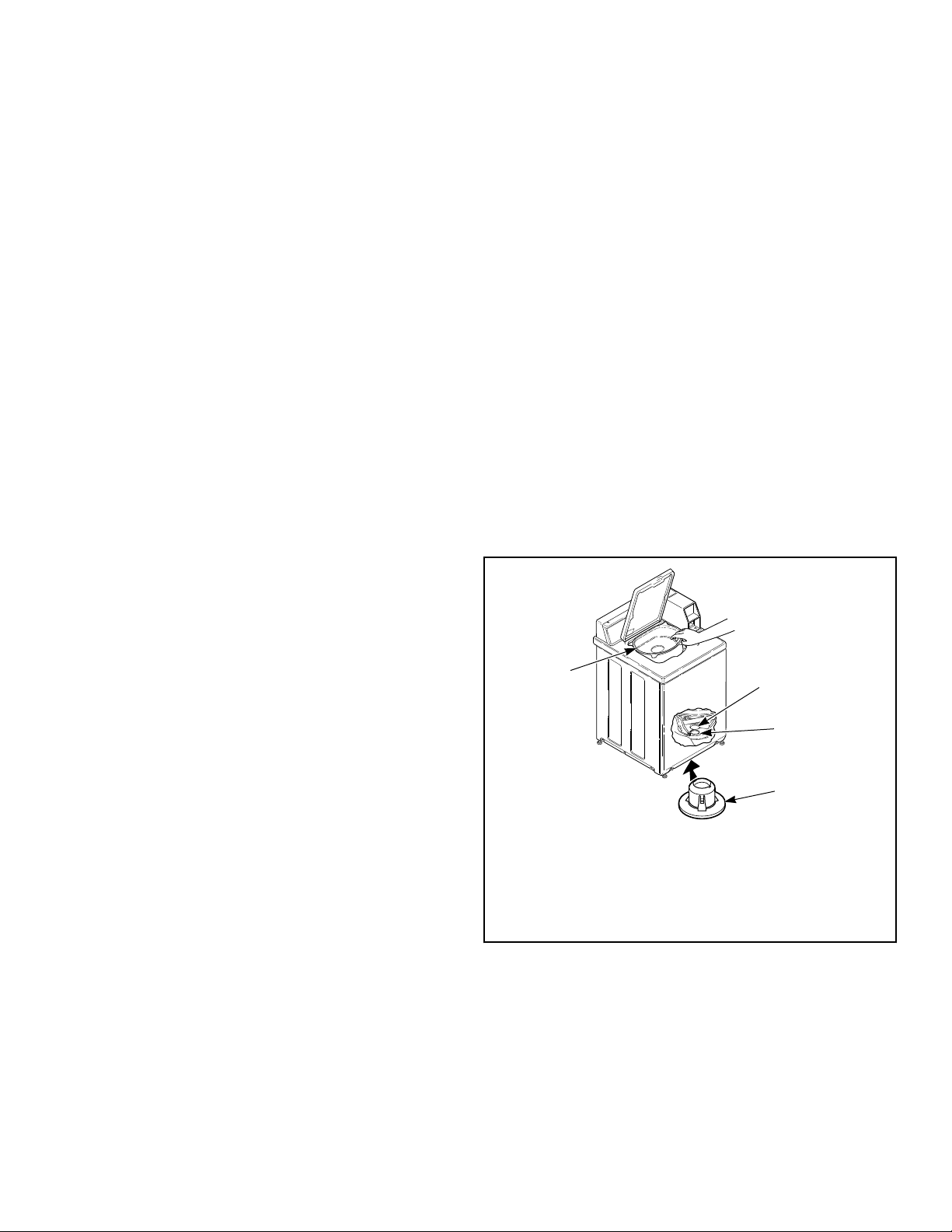
Remove the Shipping Brace and
Shipping Plug
1. Remove the shipping brace from under the lid.
2. The shipping plug will be released from the base of the wash-
er when removing the cardboard base from the washer.
The shipping brace and plug should be saved and must be rein-
stalled whenever washer is moved or transported to a new loca-
tion. This will prevent damage to washer components.
Do not tilt washer to front or sides when moving.
Refer to User-Maintenance section for instructions on reinstalling
shipping brace and shipping plug.
Installation
©
Copyright, Alliance Laundry Systems LLC -
DO NOT COPY or TRANSMIT
12 Part No. 205161EN
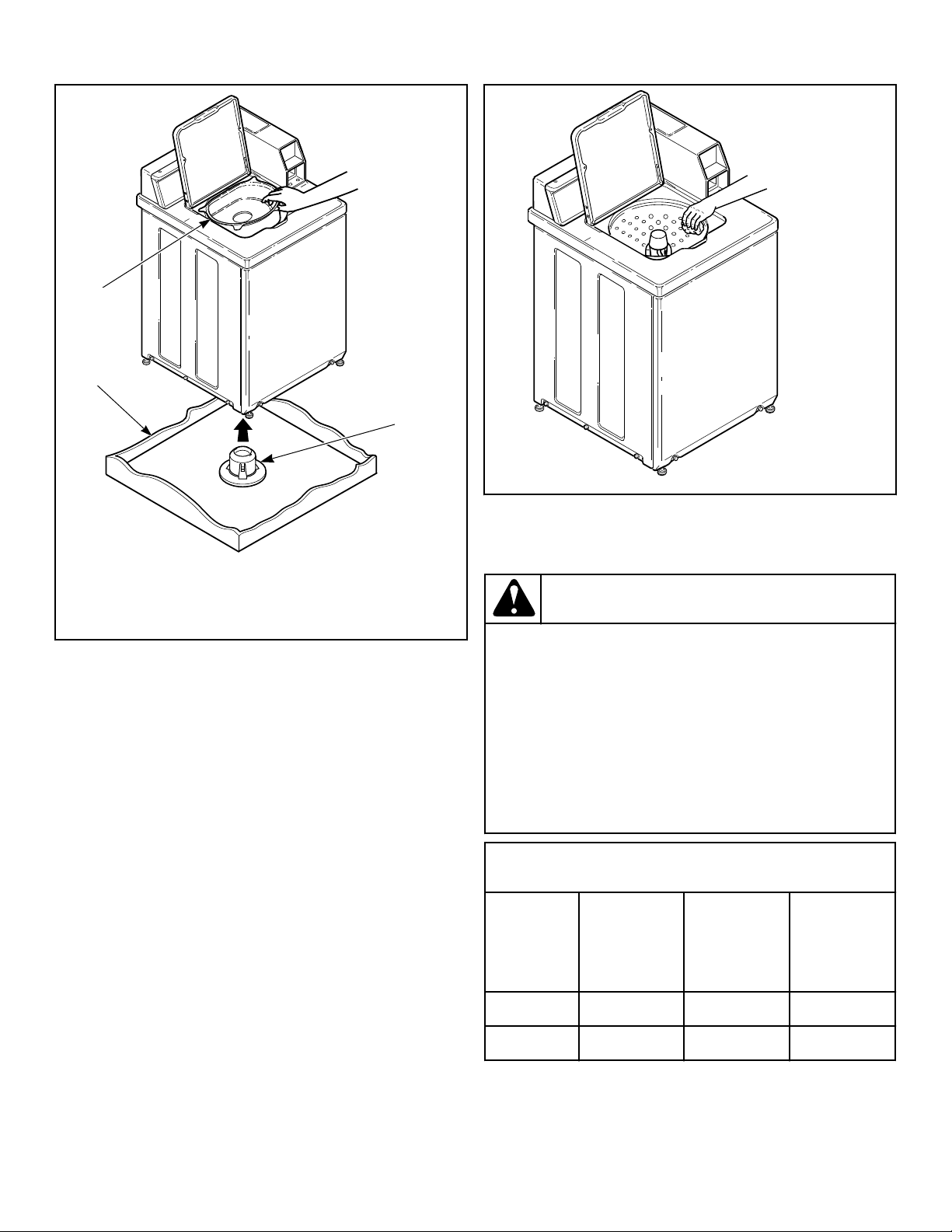
TLW2098N_svg
3
2
1
1. Shipping Brace
2. Shipping Plug
3. Cardboard Base
Figure 2
Wipe Out Inside of Wash Tub
Prior to first wash, use an all purpose cleaner or a detergent
and water solution and a damp cloth to remove shipping dust
from inside of the washer.
TLW2099N_SVG
Figure 3
Connect Fill Hoses
WARNING
Under certain conditions, hydrogen gas may be pro-
duced in a hot water system that has not been used
for two weeks or more. HYDROGEN GAS IS EXPLO-
SIVE. If the hot water system has not been used for
such a period and before using the washer, turn on
all hot water faucets and let the water flow from each
for several minutes. This will release any accumula-
ted hydrogen gas. The gas is flammable. Do not
smoke or use an open flame during this time.
W029
Mixing Valve Flow Rates
Pressure
psi [kPa]
HOT
gallons per
minute [liters
per minute]
COLD
gallons per
minute [liters
per minute]
WARM
gallons per
minute [liters
per minute]
20 [138] 3.4 [12.9] 3.4 [12.9] 4.0 [15.1]
120 [827] 4.6 [17.4] 4.6 [17.4] 4.6 [17.4]
Installation
©
Copyright, Alliance Laundry Systems LLC -
DO NOT COPY or TRANSMIT
13 Part No. 205161EN
Water Supply Requirements
Water supply faucets must fit standard 3/4 inch [19 mm] female
garden hose couplings. DO NOT USE SLIP-ON OR CLAMP-
ON CONNECTIONS.
NOTE: Water supply faucets should be readily accessi-
ble to permit turning them off when washer is not being
used.
Recommended cold water temperature is 50° to 75° Fahrenheit
[10° to 24° Celsius]. Recommended maximum hot water temper-
ature is 125° Fahrenheit [51° Celsius]. Warm water is a mixture
of hot and cold water. Warm water temperature is dependent upon
the water temperature and the pressure of both the hot and cold
water supply lines.
WARNING
To prevent personal injury, avoid contact with inlet
water temperatures higher than 125° Fahrenheit [51°
Celsius] and hot surfaces.
W748
Water pressure must be a minimum of 20 to a maximum of 120
pounds per square inch [minimum of 138 to a maximum of 827
kPa] static pressure measured at the faucet.
NOTE: Water pressure under 20 pounds per square
inch [138 kPa] will cause an extended fill time in the
washer and decreased rinse performance.
Turn on the water supply faucets and flush the lines for approxi-
mately two minutes to remove any foreign materials that could
clog the screens in the water mixing valve. This is especially im-
portant when installing your washer in a newly constructed or
renovated building. Build-up may have occurred during construc-
tion.
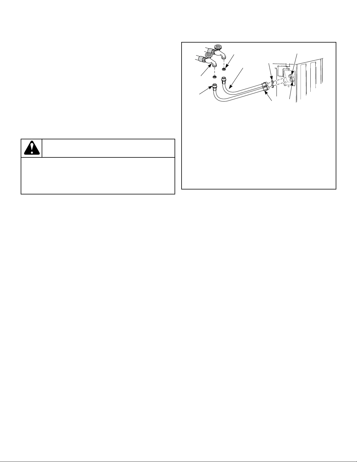
Connecting Hoses
1. Insert rubber washers and filter screens (from accessories
bag) in water fill hose couplings (two hoses supplied with
washer). The filter screen must be facing outward.
2. Connect fill hose couplings with filter screens to water supply
faucets.
3. Connect the other hose couplings to the hot and cold valve
connections at the rear of the washer.
4. Make sure the hose from the hot water faucet goes to the wa-
ter mixing valve marked “H” and the hose from the cold fau-
cet goes to the valve marked “C”.
5. Thread hose couplings onto valve connections finger tight.
Then turn 1/4 turn with pliers.
IMPORTANT: DO NOT cross thread or overtighten
couplings. This will cause them to leak.
6. Turn water on and check for leaks.
7. If leaks are found, retighten the hose couplings.
8. Continue tightening and rechecking until no leaks are found.
COLD
HOT
TLW2273N_SVG
C
H
8
7
6
5
4
3
2
1
1. Filter Screen (Screen must be facing outward)
2. Fill Hose
3. Plain Rubber Washer
4. Cold Water Connection
5. Hot Water Connection
6. Install this end of hose to valve connections at rear of
washer
7. Install this end of hose to water supply faucet
8. Faucet
Figure 4
IMPORTANT:
Hoses and other rubber parts deteriorate after exten-
ded use. Hoses may develop cracks, blisters or materi-
al wear from the temperature and constant high pres-
sure they are subjected to.
All hoses should be checked on a monthly basis for
any visible signs of deterioration. Any hose showing
the signs of deterioration listed above should be re-
placed immediately. All hoses should be replaced ev-
ery five years.
IMPORTANT: Turn off water supply faucets after check-
out and demonstration. Owner should turn off water
supply whenever there will be an extended period of
non-use.
Risers
Risers (or air cushions) may have to be installed if the pipes
knock or pound when flow of water stops. The risers are more ef-
ficient when installed as close as possible to the water supply fau-
cets. Refer to Figure 5 .
Installation
©
Copyright, Alliance Laundry Systems LLC -
DO NOT COPY or TRANSMIT
14 Part No. 205161EN
W005I_SVG
2
1
1. Risers (Air cushions)
2. Water Supply Faucets
Figure 5
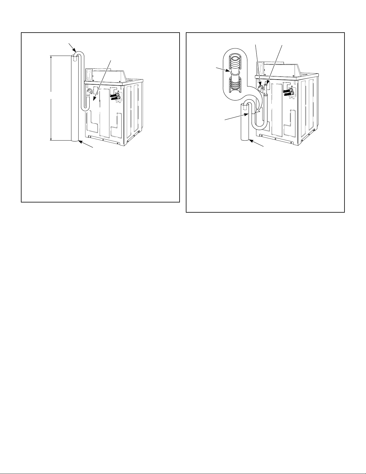
Connect Drain Hose to Drain
Receptacle
IMPORTANT: The drain hose installation is a very im-
portant factor in the washer installation. If care is not
taken when the drain hose is installed, a siphoning ac-
tion can be started which will cause water to be si-
phoned from the washer during the cycle.
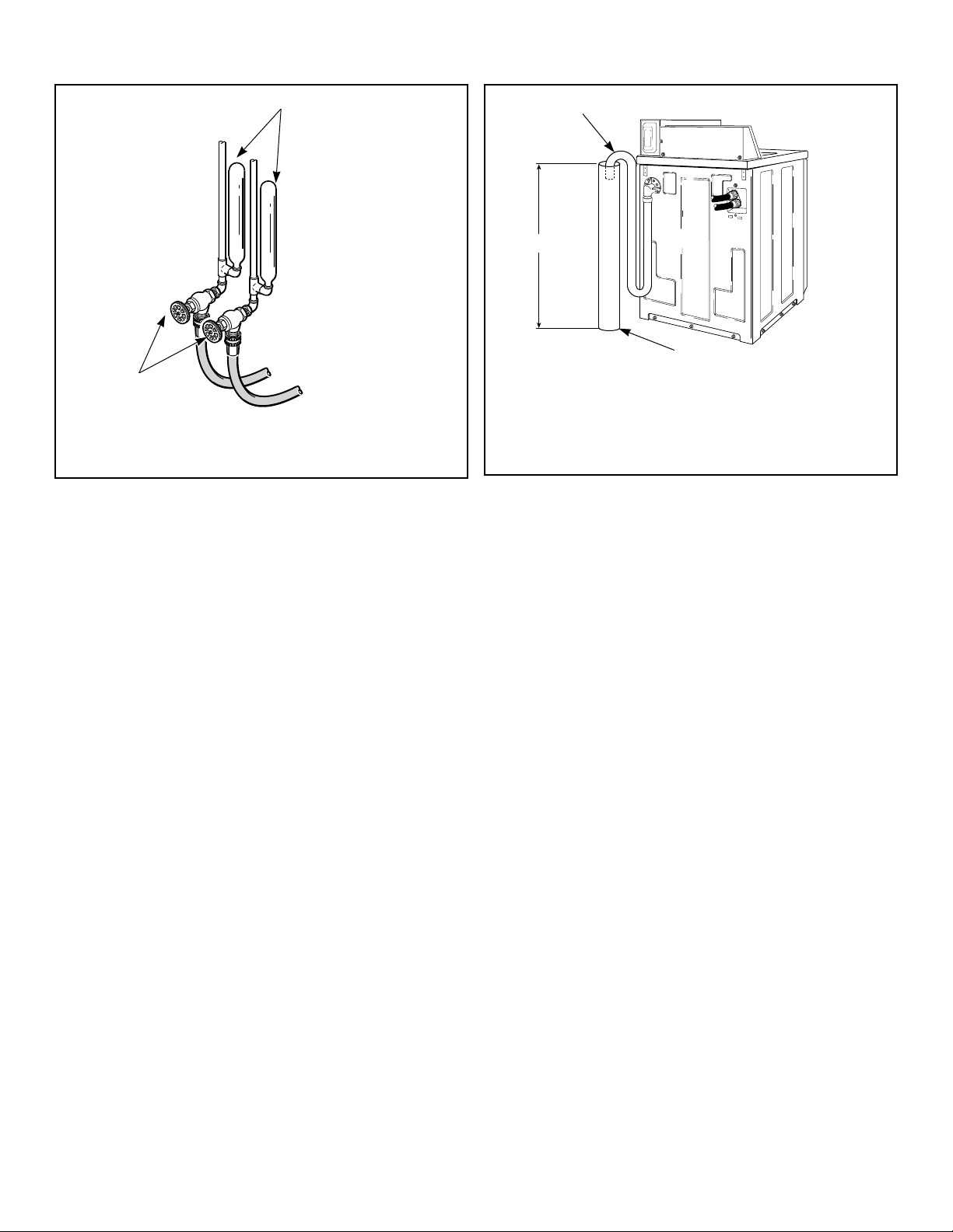
Drain Facilities
End of drain hose should never be in water as siphoning action
can be started that will cause water to be siphoned back into the
washer.
The curved end of drain hose MUST be installed even with or
above the height of the cabinet top of the washer to prevent si-
phoning. Refer to Figure 6 .
TLW2251N_SVG
3
2
1
1. Drain Hose
2. Standpipe
3. Recommended Standpipe Height 36 in. [914 mm] Mini-
mum
Figure 6
The standpipe or drain receptacle must be capable of handling a
minimum of 1-1/2 inches [38 mm] outside diameter drain hose.
The drain hose should fit loose within the standpipe (it should not
be snug fit). Never install the drain hose into a “sealed” drain sys-
tem as air cannot escape and will restrict the water from being
drained from the washer. A sealed drain system may also allow
water to be pumped back into the washer during agitation. Both
of these conditions may result in flooding of the washer.
Remove the drain hose from its shipping position on the rear of
the washer by unhooking the hose from the retainer clamp.
If necessary, follow the instructions for your type of drain recep-
tacle (high standpipe or low standpipe) to properly install the
drain hose.
High Standpipe Installation
NOTE: No. 562P3 Siphon Break Kit and No. 25863 Hose
Coupling are not required for this type of installation.
Installation
©
Copyright, Alliance Laundry Systems LLC -
DO NOT COPY or TRANSMIT
15 Part No. 205161EN
{
TLW2210N_SVG
4
3
2
1
1. Drain Hose
2. Cut Drain Hose off at This End to Fit the Washer Installa-
tion
3. Standpipe
4. Maximum Standpipe Height Not To Exceed 5 ft. [1.5 m]
Figure 7
IMPORTANT: Drain receptacle must be capable of han-
dling a minimum of 1-1/2 inch [38 mm] outside diame-
ter drain hose.
Low Standpipe Installation
If the drain facility is lower than the cabinet top, a siphon break
kit, Part No. 562P3, must be installed in the drain hose to prevent
siphoning action and drain hose MUST be cut to fit the washer
installation. Refer to Figure 8 . Use one No. 25863 Hose Cou-
pling to splice hose. The No. 562P3 Siphon Break Kit and No.
25863 Hose Coupling are available as optional equipment at ex-
tra cost through an authorized dealer or parts distributor. Installa-
tion instructions are supplied with the kit.
OPTIONAL: Raise the standpipe to the recommended height of
36 inches [914 mm].
IMPORTANT: Drain receptacle must be capable of han-
dling a minimum of 1-1/2 inch [38 mm] outside diame-
ter drain hose.
TLW2211N_SVG
{
3
2
1
5
4
1.
Drain Hose Elbow
2. 562P3 Siphon Break Kit
3. Standpipe
4. Cut Hose in This Area and Install No. 25863 Hose Cou-
pling
5. 25863 Hose Coupling
Figure 8
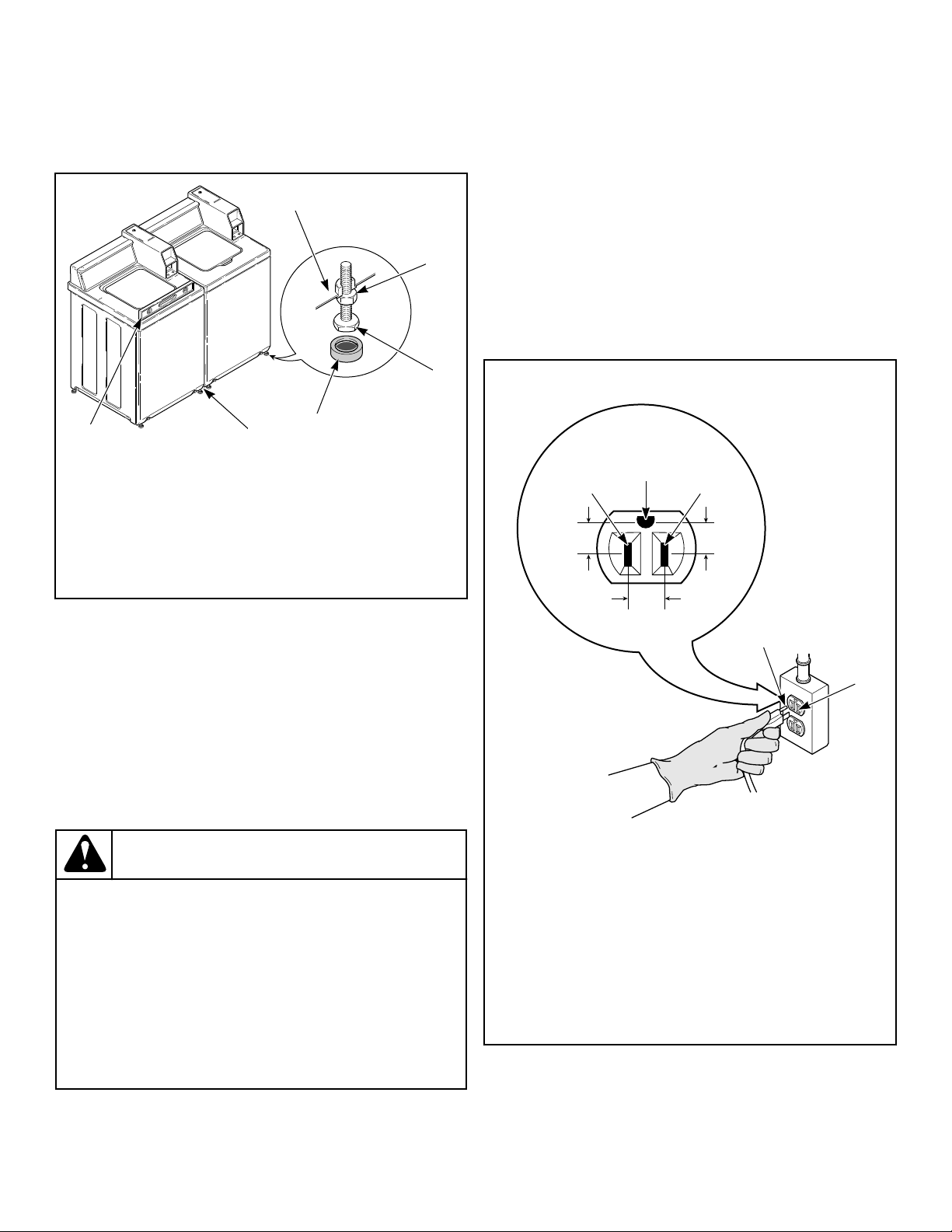
Position and Level the Washer
1. Position washer so it has sufficient clearance for installation
and servicing.
2. Place washer in position on a clean, dry, and reasonably firm
floor. Installing the washer on any type of carpeting is not rec-
ommended.
3. Place rubber cups (from accessories bag) on all four leveling
legs.
4. Place a level on the cabinet top and check if the washer is lev-
el from side to side and front to back.
5. If washer is not level, tilt washer back to access the front lev-
eling legs. Loosen the locknuts and adjust legs by screwing
into or out of washer base.
6. Once adjusted, tilt the washer forward on front legs and lower
back down into position to set the rear self-leveling legs.
7. Washer must not rock. When washer is level and does not
rock, tighten locknuts securely against bottom of washer base.
If these locknuts are not tight, washer will not remain station-
ary during operation.
Improper installation or flexing of weak floor will cause exces-
sive vibration.
Do not slide washer across floor once the leveling legs have been
extended, as legs and base could become damaged.
Installation
©
Copyright, Alliance Laundry Systems LLC -
DO NOT COPY or TRANSMIT
16 Part No. 205161EN
NOTE: For areas with uneven floors, a No. 566P3
Adjustable Rear Leg Extension Kit is available as
optional equipment at extra cost.
8. Verify that unit does not rock.
TLW2100N_SVG
6
5
4
3
2
1
1. Washer Base
2. Locknut
3. Leveling Leg
4. Rubber Cup
5. 1/2 inch [13 mm] Clearance Between Washers
6. Level
Figure 9
Plug In the Washer
Electrical Requirements
120 Volt, 60 Hertz with 3-Prong Earth/Ground Plug
NOTE: The wiring diagram is located in the control
hood.
NOTE: The wiring diagram is located in the control cab-
inet.
WARNING
To reduce the risk of fire, electric shock, serious in-
jury or death, all wiring and protective earth/ground
connections MUST conform with the latest edition of
the National Electrical Code, ANSI/NFPA No. 70, and
such local regulations as might apply. It is the cus-
tomer’s responsibility to have the wiring, fuses and
circuit breakers installed by a qualified electrician to
make sure adequate electrical power is available to
the washer.
W824
When plugging in the washer:
• DO NOT overload circuits.
• DO NOT use an extension cord.
• DO NOT use an adapter.
• DO NOT operate other appliances on the same circuit. Use
separately fused 15 Amp circuits.
The washer is designed to be operated on a separate branch, po-
larized, three-wire, effective earth/ground, 120 Volt, 60 Hertz,
AC (alternating current), circuit protected by a 15 ampere fuse,
equivalent fusetron or circuit breaker.
The three-prong earth/ground plug on the power cord should be
plugged directly into a polarized three-slot effective earth/ground
receptacle rated 110/120 Volts AC (alternating current) 15 Amps.
Refer to Figure 10 to determine correct polarity of the wall recep-
tacle.
Standard 120 Volt, 60 Hertz 3-Wire Effective Earth/
Ground Circuit
TLW2287N_SVG
6
8
7
2
1 3
5
4
1. L1
2. Earth/Ground
3. Neutral Side
4. Round Earth/Ground Prong
5. Neutral
6. 0 V.A.C.
7. 120 ± 12 V.A.C.
8. 120 ± 12 V.A.C.
Figure 10
Installation
©
Copyright, Alliance Laundry Systems LLC -
DO NOT COPY or TRANSMIT
17 Part No. 205161EN
WARNING
To reduce the risk of an electric shock or fire, DO
NOT use an extension cord or an adapter to connect
the washer to the electric power source.
W082
Earth/Ground Instructions
This appliance must be properly connected to protective earth/
ground. In the event of malfunction or breakdown, the earth/
ground will reduce the risk of electric shock by providing a path
of least resistance for electric current.
The appliance is equipped with a cord having an equipment earth/
ground conductor and a three-prong earth/ground plug. The plug
must be plugged into an appropriate outlet that is properly instal-
led and connected to a protective earth/ground in accordance with
all local codes and ordinances.
WARNING
Improper connection of the equipment earth/ground
conductor can result in a risk of electric shock.
Check with a qualified electrician or service person if
you are in doubt as to whether the unit is properly
connected to a protective earth/ground.
W893
• DO NOT modify the plug provided with the unit – if it will
not fit the outlet, have a proper outlet installed by a qualified
electrician.
• If the laundry room’s electrical supply does not meet the
above specifications and/or if you are not sure the laundry
room has an effective earth/ground, have a qualified electri-
cian or your local electrical utility company check it and cor-
rect any problems.
WARNING
Any disassembly requiring the use of tools must be
performed by a suitably qualified service person.
W299
WARNING
This unit is equipped with a three-prong (earth/
ground) plug for your protection against shock haz-
ard and should be plugged directly into a protective
earth/ ground three-prong receptacle. Do not cut or
remove the earth/ground prong from this plug.
W823
Add Water to the Washer
To prevent damage to pump, do not run washer before adding at
least one quart [0.95 liter] water to the tub. If the washer is run
before any water is added, the pump seal may overheat, causing
the pump to leak. Once installed, the water retained in the drain
system from the previous cycle will provide sufficient cooling to
prevent pump seal damage.
NOTE: The agitator should not be removed except for
service. The washtub is designed to be self-cleaning.
TLW2056N_SVG
Figure 11
Check Lid Switch
Washer should stop filling, agitating and spinning when lid is
opened during a wash cycle.
TLW2101N_SVG
Figure 12
Check Installation
1. Refer to Installer Checklist on the back cover of this manual
and make sure that washer is installed correctly.
Installation
©
Copyright, Alliance Laundry Systems LLC -
DO NOT COPY or TRANSMIT
18 Part No. 205161EN
2. Run washer through one complete cycle to make sure it is op-
erating properly.
Vending
Meter Case
The factory mounted coin meter case does not include the service
door lock, coin slide (if applicable), coin drawer, coin drawer
lock or keys. These parts must be ordered (at extra cost) accord-
ing to the purchaser’s requirements direct from the manufacturer
of your choice.
NOTE: You have the option of using a screw type lock
or a 1/4 turn lock on the meter case service door. If you
choose to use a screw lock, then the special bracket
(located inside the meter case) must be used. DO NOT
use the special bracket if a 1/4 turn lock is used.
Coin Drawer Security - For additional security, drill out the two
pilot holes on each side of the front of the meter case to 1/4 or
5/16 inch [6.4 or 7.9 mm] holes and install a bicycle lock through
these holes.
NOTE: An 8 in. [203 mm] coin drawer is required for
coin operated electronic control models.
Models Prepped for Card Reader
The machine is shipped from the factory with the Electronic Con-
trol Diagnostic Harness Assembly unplugged. To avoid unauthor-
ized manual programming or vending, perform the following
steps.
1. Open control panel.
2. Locate diagnostic harness on electronic control.
3. Plug connectors for “white/black” wire and “blue/red” wire
together.
FLW6R_SVG
1
1. Control Panel
Figure 13
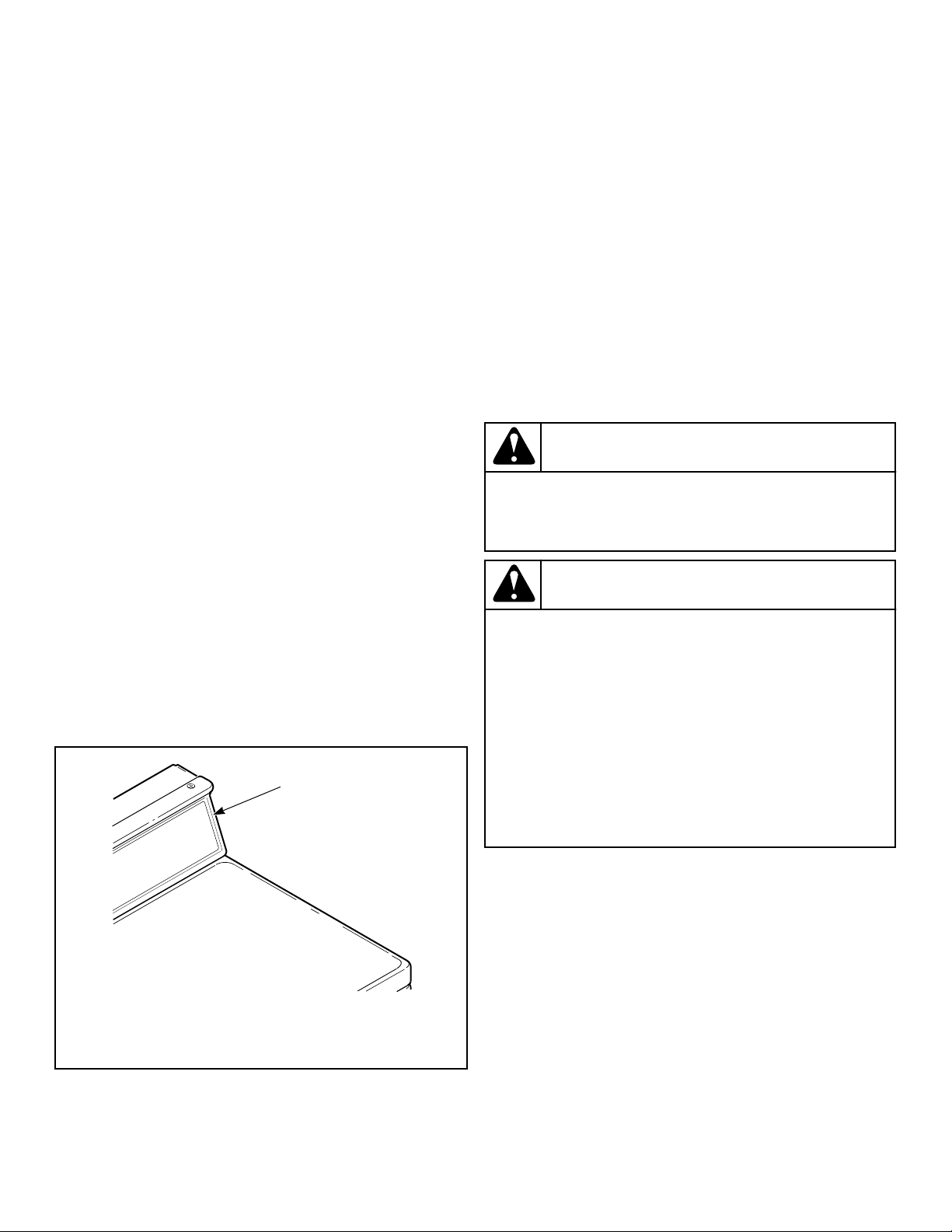
Additional Security
Located on the service door of meter case models is a flat Phillips
head screw. During shipment, this screw is used to attach the
service door to the meter case. For additional security, this screw
can be reinstalled inside the control hood of your unit. Refer to
instructions below for installation.
Tamper-resistant screws also can be installed for additional secur-
ity. Tamper-resistant screws, bits and bit holder are available as
optional equipment at extra cost. Part numbers are:
• Bit (No. 8 screws) Part No. 281P4
• Bit (No. 12 screws) Part No. 282P4
• Control panel tamper-resistant screw Part No. 35528
• Front panel tamper-resistant screw Part No. 35527
The following list is the procedure required to install the Phillips
head screw and tamper-resistant screws:
WARNING
Any disassembly requiring the use of tools must be
performed by a suitably qualified service person.
W299
WARNING
To reduce the risk of electric shock, fire, explosion,
serious injury or death:
• Disconnect electric power to the washer before
servicing.
• Never start the washer with any guards/panels re-
moved.
• Whenever earth/ground wires are removed during
servicing, these earth/ground wires must be re-
connected to ensure that the washer is properly
connected to a protective earth/ground.
W883
1. Remove the Phillips head screw from service door (refer to
Figure 14 ).
2. Remove two screws holding control panel to control hood.
3. Tilt control panel forward and lay on a protective pad to pre-
vent scratching of cabinet top.
4. Insert Phillips head screw down through double “D” hole in
left rear corner of cabinet top (inside control hood) until it en-
gages retainer nut located on left rear corner gusset of cabinet.
5. Finger tighten screw.
IMPORTANT: Do not use a power driver to tighten
screw. Torque of a power driver could over-tighten
screw causing damage to cabinet assembly.
6. Secure control panel to control hood using two No. 8 tamper-
resistant screws, Part No. 35528.
Installation
©
Copyright, Alliance Laundry Systems LLC -
DO NOT COPY or TRANSMIT
19 Part No. 205161EN
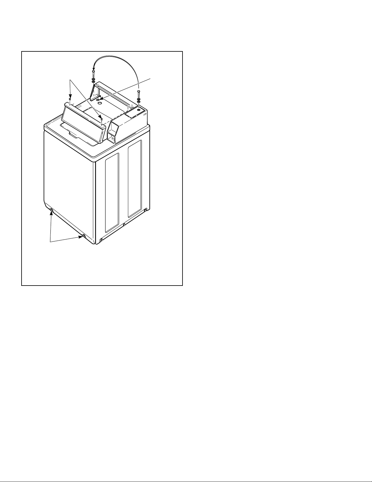
7. Remove two screws holding front panel to base of washer and
install two No. 12 tamper-resistant screws, Part No. 35527.
TLW2102N_SVG
3
2
1
1. 35528 No. 8 Screws
2. Double “D” Hole
3. 35527 No. 12 Screws
Figure 14
Installation
©
Copyright, Alliance Laundry Systems LLC -
DO NOT COPY or TRANSMIT
20 Part No. 205161EN
Operation
Operation Instructions
IMPORTANT: Prior to first wash, use an all-purpose
cleaner, or a detergent and water solution, and a damp
cloth to remove shipping dust from inside of washer.
IMPORTANT: Remove all sharp objects from laundry to
avoid tears and rips to items during normal machine
operation.
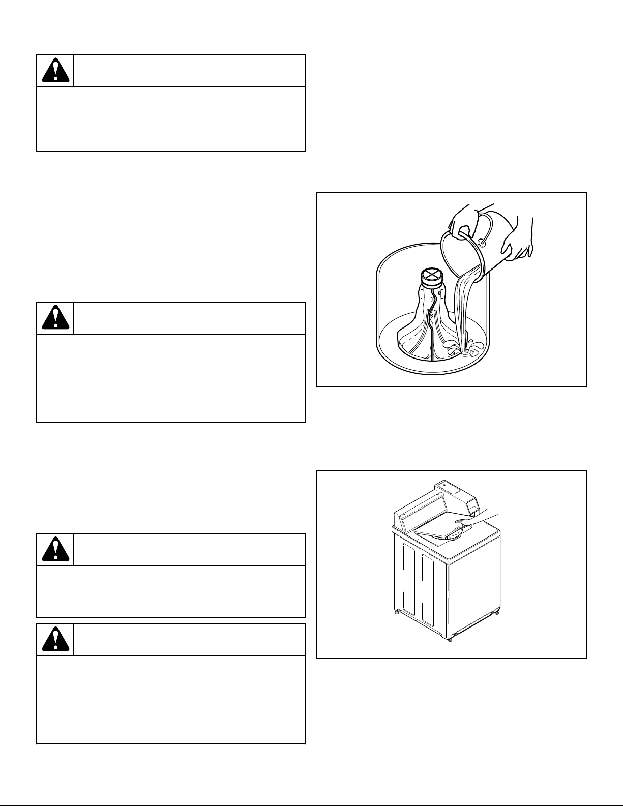
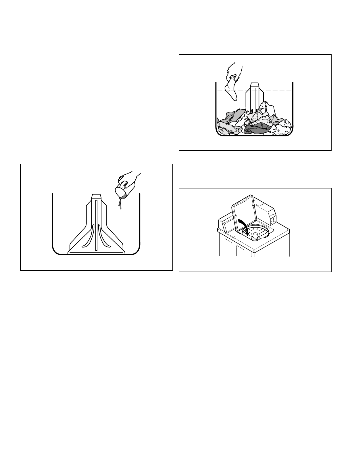
Add Detergent
1. Pour measured amount of detergent into washtub. Refer to
package directions.
2. NEVER POUR UNDILUTED BLEACH DIRECTLY ON
LAUNDRY. Follow package directions when using bleach.
W395I_SVG
Figure 15
Load Laundry
1. Load dry clothes loosely into washtub – DO NOT overload!
(14 lbs. [6.3 kg] maximum dry clothes load)
2. When washing large items such as shag rugs and bedspreads,
add several small items to balance wash load.
W392I_SVG
Figure 16
Close Lid
Washer will not operate with lid open.
TLW2202N_SVG
Figure 17
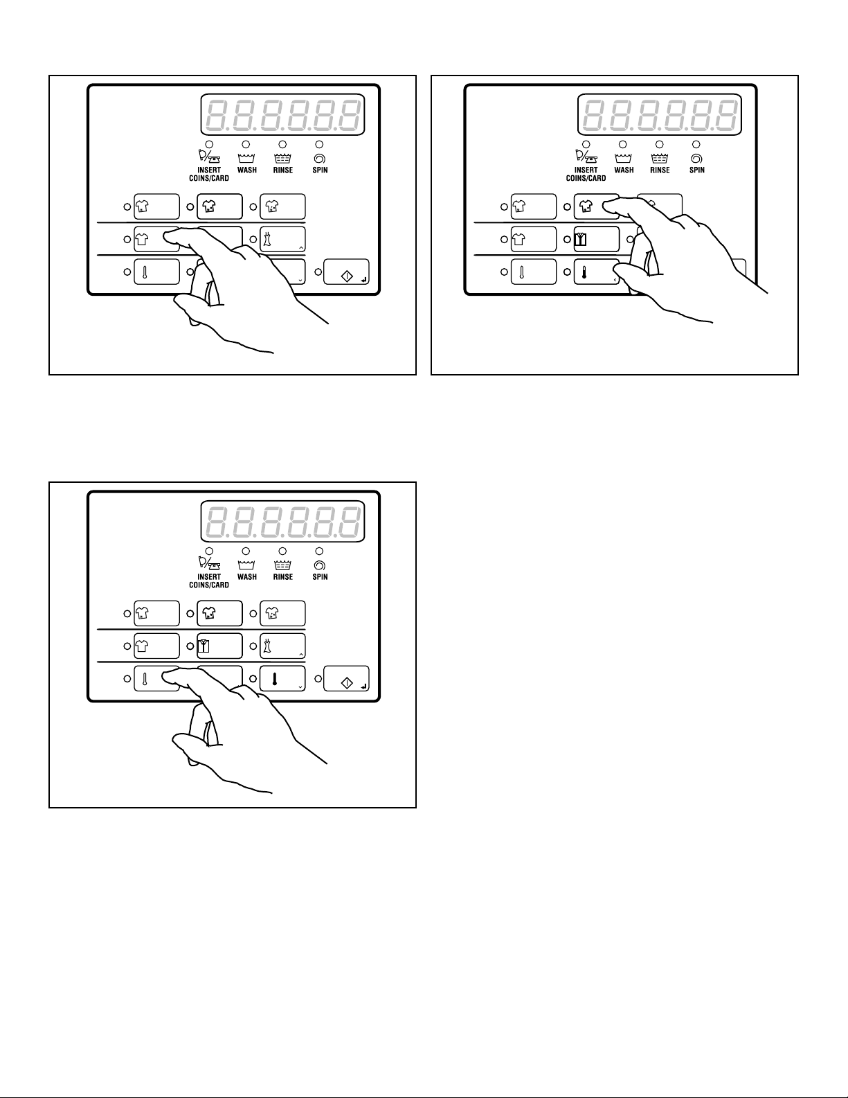
Set Cycle
Push Cycle touchpad for NORMAL, SYNTHETIC or DELI-
CATE. Light indicates selection.
NOTE: The NORMAL cycle is recommended for every-
day cottons and linens.
Operation
©
Copyright, Alliance Laundry Systems LLC -
DO NOT COPY or TRANSMIT
21 Part No. 205161EN
TLW2386N_SVG
Cycle
Wash
Temp
ULTRADELUXEREGULAR
DELICATESYNTHETICNORMAL
HOT
START
WARMCOLD
Figure 18
Set Wash Temperature
Push Temp touchpad for COLD, WARM or HOT. Light indicates
selection.
TLW2387N_SVG
Cycle
Wash
Temp
ULTRADELUXEREGULAR
DELICATESYNTHETICNORMAL
HOT
START
WARMCOLD
Figure 19
Select Wash Level
Push Wash touchpad for REGULAR, DELUXE or ULTRA.
Light indicates selection.
NOTE: The REGULAR wash level is recommended for
everyday cottons and linens.
Fabric softener should only be used when the ULTRA wash level
is selected.
TLW2388N_SVG
Cycle
Wash
Temp
ULTRADELUXEREGULAR
DELICATESYNTHETICNORMAL
HOT
START
WARMCOLD
Figure 20
Operation
©
Copyright, Alliance Laundry Systems LLC -
DO NOT COPY or TRANSMIT
22 Part No. 205161EN
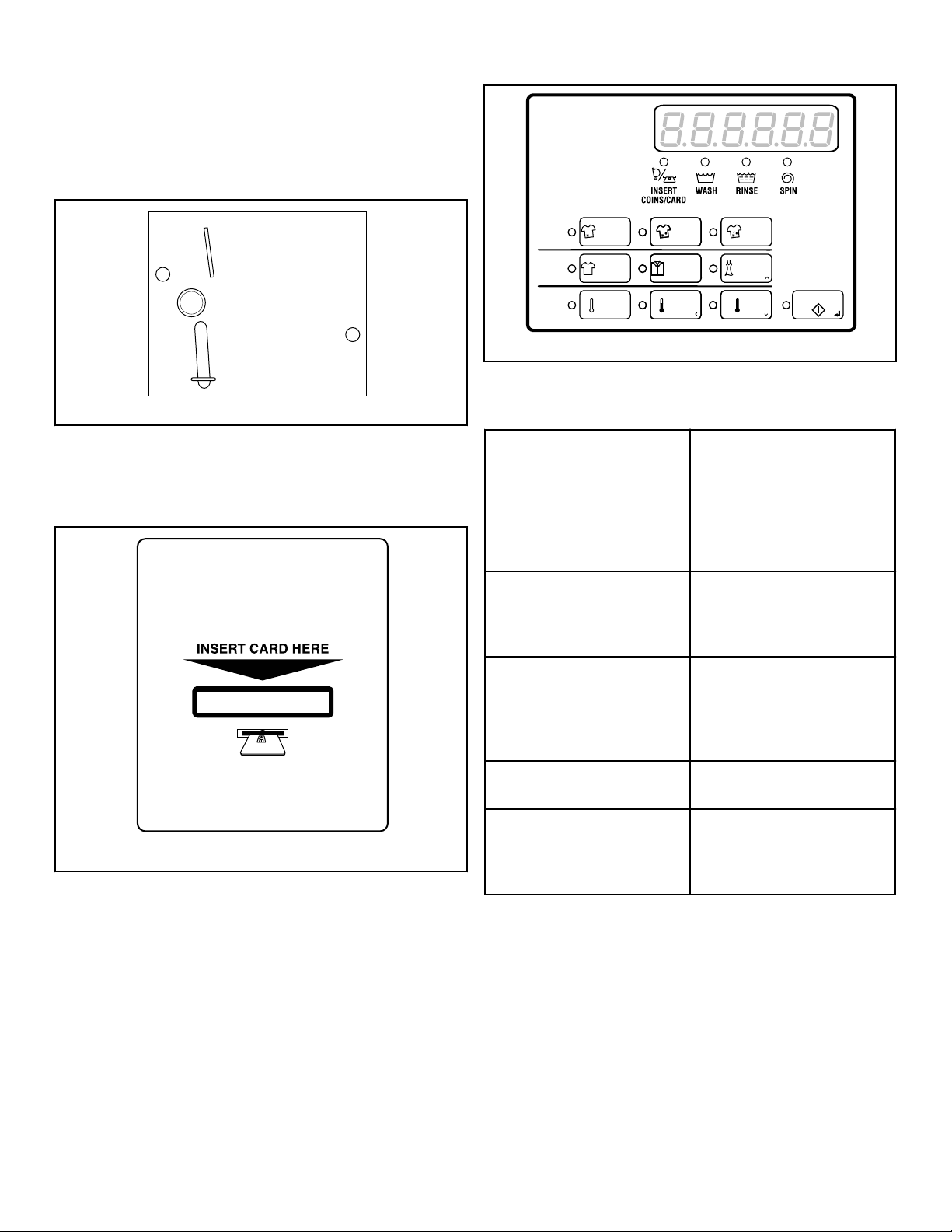
Insert Coins or Card
To Insert Coins
1. Insert coin(s) in coin slot.
2. Check pricing as seen on digital display.
W387I_SVG
Figure 21
To Insert Card
Insert card into opening.
DRY2633N_SVG
Figure 22
Start Washer
After vend price has been satisfied, push the START pad. LID
MUST BE CLOSED TO START WASHER.
TLW26C_SVG
Cycle
Wash
Temp
ULTRADELUXEREGULAR
DELICATESYNTHETICNORMAL
HOT
START
WARMCOLD
Figure 23
Indicator Lights
INSERT COINS/CARD INSERT COINS/CARD is lit
to prompt the user to insert
payment to satisfy the vend
price. When INSERT COINS/
CARD is lit, the digits show
the vend price remaining to be
satisfied.
WASH WASH is lit at the beginning
of the Wash portion of the cy-
cle and will remain lit until the
wash step is complete.
RINSE RINSE is lit at the beginning
of the Rinse or Extra Rinse
portion of the cycle and will
remain lit until the Rinse step
is complete.
SPIN SPIN is lit during the Final
Spin portion of the cycle.
START START flashes one second on
and one second off when the
full vend price has been satis-
fied.
Operation
©
Copyright, Alliance Laundry Systems LLC -
DO NOT COPY or TRANSMIT
23 Part No. 205161EN
Maintenance
User-Maintenance Instructions
Cold Weather Care
If the unit is delivered on a cold day (below freezing), or is stored
in an unheated room or area during the cold months, do not at-
tempt to operate the washer until it has had a chance to warm up.
Water from the previous cycle may remain.
Care of Your Washer
Use only a damp or sudsy cloth for cleaning the control panel.
Some cleaning products may harm the finish on the control panel
or damage the interior. DO NOT use products that contain alco-
hol on the control panel. Wipe the panel dry after cleaning.
Wipe the washer cabinet as needed. If detergent, bleach or other
washing products are spilled on the cabinet, wipe immediately.
Some products will cause permanent damage if spilled on the
cabinet.
Do not use scouring pads or abrasive cleansers on control panel
or cabinet.
The washtub will need no particular care though it may need rins-
ing or wiping after some unusual loads have been washed. This
also may be necessary if too little detergent has been used.
Leave the lid open to allow the inside of the washer to dry out
after use. This helps prevent musty odors from developing.
The agitator should not be removed except for service. The wash-
tub is designed to be self cleaning.
Replacing Hoses
Hoses and other rubber parts deteriorate after extended use. Ho-
ses may develop cracks, blisters or material wear from the tem-
perature and constant high pressure they are subjected to.
All hoses should be checked on a monthly basis for any visible
signs of deterioration. Any hose showing the signs of deteriora-
tion listed above should be replaced immediately. All hoses
should be replaced every five years.
Filter Screens
Check the filter screens in the fill hoses for debris or damage ev-
ery six months. Clean or replace them if necessary.
If the washer is filling with water slower than normal, check the
filter screens. Clean or replace them if necessary.
Order filter screen Part No. 803615 from the nearest authorized
parts distributor.
Reinstallation of Shipping Materials
You must install the shipping brace and shipping plug any time
the washer is moved.
Shipping Brace
The shipping brace in the lid opening should be saved and rein-
stalled whenever the washer is moved. To reinstall the brace,
open the washer lid and place the brace over the washer agitator,
placing the back of the brace into the lid opening first.
Shipping Plug
The plastic shipping plug should be saved and reinstalled any
time the washer is moved. The plug fits into two openings: The
base opening and the shipping plug opening on the bottom of the
movable pivot dome. The plug MUST be inserted into both open-
ings to prevent damage to the washer. In order to accomplish this,
the shipping plug opening must be directly lined up with the base
opening.
Refer to Figure 24 .
TLW2103N_SVG
2
1
4
3
1. Shipping Plug Opening
2. Base Opening
3. Shipping Plug
4. Shipping Brace
Figure 24
Motor Overload Protector
The internal overload protector will stop the motor automatically
in the event of an overload.
The overload protector will reset itself in two or three minutes
and the motor will restart automatically.
Maintenance
©
Copyright, Alliance Laundry Systems LLC -
DO NOT COPY or TRANSMIT
24 Part No. 205161EN

If the overload protector stops motor again, remove the washer
from use and call the service person to correct the problem.
Maintenance
©
Copyright, Alliance Laundry Systems LLC -
DO NOT COPY or TRANSMIT
25 Part No. 205161EN

Troubleshooting
Try these troubleshooting tips before making a service call. They
may save you time and money.
Washer Symptom Possible Cause/Solution
Won’t Fill • Make sure lid is closed.
• Make sure power cord is plugged all the way into the electrical outlet.
• Check the laundry room fuse or circuit breaker.
• Insert coin(s) or card.
• Make sure that the controls are properly set.
• Make sure hot and cold water faucets are turned on.
• Make sure drain hose is not kinked or twisted.
• During the rinse portion of the cycle, the tub won’t fill with water. Instead, there is a
spray rinse.
• Make sure that the last spin has been completed.
• Clean the screens in the water mixing valve and the filter screens located at the faucet
end of the fill hoses. (Owner is responsible for service calls regarding cleaning of the
screens.)
• Water is being siphoned from the washer during the cycle. Refer to the Installation
instructions to make sure that the drain hose has been properly installed.
• The motor overload protector may have stopped the cycle. It will reset itself in two or
three minutes and restart the washer automatically.
Won’t Start • Make sure lid is closed.
• Make sure power cord is plugged all the way into the electrical outlet.
• Check the laundry room fuse or circuit breaker.
• Insert coin(s) or card.
• Make sure that the controls are properly set.
• The motor overload protector may have stopped the cycle. It will reset itself in two or
three minutes and restart the washer automatically.
Won’t Agitate • Make sure lid is closed.
• Make sure power cord is plugged all the way into the electrical outlet.
• Check the laundry room fuse or circuit breaker.
• Insert coin(s) or card.
• The motor overload protector may have stopped the cycle. It will reset itself in two or
three minutes and restart the washer automatically.
• Broken drive belt. Call the service person.
• Have a qualified electrician check polarity and earth/ground. Refer to Electrical Re-
quirements section.
Table continues...
Troubleshooting
©
Copyright, Alliance Laundry Systems LLC -
DO NOT COPY or TRANSMIT
26 Part No. 205161EN

Washer Symptom Possible Cause/Solution
Won’t Spin • Make sure lid is closed.
• Make sure power cord is plugged all the way into the electrical outlet.
• Check the laundry room fuse or circuit breaker.
• Insert coin(s) or card.
• The motor overload protector may have stopped the cycle. It will reset itself in two or
three minutes and restart the washer automatically.
• Broken drive belt. Call the service person.
• Have a qualified electrician check polarity and earth/ground. Refer to Electrical Re-
quirements section.
Stops/Pauses During Cycle • Pauses are part of the washer’s normal operation. The washer will stop (pause) shortly
before the wash and rinse spins.
• Check the laundry room fuse or circuit breaker.
• The motor overload protector may have stopped the cycle. It will reset itself in two or
three minutes and restart the washer automatically.
Won’t Drain • Make sure drain hose is not kinked or twisted.
• Make sure drain hose is not clogged.
• Make sure drain receptacle is not clogged.
• Refer to the Installation instructions to make sure that the drain hose has been proper-
ly installed.
Water Leaks • Check that fill hoses are properly installed on the faucets and the washer’s water mix-
ing valve.
• Check the condition of the fill hoses. Replace fill hoses every five years.
• Make sure drain receptacle is not clogged.
• Check laundry room plumbing.
• Laundry load may be oversudsing or overloaded. Use less detergent (or low-sudsing
detergent) and proper load sizes.
Is Noisy • Wash load may be unbalanced. Open lid and redistribute the load.
• Make sure washer is level. Uneven leveling can cause vibration.
• A newly installed washer may make a knocking sound if the machine has been in stor-
age. The belt may have settled. Run washer through 4-5 cycles to loosen belt. Washer
operation will not be affected.
Load is too Wet • Wash load may be unbalanced. Open lid and redistribute the load.
• Load is too small. Add items to make full load.
Wrong Water Temperature • Make sure that the controls are properly set.
• Check fill hoses. Make sure hot faucet hose is connected to hot mixing valve (indica-
ted with “H” on the valve bracket) and cold faucet is connected to cold mixing valve
(indicated with “C” on the valve bracket).
• Make sure laundry room water heater is adjusted properly.
Troubleshooting
©
Copyright, Alliance Laundry Systems LLC -
DO NOT COPY or TRANSMIT
27 Part No. 205161EN
Contact Information
If service is required, contact the nearest Factory Authorized
Service Center.
If you are unable to locate an authorized service center or are un-
satisfied with the service performed on your unit, contact:
Alliance Laundry Systems
Shepard Street
P.O. Box 990
Ripon, WI 54971-0990
U.S.A.
www.alliancelaundry.com
Phone: +1 (920) 748-3121
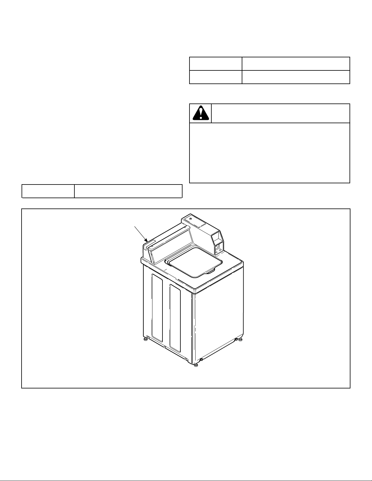
When calling or writing about your unit, PLEASE GIVE THE
MODEL AND SERIAL NUMBERS. The model and serial num-
bers are located on the serial plate. The serial plate will be in the
location shown in Figure 25 .
Date Purchased
Table continues...
Model Number
Serial Number
Please include a copy of your bill of sale and any service receipts
you have.
WARNING
To reduce the risk of serious injury or death, DO NOT
repair or replace any part of the unit or attempt any
servicing unless specifically recommended in the
user-maintenance instructions or in published user-
repair instructions that you understand and have the
skills to carry out.
W329
If replacement parts are required, contact the source from where
you purchased your unit or call +1 (920) 748-3950 for the name
and address of the nearest authorized parts distributor.
TLW12C_SVG1
1
1. Serial Plate
Figure 25
Contact Information
©
Copyright, Alliance Laundry Systems LLC -
DO NOT COPY or TRANSMIT
28 Part No. 205161EN
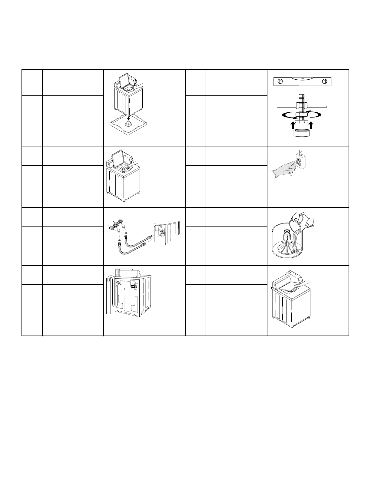
Installer Checklist
Fast Track for Installing the Washer
1 Remove the Shipping
Brace and Shipping
Plug.
TLW2098N_SVG1
5 Position and Level the
Washer.
TLW2201N_SVG
CHECK CHECK
2 Wipe Out Inside of
Washer.
TLW2099N_SVG
6 Plug In the Washer.
TLW2289N_SVG
CHECK CHECK
3 Connect Fill Hoses.
TLW1988N_SVG
HOT
COLD
7 Add Water to the
Washer.
TLW2056N_SVG
CHECK CHECK
4 Connect Drain Hose to
Drain Receptacle.
TLW2251N_SVG1
8 Check Lid Switch.
TLW2101N_SVG
CHECK CHECK
Refer to the manual for more detailed information
Installer Checklist
©
Copyright, Alliance Laundry Systems LLC -
DO NOT COPY or TRANSMIT
29 Part No. 205161EN
