Loading ...
1-1
1-4
1-2 1-3
2
Important Safety Instructions
Installation
SAVE THESE INSTRUCTIONS
This manual contains instructions and warnings that should be followed during
the installation, operation, and storage of this product. Failure to heed these
instructions and warnings may affect the product warranty.
• The PDU provides convenient multiple outlets, but it DOES NOT provide surge or line noise
protection for connected equipment.
• The PDU is designed for indoor use only in a controlled environment away from excess
moisture, temperature extremes, conductive contaminants, dust or direct sunlight.
• Do not connect the PDU to an ungrounded outlet or to extension cords or adapters that
eliminate the connection to ground.
• The power requirement for each piece of equipment connected to the PDU must not exceed
the individual outlet’s load rating.
• The total power requirement for equipment connected to the PDU must not exceed the
maximum load rating for the PDU.
• Do not drill into or attempt to open any part of the PDU housing. There are no user-serviceable
parts inside.
• Do not attempt to modify the PDU, including the input plugs and power cables.
• Do not attempt to use the PDU if any part of it becomes damaged.
• Do not attempt to mount the PDU to an insecure or unstable surface.
• Use of this equipment in life support applications where failure of this equipment can
reasonably be expected to cause the failure of the life support equipment or to signicantly
affect its safety or effectiveness is not recommended. Do not use this equipment in the
presence of a ammable anesthetic mixture with air, oxygen or nitrous oxide.
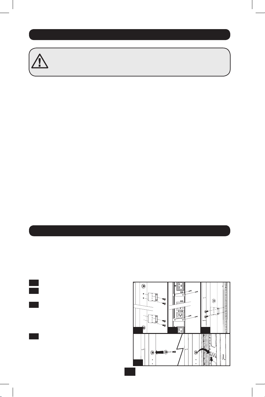
Mounting the PDU
Note: The illustrations may differ somewhat from your PDU model. Regardless of configuration, the user must
determine the fitness of hardware and procedures before mounting. The PDU and included hardware are designed
for common rack and rack enclosure types and may not be appropriate for all applications. Exact mounting
configurations may vary. Screws for attaching the mounting brackets and cord retention shelf to the PDU are
included. Use only the screws supplied by the manufacturer, or their exact equivalent (#6-32, ¼” flat head).
1-1
Attach the mounting brackets to the PDU.
1-2
(Optional) Attach the cord retention
bracket(s) to the PDU.
1-3
Attach the PDU to a vertical rail in your
rack or rack enclosure. (Use the mounting
hardware that came with your rack or rack
enclosure to attach the mounting brackets
to the rail.)
1-4
For toolless mounting, attach the included
mounting buttons to the PDU. Position the
PDU as desired in the rack enclosure, align
the buttons with the rack mounting slots,
and slide the PDU into position.
201104185 93-2906.indb 2 5/18/2011 1:35:59 PM
Loading ...
Loading ...
Loading ...