Safety Instructions
Any maintenance and repair work must be carried out
by trained experts. Failure to do so may result in the
failure of the TPMS sensor. LAUNCH does not
assume any liability in case of faulty or incorrect
installation of the unit.
CAUTION
Do not race with the vehicle on which the LTR-01
RF sensor is mounted, and always keep the
drive speed under 240km/h.
To guarantee optimal performance, the sensors
may only be installed with original valves and
accessories provided by LAUNCH.
Make sure to program the sensors using
LAUNCH-specific TPMS tool prior to
installation.
Do not install programmed TPMS sensors in
damaged wheels.
After installing the TPMS sensor, test the
vehicle’s TPMS following the steps described in
the original manufacturer’s user manual to
confirm proper installation.
When mounting/dismounting the wheel, follow
the operation guideline of wheel changer
manufacturer strictly.
RF-Sensor
QuickStartGuide
LTR-03
IMPORTANT: Read these instructions
carefully and use this unit properly before
operating. Failure to do so may cause damage
and/or personal injury and will void the product
warranty.
www.x431.com
LAUNCH
+86-755-84557891
overseas.service@cnlaunch.com
- Increase the separation between the equipment
and receiver.
- Connect the equipment into an outlet on a circuit
different from that to which the receiver is
connected.
FCC Warning
- Reorient or relocate the receiving antenna.
Note: Any changes or modifications not expressly
approved by the party responsible for compliance
could void the user's authority to operate the
equipment. This equipment has been tested and
found to comply with the limits for a Class B digital
device, pursuant to part 15 of the FCC Rules. These
limits are designed to provide reasonable protection
against harmful interference in a residential
installation. This equipment generates uses and can
radiate radio frequency energy and, if not installed
and used in accordance with the instructions, may
cause harmful interference to radio communications.
However, there is no guarantee that interference will
not occur in a particular installation. If this equipment
does cause harmful interference to radio or television
reception, which can be determined by turning the
equipment off and on, the user is encouraged to try to
correct the interference by one or more of the
following measures:
- Consult the dealer or an experienced radio/TV
technician for help.
This device complies with part 15 of the FCC Rules.
Operation is subject to the following two conditions:
(1) This device may not cause harmful interference,
and (2) this device must accept any interference
received, including interference that may cause
undesired operation.
Disclaimer of Warranties and
Limitation of Liabilities
All information, illustrations, and specifications in
this manual are based on the latest information
available at the time of publication. The right is
reserved to make changes at any time without
notice. We shall not be liable for any direct, special,
incidental, indirect damages or any economic
consequential damages (including the loss of
profits) due to the use of the document.
Warranty
The sensor is guaranteed to be free from material
and manufacturing defects for a period of twenty-four
(24) months or for 31000 miles, whichever comes
first. This warranty covers any defects in materials or
workmanship under normal use during the warranty
period. Excluded from the warranty are defects due
to improper installation and usage, induction of
defect by other products, damage due to collision or
tire failure.
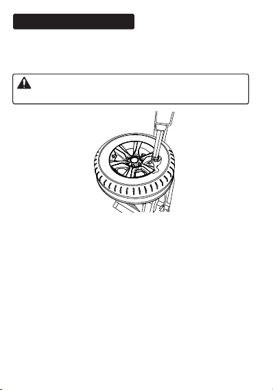
Place the tire on the rim, ensure that the valve starts
on the opposite side of the rim from the tire fitting
head. Mount the tire over the rim.
5. Remounting the tire
Caution: Strictly follow tire changer manufacturer’s
instructions to mount the tire.
Caution: Make sure that the nut and cap are installed
on the outside of the rim.
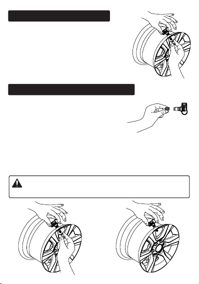
3. Dismounting the sensor
Remove the cap and nut from
the valve stem, and then
remove the sensor assembly
from the wheel rim.
4. Mounting the sensor and valve
Step 1. Remove the cap and
nut from the valve stem.
Step 2. Place the valve stem through the valve hole of
the rim, ensuring the sensor body located on the
inside of the rim. Assemble the nut back on the valve
stem with a torque of 4N·m, then tighten the cap.
T
W
C
-
4
1
1
N
I
C
Caution: The bead loosener must be facing the
valve.
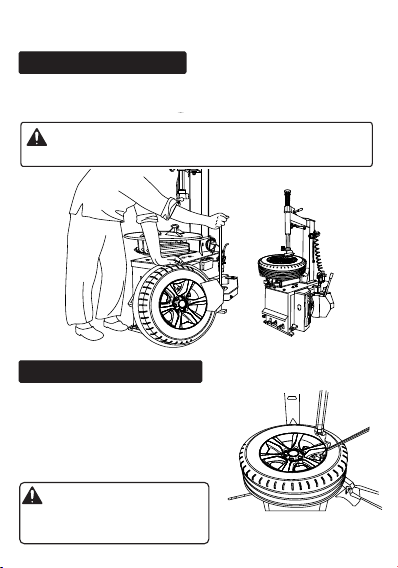
InstallationSteps
Use the bead loosener to break the tire bead.
1. Loosening the tire
Remove the valve cap and nut and deflate the tire.
2. Dismounting the tire
Clamp the tire on the tire
changer, and adjust the valve
at 1 o’clock to the tire fitting
head. Use the tire tool to
dismount the tire bead.
Caution: Always observe
this starting point during the
whole dismounting process.
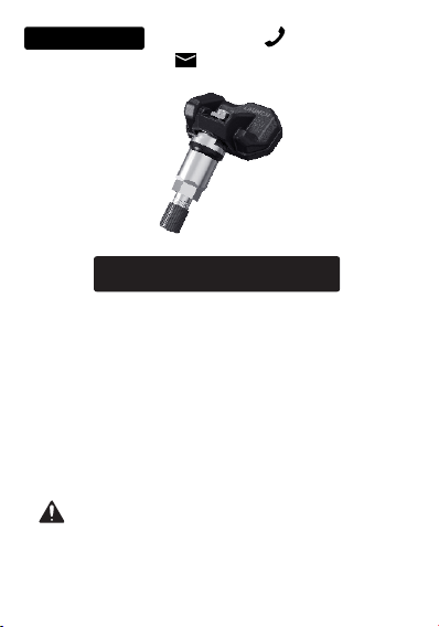
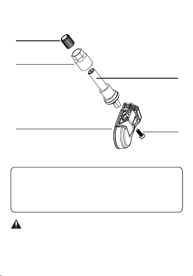
Sensor body
Washer&nut
Valvestem
Rubbergrommet
andvalvecore
assembly
Screw
Cap
Weight <30g
Technical Parameters
Dimension(L*W*H) About 72*51*27mm
Working Voltage 3V
IP Rating IP67
Components&Controls
When replacing or servicing the sensor, please only
use the original valves and accessories provided by
LAUNCH to ensure proper sealing. It is mandatory to
replace the sensor if it is externally damage. Always
remember to tighten the nut to the correct torque of 4N·m.
Warranty
The sensor is guaranteed to be free from material
and manufacturing defects for a period of twenty-four
(24) months or for 31000 miles, whichever comes
first. This warranty covers any defects in materials or
workmanship under normal use during the warranty
period. Excluded from the warranty are defects due
to improper installation and usage, induction of
defect by other products, damage due to collision or
tire failure.
Place the tire on the rim, ensure that the valve starts
on the opposite side of the rim from the tire fitting
head. Mount the tire over the rim.
5. Remounting the tire
Caution: Strictly follow tire changer manufacturer’s
instructions to mount the tire.
Caution: Make sure that the nut and cap are installed
on the outside of the rim.
3. Dismounting the sensor
Remove the cap and nut from
the valve stem, and then
remove the sensor assembly
from the wheel rim.
4. Mounting the sensor and valve
Step 1. Remove the cap and
nut from the valve stem.
Step 2. Place the valve stem through the valve hole of
the rim, ensuring the sensor body located on the
inside of the rim. Assemble the nut back on the valve
stem with a torque of 4N·m, then tighten the cap.
T
W
C
-
4
1
1
N
I
C
Caution: The bead loosener must be facing the
valve.
InstallationSteps
Use the bead loosener to break the tire bead.
1. Loosening the tire
Remove the valve cap and nut and deflate the tire.
2. Dismounting the tire
Clamp the tire on the tire
changer, and adjust the valve
at 1 o’clock to the tire fitting
head. Use the tire tool to
dismount the tire bead.
Caution: Always observe
this starting point during the
whole dismounting process.
Sensor body
Washer&nut
Valvestem
Rubbergrommet
andvalvecore
assembly
Screw
Cap
Weight <30g
Technical Parameters
Dimension(L*W*H) About 72*51*27mm
Working Voltage 3V
IP Rating IP67
Components&Controls
When replacing or servicing the sensor, please only
use the original valves and accessories provided by
LAUNCH to ensure proper sealing. It is mandatory to
replace the sensor if it is externally damage. Always
remember to tighten the nut to the correct torque of 4N·m.

Safety Instructions
Any maintenance and repair work must be carried out
by trained experts. Failure to do so may result in the
failure of the TPMS sensor. LAUNCH does not
assume any liability in case of faulty or incorrect
installation of the unit.
CAUTION
Do not race with the vehicle on which the LTR-01
RF sensor is mounted, and always keep the
drive speed under 240km/h.
To guarantee optimal performance, the sensors
may only be installed with original valves and
accessories provided by LAUNCH.
Make sure to program the sensors using
LAUNCH-specific TPMS tool prior to
installation.
Do not install programmed TPMS sensors in
damaged wheels.
After installing the TPMS sensor, test the
vehicle’s TPMS following the steps described in
the original manufacturer’s user manual to
confirm proper installation.
When mounting/dismounting the wheel, follow
the operation guideline of wheel changer
manufacturer strictly.
RF-Sensor
QuickStartGuide
LTR-03
IMPORTANT: Read these instructions
carefully and use this unit properly before
operating. Failure to do so may cause damage
and/or personal injury and will void the product
warranty.
www.x431.com
LAUNCH
+86-755-84557891
overseas.service@cnlaunch.com
- Increase the separation between the equipment
and receiver.
- Connect the equipment into an outlet on a circuit
different from that to which the receiver is
connected.
FCC Warning
- Reorient or relocate the receiving antenna.
Note: Any changes or modifications not expressly
approved by the party responsible for compliance
could void the user's authority to operate the
equipment. This equipment has been tested and
found to comply with the limits for a Class B digital
device, pursuant to part 15 of the FCC Rules. These
limits are designed to provide reasonable protection
against harmful interference in a residential
installation. This equipment generates uses and can
radiate radio frequency energy and, if not installed
and used in accordance with the instructions, may
cause harmful interference to radio communications.
However, there is no guarantee that interference will
not occur in a particular installation. If this equipment
does cause harmful interference to radio or television
reception, which can be determined by turning the
equipment off and on, the user is encouraged to try to
correct the interference by one or more of the
following measures:
- Consult the dealer or an experienced radio/TV
technician for help.
This device complies with part 15 of the FCC Rules.
Operation is subject to the following two conditions:
(1) This device may not cause harmful interference,
and (2) this device must accept any interference
received, including interference that may cause
undesired operation.
Disclaimer of Warranties and
Limitation of Liabilities
All information, illustrations, and specifications in
this manual are based on the latest information
available at the time of publication. The right is
reserved to make changes at any time without
notice. We shall not be liable for any direct, special,
incidental, indirect damages or any economic
consequential damages (including the loss of
profits) due to the use of the document.