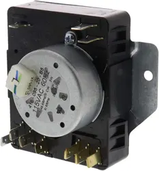
INSTALLATION INSTRUCTIONS
Dealer Replacement Motor / Metal Geared Cam Kit
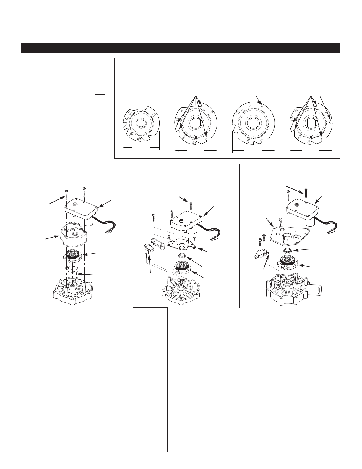
DETERMINE WHICH CAM
TO USE
Compare the diameter and number
of drops (notches) of the existing
cam in your system’s valve to
determine which new cam to use.
Use the same size and type new
cam (see illustration at right).
2-1/4"
2-5/8" 2-5/8"
2-5/8"
P/N 7284964
Cam for
3/4” Valve
(lettered side up)
P/N 7
283489
Cam for 1” SD
Residential Valve
(lettered side up)
1. Push the system’s bypass valve into the bypass position.
2. Unplug the system’s power supply from electrical power.
3. Remove the top cover to get access to the valve.
4. Locate the cable (red and black wires) running from the motor to the
electronic control board and unplug the 2-pin connector.
5. Remove the motor’s mounting screws and lift the motor off the molded
plastic mount.
6. Lift the plastic mount off the valve cover and set this part aside, as it
will be reused.
7. Lift the old geared cam off the stem of the valve rotor.
8. Examine the hole in the center of the new geared cam and see how it
has two flat sides, one longer than the other. Place it gently over the
stem of the valve rotor, oriented the same way. Do not press it down
yet.
9. Locate the lever on the microswitch and push it in (toward the switch
body). Hold it in this position while gently lowering the geared cam
onto the stem.
10. Release the microswitch lever. It should be resting in an indent on the
side of the cam - not bent down underneath the cam.
11. Put the molded plastic mount back in place onto the valve cover.
12. Install the new motor (screws provided) onto the mount and valve
cover, making sure that the motor stem’s teeth engage properly with
the new geared cam.
13. Plug the new motor’s cable (red and black wires) into the correspon-
ding 2-pin connector from the electronic control board.
14. Put the top cover back on the system, plug the power supply back into
electrical power and place the bypass valve back into service position.
15. Start a recharge to make sure the motor runs and is properly engaged
to the valve rotor. Advance the valve through all positions until it
reaches service again.
1. Push the system’s bypass valve into the bypass position.
2. Unplug the system’s power supply from electrical power.
3. Remove the top cover to get access to the valve.
4. Locate the cable (red and black wires) running from the motor to the electronic
control board and unplug the 2-pin connector.
5. Remove the motor’s mounting screws and lift the motor off the mounting plate.
6. Remove the plate’s mounting screws and lift the plate off the valve cover. Set these
parts aside, as they will be reused.
7. Lift the plastic bushing off the old geared cam and set this bushing aside to be reused.
8. Lift the old geared cam off the stem of the valve rotor.
9. Examine the hole in the center of the new geared cam and see how it has two flat
sides, one longer than the other. Place it gently over the stem of the valve rotor,
oriented the same way. Do not press it down yet.
10. Locate the lever on the microswitch and push it in (toward the switch body). Hold it
in this position while gently lowering the geared cam onto the stem.
11. Release the microswitch lever. It should be resting in an indent on the side of the
cam - not bent down underneath the cam.
12. Place the plastic bushing over the center of the new geared cam.
13. Reinstall the motor plate with its screws onto the valve cover.
14. Install the new motor (screws provided) onto the plate, making sure that the motor
stem’s teeth engage properly with the new geared cam.
15. Plug the new motor’s cable (red and black wires) into the corresponding 2-pin con-
nector from the electronic control board.
16. Put the top cover back on the system, plug the power supply back into electrical
power and place the bypass valve back into service position.
17. Start a recharge to make sure the motor runs and is properly engaged to the valve
rotor. Advance the valve through all positions until it reaches service again.
7384798 (Rev. A 3/26/20)
3/4” VALVE WITH
MOLDED PLASTIC MOUNT
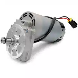
Motor
(included)
Motor Screws
6-19 x 1-3/8”
long (included)
Molded
Plastic
Mount
Microswitch
Lever
Geared
Cam
(included)
Geared
Cam
(included)
Motor
(included)
Bushing
Mounting
Plate
Bushing
Mounting
Plate
Geared
Cam
(included)
Motor Screws
8-32 x 1” long
(included)
Micro -
switch
Lever
3/4” VALVE WITH
METAL MOUNTING PLATE
1” VALVE
Motor Screws
8-32 x 1” long
(included)
Motor
(included)
Micro -
switch
Lever
IMPORTANT: If the geared cam on
your system’s valve is black plastic
(not silver color ed metal), it is
incompatible with the new motor
contained in this kit. When replac-
ing an old motor and/or an old
geared cam, you must replace both
w
ith the ones provided in this kit.
MOTORS AND GEARED CAMS MUST BE REPLACED AS A SET
P/N 7335024
Cam for 1” AIV
Filter Valve
(lettered side up)
P/N 7283502
Cam for 1” SD
Commercial Valve
(lettered side up)
5 Drops 6 DropsAspirate Position