Loading ...
Loading ...
Undernormal conditiotas, best results will be ob-
tained by using a 1/3 horsepower 1750 R.P,M.
motor. For continuous heavy duty work, a _ horse-
_ower motor of the same speed is recommended. By
Mng a four step motor pulley the same size as the
spindle pulley, the following recommended speeds
may be ffhtained.
Work Diameter R.P,M, Roughing R.P.M. F_rli_hiag
Up to 2" 2325 3450
2" to 3" I325 2250
3" to 5" 825 1350
5" to 9" 825 875
The following table shows the diameter of the
pulley step in which the belt should be placed
in order to obtain the desired speed in Revo-
lutions Per Minute.
Latl_€ Pulley Motor Pulley
R,P.M. Step Dis. Step Dis.
3450 2" 4"
22.50 2_"
875 4" 2"
The four step motor pulley mentioned may be
obtained from your Sears retail store or mail order
house. Be sure to specify the shaft diameter of your
motor when ordering this pulley,
¢ONTROLS_ See Hgure I
TAILSTOCK lOCK:
Major adjustment of distance between centers may
be made by loosening the tailatock lock allowing
the operator to move the tailstock along the tubular
bed to a desired position. The tailstock 10ck must
be securely tightened before the work is under
power.
HANDWHEEL:
Minor adjustments of distance between centers are
made by turning the handwheel thus moving the
cup center toward or away from the work piece as
desired.
TAILSTOCK RAM LOCK:
As its name indicates, the ram lock holds the ram
in a fixed position so that it will not move and
loosen its grip on the work piece as a result of vibra-
tion. The tailstoekram must be locked securelyin
poaltion during cutting operations on work between
centers,
TO01. Sk|D| LOCK (:LAMP HANOLIs
Loosen the slide lock handle to change the angle
of the tool _st holder or to change its position on
the tubular bed, After the desired adjustment has
been made re-tighten the handle,
TOOL REST LOCKt
Tool rest is fully adjustable for any turning opera-
lion, It is held ,ecurely by the tool rest lock.
INDIX|NG PINI
:::'The.indcs2ng pin is in line with a series of,_6
equally apBced holes in the surface of the step puney
inside the headstock. This spring loaded pin, when
3
allowed to project through the casting and into a
hole in the pulley, locks the entire turning assembly
attached to the spindle.
Through the use of this pin, the spindle may be
held stationary for various operations such as laying
out patterns and centerlines on face plate work. The
index pin provides a means of spacing the various
cuts in fluting and feeding operations,
Do not use indexing pin for attaching or remov_
of f_ace plates. A drilled hole in the headstock
spindle collar is provided to remove face plates, An
Allen wrench, large nail, or any similar item, ap-
proximately the same size as the hole, can be inserted
and revolved until it bears against the indexing
plunger. This will lock the spindle and a_low the
face plate to be unscrewed.
With the index pin engaged, the latb, e may be
used as a fixture for holding long twist or spiral work
for the hand finishing operations, it is always a good
policy to double check all control units before ap-
plying power with a job set up in the lathe, q_e
operator should be sure that the tailstock and the
tailstock ram are securely locked, that the tool rest
and toot rest holder are held rigidly in position, that
the belt is in the right pulley groove for the speed
desired, and finally that the index pin is retracted
and clear of the pulley.
The set screw, No. 30, in the tailstock should be
checked occasionally to assure the proper pressure
against the key and to keep taitstock at 90 _'_to the
tubular'bed.
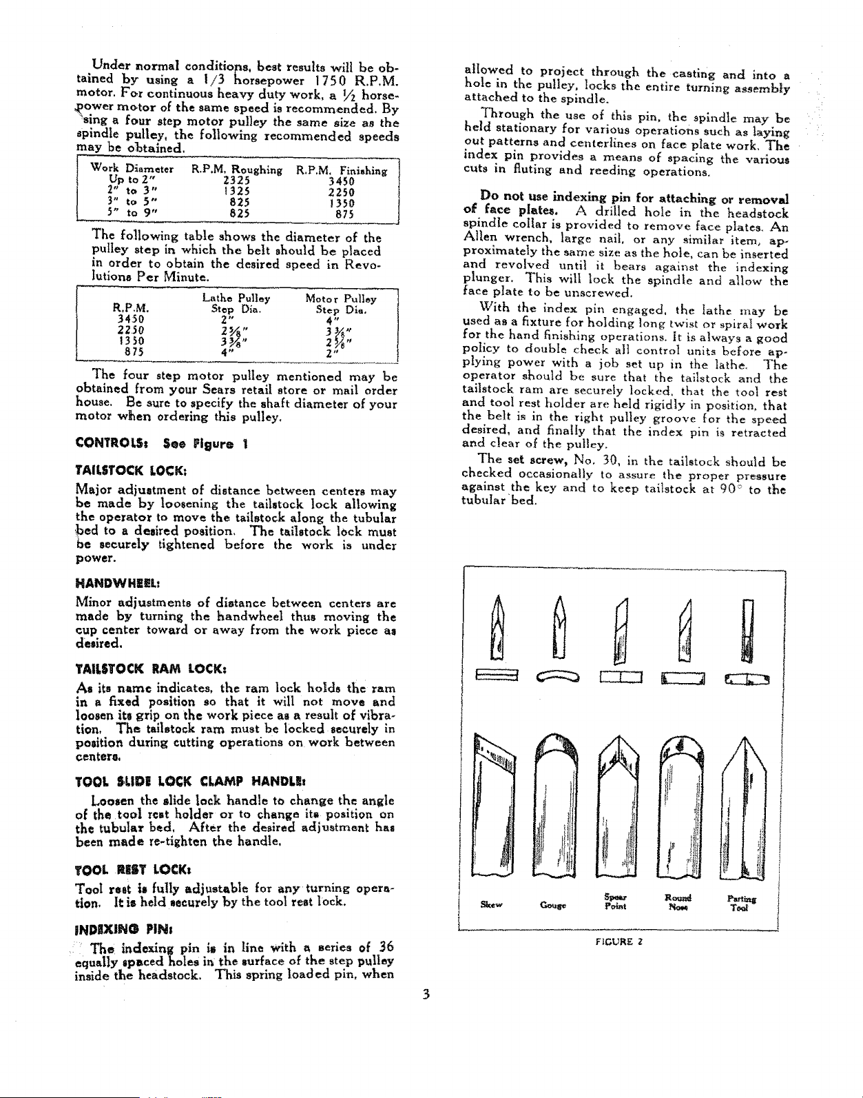
"-_!t
Sk,e_
!
k
P¢h_t
Roland
FIGURE 2
Loading ...
Loading ...
Loading ...