
Owner's ManuaB
®
15o5 HP
ELECTRIC START
42" MOWER
HYDROSTATIC (AUTOMATn¢)
LAWN TRACTOR
Model No.
917,271021
Safety
o Assernbny
Operation
o Maintenance
o Repair Parts
CAU=RON:
Read and follow all
Safety Rules and Instructions
before operating this equip-
ment.
For answers to your questions
about this product, Call:
1=800=659-5917
Sears Craftsm,an Help Line
5 am - 5 pm, M0n - Sat
Sears, Roebuck and Co., Hoffman Estates, IL 60179
Warranty ..................................................... 2 Product Specifications ............................ 19
Safety Rules ................................................ 2 Service and Adjustments ........................ 22
Assembly ............................ _+,,,i++.+.ii_.o+o........6 storage..:_,i!:.+.L+_+:,+o:._++.......................... 29
operation ............................................... 11 Troubleshooting ........................................ 30
Maintenance Schedule ............................. 18 Repair Parts ......................................... 36
Maintenance .......................................... 18 Parts Ordering ........................ Back Cover
LIMITED TWO YEAR WARRANTY ON CRAFTSMAN RIDING EQUIPMENT
For two (2) years from the date of purchase, if this Craftsman Riding Equipment is main-
tained, lubricated and tuned up according to the instructions in the owner's manual,
Sears will repair or replace, free of charge, any parts found to be defective in rnaterial or
workmanship.
This Warranty does not cover':
. Expendable items which become worn during normal use, such as blades, spark
plugs, air cleaners, belts, etc+
o Tire replacement or repair caused by punctures from outside objects, such as nails,
thorns, stumps, or glass+
o Repairs necessary because of operator abuse, negligence, improper storage or acci-
dent or the failure to maintain the equipment according to the instructions contained in
the owner's manual.
. Riding equipment used for commercial or rental purposes.
LIMITED 90 DAY WARRANTY ON BATTERY
For ninety (90) days from date of purchase, if any battery included with this riding equip-
ment proves defective in material or workmanship and our testing determines the bat-
tery will not hold a charge, Sears will replace the battery at no charge+ In-home warranty
service on your Craftsman riding equipment is available at no charge for 30 days from
the date of purchase. Please contact your nearest service center+ After 30 days from the
date of purchase, warranty service is available by taking your Craftsman riding equip-
ment to your nearest Sears Service Center: (In-home warranty service will still be avail-
able after 30 days from the date of purchase but a standard trip charge will apply)+ This
warranty applies only while this product is in the United States+ This Warranty gives you
specific legal rights, and you may also have other rights which may vary from state to
state.
Sears, Roebuck and Co. D/817 WA, Hoffman Estates, IL 60179
GENERAL OPERATION
o Read, understand, and follow all instruc-
tions in the manual and on the machine
before starting+
o Only allow responsible adults, who are
familiar with the instructions, to operate
the machine+
• Clear the area of objects such as rocks,
toys, wire, etc. which could be picked
up and thrown by the blade+
. Be sure the area is clear of other people
before mowing+ Stop machine if anyone
enters the area.
2
° Never carry passengers,
° Do not mow in reverse unless absolute-
ly necessary. Always look down and
behind before and while backing°
o Be aware of the mower discharge direc-
tion and do not point it at anyone. Do
not operate the mower without either
the entire grass catcher or the guard in
place.
o Slow down before turning,
,, Never leave a running machine unat-
tended. Always turn off blades, set park-
ing brake, stop engine, and remove
keys before dismounting°

o Turnoffbladeswhennotmowing
o Stopenginebeforeremovinggrass
catcheroruncloggingchute.
o Mowonlyindaylightorgoodartificial
lighL
o Donotoperatethe machinewhileunder
theinfluenceofalcoholordrugs
o Watchfortrafficwhenoperatingnearor
crossingroadways.
° Use extra care when loading or unload-
ing the machine into a trailer or truck.
SLOPE OPERATION
Slopes are a major factor related to loss-
of-control and tipover accidents, which
can result in severe injury or death. All
slopes require extra caution. If you cannot
back up the slope or if you feel uneasy on
it, do not mow it.
DO:
° Mow up and down slopes, not across.
o Remove obstacles such as rocks, tree
limbs, etc.
o Watch for holes, ruts, or bumps_ Uneven
terrain could overturn the machine. Tall
grass can hide obstacles..
o Use slow speed. Choose a low gear SO
that you will not have to stop or shift
while on the slope.
o Follow the manufacturer's recommen-
dations for wheel weights or counter-
weights to improve stability.
o Use extra care with grass catchers or
other attachments These can change
the stability of the machine.
o Keep all movement on the slopes slow
and gradual Do not make sudden
changes in speed or direction.
o Avoid starting or stopping on a slope. If
tires lose traction, disengage the blades
and proceed slowly straight down the
slope.
DO NOT:
• Do notturn on slopes unless necessary,
and then, turn slowly and gradually
downhill, if possible.
o Do not mow near drop-offs, ditches, or
embankments. The mower could sud-
denly turn over if a wheel is over the
edge of a cliff or ditch, or if an edge
caves in.
o Do not mow on wet grass Reduced
traction could cause sliding
o Do nottry to stabilize the machine by
putting your foot on the ground.
o Do not use grass catcher on steep
slopes.
CHILDREN
Tragic accidents can occur if the operator
is not alert to the presence of children.
Children are often attracted to the
machine and the mowing activity. Never
assume that children will remain where
you last saw them.
o Keep children out of the mowing area
and under the watchful care of another
responsible adult.
o Be alert and turn machine off if children
enter the area.
o Before and when backing, took behind
and down for small children.
o Never carry children. They may fall off
and be seriously injured or interfere with
safe machine operation
o Never allow children to operate the
machine..
o Use extra care when approaching blind
corners, shrubs, trees, or other objects
that may obscure vision.
SERVICE
o Use extra care in handling gasoline and
other fuels. They are flammable and
vapors are explosive
Use only an approved container,
Never remove gas cap or add fuel
with the engine running. Allow en-
gine to cool before refueling, Do not
smoke.
Never refuel the machine indoors,,
Never store the machine or fuel
container inside where there is an
open flame, such as a water heater,
o Never run a machine inside a closed
area
o Keep nuts and bolts, especially blade
attachment bolts, tight and keep equip-
ment in good condition.
o Never tamper with safety devices.
Check their proper operation regularly.
o Keep machine free of grass, leaves, or
other debris build-up Clean oil or fuel
spillage_ Allow machine to cool before
storing
o Stop and inspect the equipment if you
strike an object Repair, if necessary,
beforerestarting.
- Nevermakeadjustmentsor repairs with
the engine i'unningo
o Grass catcher components are subject
to wear, damage, and deterioration,
which could expose moving parts or
allow objects to be thrown. Frequently
check components and replace with
o Be sure the area is clear of other' people
before mowing. Stop machine if anyone
enters the area.
o Never carry passengers.
o Do not mow in reverse unless absolute-
ly necessary. Always look down and
behind before and while backing.
o Never carry children. They may fall off
and be seriously injured or interfere with
safe machine operation.
,, Keep children out of the mowing area
and under the watchful care of another
responsible adulL
° Be alert and turn machine off if children
enter the area.
o Before and when backing, look behind
and down for small children.
manufacturer's recommended parts,
when necessary.
o Mower blades are sharp and can cut.
Wrap the blade(s) or wear gloves, and
use extra caution when servicing them.
o Check brake operation frequently.
Adjust and service as required.
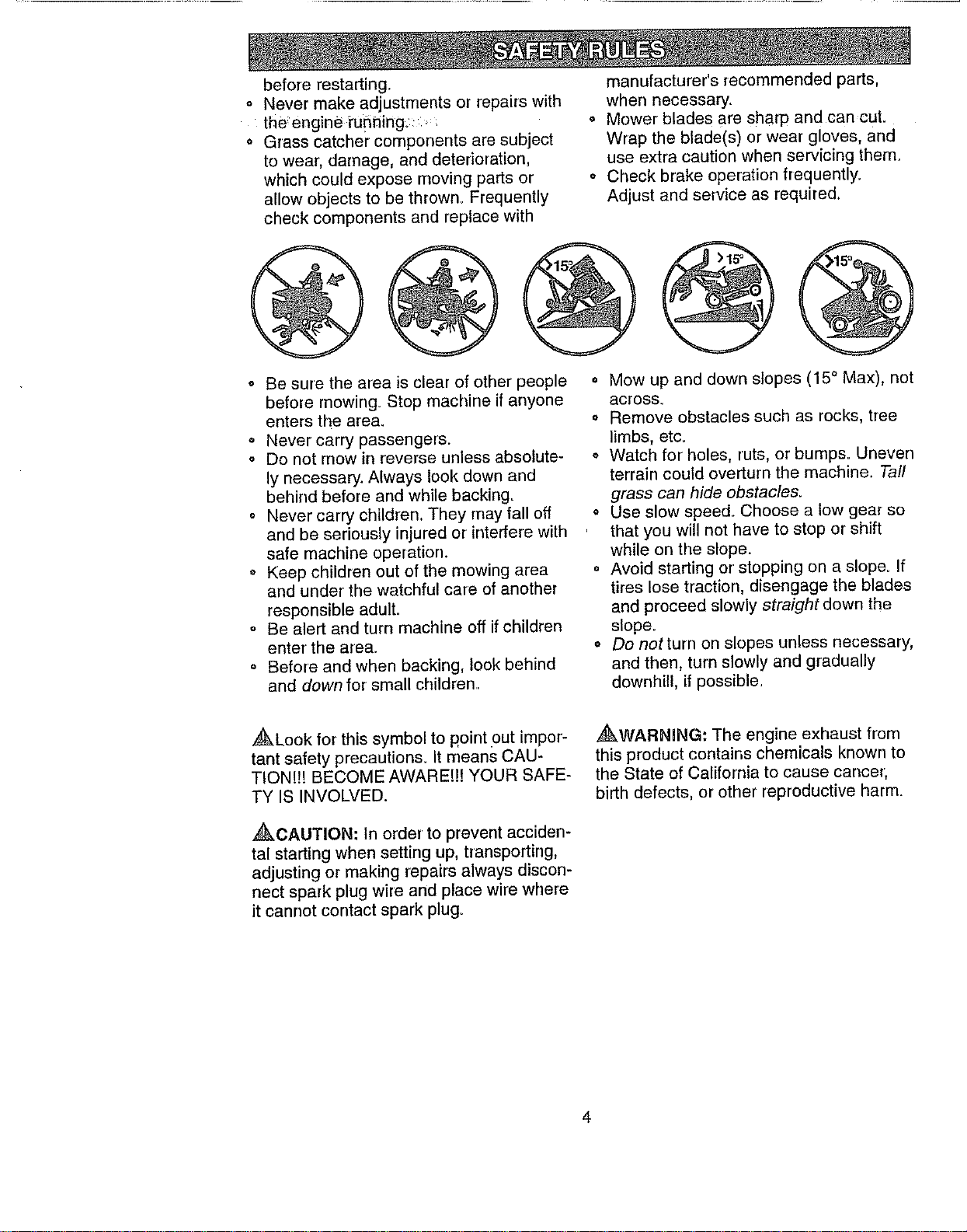
o Mow up and down slopes (15 ° Max), not
across.
o Remove obstacles such as rocks, tree
limbs, etc.
o Watch for holes, ruts, or bumps. Uneven
terrain could overturn the machine. Taft
grass can hide obstacles.
o Use slow speed° Choose a low gear so
that you will not have to stop or shift
while on the slope.
o Avoid starting or stopping on a slope. If
tires lose traction, disengage the blades
and proceed slowly straight down the
slope.
o Do notturn on slopes unless necessary,
and then, turn slowly and gradually
downhitl, if possible.
,g_Look for this symbol to point out impor-
tant safety precautions_ It means CAU-
TION!!! BECOME AWARE!!! YOUR SAFE-
TY IS INVOLVED.
Z_kCAUTION; In order to prevent acciden-
tal starting when setting up, transporting,
adjusting or making repairs always discon-
nect spark plug wire and place wire where
Jt cannot contact spark plugo
,_WARNJNG: The engine exhaust from
this product contains chemicals known to
the State of California to cause cancer,
birth defects, or other reproductive harm.
4
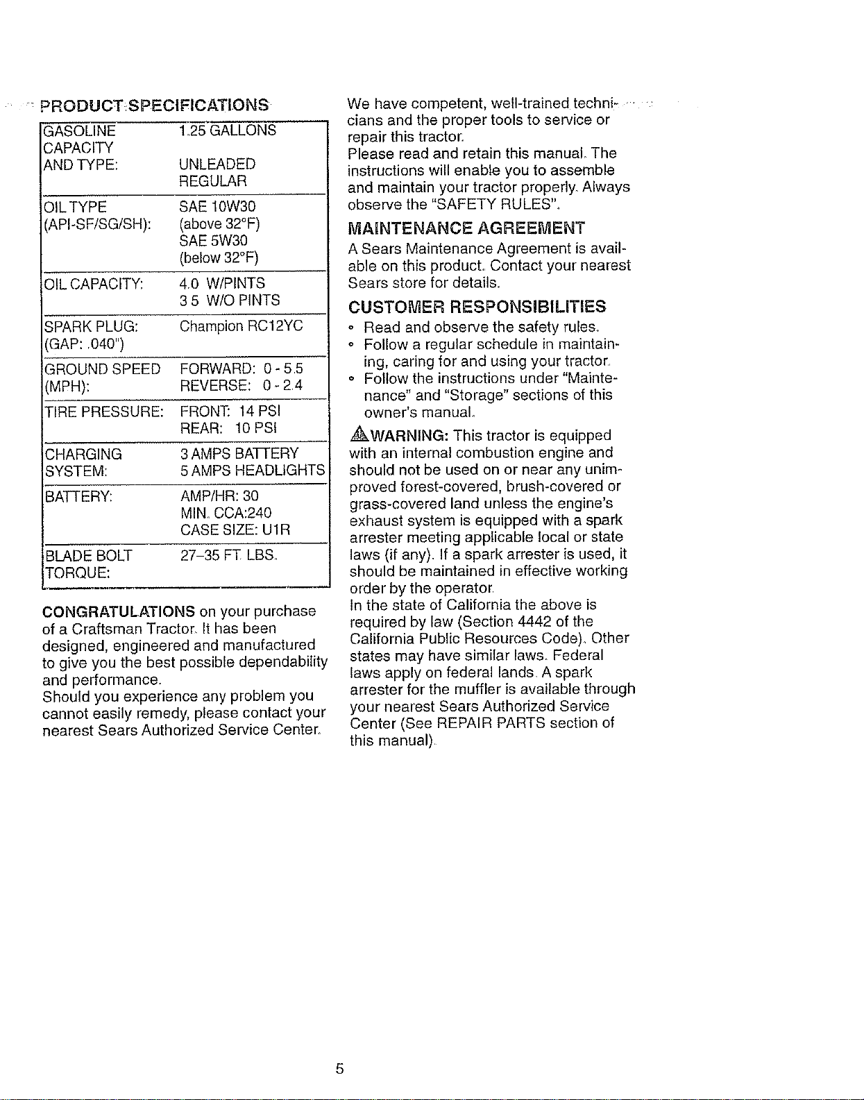
PRODUCT S PECIFICATI.ONS
GASOLINE 125 GALLONS
:APACITY
ND TYPE: UNLEADED
REGULAR
OIL TYPE SAE 10W30
_,PI-SF/SG/SH): (above 32°F)
SAE 5W30
(below 32°F)
OIL CAPACITY: 4r0 W/PINTS
3 5 W/O PINTS
SPARK PLUG: Champion RC12YC
GAP: .040")
GROUND SPEED FORWARD: 0- 5 5
(MPH): REVERSE: 0-24
TIRE PRESSURE: FRONT: 14 PSI
REAR: 10 PSI
CHARGING 3 AMPS BATTERY
SYSTEM: 5 AMPS HEADLIGHTS
BATTERY: AMP/HR: 30
MIN. CCA:240
CASE SIZE: U1R
BLADE BOLT 27-35 FT LBS.
TORQUE:
CONGRATULATIONS on your purchase
of a Craftsman Tractor It has been
designed, engineered and manufactured
to give you the best possible dependability
and performance.
Should you experience any problem you
cannot easily remedy, please contact your
nearest Sears Authorized Service Center.
We have competent, well-trained techni ....
clans and the proper tools to service or
repair this tractor.
Please read and retain this manual The
instructions will enable you to assemble
and maintain your tractor properly. Always
observe the "SAFETY RULES'L
MAINTENANCE AGREEMENT
A Sears Maintenance Agreement is avail-
able on this product,, Contact your nearest
Sears store for detail&
CUSTOMER RESPONSIBILITIES
o Read and observe the safety rules.
o Follow a regular schedule in maintain-
ing, caring for and using your tractor.
o Follow the instructions under "Mainte-
nance" and "Storage" sections of this
owner's manual
_WARNING: This tractor is equipped
with an internal combustion engine and
should not be used on or near any unim*
proved forest-covered, brush-covered or
grass-covered land unless the engine's
exhaust system is equipped with a spark
arrester meeting applicable local or state
laws (if any). If a spark arrester is used, it
should be maintained in effective working
order by the operator
tn the state of California the above is
required by law (Section 4442 of the
California Public Resources Code)_ Other
states may have similar laws. Federal
laws apply on federal lands. A spark
arrester for the muffler is available through
your nearest Sears Authorized Service
Center (See REPAIR PARTS section of
this manual).
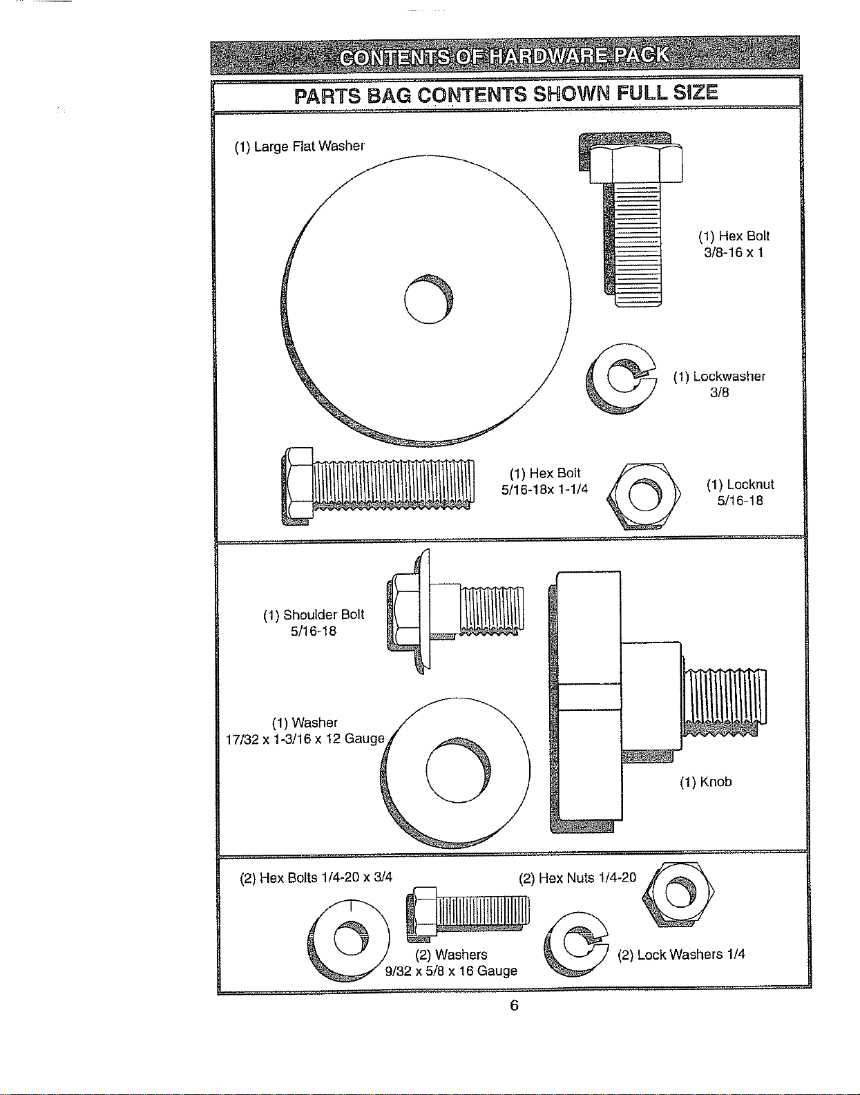
PARTS BAG CONTENTS SHOWN FULL SIZ_=
.. ..... ;,...... '. .
(1) Large Flat Washer
©
(1) Hex Bolt
3/8-16 x 1
(1) Lockwasher
3/8
(1) Hex Bolt
5/16-18x 1-1/4 _ (1) Lecknut
5/16-18
(1) Shoulder Bolt
5/16-18
(1) Washer
17/32 x 1-3/16 x 12 Gauge
©
(1) Knob
/32 x 5/8 x 16 Gauge
(2) Hex Bolts 1/4-20 x 3/4 (2) Hex Nuts 1/4-20
(2) Lock Washers 1/4
6
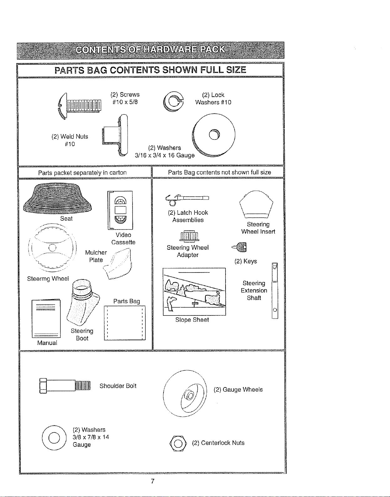
PARTS BAG CONTENTS SHOWN FULL SRZE
(2) Weld#!0 Nuts
(2) Screws _ (2) Lock
#10 x 5/8 _ Washers #10
(2) Washers I_
3/16 x 3/4 x 16 Gauge "_
Parts packet separately in carton Parts Bag contents not shown full size
Seat
_ y
Steermg Wheel
Steering
Boot
Manual
g&
C3
Video
Cassette
Mulcher ;<_ 1_7i
Plate :,' I
,f' 1
Parts Bag
i
i
i
i
i
I
(2) Latch Hook
Assemblies
Steering
Wheel Insert
Steering Wheel
Adapter
Slope Sheet
(2) Keys _.
Steering
Extension
Shaft
c
@
©
Shoulder Bolt
(2)Washers
3/8 x 7/8 x 14
Gauge
(2) Gauge Wheels
Q (2) Centedock Nuts
7
Your new tractor has been assembled at the factory with exception of those parts left
unassembled for shipping purposes. To ensure safe and proper operation of your tractor
all,parts:and;hardware.you assemble must be tightened securely. Use the c0rre_t tools
as necessary to insure proper tightness. Review the video cassette before you begin.
TOOLS REQUIRED FOR
ASSEMBLY
A socket wrench set will make assembly
easier. Standard wrench sizes you need
are listed below.
(1) 9/16',' wrench (1) 3/4" Socket w/
(2) 7/16' wrenches drive rachet
(2) 1/2" wrench (1) Phillips Screw-
(1) 3/4" wrench driver
(1) Utility knife (1) Tire pressure
(1)Pliers gauge
When right or left hand is mentioned in
this manual, it means, from your point of
view, when you are in the operating posi-
tion (seated behind the steering wheel).
TO REMOVE TRACTOR FROM
CARTON
UNPACK CARTON
° Remove all accessible loose parts and
parts boxes from shipping carton (See
page 6).
° Cut, from top to bottom, along lines on
all four corners of shipping carton, and
lay panels flat.
o Check for any additional loose parts or
boxes and remove.
BEFORE ROLLING TRACTOR OFF
SKiD
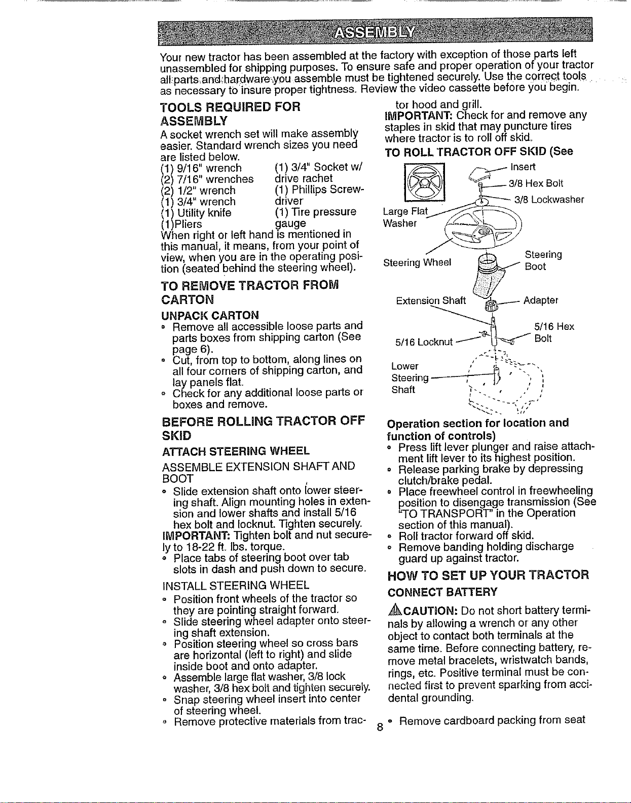
ATTACH STEERING WHEEL
ASSEMBLE EXTENSION SHAFTAND
BOOT
o Slide extension shaft onto lower steer-
ing shaft. Align mounting holes in exten-
sion and lower shafts and install 5/16
hex bolt and Iocknut. ]]ghten securely,
IMPORTANT" Tighten bolt and nut secure-
ly to 18-22 ft. Ibs. torque.
o Place tabs of steedng boot over tab
slots in dash arid push down to secure=
INSTALL STEERING WHEEL
o Position front wheels of the tractor so
they are pointing straight forward.
Slide steering wheel adapter onto steer-
ing shaft extension.
o Position steering wheel so cross bars
are horizontal (left to right) and slide
inside boot and onto adapter.
o Assemble large flat washer, 3/8 lock
washer, 3/8 hex bolt and tighten securely.
o Snap steering wheel insert into center
of steering wheel.
Remove protective materials from trac-
tor hood and grill.
IMPORTANT; Check for and remove any
staples in skid that may puncture tires
where tractor is to roll off skid.
TO ROLL TRACTOR OFF SKiD (See
_._._-Insert
_---3/8 Hex BoR
LargeFla_'_--__ 8 Coekwasher
Washer _9
_ Steering
Steering Wheel _ Boot
Extension_t.Shaft t_.---- Adapter
e _'_ "_knut "_*'_'_ 5/16 Hex
5/16 Lo Bolt
Lower / ;_ -.'-- - -
Steering ------"'7"-'_, _ °
Shaft "_.. ."
Operation section for location and
function of controls)
o Press lift lever plunger and raise attach-
ment lift lever to its highest position.
Release parking brake by depressing
clutch/brake pedal.
= Place freewheel control in freewheeling
position to disengage transmission (See
"TO TRANSPORT" in the Operation
section of this manual).
Roll tractor forward off skid.
o Remove banding holding discharge
guard up against tractor.
HOW TO SET UP YOUR TRACTOR
CONNECTBATTERY
_CAUTION: Do not short battery termi-
nals by allowing a wrench or any other
object to contact both terminals at the
same time. Before connecting battery, re-
move metal bracelets, wristwatch bands,
rings, etc. Positive terminal must be con-
nected first to prevent sparking from acci-
dental grounding.
8 ° Remove cardboard packing from seat
o Removecardboardpackingfromseat
panandliftseatpanto raisedposition.
o Openbatteryboxdoorandremovepro-
tectiveplastic.
o Removeterminalprotectivecapsand
discard..
,, Ifthisbatteryisputintoserviceafter
monthandyearindicatedonlabel(label
locatedbetweenterminals)chargebat-
teryforminimumofonehourat6-10
amps
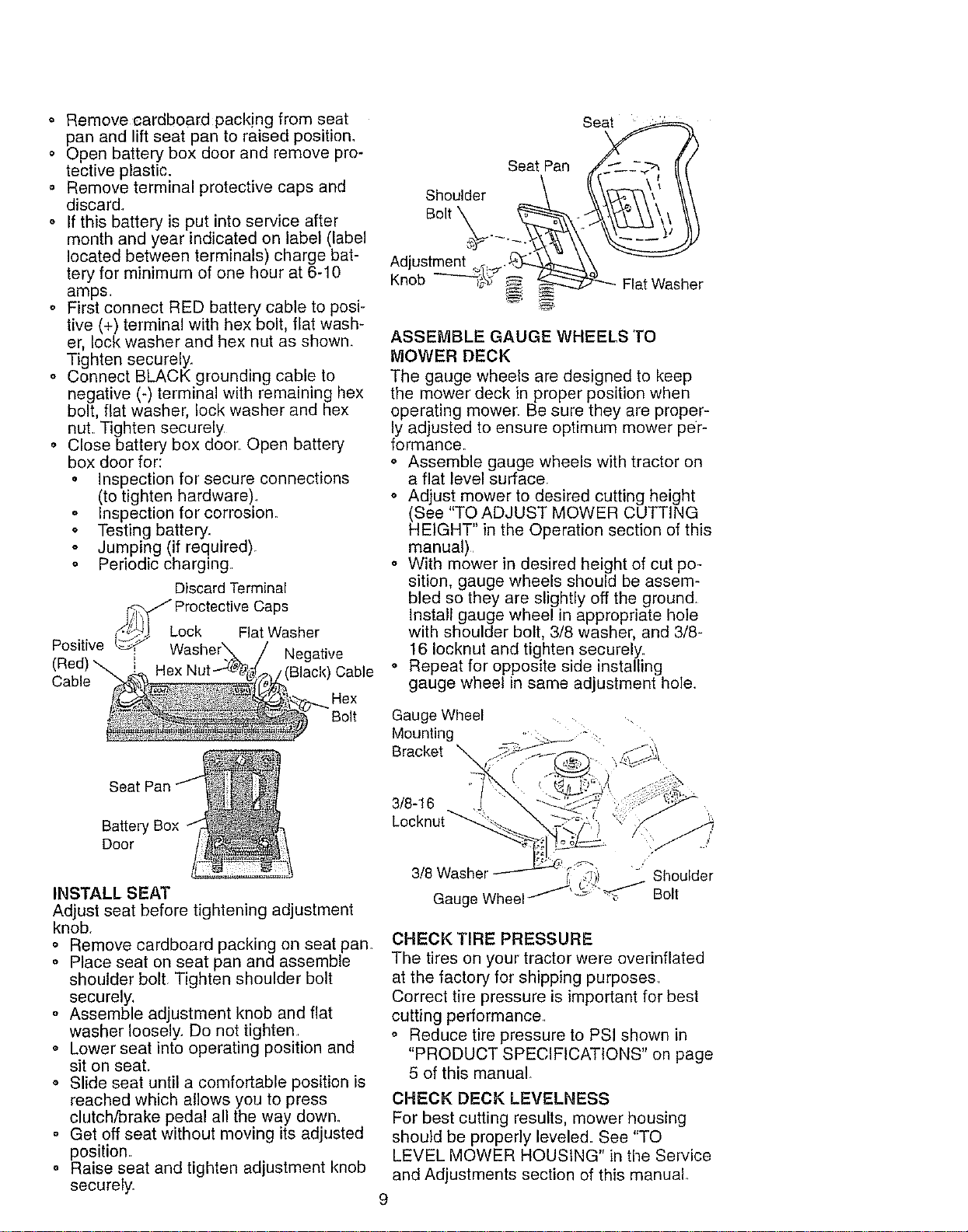
o FirstconnectREDbatterycabletoposi-
tive(+)terminalwithhexbolt,flatwash-
er,lockwasherandhexnutasshown.
Tightensecurely.
o ConnectBLACKgroundingcableto
negative(-)terminalwithremaininghex
bolt,fiatwasher,lockwasherandhex
nut.Tightensecurely
o Closebatteryboxdoor Openbattery
boxdoorfor:
• Inspection for secure connections
(to tighten hardware)
o Inspection for corrosion.
o Testing battery.
• Jumping (if required).
o Periodic charging.
Discard Terminal
_ Proctective Caps
Lock w
Positive t_'P,SJ Flat asher
(Red) _ i Negative
Cable / (I Cable
Rex
Bolt
Seat Pan _/___.-_'_f _
Shoulder \ 'k\-_"_\, ' \\
Bolt o - _'_'_\,_
Knob FlatWasher
ASSEMBLE GAUGE WHEELS TO
MOWER DECK
The gauge wheels are designed to keep
the mower deck in proper position when
operating mower. Be sure they are proper-
ly adjusted to ensure optimum mower per-
formance_
o Assemble gauge wheels with tractor on
a flat level surface,
o Adjust mower to desired cutting height
(See "TO ADJUST MOWER CUTTING
HEIGHT" in the Operation section of this
manual)
o With mower in desired height of cut po-
sition, gauge wheels should be assem-
bled so they are slightly off the ground.
Install gauge wheel in appropriate hole
with shoulder bolt, 3/8 washer, and 3/8-
16 Iocknut and tighten securely.
o Repeat for opposite side installing
gauge wheel in same adjustment hole.
Gauge Wheel ....
Mounting ,. _ .
Bracket
Seat Pan
Battery Box
Door
INSTALL SEAT
Adjust seat before tightening adjustment
knob.
° Remove cardboard packing on seat pan
o Place seat on seat pan and assemble
shoulder bolt Tighten shoulder bolt
securely.
o Assemble adjustment knob and flat
washer loosely. Do not tighten
,, Lower seat into operating position and
sit on seat.
,, Slide seat until a comfortable position is
reached which allows you to press
clutch/brake pedal all the way down.
o Get off seat without moving its adjusted
position
o Raise seat and tighten adjustment knob
securely.
3/8-16
Locknut _' ._
3/8 Washer ,_i) - Shoulder
Gauge Wheel/'_':''_ Bolt
CHECK TIRE PRESSURE
The tires on your tractor were overinflated
at the factory for shipping purposes.
Correct tire pressure is important for best
cutting performance.
o Reduce tire pressure to PSI shown in
"PRODUCT SPECIFICATIONS" on page
5 of this manual
CHECK DECK LEVELNESS
For best cutting results, mower housing
should be properly leveled. See "TO
LEVEL MOWER HOUSING" in the Service
and Adjustments section of this manual.
9
CHECKFORPROPERPOSITIONOF
ALL BELTS
Seethefiguresthatareshownfor replac-
ingmotionandmowerbladedrivebeltsin
theServiceandAdjustmentssec!oinof
thismanualVerifythatthebeltsare rout-
edcorrectly_
CHECK BRAKE SYSTEM
After you learn how to operate your trac-
tor, check to see that the brake is properly
adjusted° See "TO ADJUST BRAKE" in
the Service and Adjustments section of
this manual.
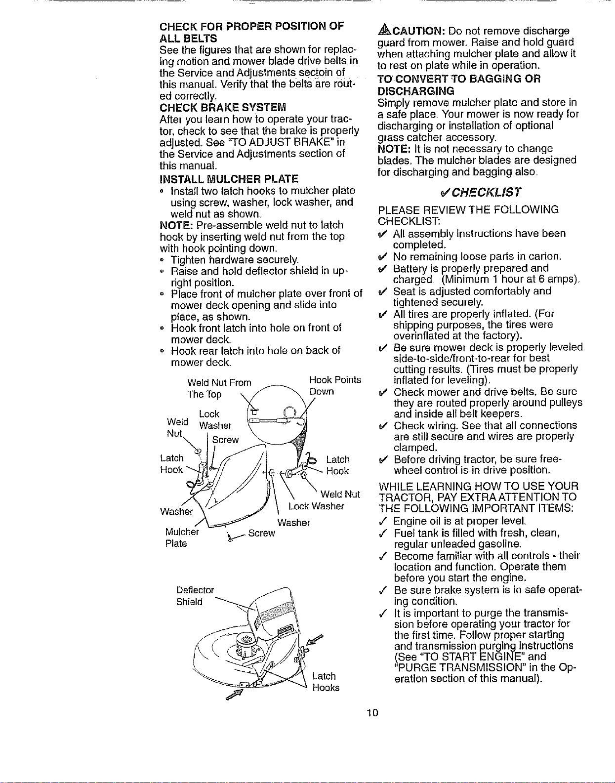
INSTALL MULCHER PLATE
= Install two latch hooks to mulcher plate
using screw, washer, lock washer, and
weld nut as shown_
NOTE: Pre-assemble weld nut to latch
hook by inserting weld nut from the top
with hook pointing down_
o Tighten hardware securely_
o Raise and hold deflector shield in up-
right position.
= Place front of mulcher plate over front of
mower deck opening and slide into
place, as shown.
° Hook front latch into hole on front of
mower deck.
o Hook rear latch into hole on back of
mower deck.
Weld Nut From Hook Points
The Top \ Down
Lock
Weld Washer
Nut
Screw
Latch Latch
Washer
Mulcher
Plate
Nut
Lock Washer
Washer
Screw
Deflector
Shield
Latch
Hooks
,_CAUTION: Do not remove discharge
guard from mower:. Raise and hold guard
when attaching mulcher plate and allow it
to rest on plate while in operation.
TO CONVERT TO BAGGING OR
DISCHARGING
Simply remove mulcher plate and store in
a safe place_ Your mower is now ready for
discharging or installation of optional
grass catcher accessory.
NOTE: It is not necessary to change
blades= The muloher blades are designed
for discharging and bagging also..
V'CHECKLiST
PLEASE REVIEW THE FOLLOWING
CHECKLIST:
e" All assembly instructions have been
completed.
e/ No remaining loose parts in carton.
v' Battery is properly prepared and
charged. (Minimum 1 hour at 6 amps)_
e,' Seat is adjusted comfortably and
tightened securely.
All tires are properly inflated. (For
shipping purposes, the tires were
overinflated at the factory)_
Be sure mower deck is properly leveled
side-to-side/front-to-rear for best
cutting result& (Tires must be properly
inflated for leveling).
e,' Check mower and drive belts. Be sure
they are routed properly around pulleys
and inside all belt keepers.
e/ Check wiring. See that all connections
are still secure and wires are properly
clamped_
e,' Before driving tractor, be sure free-
wheel control is in drive position°
WHILE LEARNING HOW TO USE YOUR
TRACTOR, PAY EXTRAATTENTION TO
THE FOLLOWING IMPORTANT ITEMS:
,/ Engine oil is at proper level.
J Fuel tank is filled with fresh, clean,
regular unleaded gasoline.
,/ Become familiar with all controls - their
location and function. Operate them
before you start the engine.
# Be sure brake system is in safe operat-
ing condition.
,/ It is important to purge the transmis-
sion before operating your tractor for
the first time. Follow proper starting
and transmission purging instructions
(See "TO START ENGINE" and
"PURGE TRANSMISSION" in the Op-
eration section of this manual).
10
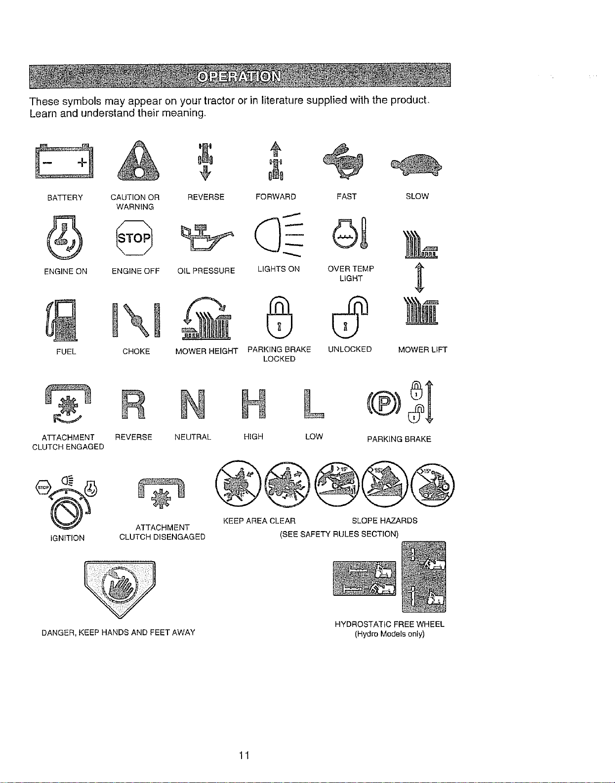
Thesesymbolsmayappearonyourtractororinliteraturesuppliedwiththe product,
Learnandunderstandtheirmeaning,
BATTERY CAUTION OR
WARNING
ENGINE ON ENGINE OFF
FUEL CHOKE
¢
REVERSE FORWARD FAST
OIL PRESSURE LIGHTS ON OVER TEMP
LIGHT
MOWER HEIGHT PARKING BRAKE UNLOCKED
LOCKED
SLOW
MOWER LIFT
A'FFACHMENT
CLUTCH ENGAGED
IGNITION
R N
REVERSE NEUTRAL
ATTACHMENT
CLUTCH DISENGAGED
N L o5;
HIGH LOW PARKING BRAKE
@@®@@
KEEP AREA CLEAR SLOPE HAZARDS
(SEE SAFETY RULES SECTION)
DANGER, KEEP HANDS AND FEET AWAY
HYDROSTATIC FREE WHEEL
(Hydro Models only)
11
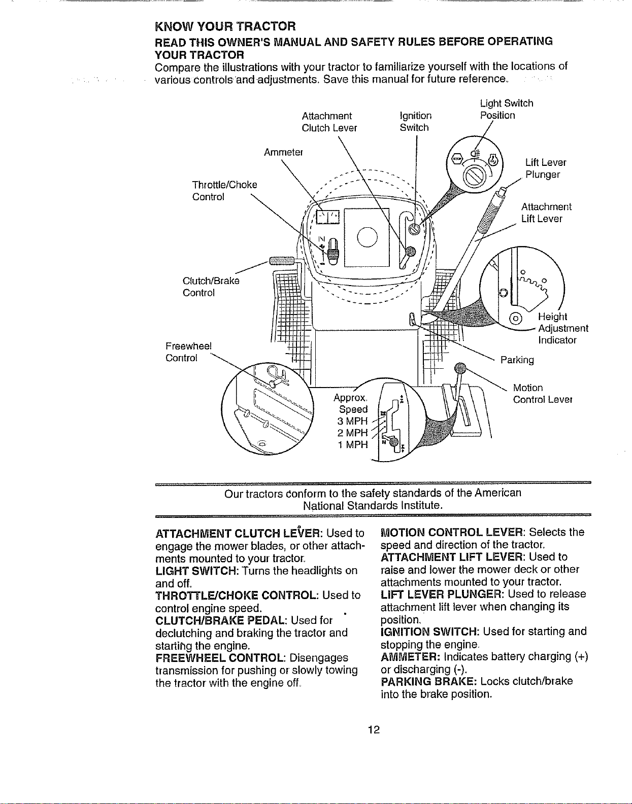
KNOW YOUR TRACTOR
READ THIS OWNER'S MANUAL AND SAFETY RULES BEFORE OPERATING
YOUR TRACTOR
Compare the illustrations with your tractor to familiarize yourself with the locations of
various controlsand-adjustment& Save this manual for future reference_
Attachment Ignition
Clutch Lever Switch
Light Switch
Position
Throttle/Choke
Control
Ammeter
Lift Lever
Plunger
Attachment
Lift Lever
Clutch/Brake
Control
Freewheel
Control
Approx
Speed
3 MPH /
2 MPH
1 MPH ...
Height
Adjustment
Indicator
Parking
_--. Motion
Control Lever
Our tractors conform to the safety standards of the American
National Standards Institute.
ATTACHMENT CLUTCH LE_fER: Used to
engage the mower blades, or other attach-
ments mounted to your tractor,
LIGHT SWITCH: Turns the headlights on
and off.
THROTTLE/CHOKE CONTROL: Used to
control engine speed.
CLUTCH/BRAKE PEDAL: Used for
declutching and braking the tractor and
startihg the engine.
FREEWHEEL CONTROL: Disengages
transmission for pushing or slowly towing
the tractor with the engine offu
MOTION CONTROL LEVER: Selects the
speed and direction of the tractor:
ATTACHMENT LIFT LEVER: Used to
raise and lower the mower deck or other
attachments mounted to your tractor.
LIFT LEVER PLUNGER: Used to release
attachment lift lever when changing its
position,
IGNITION SWITCH: Used for starting and
stopping the engine
AMMETER: Indicates battery charging (+)
or discharging (-)_
PARKING BRAKE: Locks clutch/brake
into the brake position.
12
_ hd:0peratienofanytractorcanresultinforeignobjectsthrownintothe
eyes,whichcanresultinsevereeyedamage.Alwayswearsafetyglasses
oreyeshieldswhileoperatingyourtractororperforminganyadjustmentsor
repairs.Werecommendawidevisionsafetymaskoverthespectacles,or
standardsafetyglasses.
HOW TO USE YOUR TRACTOR
Your tractor is equipped with an operator
presence sensing switch. When engine is
running, any attempt by the operator to
leave the seat without first setting the
parking brake will shut off the engine.
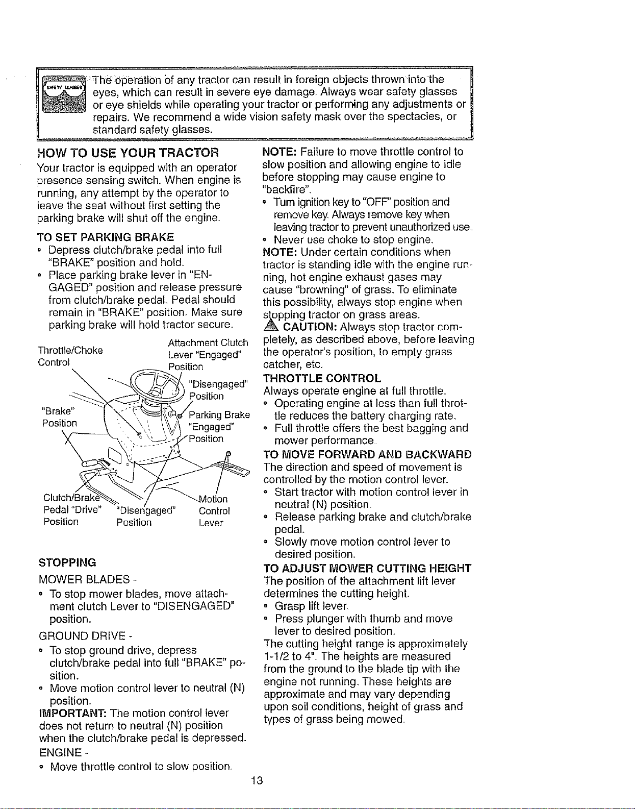
TO SET PARKING BRAKE
o Depress clutch/brake pedal into full
"BRAKE" position and hold
o Place parking brake lever in "EN-
GAGED" position and release pressure
from clutch/brake pedal Pedal should
remain in "BRAKE" position. Make sure
parking brake will hold tractor secure.
Attachment Clutch
Throttle/Choke Lever "Engaged"
Control Position
"Disengaged"
Position
"Brake" Brake
Position
J
"--"_'-qMotion
Pedal "Drive" ,gaged" Control
Position Position Lever
STOPPING
MOWER BLADES -
,, To stop mower blades, move attach-
ment clutch Lever to "DISENGAGED"
position_
GROUND DRIVE -
o To stop ground drive, depress
clutch/brake pedal into full "BRAKE" po-
sition.
o Move motion control lever to neutral (N)
position.
IMPORTANT: The motion control lever
does not return to neutral (N) position
when the clutch/brake pedal is depressed.
ENGINE -
,, Move throttle control to slow position.
NOTE: Failure to move throttle control to
slow position and allowing engine to idle
before stopping may cause engine to
"backfire"..
o Turn ignition key to "OFF" position and
remove key Always remove key when
leaving tractor to prevent unauthorized use.
• Never use choice to stop engine.
NOTE: Under certain conditions when
tractor is standing idle with the engine run-
ning, hot engine exhaust gases may
cause "browning" of grass. To eliminate
this possibility, always stop engine when
_pping tractor on grass areas.
CAUTION: Always stop tractor com-
pletely, as described above, before leaving
the operator's position, to empty grass
catcher, etc_
THROTTLE CONTROL
Always operate engine at full throttle
o Operating engine at less than full throt-
tie reduces the battery charging rate.
o Full throttle offers the best bagging and
mower performance
TO MOVE FORWARD AND BACKWARD
The direction and speed of movement is
controlled by the motion control lever
o Start tractor with motion control lever in
neutral (N) position.
,, Release parking brake and clutch/brake
pedal..
,, Slowly move motion control lever to
desired position.
TO ADJUST MOWER CUTTING HEIGHT
The position of the attachment lift lever
determines the cutting height.
o Grasp lift lever_
o Press plunger with thumb and move
lever to desired position.
The cutting height range is approximately
1-1/2 to 4". The heights are measured
from the ground to the blade tip with the
engine not running These heights are
approximate and may vary depending
upon soil conditions, height of grass and
types of grass being mowed.
13
o Theaveragelawnshouldbecutto
approximately2-1/2inchesduringthe
coolseasonandtoover3inchesduring
hotmonths.Forhealthierandbetter
Iooldnglawns,mowoftenandafter
moderategrowth.
° Forbestcuttingperformance,grass
over6inchesin heightshouldbe
mowedtwice.Makethefirstcutrelative-
lyhigh;thesecondtodesiredheight.
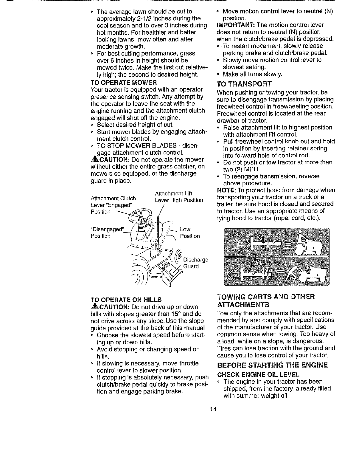
TO OPERATE MOWER
Your tractor is equipped with an operator
presence sensing switch. Any attempt by
the operator to leave the seat with the
engine running and the attachment clutch
engaged will shut off the engine.
o Select desired height of cuL
o Start mower blades by engaging attach-
ment clutch control
o TO STOP MOWER BLADES - disen=
_gage attachment clutch control°
CAUTION: Do not operate the mower
without either the entire grass catcher, on
mowers so equipped, or the discharge
guard in place.
Attachment Clutch
Lever "Engaged"
Position
Position
Attachrnent Lift
Lever High Position
..:::_..Low
Position
° Move motion control lever to neutral (N)
position.
IMPORTANT: The motion control lever
does not return to neutral (N) position
when the clutch/brake pedal is depressed.
, To restart movement, slowly release
parking brake and clutch/brake pedal.
o Slowly move motion control lever to
slowest setting.
= Make all turns slowly..
TO TRANSPORT
When pushing or towing your tractor, be
sure to disengage transmission by placing
freewheel contro! in freewheeling position.
Freewheel control is located at the rear
drawbar of tractor_
o Raise attachment lift to highest position
with attachment lift control=
o Pull freewheel control knob out and hold
in position by inserting retainer spring
into forward hole of control rod.
o Do not push or tow tractor at more than
two (2) MPH.
o To reengage transmission, reverse
above procedure.
NOTE: To protect hood from damage when
transporting your tractor on a truck or a
trailer, be sure hood is closed and secured
to tractor.. Use an appropriate rneans of
tying hood to tractor (rope, cord, etc.)=
Guard
TO OPERATE ON HILLS
,_CAUTION: Do not drive up or down
hills with slopes greater than 15 ° and do
not drive across any slope. Use the slope
guide provided at the back of this manual
• Choose the slowest speed before start-
ing up or down hills_
o Avoid stopping or changing speed on
hills_
o If slowing is necessary, move throttle
control lever to slower position.
° If stopping is absolutely necessary, push
clutch/brake pedal quickly to brake posi-
tion and engage parking brake.
TOWING CARTS AND OTHER
ATTACHMENTS
Tow only the attachments that are recom-
mended by and comply with specifications
of the manufacturer ofyour tractor..Use
common sense when towing, Too heavy of
a load, while on a slope, is dangerous.
Tires can lose traction with the ground and
cause you to lose control of your tractor.
BEFORE STARTING THE ENGIN _=
CHECK ENGINE OIL LEVEL
• The engine in your tractor has been
shipped, from the factory, already filled
with summer weight oil
14
o Check engine oil with tractor on level
ground
o Remove oil fill cap/dipstick and wipe
clean, reinsert the dipstick and screw
cap tight, wait for a few seconds,
remove and read oil level If necessary,
add oil until "FULL" mark on dipstick is
reached. Do not overfill.
o For cold weather operation you should
change oil for easier starting (See "OIL
VISCOSITY CHART" in the Mainte-
nance section of this manual).
o To change engine oil, see the Mainte-
nance section in this manual.
ADD GASOLINE
o Fill fuel tank. Use fresh, clean, regular
unleaded gasoline with a minimum of 87
octane. (Use of leaded gasoline will
increase carbon and lead oxide
deposits and reduce valve life). Do not
mix oil with gasoline. Purchase fuel in
quantities that can be used within 30
days to assure fuel freshness.
IMPORTANT: When operating in tempera-
tures below 32°F(0°C), use fresh, clean
winter grade gasoline to help insure good
,_d weather starting.
WARNING: Experience indicates that
alcohol blended fuels (called gasohol or
using ethanol or methanol) can attract
moisture which leads to separation and
formation of acids during storage Acidic
gas can damage the fuel system of an
engine while in storage. To avoid engine
problems, the fuel system should be emp-.
tied before storage of 30 days or longer.
Drain the gas tank, start the engine and let
it run until the fuel lines and carburetor are
empty. Use fresh fuel next season. See
Storage instructions for additional informa-
tion Never use engine or carburetor
cleaner products in the fuel tank or perma-
nent damage may occur.
,_CAUTION: Fill to bottom of gas tank
filler neck. Do not overfill Wipe off any
spilled oil or fuel. De not store, spill or use
gasoline near an open flame
TO START ENGINE
When starting the engine for the first time
or if the engine has run out of fuel, it will
take extra cranking time to move fuel from
the tank to the engine.
,, Be sure freewheel control is in the
transmission engaged position.
o Sit on seat in operating position, depress
clutch/brake pedal and set parking brake
° Place motion cQntrol Jever in neutral (N)
position.
o Move attachment clutch to "DISEN-
GAGED" position..
o Move throttle control to choke position.
NOTE: Before starting, read the warm and
cold starting procedures below_
• Insert key into ignition and turn key
clockwise to "START" position and
release key as soon as engine start&
Do not run starter continuously for more
than fifteen seconds per minute. If the
engine does not start after several
attempts, move throttle control to fast
position, wait a few minutes and try
again° tf engine still does not start,
move the throttle control back to the
choke position and retry.
WARM WEATHER STARTING (50 ° F and
above)
• When engine starts, move the throttle
control to the fast position_
o The attachments and ground drive can
now be used If the engine does not
accept the toad, restart the engine and
allow it to warm up for one minute using
the choke as described above.
COLD WEATHER STARTING ( 50 ° F and
below)
o When engine starts, allow engine to run
with the throttle control in the choke
position until the engine runs roughly,
then move throttle control to fast post-
tion. This may require an engine warm-
up period from several seconds to sev-
eral minutes, depending on the temper-
ature.
HYDROSTATIC TRANSMISSION WARM
UP
o Before driving the unit in cold weather,
the transmission should be warmed up
as follows:
o Be sure the tractor is on level groun&
o Place the motion control lever in neutral
Release the parking brake and let the
clutch/brake slowly return to operating
position°
o Allow one minute for transmission to
warm up. This can be done during the
engine warm up period.
• The attachments can also be used dur-
ing the engine warm-up period after the
transmission has been warmed up.
NOTE: At a high altitude (above 3000
feet) or in cold temperatures (below 32 F)
the carburetor fuel mixture may need to be
adjusted for best engine performance.
15
See"TOADJUSTCARBURETOR"inthe
ServiceandAdjustmentssectionofthis
manual.
_RGE TRANSMISS,ON "
CAUTJ0N. Never en{_age or disen'
gage freewheel lever while the engine is
running.
To ensure proper operation and perfor-
mance, it is recommended that the trans-
mission be purged before operating tractor
for the first time. This procedure will
remove any trapped air inside the trans-
mission which may have developed during
shipping of your tractor:
IMPORTANT: Should your transmission
require removal for service or replace-
ment, it should be purged after reinstalla-
tion before operating the tractor:
Place tractor safely on level surface with
engine off and parking brake set.
o Disengage transmission by placing free-
wheel control in freewheeling position
(See "TO TRANSPORT" in this section
of manual)..
= Sitting in the tractor seat, start engine.
After the engine is running, move throt-
tle control to slow position. With motion
control lever in neutral (N) position,
slowly disengage clutch/brake pedal.
Move motion control lever to full forward
position and hold for five (5) seconds.
Move lever to full reverse position and
hold for five (5) seconds. Repeat this
procedure three (3) times_
NOTE: During this procedure there will be
no movement of drive wheels. The air is
being removed from hydraulic drive sys-
tem.
o Move motion control lever to neutral (N)
position, Shut off engine and set parking
brake..
o Engage transmission by placing free-
wheel control in driving position (See
"TO TRANSPORT" in this section of
manual).
o Sitting in the tractor seat, start engine.
After the engine is running, move throt-
tle control to half (1/2) speed. With
motion control lever in neutral (N) posi-
tion, slowly disengage clutch/brake
pedal.
o Slowly move motion control lever for-
ward; after the tractor moves approxi-
mately five (5) feet, slowly move motion
control lever to reverse position. After
the tractor moves approximately five (5)
16
feet return the motion control lever to
the neutral (N) position. Repeat this pro-
cedure with the motion control lever
three (3) times.
o Your tractor is new purged and ready for
normal operation,.
MOWING TIPS
o
Q
o
q
Tire chains cannot be used when the
mower housing is attached to tractor:
Mower should be properly leveled for
best mowing performance_ See "TO
LEVEL MOWER HOUSING" in the
Service and Adjustments section of this
manual
The left hand side of mower should be
used for trimming
Drive so that clippings are discharged onto
the area that has been cut. Have the cut area
tothe rightof the tractor. This will result in a
more even distrib_on of clippings and more
uniform curing
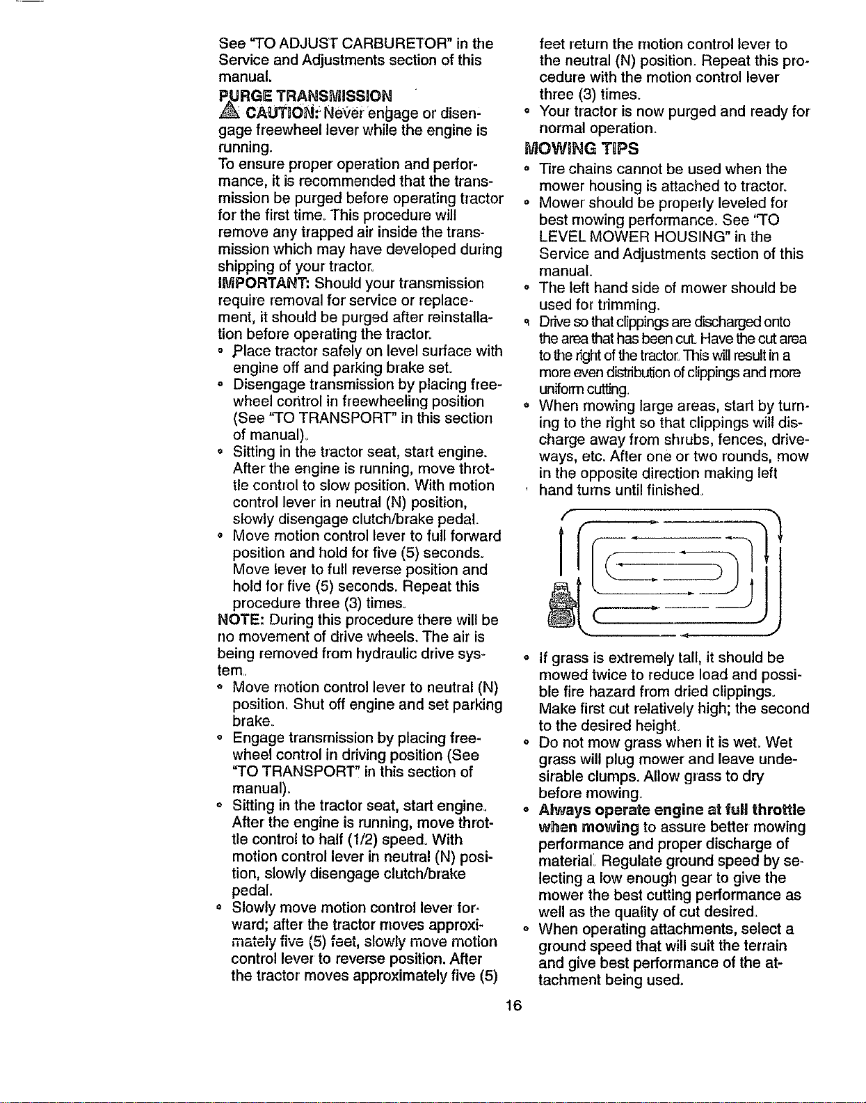
When mowing large areas, start by turn-
ing to the right so that clippings will dis-
charge away from shrubs, fences, drive-
ways, etc_ After one or two rounds, mow
in the opposite direction making left
hand turns until finished.
o if grass is extremely tall, it should be
mowed twice to reduce load and possi-
ble fire hazard from dried clippings.
Make first cut relatively high; the second
to the desired height.
o Do not mow grass when it is wet. Wet
grass will plug mower and leave unde-
sirable clumps. Allow grass to dry
before mowing_
o AJways operate engine at ful! throttle
when mowing to assure better mowing
performance and proper discharge of
material_ Regulate ground speed by se.
lecting a low enough gear to give the
mower the best cutting performance as
well as the quality of cut desired.
o When operating attachments, select a
ground speed that will suit the terrain
and give best performance of the at-
tachment being used.
MULCHqNG MOWING TgPS
IMP'ORTAhT: Fo_ I_est_performance, keep
mower housing {ree of built-up grass and
trash Clean after each use.
o The special mulching blade will recut
the grass clippings many times and
reduce them in size so that as they fall
onto the lawn they will disperse into the
grass and not be noticed Also, the
mulched grass will biodegrade quickly
to provide nutrients for the lawn. Always
mulch with your highest engine (blade)
speed as this will provide the best recut-
ting action of the blades.
o Avoid cutting your lawn when it is wet
Wet grass tends to form clumps and
interferes with the mulching action. The
best time to mow your lawn is the early
afternoon At this time the grass has
dried and the newly cut area will not be
exposed to the direct sun
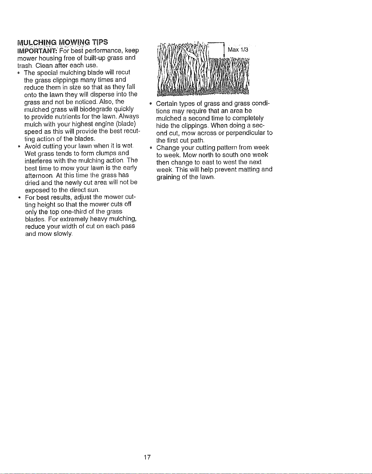
• For best results, adjust the mower cut-
ting height so that the mower cuts off
only the top one-third of the grass
blades For extremely heavy mulching,
reduce your width of cut on each pass
and mow slowly.
Max 1/3
Certain types of grass and grass condi-
tions may require that an area be
mulched a second time to completely
hide the clippings When doing a sec-
ond cut, mow across or perpendicular to
the first cut path.
Change your cutting pattern from week
to week. Mow north to south one week
then change to east to west the next
week This will help prevent matting and
graining of the lawn_
17
CUSTOMER RESPGNSaBILITIES
MAINTENANCE SCHEDULE __o _ ._,_"
FiLL iN DATES J__ERV___,_
AS YOU COMPLETE
REGULAR,SERVICE ATES
Check Brake Operation _#' _'
Check Tire Pressure _'
Check Operator Presence and
T Interlock Systems _#'
AR Check for Loose Fasteners .... _J' ....... _'7 _'
Sharpe_Replece Mower Blades Q_,#'.
_] Lub dcat'On C_art _
Check Battery Level
R Clean Battery and Terminals/Recharge _
Check Transaxle Goofing
Adjust Blade Belt(s) Tension
Adjust Motion Drive Belt(s) Tension
E
N
I
Check Engine Oil Level
i Change Engine Oil
Clean Air Filter
Clean Air Screen
Inspect Muffler/Spark A_rester
Replace Oil Filter (if equipped)
Clean Engine Cooling Fins
Replace Spark Plug
Replace Air Filter Paper Cartridge
Replace Fuel Filter
_2
V'
e/ V'
iv"
1 - Change more often when operating under a he_ W _oad or in high ambient lampor_tutes 5 - If equipped with adjustable system,
2 - Service more often when operating in dirty or dusty conditions
3 - if equipped with oi_ggor, char_ge oil every 50 hours
4 - Replace blades more orlon when mowing In sandy soil
GENERAL RECONIVlENDATIONS
The warranty on this tractor does not cover
items that have been subjected to operator
abuse or negligence. To receive full value
from the warranty, operator must maintain
tractor as instructed in this manual Some
adjustments will need to be made periodi-
cally to properly maintain your tractor.
All adjustments in the Service and
Adjustments section of this manual should
be checked at least once each season.
* Once a year you should replace the
spark plug, clean or replace air filter, and
check blades and belts for wear. A new
spark plug and clean air filter assure
proper air-fuel mixture and help your
engine run better and last longer.
BEFORE EACH USE
= Check engine oil level.
= Check brake operation°
o Check tire pressure°
o Check operator presence and interlock
systems for' proper operation.
o Check for loose fasteners.
6 - Not roquged il equipped with malrltonance-freo baUary
7 - 33ghtert bent axle plvol bog to 35 it ribs maximum
Do not ov_rllgh_en
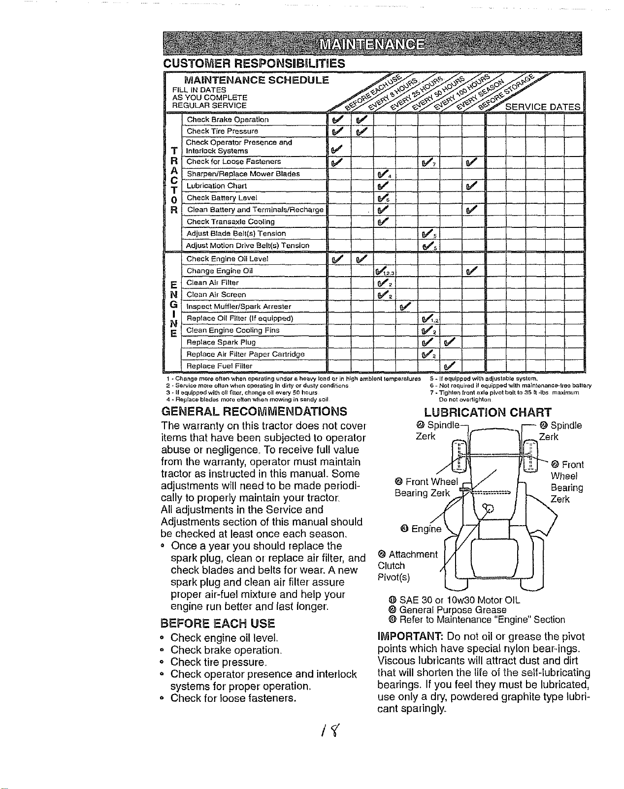
LUBRiCATiON CHART
O S O Spindle
Zerk Zerk
Front
Wheel
O Front Wheel
Beadng
Bearing Zerk Zerk
O
Attachment
Clutch
Pivot(e)
O SAE 30 or 10w30 Motor OIL
General Purpose Grease
O Refer to Maintenance "Engine" Section
INIPORTANT: Do not oil or grease the pivot
points which have special nylon bear-ings.
Viscous lubricants will attract dust and dirt
that will sho_en the life of the self-lubricating
bearings. If you feel they must be lubricated,
use only a dry, powdered graphite type lubri-
cant sparingly
TRACTOR
Alwaysobservesafetyruleswhenper-
forminganymaintenance_
BRAKEOPERATION
Iftractorrequiresmorethansix (6)feet
stoppingdistanceat highspeedinhighest
gear,thenbrakemustbeadjusted.(See
"TOADJUSTBRAKE"intheServiceand
Adjustmentssectionofthismanual).
TIRES
o Maintainproperairpressurein alltires
(See"PRODUCTSPECIFICATIONS"
onpage5ofthismanual)
o Keeptiresfreeof gasoline,oil,orinsect
controlchemicalswhichcanharmrub-
ber.
o Avoidstumps,stones,deepruts,sharp
objectsandotherhazardsthatmay
causetiredamage.
NOTE:Tosealtirepuncturesandprevent
flattiresduetoslowleaks,tiresealant
maybepurchasedfromyourlocalparts
dealer.Tiresealantalsopreventstiredry
rotandcorrosion,
BLADECARE
Forbestresultsmowerbladesmustbe
keptsharp.Replacebentordamaged
blades.
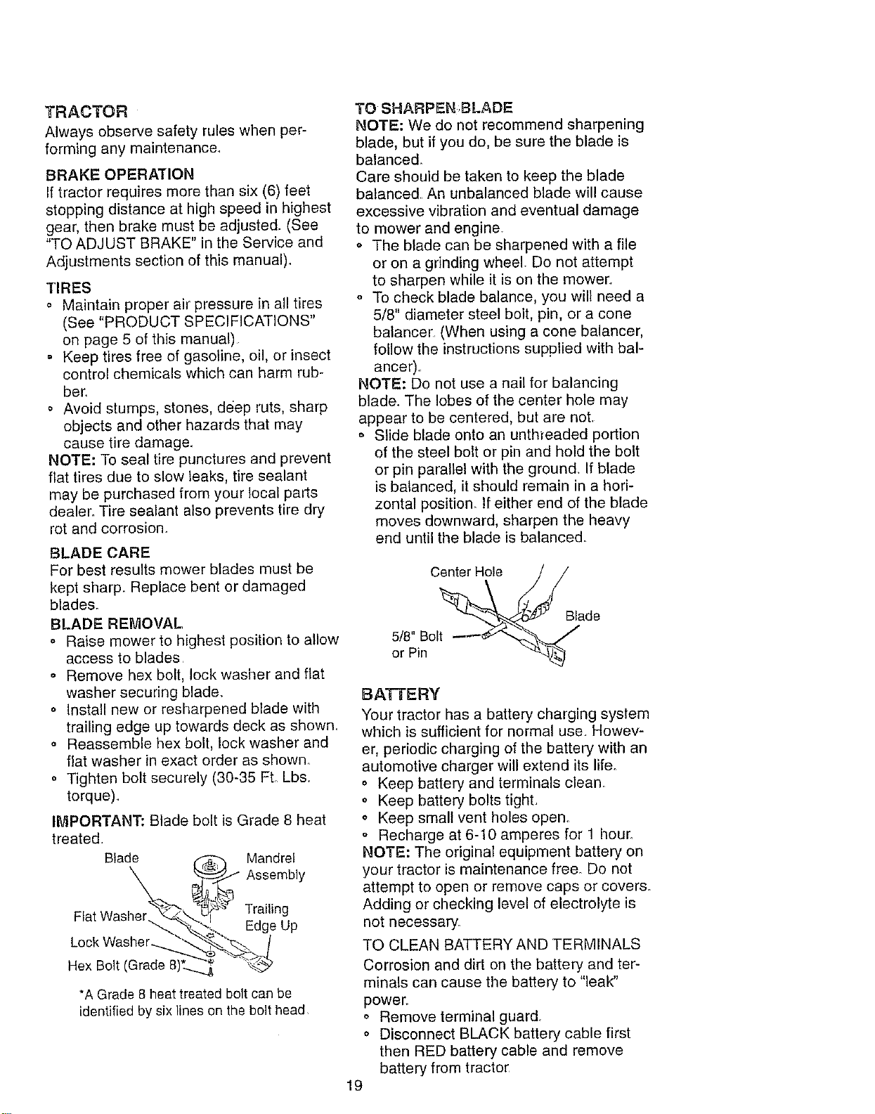
BLADEREMOVAL
o Raisemowertohighestpositionto allow
accessto blades
o Removehexbolt,lockwasherandflat
washersecuringblade°
° Installneworresharpenedbladewith
trailingedgeuptowardsdeckasshown.
o Reassemblehexbolt,lockwasherand
flat washer in exact order as shown_
o Tighten bolt securely (30-35 Ft. Lb&
torque).
IMPORTANT: Blade bolt is Grade 8 heat
treated
Blade f-_ Mandrel
X _._ Assembly
-._._ _"_:._' ,,
Flat Washer_'_ & Tra,hng
"_..._... _-ageup
Lock Washe r-__:>_/
Hex Bolt (Grade 8)t._.._ _...._b
*A Grade 8 heat treated bolt can be
identified by six lines on the bolt head
TO SHARPEN ;BLADE
NOTE: We do not recommend sharpening
blade, but if you do, be sure the blade is
balanced.
Care should be taken to keep the blade
balanced. An unbalanced blade will cause
excessive vibration and eventual damage
to mower and engine.
,, The blade can be sharpened with a file
or on a grinding wheel. Do not attempt
to sharpen while it is on the mower..
° To check blade balance, you will need a
5/8" diameter steel bolt, pin, or a cone
balancer (When using a cone balancer,
follow the instructions supplied with bal-
ancer)..
NOTE: Do not use a nail for balancing
blade. The lobes of the center hole may
appear to be centered, but are not.
o Slide blade onto an unth_eaded portion
of the steel bolt or pin and hold the bolt
or pin parallel with the ground. If blade
is balanced, it should remain in a hori-
zontal position. If either end of the blade
moves downward, sharpen the heavy
end until the blade is balanced.
Center Hole
5/8" Bolt
or Pin
Blade
BATTERY
Your tractor has a battery charging system
which is sufficient for normal use Howev-
er, periodic charging of the battery with an
automotive charger will extend its life.
o Keep battery and terminals clean.
o Keep battery bolts tight.
,' Keep small vent holes open.
° Recharge at 6-10 amperes for 1 hour.
NOTE: The original equipment battery on
your tractor is maintenance free. Do not
attempt to open or remove caps or covers.
Adding or checking level of electrolyte is
not necessary.
TO CLEAN BATTERY AND TERMINALS
Corrosion and dirt on the battery and ter-
minals can cause the battery to "leak"
power..
,, Remove terminal guard.
o Disconnect BLACK battery cable first
then RED battery cable and remove
battery from tractor
19
o Rinsethebatterywithplainwaterand
dry.
o Cleanterminalsandbatterycableends
withwirebrushuntilbright.
o Coattermnalswithgreaseorpetroleum
jelly.
° Reinstallbattery(See"CONNECTBAT-
TERY"intheAssemblysectionofthis
manual).
V-BELTS
CheckV-beltsfordeteriorationandwear
after100hoursofoperationandreplaceif
necessary.Thebeltsarenotadjustable.
Replacebeltsif theybeginto slipfrom
wear.
TRANSAXLE COOLING
Thetransmissionfanandcoolingfins
shouldbe keptcleantoassureproper
cooling_
Donotattempttocleanfanortransmis-
sionwhileengineisrunningorwhilethe
transmissionishoL
° Inspectcoolingfanto besurefan
bladesareintactandclean.
o Inspectcoolingfinsfordirt,grassclip-
pingsandothermaterial&Toprevent
damageto seals,donotusecom-
pressedairorhighpressuresprayerto
cleancoolingfins.
TRANSAXLE PUMP FLUID
The transaxle was sealed at the factory
and fluid maintenance is not required for
the life of the transaxle_ Should the
transaxle ever leak or' require servicing,
contact your nearest authorized service
center.
ENGINE
LUBRICATION
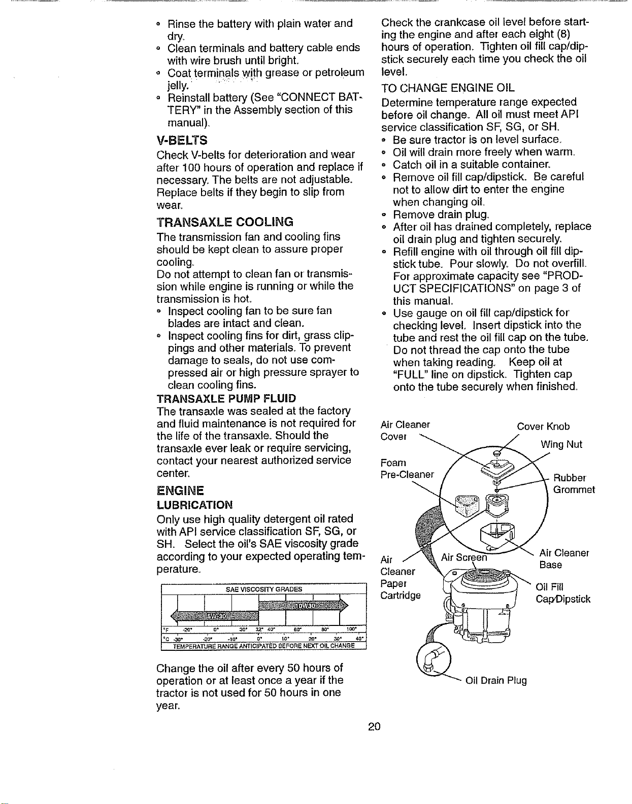
Only use high quality detergent oil rated
with API service classification SF, SG, or
SH. Select the oil's SAE viscosity grade
according to your expected operating tem-
perature=
SAE VISCOSITY GRADES
J 1 ! ' '
F *20 ° 0, ,30 32 • 40" 60- 8Q" 100"
=c&- -2_" -1_' ;" 1'o, _- _. &'
TEMPERATURE RANGE ANTICIPATED EEFORE NEXT OIL CHANGE
Check the crankcase oil level before start-
ing the engine and after each eight (8)
hours of operation. Tighten oil fill cap/dip-
stick securely each time you check the oil
level,
TO CHANGE ENGINE OIL
Determine temperature range expected
before oil change. All oil must meet API
service classification SF, SG, or SH.
o Be sure tractor is on level surface_
o Oil will drain more freely when warm.
= Catch oil in a suitable container°
o Remove oil fill cap/dipstick. Be careful
not to allow dirt to enter the engine
when changing oil
o Remove drain plug.
o After oil has drained completely, replace
oil drain plug and tighten securely.
o Refill engine with oil through oil fil! dip-
stick tube. Pour slowly. Do not overfill.
For approximate capacity see "PROD-
UCT SPECIFICATIONS" on page 3 of
this manual
= Use gauge on oil fill cap/dipstick for
checking level. Insert dipstick into the
tube and rest the oil fill cap on the tube.
Do not thread the cap onto the tube
when taking reading° Keep oil at
"FULU' line on dipstick. Tighten cap
onto the tube securely when finished=
Air Cleaner Cover Knob
Cover
Wing Nut
Foam
Pre-Cleaner Rubber'
Grommet
Air Cleaner
Air Base
Cleaner
Paper Oil Fill
Cartridge CaFDipstic k
Change the oil after every 50 hours of
operation or at least once a year if the
tractor is not used for 50 hours in one
year.
Oil Drain Plug
2O
CLEANAIR ,CREEN
Air screen must be kept free of dirt and
chaff to prevent engine damage from over-
heating_ Clean with a wire brush or com-
pressed air to remove dirt and stubborn
dried gum fibers,
AIR FILTER
Your engine will not run properly using a
dirty air filter Clean the foam pre-cleaner
after every 25 hours of operation or every
season. Service paper cartridge every
100 hours of operation or every season,
whichever occurs first
Service air cleanel more often under dusty
conditions.
o Remove knob and cover
o Remove wing nut and air cleaner from
base.
TO SERVICE PRE-CLEANER
o Slide foam pre-cleaner off cartridge.
Wash it in liquid detergent and water.
o Squeeze it dry in a clean cloth. Allow it
to dry.
o Saturate it in engine oil Wrap it in
clean, absorbent cloth and squeeze to
remove excess oil.
TO SERVICE CARTRIDGE
,, Replace a dirty, bent, or damaged car-
tridge.
NOTE: Do not wash the paper cartridge
or use pressurized air, as this will damage
the cartridge.
o Reinstall the pre-cleaner (cleaned
and oiled) over the paper car-
tridge.
o Reassemble air cleaner, wing nut,
cover and tighten knob securely.
CLEAN AIR INTAKE/COOLING AREAS
To insure proper cooling, make sure the
grass screen, cooling fins, and other
external surfaces of the engine are kept
clean at all time&
Every 100 hours of operation (more often
under extremely dusty, dirty conditions),
remove the blower housing and other
cooling shrouds. Clean the cooling fins
and external surfaces as necessary Make
sure the cooling shrouds are reinstalle&
NOTE: Operating the engine with a
blocked grass screen, dirty or plugged
cooling fins, and/or cooling shrouds re-
moved will cause engine damage due to
overheating°
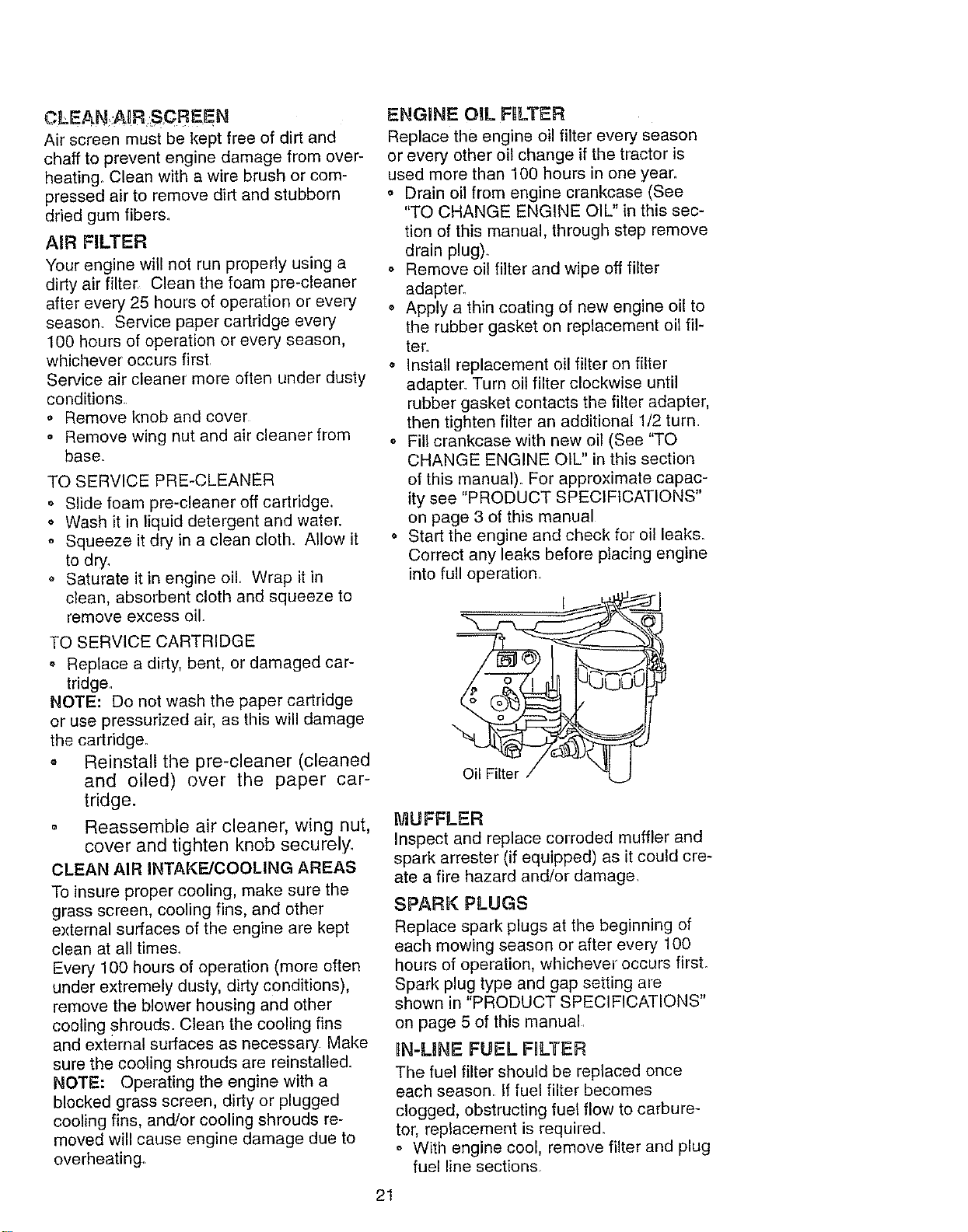
ENGINE OIL F_LTER
Replace the engine oil filter every season
or every other oil change if the tractor is
used more than 100 hours in one year.
o Drain oil from engine crankcase (See
"TO CHANGE ENGINE OIL" in this sec-
tion of this manual, through step remove
drain plug)..
,, Remove oil filter and wipe off filter
adapter.
o Apply a thin coating of new engine oil to
the rubber gasket on replacement oil fil-
ter..
• Install replacement oil filter on filter
adapter. Turn oil filter clockwise until
rubber gasket contacts the filter adapter,
then tighten filter an additional 1/2 turn
o Fill crankcase with new oil (See "TO
CHANGE ENGINE OIL" in this section
of this manual). For approximate capac-
ity see "PRODUCT SPECIFICATIONS"
on page 3 of this manual
o Start the engine and check for oil leaks.
Correct any leaks before placing engine
into full eperation.
MUFFLER
Inspect and replace corroded muffler and
spark arrester (if equipped) as it could cre-
ate a fire hazard and!or damage_
SPARK PLUGS
Replace spark plugs at the beginning of
each mowing season or after every 100
hours of operation, whichever occurs first.
Spark plug type and gap setting are
shown in "PRODUCT SPECIFICATIONS"
on page 5 of this manual.
IN-LINE FUEL FRLTER
The fuel filter should be replaced once
each season, if fuel filter becomes
clogged, obstructing fuel flow to carbure-
tor, replacement is required.
,, With engine cool, remove filter and plug
fuel line sections
21
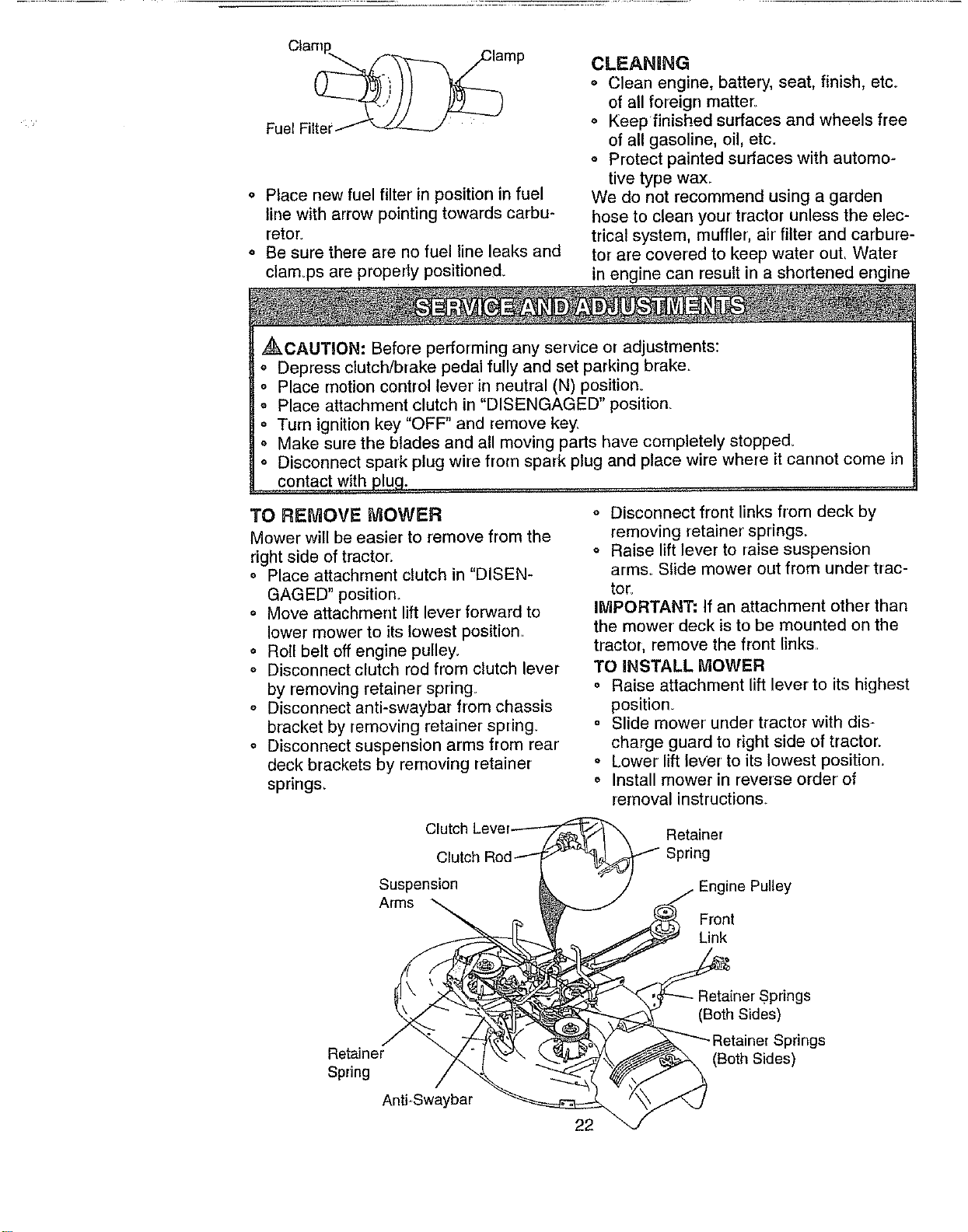
o Placenewfuelfilterinpositioninfuel
linewitharrowpointingtowardscarbu-
retor.
o Besuretherearenofuel lineleaksand
clamopsareproperlypositioned°
CLEANING
° Cleanengine, battery, seat, finish, etc_
of all foreign matter:.
o Keep finished surfaces and wheels free
of all gasoline, oil, etc.
o Protect painted surfaces with automo-
tive type wax.
We do not recommend using a garden
hose to clean your tractor unless the elec-
trical system, muffler, air filter and carbure-
tor are covered to keep water out, Water
in engine can result in a shortened engine
,_CAUTION: Before performing any service or adjustments:
o Depress clutch/brake pedal fully and set parking brake°
o Place motion control lever in neutral (N) position°
o Place attachment clutch in "DISENGAGED" position.
o Turn ignition key "OFF" and remove key.
o Make sure the blades and all moving parts have completely stopped.
o Disconnect spark plug wire from spark plug and place wire where it cannot come in
contact with plug.
3"0 REMOVE MOWER
Mower will he easier to remove from the
right side of tractor:
o Place attachment clutch in "DISEN-
GAGED" position,.
o Move attachment lift lever' forward to
lower mower to its lowest position.
• Roll belt off engine pulley,
= Disconnect clutch rod from clutch lever
by removing retainer spring
o Disconnect anti-swaybar from chassis
bracket by removing retainer spring.
o Disconnect suspension arms from rear
deck brackets by removing retainer
spring&
o Disconnect front links from deck by
removing retainer spring&
o Raise lift lever to raise suspension
arms° Slide mower out from under trac-
tor.
IMPORTANT: If an attachment other than
the mower deck is to be mounted on the
tractor, remove the front links,
TO INSTALL MOWER
o Raise attachment lift lever to its highest
position.
o Slide mower under tractor with dis-
charge guard to right side of tractor.
o Lower lift lever to its lowest position.
o Install mower in reverse order of
removal instructions.
Clutch
Suspension
Arms
Retainer
Engine Pulley
Front
Link
Retainer
Spring
Anti-Swaybar
22
(Both Sides)
prings
(Both Sides)
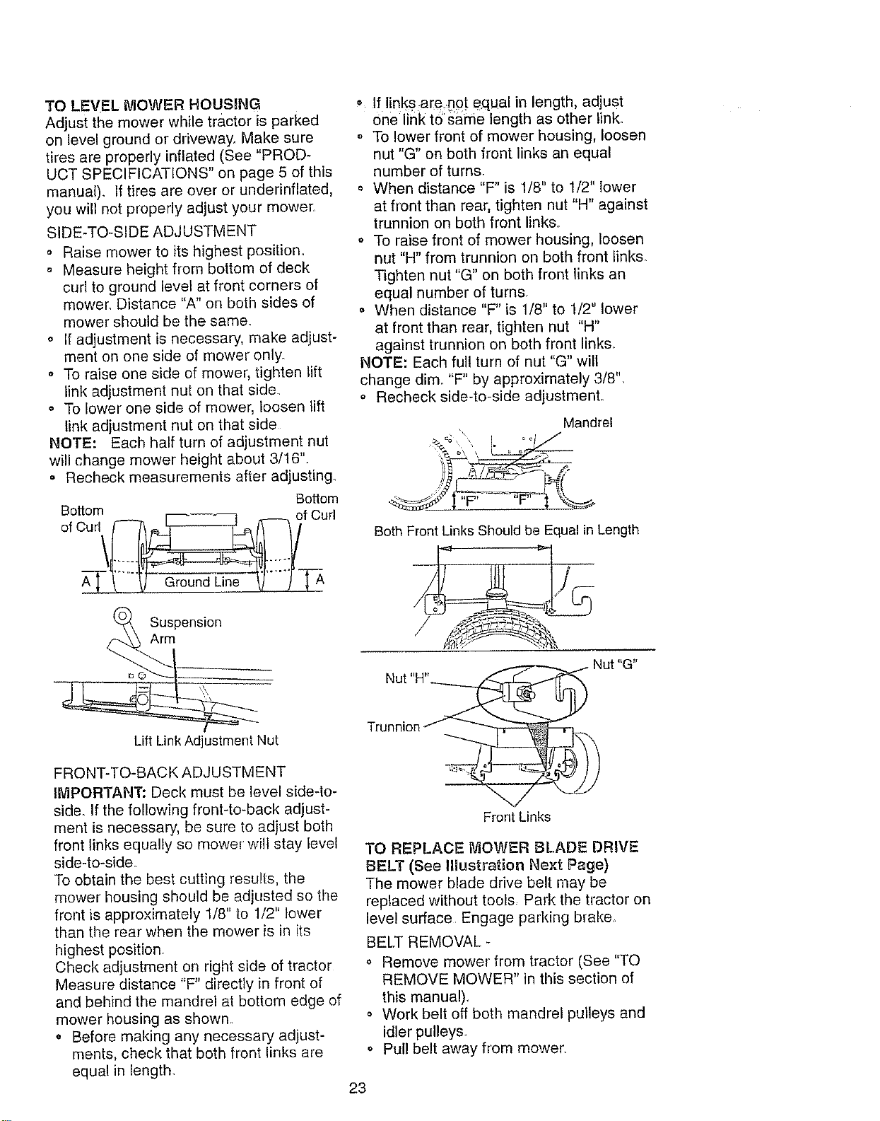
TO LEVEL MOWER HOUSING
Adjust the mower while tractor is parked
on level ground or driveway. Make sure
tires are properly inflated (See "PROD-
UCT SPECIFICATIONS" on page 5 of this
manual). If tires are over or underinflated,
you will not properly adjust your mower,
SIDE-TO-SIDE ADJUSTMENT
Raise mower to its highest position.
o Measure height from bottom of deck
curl to ground level at front corners of
mower Distance "A" on both sides of
mower should be the same.
o If adjustment is necessary, make adjust-
ment on one side of mower only.
,, To raise one side of mower, tighten lift
link adjustment nut on that side
° To lower one side of mower, loosen lift
link adjustment nut on that side
NOTE: Each half turn of adjustment nut
will change mower height about 3/16".
• Recheck measurements after adjusting.
Bottom
Bottom r_ _ of Curl
Suspension
Arm
• If links,are,_npt equal in length, adjust
one link tosame length as other link.
o To lower front of mower housing, loosen
nut "G" on both front links an equal
number of turns.
When distance "F" is 1/8" to 1/2" lower
at front than rear, tighten nut "H" against
trunnion on both front links.
• To raise front of mower housing, loosen
nut "H" from trunnion on both front links.
Tighten nut "G" on both front links an
equal number of turns.
• When distance "F" is 1/8" to 1/2" lower
at front than rear, tighten nut "H"
against trunnion on both front link&
NOTE: Each full turn of nut "G" will
change dim. "F" by approximately 3/8".
o Recheck side-to-side adjustmenL
Mandrel
Both Front Links Should be Equal in Length
Nut "H".
Lift Link Adjustment Nut
FRONT-TO-BACK ADJUSTMENT
IMPORTANT: Deck must be level side4o-
side. If the following front-to-back adjust-
ment is necessary, be sure to adjust both
front links equally so mower will stay level
side-to-side.
To obtain the best cutting results, the
mower housing should be adjusted so the
front is approximately 1/8" to 1/2" lower
than the rear when the mower is in its
highest position.
Check adjustment on right side of tractor
Measure distance "F" directly in front of
and behind the mandrel at bottom edge of
mower housing as shown
o Before making any necessary adjust-
ments, check that both front links are
equal in length.
Front Links
TO REPLACE MOWER BLADE DRIVE
BELT (See Illustration Next Page)
The mower blade drive belt may be
replaced without tools Park the tractor on
level surface Engage parking brake
BELT REMOVAL -
', Remove mower from tractor (See "TO
REMOVE MOWER" in this section of
this manual),
o Work belt off both mandrel pulleys and
idler pulleys.,
o Pull belt away from mower
23
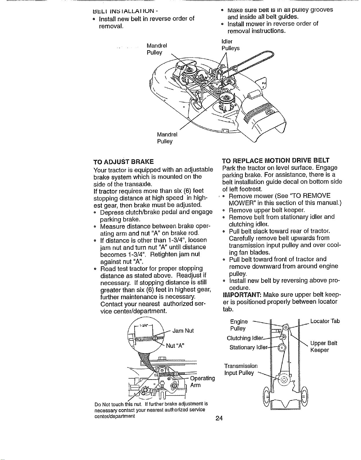
I:I_-.LI IN_5 IALLAI IUN -
o Install new belt in reverse order of
removal
Mandrel
Pulley
o MaKe sure Delt IS rn all pulley grooves
and inside all belt guides.
o Install mower in reverse order of
removal irrstructions.
Idler
Pulleys
Mandrel
Pulley
TO ADJUST BRAKE
Your tractor is equipped with an adjustable
brake system which is mounted on the
side of the transaxle_
If tractor requires more than six (6) feet
stopping distance at high speed in high-
est gear, then brake must be adjusted..
o Depress clutch/brake pedal and engage
parking brake.
Measure distance between brake oper-
ating arm and nut "A" on brake rod..
o If distance is other than 1-3/4", loosen
jam nut and turn nut "A" until distance
becomes 1-3/4'L Retighten jam nut
against nut "A".
o Road test tractor for proper stopping
distance as stated above. Readjust if
necessary. If stopping distartce is still
greater than six (6) feet in highest gear,
further maintenance is necessary°
Contact your nearest authorized ser-
vice center/department.
3erating
Arm
_J
Do Not touch this nut, Iffurther brake adjustment is
necessary contact your nearest authorized service
center/department
TO REPLACE MOTION DRIVE BELT
Park the tractor on level surface= Engage
parking brake. For assistance, there is a
belt installation guide decal on bottom side
of left footresL
, o Remove mower (See "TO REMOVE
MOWER" in this section of this manual,)
o Remove upper belt keeper.
o Remove belt from stationary idler and
clutching idler:
o Pull belt slack toward rear of tractor.
Carefully remove belt upwards from
transmission input pulley and over' cool-
ing fan blades.
o Pull belt toward front of tractor and
remove downward from around engine
pulley_
o Install new belt by reversing above pro-
cedure.
IMPORTANT: Make sure upper belt keep-
er is positioned properly between Iocator
tab.
Engine ---------
Pulley
Clutching Idler-
Stationary Idler-
Transrnission
Input Pulley
Keeper
24
TOADJUSTk'_OTIONCONTROLLEVER
Themotioncontrolleverhasbeenpreset
atthefactoryandadjustmentshouldnot
benecessary_
ifforanyreasonthemotioncontrollever
will not hold its position while at a selected
speed, it may be adjusted at the friction
pack located on the right side of transmis-
sion.
o Park tractor on level surface. Stop trac-
tor by turning ignition key to "OFF" posF
tion, and engage parking brake
o Adjust motion control lever by tightening
adjustment iocknut one half (1/2) turn_
NOTE: If for any reason the effort to move
the motion control lever becomes too
excessive, reverse the above adjustment
procedure by loosening Iocknut !/4 to 1/2
turn,
Road test tractor after adjustment and
repeat procedure if necessary.
TRANSMISSION REMOVAL/REPLACE-
MENT
Should your transmission require removal
for service or' replacement, it should be
purged after reinstallation and before
operating the tractor. See "PURGE
TRANSMISSION" in the Operation section
of this manual
Adjustment
Locknut
TO ADJUST STEERING WHEEL ALIGN-
MENT
If steering wheel crossbars are not hori-
zontal (left to right) when wheels are posi-
tioned straight forward, remove steering
wheel and reassemble per instructions in
the Assembly section of this manual
FRONT WHEEL TOE4N/CAMBER
The front wheel toe-in and camber are not
adjustable on your tractor. If damage has
occurred to affect the front wheel toe-in or
camber, contact your nearest authorized
service center.
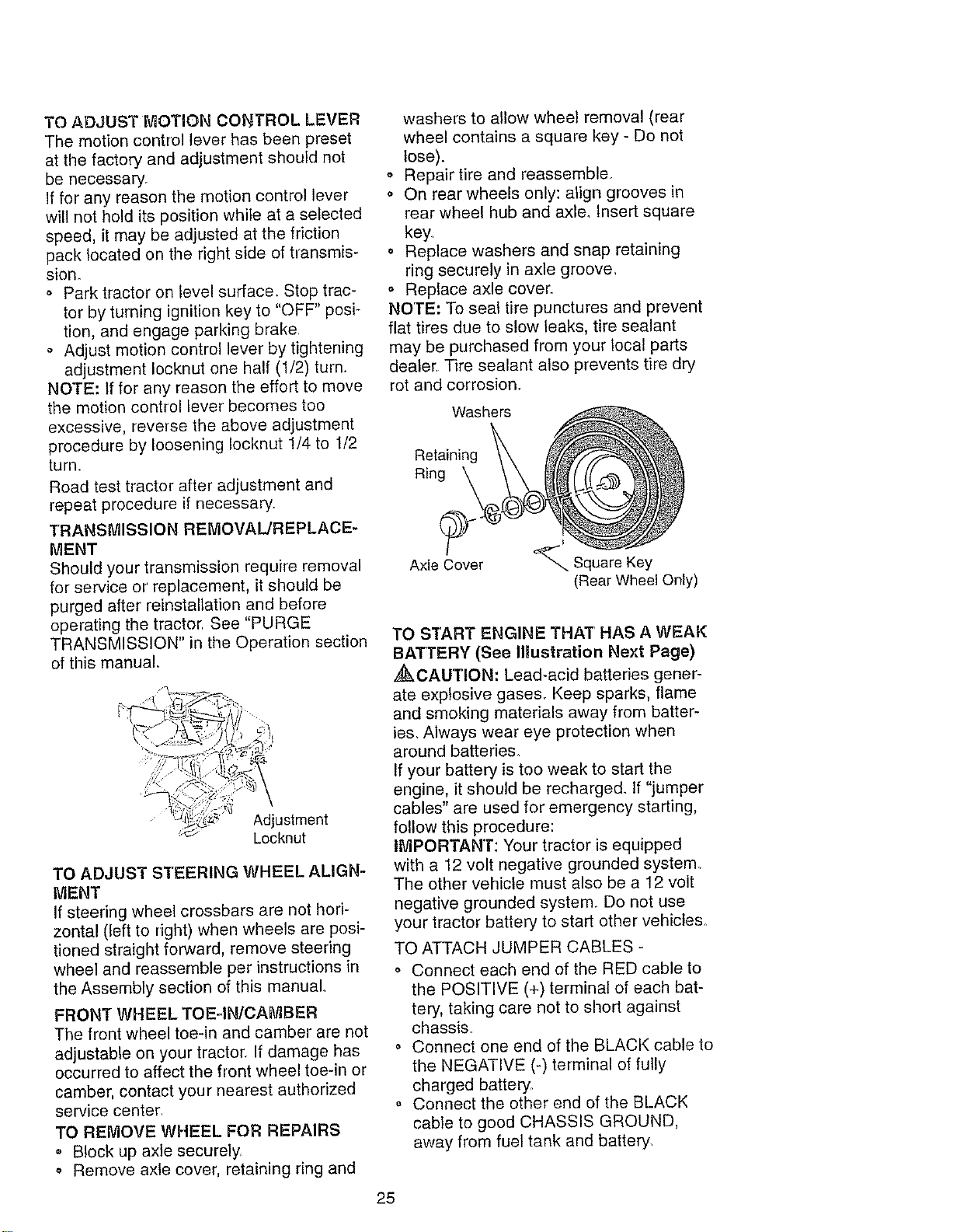
TO REMOVE WHEEL FOR REPAIRS
• Block up axle securely.
Remove axle cover, retaining ring and
washers to allow wheel removal (rear
wheel contains a square key - Do not
lose).
,, Repair tire and reassemble.
o On rear wheels only: align grooves in
rear wheel hub and axle. Insert square
key.
o Replace washers and snap retaining
ring securely in axle groove,
o Replace axle cover.
NOTE: To seal tire punctures and prevent
flat tires due to slow leaks, tire sealant
may be purchased from your local parts
dealer. Tire sealant also prevents tire dry
rot and corrosion.
Washers
Retaining
Ring
Axle Cover
Square Key
(Rear Wheel Only)
TO START ENGINE THAT HAS A WEAK
BATTERY (See IHustration Next Page)
_CAUTION: Lead-acid batteries gener-
ate exp}osive gases. Keep sparks, flame
and smoking materials away from batter-
ies. Always wear eye protection when
around batteries_
If your battery is too weak to start the
engine, it should be recharged. If "jumper
cables" are used for emergency starting,
follow this procedure:
ltVIPORTAN'r: Your tractor is equipped
with a 12 volt negative grounded system.
The other vehicle must also be a 12 voit
negative grounded system Do not use
your tractor battery to start other vehicles.
TO ATTACH JUMPER CABLES -
o Connect each end of the RED cable to
the POSITIVE (+) terminal of each bat-
tery, taking care not to short against
chassis
o Connect one end of the BLACK cable to
the NEGATIVE (-) terminal of fully
charged battery.
o Connect the other end of the BLACK
cable to good CHASSIS GROUND,
away from fuel tank and battery,
25
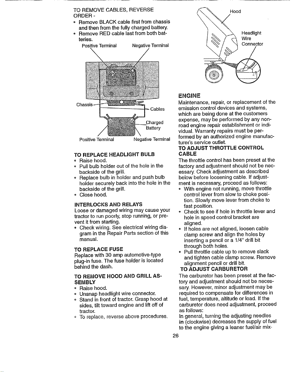
TOREMOVECABLES,REVERSE
ORDER-
° RemoveBLACKcablefirstfrom chassis
and then from the fully charged battery°
Remove RED cable last from both bat-
teries.
Positive Terminal Negative Terminal
Hood
Headlight
Wire
Connector
Positive Terminal
.3harged
Battery
Negative Terminal
TO REPLACE HEADLIGHT BULB
o Raise hood.
o Pull bulb holder out of the hole in the
backside of the grill
o Replace bulb in holder and push bulb
holder securely back into the hole in the
backside of the grill
° Close hood.
INTERLOCKS AND RELAYS
Loose or damaged wiring may cause your
tractor to run poorly, stop running, or pre-
vent it from starting.
o Check widng. See electrical wiring dia=
gram in the Repair Parts section of this
manual.
TO REPLACE FUSE
Replace with 30 amp automotive..type
plug-in fuse° The fuse holder is located
behind the dash.
TO REMOVE HOOD AND GRILL AS-
SEMBLY
o Raise hood.
o Unsnap headlight wire connector.
o Stand in front of tractor. Grasp hood at
sides, tilt toward engine and lift off of
tractor.
o To replace, reverse above procedure&
ENGHNE
Maintenance, repair, or replacement of the
emission control devices and systems,
which are being done at the customers
expense, may be performed by any non-
road engine repair establishment or indi-
vidual. Warranty repairs must be per-
formed by an authorized engine manufac-
turer's service outlet.
TO ADJUST THROTTLE CONTROL
CABLE
The throttle control has been preset at the
factory and adjustment should not be nec-
essary_ Check adjustment as described
below before loosening cable. If adjust-
ment is necessary, proceed as follows:
° With engine not running, move throttle
control lever from slow to choke posi-
tion_ Slowly move lever from choke to
fast position_
o Check to see if hole in throttle lever and
hole in speed control bracket are
aligned_
o If holes are not aligned, loosen cable
clamp screw and align the holes by
inserting a pencil or a 1/4" drill bit
through both holes.
o Pull throttle cable up to remove slack
and tighten cable clamp screw. Remove
alignment pencil or drill bit.
TO ADJUST CARBURETOR
The carburetor has been preset at the fac-
tory and adjustment should not be neces-
sary. However, minor adjustment may be
required to compensate for differences in
fuel, temperature, altitude or load. If the
carburetor does need adjustment, proceed
as follows:
In general, turning the adjusting needles
in (clockwise) decreases the supply of fuel
to the engine giving a leaner fuel/air mix-
26
ture.Turningtheadjustingneedlesout
(counterclockwise)increasesthesupplyof
fueltotheenginegivinga richerfuel/air
mixture.
RMPORTANT:Damageto theneedlesand
theseatsin carburetor may result if nee-
dle is turned in too tight.
NOTE: The carburetor on this engine is
low emission, it is equipped with an idle
fuel adjusting needle with a limiter cap,
which allows some adjustment within the
limits allowed by the cap,, Do not attempt
to remove the limiter cap. The limiter cap
cannot be removed without breaking the
adjusting needle,
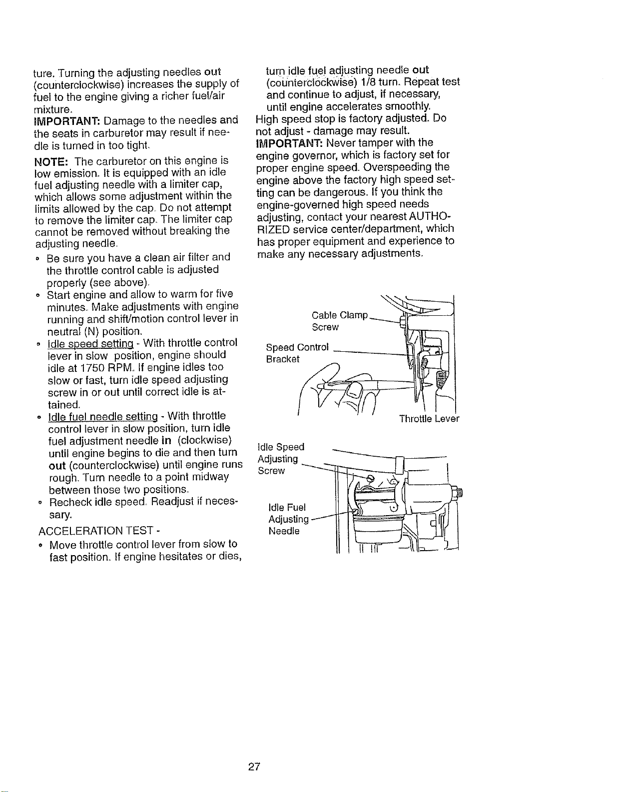
o Be sure you have a clean air filter and
the throttle control cable is adjusted
properly (see above).
o Start engine and allow to warm for five
minutes., Make adjustments with engine
running and shift/motion control lever in
neutral (N) position,
o Idle s_ - With throttle control
lever in slow position, engine should
idle at 1750 RPM. If engine idles too
slow or fast, turn idle speed adjusting
screw in or out until correct idle is at-
tained.
o Idle fuel needle settinq - With throttle
control lever in slow position, turn idle
fuel adjustment needle in (clockwise)
until engine begins to die and then turn
out (counterclockwise) until engine runs
rough. Turn needle to a point midway
between those two positions.,
o Recheck idle speed_ Readjust if neces-
sary_
ACCELERATION TEST -
o Move throttle control lever from slow to
fast position. If engine hesitates or dies,
turn idle fqe! adjusting needle out
(co'dntercl6ckwise) 1/8 turn. Repeat test
and continue to adjust, if necessary,
until engine accelerates smoothly,
High speed stop is factory adjusted. Do
not adjust - damage may result.
IMPORTANT: Never tamper with the
engine governor, which is factory set for
proper engine speed. Overspeeding the
engine above the factory high speed set--
ting can be dangerous. If you think the
engine-governed high speed needs
adjusting, contact your nearest AUTHO-
RIZED service center/department, which
has proper equipment and experience to
make any necessary adjustments.
Cable Clam
Screw
Speed Control
Bracket
Throttle Lever
Idle Speed
Adjusting "_
Screw
Idle Fuel
Adjusting
Needle
I
27
Irnmediatelyprepareyourtractorforstor-
ageattheendoftheseasonor ifthetrac-
torwillnotbeusedfor 30daysormore.
,_kCAUTJON: Never store the tractor with
gasoline in the tank inside a building
where fumes may reach an open flame or
spark. Allow the engine to cool before stor-
ing in any enclosure°
TRACTOR
Remove mower from tractor for winter
storage. This will allow you to clean it thor-
oughly Remove all dirt, grease, leaves,
etc. Store in a clean, dry area.
o Clean entire tractor (See "CLEANING" in
the Maintenance section of this manual).
• Inspect and replace belts, if necessary
(See belt replacement instructions in the
Service and Adjustments section of this
manual).
Lubricate as shown in the Maintenance
section of this manual
o Be sure that all nuts, bolts and screws
are securely fastened. Inspect moving
parts for damage, breakage and wear,
Replace if necessary.
o Touch up all rusted or chipped paint sur-
faces; sand lightly before painting.
BATTERY
° Fully charge the battery for storage_
o After a period of time in storage, battery
may require recharging.
o To help prevent corrosion and power
leakage during long periods of storage,
battery cables should be disconnected
and battery cleaned thoroughly (see "TO
CLEAN BATTERY AND TERMINALS" in
the Maintenance section of this manual).
• After cleaning, leave cables disconnect-
ed and place cables where they cannot
come in contact with battery terminals.
o If battery is removed from tractor for
storage, do not store battery directly on
concrete or damp surfaces.
ENGINE
FUEL SYSTEM
IMPORTANT: It is important to prevent
gum deposits from forming in essential fuel
system parts such as carburetor, fuel filter,
fuel hose, or tank during storage. Also,
experience indicates that alcohol blended
fuels (called gasohol or' using ethanol or
methanol) can attract moisture which leads
to separation and formation of acids during
storage, Acidic gas can damage the fuel
system of an engine while in storage.
o Drain the fuel tank.
o Start the engine and let it run until the
fuel lines and carburetor are empty.
o Never use engine or carburetor cleaner
products in the fuel tank or permanent
damage may occur:
o Use fresh fuel next season°
NOTE: Fuel stabilizer is an acceptable
alternative in minimizing the formation of
fuel gum deposits during storage. Add sta-
bilizer to gasoline in fuel tank or storage
container, Always follow the mix ratio
found on stabilizer container: Run engine
at least 10 minutes after adding stabilizer
to allow the stabilizer to reach the carbure-
tor. Do not drain the gas tank and carbure-
tor if using fuel stabilizer.
ENGINE OIL
, Drain oil (with engine warm) and replace
with clean engine oil. (See "ENGINE" in
the Maintenance section of this rnanual)_
CYLINDERS
o Remove spark plug(s).
o Pour one ounce of oil through spark plug
hole(s) into cylinder(s).
o Turn ignition key to "START" position for
a few seconds to distribute oil,
• Replace with new spark plug(s).
OTHER
o Do not store gasoline from one season
to another.
Replace your gasoline can if it starts to
rust. Rust and/or dirt in your gasoline will
cause problems.
o If possible, store your tractor indoors
and cover it to give protection from dust
and dirL
• Cover your tractor with a suitable protec-
tive cover that does not retain moisture,
Do not use plastic_ Plastic cannot
breathe, which allows condensation to
form and cause your tractor to rusL
IMPORTANT: Never cover tractor while
engine and exhaust areas are still warm.
28
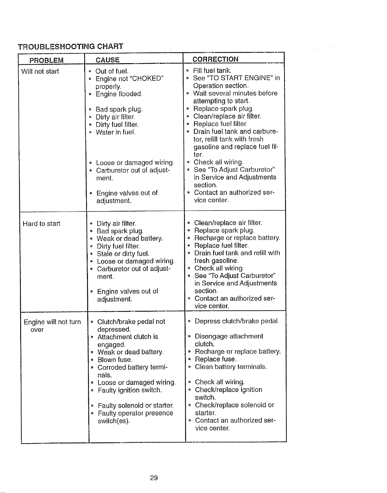
TROUBLESHOOTnNG CHART
PROBLEM
Will net start
Hard to start
Engine will not turn
over
CAUSE
° Out of fuel.
° Engine not"CHOKED"
properly.
• Engine flooded
o Bad spark plug.
° Dirty air filter_
• Dirty fuel filter.
o Water in fuel
,, Loose or damaged wiring
o Carburetor out of adjust-
menL
• Engine valves out of
adjustmenL
o Dirty air filter.
° Bad spark plug.
,, Weak or dead battery.
,, Dirty fuel filter.
o Stale or dirty fuel.
o Loose or damaged wiring
o Carburetor out of adjust-
ment.
o Engine valves out of
adjustmenL
Clutch/brake pedal not
depressed,
Attachment clutch is
engaged_
Weak or dead battery,
Blown fuse,
Corroded battery termi-
nals,
Loose or damaged wiring.
Faulty ignition switch.
Faulty solenoid or starter,
Faulty operator presence
switch(es),
CORRECTION
o Fill fuel tank.
o See "TO START ENGINE" in
Operation section.
o Wait several minutes before
attempting to start.
o Replace spark plug.
o Clean/replace air filter.
o Replace fuel filter
o Drain fuel tank and carbure-
tor, refill tank with fresh
gasoline and replace fuel fil-
teE.
° Check all wiring.
o See "To Adjust Carbureto¢'
in Service and Adjustments
section.
o Contact an authorized ser-
vice center.
o Clean/replace air filter.
Replace spark plug.
Recharge or replace battery.
Replace fuel filter.
Drain fuel tank and refill with
fresh gasoline
Check all wiring
See "To Adjust Carburetor"
in Service and Adjustments
section.
Contact an authorized ser-
vice center.
o Depress clutch/brake pedal
- Disengage attachment
clutch.
o Recharge or replace battery
o Replace fuse,
o Clean battery terminals.
o Check all wiring.
o Check/replace ignition
switch.
o Check/replace solenoid or
starter.
o Contact an authorized ser-
vice center.
29
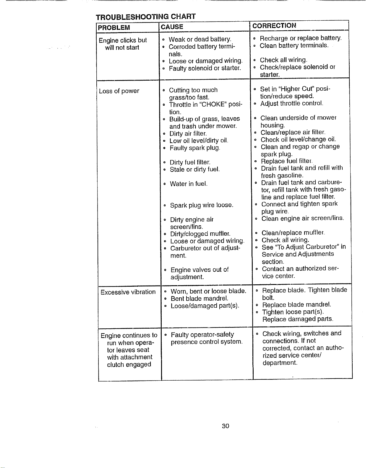
TROUBLESHOOTING CHART
PROBLEM
Engine clicks but
will not start
Excessive vibration
Engine continues to
run when opera-
tor leaves seat
with attachment
clutch engaged
CAUSE CORRECTION
,, Weak or dead battery.
o Corroded battery termi-
nals.
o Loose or damaged wiring.
o Faulty solenoid or starter.
° Cutting too much
grass/too fast.
° Throttle in "CHOKE" posi-
tion.
• Build-up of grass, leaves
and trash under mower_
o Dirty air filter.
o Low oil level/dirty oil.
o Faulty spark plug
o Dirty fuel filter..
Stale or dirty fuel
o Water in fuel
o Spark plug wire loose.
o Dirty engine air
screen/fins.
o Dirty/clogged muffler.
o Loose or damaged wiring
o Carburetor out of adjust-
ment_
o Engine valves out of
adjustment.
o Worn, bent or loose blade_
o Bent blade mandrel..
= Loose/damaged part(s).
o Faulty operator-safety
presence control system,
o Recharge or replace battery.
Clean battery terminals_
Check all wiring
o Check/replace solenoid or
starter.
° Set in "Higher Cut" posi-
tion/reduce speed_
o Adjust throttle control
o Clean underside of mower
housing.
i ° Clean/replace air filter.
= Check oil level/change oil.
= Clean and regap or change
spark plug_
o Replace fuel filter
, = Drain fuel tank and refill with
i fresh gasoline..
o Drain fuel tank and carbure-
tor, refill tank with fresh gaso-
line and replace fuel filter:
o Connect and tighten spark
plug wire.
o Clean engine air screen/fins.
° Clean/replace muffler_
o Check all wiring.
o See "To Adjust Carburetor" in
Service and Adiustments
section
o Contact an authorized ser-
vice center.
......., , ,,,,,
o Replace blade. Tighten blade
bolt.
o Replace blade mandrel
o Tighten loose part(s),
Replace damaged parts_
Check wiring, switches and
connections. If not
corrected, contact an autho-
rized service center/
department.
3O

TROUBLESHOOTING CHART
PROBLEM CAUSE
Poor cut - uneven . Worn, bent or loose blade.
o Mower deck not level.
o Buildup of grass, leaves,
and trash under mower,
o Bent blade mandrel
• Clogged mower deck vent
holes from buildup of
grass, leaves, and trash
around mandrels,,
Mower blades will
not rotate
• Obstruction in clutch
mechanism,
o Worn/damaged mower
drive bell
o Frozen idler pulley
i ° Frozen blade mandrel.
Poor grass dis-
charge
• Engine speed too slow
o Travel speed too fast.
o Wet grass.
o Mower deck not level
o Low/uneven tire air pres-
sure.
o Worn, bent or loose blade
. Buildup of grass, leaves
and trash under mower.
,, Mower drive belt worn
,, Blades improperly
installe&
o improper blades used.
o Clogged mower deck vent
holes from buildup of
grass, leaves, and trash
around mandrels,
Headlight(s) not
worldng (if so
equipped)
Battery will not
charge
o Switch is "OFF"
o Bulb(s) burned out.
o Faulty light switch.
' ° Loose or damaged wiring
o
Blown fuse
° Bad battery cell(s).
o Poor cable connections.
o Faulty regulator (if so
equipped),
o Faulty alternator,
CORRECTION
° Replace blade Tighten blade
bolto
• Level mower deck,.
o Clean underside of mower
housing.
° Replace blade mandrel
o Clean around mandrels to
open vent holes
. Remove obstruction,
o Replace mower drive bell
o Replace idler pulley
° Replace blade mandrel
o Place throttle control in
"FAST" position.,
o Shift to slower speed.
° Allow grass to dry before
mowing.
, Level mower deck.
° Check tires for proper air
pressure.
o Replace/sharpen blade.
Tighten blade bolt.
o Clean underside of mower
housing.
o Replace mower drive belt.
o Reinstall blades sharp edge
down.
o Replace with blade s listed in
this manual
o Clean around mandrels to
open vent holes
o Turn switch "ON".
o Replace bulb(s).
° Checldreplace light switch.
o Check wiring and connections
o Replace fuse.
o Replace battery,
o Check/clean all connections.
o Replace regulator.,
o Replace alternator.
31

TROUBLESHOOTING CHART
PROBLEM CAUSE
I Loss of drive
Engine "backfires"
when turning
engine "OFF"
o Freewheel control in "dis-
, engaged' I position _
• Motion drive belt worn,
damaged or broken,
• Air trapped in transmis-
sion during shipment
or servicing,
• Engine throttle control not
set at "SLOW"
CORRECTION
o Place freewheel control in
"engaged" position_
o Replace motion drive belt.
= Purge transmission,
,, Move throttle control to
"SLOW" position and allow
position for 30 seconds
before stopping engine.
to idle for 30 seconds before
stopping engine,
32


