Loading ...
Loading ...
Loading ...
I IIII I IIIII
I III IIIIIIIII I IIII IIIIIIIIIIIIII III IIIIIIIII II I IIIIIII I II I I I I II IIIIIIIIIIIIIIIIIIIIIIIIIIIIII
ASSEMBLY
i /illlUllllllllUUillllllllliiii i ii i iiiiii i i i li i iii iiiiiiiiiiiiiiii iiii
(If unit is received assembled, repeat all steps in this section to be sure assembly is correct.)
A. PREPARATION
This Operator's Manual has been developed to help
you assemble the unit and to provide its safe opera-
tion. It is important that:you read the entire manua!
to become faznfliar with the unit before you begin as-
sembly.
1. Read your Operator's Manual
2. Tools you will need:
- Phillips Screwdriver
- Adjustable Wrench
B. TUBE AS SEMBLY
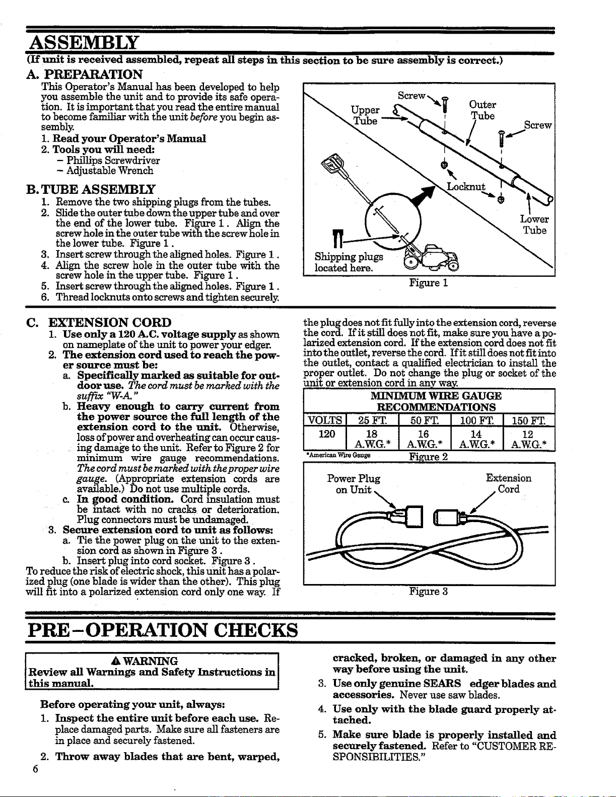
1. Remove the two shipping plugs from the tubes.
2. Slide the outer tube down the upper tube and over
the end of the lower tube. Figure 1. Align the
screw hole in the outer tube with the screw hole in
the lower tube. Figure I.
3. Insert screw through the aligned holes. Figure 1.
4. Align the screw hole in the outer tube with the
screw hole in the upper tube. Figure 1.
5. Insert screw through the aligned holes. Figure 1.
6. Thread locknuts onto screws and tighten securely.
m ii i iJU
Screw T
Upper Outer
Tube r Tube
Shipping plugs
located here.
Figure 1
Screw
C. EXTENSION CORD
1. Use only a 120 A,C. voltage supply as shown
on nameplate of the unit to power your edger.
2. The extension cord used to reach the pow-
er source must be:
a. Specifically marked as suitable for out-
door use. The cord must be marked with the
suffix "TC-A."
b. Heavy enough to carry current from
the power source the full length of the
extension cord to the unit. Otherwise,
loss of power and overheating can occur caus-
ing damage to the unit. Refer to Figure 2 for
minimum wire gauge recommendations.
The cord must be marked with the proper wire
gauge. (Appropriate extension cords are
available.) Do not use multiple cords.
c. In good condition. Cord insulation must
be intact with no cracks or deterioration.
Plug connectors must be undamaged.
3. Secure extension cord to unit as follows:
a. Tie the power plug on the unit to the exten-
sion cord as shown in Figure 3.
b. Insert plug into cord socket. Figure 3.
To reduce the risk of electric shock, this Unit has a polar-
ized plug (one blade is wider than the other). This plug
will fit into a polarized extension cord only one way. If
the plug does not fit fully into the extension cord, reverse
the cord. If it still does not fit, make sure you have a po-
larized extension cord. If the extension cord does not fit
into the outlet, reverse the cord. If it still does not fit into
the outlet, contact a qualified electrician to install the
proper outlet. Do not change the plug or socket of the
_t0r extension cord in any way.
IVHI'_IMUM WIRE GAUGE
RECOMMENDATIONS
VOLTS 25 FT 50 FT. 100 FT. 150 FT........
120 18 16 14 12
A.W.G.* A.W.G.* A.W.G.* A.W.G.*
•_v_ Figure 2
Power Plug Extension
on Unit x Cord
Figure 3
IIII[I I
IIII III I
PRE- OPERATION CHECKS
lit Illlll I I Illll
t _ WARNING !
Review all Warnings and Safety Instructions in
this manual.
Before operating your unit, always:
1. Inspect the entire unit before each use. Re-
place damaged parts. Make sure all fasteners are
in place and securely fastened.
2. Throw away blades that are bent, warped,
6
cracked, broken, or damaged in any other
way before using the unit.
3. Use only genuine SEARS edger blades and
accessories. Never use saw blades.
4. Use only with the blade guard properly at-
tached.
5. Make sure blade is properly installed and
securely fastened. Refer to "CUSTOMER RE-
SPONSIBILITIES."
Loading ...
Loading ...
Loading ...