Loading ...
Loading ...
Loading ...

9
3. Battery Cabinet Installation
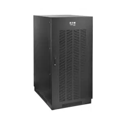
3.6 Battery Cabinet Placement
Place the battery cabinet in a cool location with free airow and away from direct heat sources. The lifespan and performance
of a battery may be dramatically aected by elevated temperature, decreasing 50% for each 8.25° C above 25° C.
1. Prepare the surface where the cabinet will be placed. The surface must be clean, at and able to support the battery
cabinet and other equipment installed nearby. See section 8.Specicationsfor oor loads.
2. Allow adequate clearance around the front and rear of the battery cabinet for ventilation and maintenance. The front
door must be accessible to allow easy access to internal batteries, internal fuses and other overcurrent protection
devices. See section 6.1 Unpacking and Inspection for dimensions and battery cabinet measurements.
3. If the cabinet will be anchored to the oor, install appropriate anchor bolts in the mounting hole located at the
bottom of the cabinet. Use washers to create a level surface between the mounting areas around the anchor bolts.
4. Using extreme caution, remove the bolts securing the battery cabinet to the shipping pallet.
5. Forklift forks should be at maximum width within the cabinet clearance opening and fully inserted to prevent tipping.
Lift cabinet from bottom only. Be careful not to damage the sheet metal oor of the cabinet with the forks.
6. If the battery cabinet will be secured to the oor, carefully align and lower the battery cabinet down on the oor
anchor bolts and secure it in place.
7. If the cabinet will not be secured to the oor, lower it into the designated space and then level it using shims. Leveling
does not aect performance, but does align the battery cabinet with other equipment in the facility.
3.7 Electrical Connection
DANGER! LETHAL HIGH-VOLTAGE HAZARD!
Allwiringshouldbeperformedbyaqualiedelectricianinaccordancewiththewarningsinthis
manual and all applicable electrical and safety codes. Incorrect wiring may cause serious personal
injury and property damage.
• The battery cabinet is connected to the load through a DC circuit breaker. This allows the battery to disconnect from
the load and charger for maintenance and/or repair.
• The DC molded case circuit breakers are CE-approved for branch circuit protection. If replacement is required, CE-
approved components with the same voltage and current rating must be used.
• The size of the load connection cables must consider maximum allowable voltage drop, as well as the cables’
continuous ampere capacity and anticipated ampere discharge rate of the individual battery cabinet. A maximum
voltage drop of 1.5V DC in the load connection cables is recommended. Refer to the UPS unit’s Owner’s Manual for
recommended wire sizes.
• Refer to all applicable local, state and national codes for appropriate cable size and ratings.
• External circuit protection devices (fuses or circuit breakers) must consider the discharge rate of the battery, the wiring
to be protected and the DC short circuit current of the battery.
After performing the installation procedures in section 6. Installation, perform the following:
1. Open the front door of the battery cabinet to access internal components. Use a digital voltmeter when voltage
measurements are required.
2. Determine if the battery has been inadvertently grounded by resetting the circuit breaker to the “On” position and
measuring the voltage between the battery cabinet grounding lug and the positive load connection point within the
cabinet. This voltage should measure 0 (zero) VDC. If the measured voltage is not zero, determine the cause and
correct before proceeding.
3. Return the internal circuit breaker to an open “O” position as a safety precaution while connecting the output cables.
Doing so prevents damage in the event the cables are accidentally shorted.
4. The top of the battery cabinet includes knockouts for load connection cable entry. Punch out the appropriate
knockout and connect the conduit or cable bushing.
5. The output circuit breaker accommodates cables up to 300 mm
2
.
Loading ...
Loading ...
Loading ...