
241-0334
JIG SAW
OPERATOR’S MANUAL
CAUTION:
To Reduce the Risk of Injury, User Must
Read and Understand the Operator’s Manual. Save These
Instructions For Future Reference.
For questions / comments, technical assistance or repair parts –
Please Call Toll Free: 1-866-917-4374 (M-F 8:30am-5:00pm EST).

TABLE OF CONTENTS
Safety Symbols ......................................................... Page 2
Safety Instructions ...................................................... Page 3
Overview/Specications ................................................. Page 8
Assembly ............................................................. Page 9
Operation ............................................................. Page 9
Maintenance .......................................................... Page 17
Troubleshooting ....................................................... Page 18
Warranty .............................................................Page 22

Page 2
SAFETY SYMBOLS
Some of these following symbols may be used on this tool. Please study them and learn their
meaning. Proper interpretation of these symbols will allow you to operate the tool better and
more safely.
Symbol
Name
Designation / Explanation
V Volts Voltage
A Amperes Current
Hz Hertz Frequency (cycles per second)
W Watts Power
lbs Pounds Weight
n
o
No-load speed Rotational speed at no load
SPM Strokes per minute Unit of the tool speed
�
or d.c.
Direct current Type of characteristic of current
Read instruction
manual
To reduce the risk of injury, user must
read instruction manual.
WARNING:
To ensure safety and reliability, all repairs should be performed by a
qualified service technician.

Page 3
SAFETY INSTRUCTIONS
The purpose of safety symbols is to attract your attention to possible dangers. The safety
symbols, and the explanations with them, deserve your careful attention and understand-
ing. The symbol warnings do not, by themselves, eliminate any danger. The instructions and
warnings they give are no substitutes for proper accident prevention measures.
WARNING:
Be sure to read and understand all safety instructions in this manual,
including all safety alert symbols such as “DANGER”, “WARNING” and “CAUTION” before
using this tool. Failure to following all instructions listed below may result in electric
shock, fire, and/or serious personal injury.
SYMBOL MEANING
SAFETY ALERT SYMBOL: Indicates DANGER, WARNING, OR CAUTION. May be used
in conjunction with other symbols or pictographs.
DANGER:
Indicates an imminently hazardous situation, which, if not avoided, will
result in death or serious injury.
WARNING:
Indicates a potentially hazardous situation, which, if not avoided,
could result in death or serious injury.
CAUTION:
Indicates a potentially hazardous situation, which, if not avoided, could
result in minor or moderate injury.
NOTICE: (Without Safety Alert Symbol) Indicates a situation that may result in property
damage.
SAVE THESE INSTRUCTIONS!

Page 4
SAFETY INSTRUCTIONS
GENERAL POWER TOOL
SAFETY WARNINGS
WARNING:
Read all safety
warnings, instructions, illustrations and
specifications provided with this power
tool. Failure to follow all instructions listed
below may result in electric shock, re and/
or serious injury.
SAVE ALL WARNINGS AND INSTRUCTIONS
FOR FUTURE REFERENCE.
The term “power tool” in the warnings refers
to your mains-operated (corded) power tool
or battery-operated (cordless) power tool.
WORK AREA SAFETY
1. Keep work area clean and well lit.
Cluttered or dark areas invite accidents.
2. Do not operate power tools in explosive
atmospheres, such as in the presence of
flammable liquids, gases or dust. Power
tools create sparks which may ignite the
dust or fumes.
3. Keep children and bystanders away
while operating a power tool. Distractions
can cause you to lose control.
ELECTRICAL SAFETY
1. Power tool plugs must match the
outlet. Never modify the plug in any way.
Do not use any adapter plugs with earthed
(grounded) power tools. Unmodied plugs
and matching outlets will reduce risk of
electric shock.
2. Avoid body contact with earthed
or grounded surfaces, such as pipes,
radiators, ranges and refrigerators. There
is an increased risk of electric shock if your
body is earthed or grounded.
3. Do not expose power tools to rain or
wet conditions. Water entering a power tool
will increase the risk of electric shock.
4. Do not abuse the cord. Never use the
cord for carrying, pulling or unplugging the
power tool. Keep cord away from heat, oil,
sharp edges or moving parts. Damaged or
entangled cords increase the risk of electric
shock.
5. When operating a power tool outdoors,
use an extension cord suitable for outdoor
use. Use of a cord suitable for outdoor use
reduces the risk of electric shock.
6. If operating a power tool in a damp
location is unavoidable, use a ground fault
circuit interrupter (GFCI) protected supply.
Use of an GFCI reduces the risk of electric
shock.
PERSONAL SAFETY
1. Stay alert, watch what you are doing
and use common sense when operating a
power tool. Do not use a power tool while
you are tired or under the influence of
drugs, alcohol or medication. A moment of
inattention while operating power tools may
result in serious personal injury.
2. Use personal protective equipment.
Always wear eye protection. Protective
equipment such as a dust mask, non-skid
safety shoes, hard hat or hearing protection
used for appropriate conditions will reduce
personal injuries.
3. Prevent unintentional starting. Ensure
the switch is in the off-position before
connecting to power source and/or battery
pack, picking up or carrying the tool.
Carrying power tools with your nger on the
switch or energizing power tools that have
the switch on invites accidents.
4. Remove any adjusting key or wrench
before turning the power tool on. A wrench
or a key left attached to a rotating part of the
power tool may result in personal injury.
5. Do not overreach. Keep proper footing
and balance at all times. This enables better
control of the power tool in unexpected
situations.

Page 5
SAFETY INSTRUCTIONS
6. Dress properly. Do not wear loose
clothing or jewelry. Keep your hair and
clothing away from moving parts. Loose
clothes, jewelry or long hair can be caught
in moving parts.
7. If devices are provided for the
connection of dust extraction and
collection facilities, ensure these are
connected and properly used. Use of dust
collection can reduce dust-related hazards.
8. Do not let familiarity gained from
frequent use of tools allow you to become
complacent and ignore tool safety
principles. A careless action can cause
severe injury within a fraction of a second.
POWER TOOL USE AND CARE
1. Do not force the power tool. Use the
correct power tool for your application. The
correct power tool will do the job better and
safer at the rate for which it was designed.
2. Do not use the power tool if the switch
does not turn it on and off. Any power tool
that cannot be controlled with the switch is
dangerous and must be repaired.
3. Disconnect the plug from the power
source and/or remove the battery pack,
if detachable, from the power tool before
making any adjustments, changing
accessories, or storing power tools. Such
preventive safety measures reduce the risk
of starting the power tool accidentally.
4. Store idle power tools out of the reach
of children and do not allow persons
unfamiliar with the power tool or these
instructions to operate the power tool.
Power tools are dangerous in the hands of
untrained users.
5. Maintain power tools and accessories.
Check for misalignment or binding of
moving parts, breakage of parts and
any other condition that may affect the
power tool’s operation. If damaged, have
the power tool repaired before use. Many
accidents are caused by poorly maintained
power tools.
6. Keep cutting tools sharp and clean.
Properly maintained cutting tools with sharp
cutting edges are less likely to bind and are
easier to control.
7. Use the power tool, accessories
and tool bits etc. in accordance with
these instructions, taking into account
the working conditions and the work to
be performed. Use of the power tool for
operations different from those intended
could result in a hazardous situation.
8. Keep handles and grasping surfaces
dry, clean and free from oil and grease.
Slippery handles and grasping surfaces do
not allow for safe handling and control of the
tool in unexpected situations.
BATTERY TOOL USE AND CARE
1. Recharge only with the charger
specified by the manufacturer. A charger
that is suitable for one type of battery pack
may create a risk of re when used with
another battery pack.
2. Use power tools only with specifically
designated battery packs. Use of any other
battery packs may create a risk of injury and
re.
3. When battery pack is not in use, keep
it away from other metal objects, like
paper clips, coins, keys, nails, screws or
other small metal objects, that can make
a connection from one terminal to another.
Shorting the battery terminals together may
cause burns or a re.
4. Under abusive conditions, liquid may
be ejected from the battery; avoid contact.
If contact accidentally occurs, flush with
water. If liquid contacts eyes, additionally
seek medical help. Liquid ejected from the
battery may cause irritation or burns.
5. Do not use a battery pack or tool that
is damaged or modified. Damaged or
modied batteries may exhibit unpredictable
behavior resulting in re, explosion or risk of
injury.

Page 6
SAFETY INSTRUCTIONS
6. Do not expose a battery pack or tool
to fire or excessive temperature. Exposure
to re or temperature above 212 °F (100 °C)
may cause explosion.
7. Follow all charging instructions and
do not charge the battery pack or tool
outside the temperature range specified
in the instructions. Charging improperly or
at temperatures outside the specied range
may damage the battery and increase the
risk of re.
SERVICE
1. Have your power tool serviced by a
qualified repair person using only identical
replacement parts. This will ensure that the
safety of the power tool is maintained.
2. Never service damaged battery
packs. Service of battery packs should
only be performed by the manufacturer or
authorized service providers.
SAFETY INSTRUCTIONS FOR
JIG SAW
1. Hold the power tool by insulated
gripping surfaces, when performing an
operation where the cutting accessory may
contact hidden wiring. Cutting accessory
contacting a “live” wire may make exposed
metal parts of the power tool “live” and
could give the operator an electric shock.
2. Use clamps or another practical way
to secure and support the workpiece to a
stable platform. Holding the workpiece by
hand or against your body leaves it unstable
and may lead to loss of control.
IMPORTANT SAFETY
INSTRUCTIONS
1. To reduce the risk of electric shock
or damage to the chargers and batteries,
use only with the MASTERFORCE
®
FLEXPOWER
®
20V battery packs and
chargers listed.
Battery pack Charger
252-8029 (1.5Ah)
252-8031 (2.0Ah)
252-8030 (2.5Ah)
252-8003 (2.5Ah)
252-8034 (4.0Ah)
252-8013 (4.0Ah)
252-8035 (5.0Ah)
252-8005 (5.0Ah)
252-8007 (7.5Ah)
252-8025
252-8037
252-8026
252-8043
2. For best results, your battery and tool
should be stored, charged and used in a
location where the temperature is more
than 41°F (5°C) but less than 104°F (40°C).
Do not store outside or in vehicles.
DANGER:
People with electronic
devices, such as pacemakers, should
consult their physician(s) before using this
product. Operation of electrical equipment
in close proximity to a heart pacemaker
could cause interference or failure of the
pacemaker.
WARNING:
• Some dust created by power sanding,
sawing, grinding, drilling, and other
construction activities contains chemicals
known to the state of California to cause
cancer, birth defects, or other reproductive
harm. Some examples of these chemicals
are:
– Lead from lead-based paints
– Crystalline silica from bricks, cement, and
other masonry products
– Arsenic and chromium from chemically-
treated lumber

Page 7
• Your risk from these exposures varies,
depending upon how often you do this
type of work. To reduce your exposure to
these chemicals:
– Work in a well-ventilated area.
– Work with approved safety equipment,
such as dust masks that are specially
designed to lter out microscopic
particles.
– Avoid prolonged contact with dust from
power sanding, sawing, grinding, drilling,
and other construction activities. Wear
protective clothing and wash exposed
areas with soap and water. Allowing dust
to get into your mouth or eyes or to lie
on the skin may promote absorption of
harmful chemicals.
SAVE THESE INSTRUCTIONS!
SAFETY INSTRUCTIONS

Page 8
OVERVIEW
Lock-off Button
Speed Control
Panel
Bevel Lock Lever
Orbit-Control Lever
Edge Guide
Dust Collection
Port
Hex Key
Metal
Cutting
Blade
Wood Cutting
Blade
Edge-Guide
Locking Screw
Dust-Blower Switch
Guide Roller
Blade
Holder
Blade Release
Lever
LED Work Light
Variable-Speed
Trigger Switch
Base
SPECIFICATIONS
Rated Voltage 20 V d.c.
Speed Range
1: 0-1,500 SPM
2: 0-2,300 SPM
3: 0-3,000 SPM
AUTO: 800 SPM (no-load) /0-3,500
SPM (with AUTO speed activated)
Stroke Length 1 in. (25.4 mm)
Sawing Capacity in Wood 4-11/16 in. (120 mm)
Sawing Capacity in Metal 15/32 in. (12 mm)
Cutting (Bevel) Angle
0-45° both sides, with quick detents
at: 0
°
, ±15
°
, ±30
°
, ±45
°
Weight (without battery) 4 lbs. 13 oz. (2.2 Kg)
Battery Bay

Page 9
OPERATION
WARNING:
If any part is broken or
missing, DO NOT attach the battery pack
or operate the tool until the broken or
missing part is replaced. Failure to do so
could result in possible serious injury.
WARNING:
Do not attempt to
modify this tool or create accessories not
recommended for use with this tool. Any
such alteration or modification is misuse
and could result in a hazardous condition
leading to possible serious injury.
WARNING:
Your tool should
never be connected to the battery pack
when you are assembling parts, making
adjustments, cleaning, or when it is not in
use. Disconnecting the tool will prevent
accidental starting, which could cause
serious personal injury.
ASSEMBLY
PACKING LIST
- Jig saw
- Edge guide
- Edge-guide locking screw
- Dust collection port
- Hex key
- Wood cutting blade (x1)
- Metal cutting blade (x1).
UNPACKING
1. Carefully remove the tool and any
accessories from the carton. Make sure
that all items listed in the packing list are
included.
2. Inspect the tool carefully to make sure
that no breakage or damage occurred
during shipping.
3. Do not discard the packing material
until you have carefully inspected and
satisfactorily operated the tool.
ATTACHING BATTERY PACK
(FIG. 1)
WARNING:
Detach the battery
pack from the tool before making any
assembly, adjustments or changing
accessories. Such preventive safety
measures reduce the risk of starting the
tool accidentally.
FIG. 1
Battery-Release
Button
Battery Bay
1. Align the raised ribs on the battery pack
with the grooves in the battery bay of
the tool, then slide the battery pack onto
the tool.
2. Ensure that the battery-release button
on the battery pack snaps into place
and the battery pack is secured to the
tool before beginning operation.
NOTICE: When placing the battery pack on
the tool, be sure that the raised ribs on the
battery pack align with the grooves on the
tool and the latches snap into place prop-
erly. Improper assembly of the battery pack
can cause damage to internal components.
DETACHING BATTERY PACK
(FIG. 1)
1. Press the battery-release button to
release the battery pack.
2. Pull the battery pack to remove it from
the tool.

Page 10
INSTALLING AND REMOVING
THE SAW BLADE (FIG. 2)
The tool can only accept most commonly
available T-shank blades.
To install the saw blade (FIG. 2a):
1. Disconnect the battery pack.
2. Insert the blade, with its teeth facing
outward as shown in FIG. 2a, into the slot
of the blade holder as far as the blade
can go. The blade will automatically
lock in place.
3. Pull down on the blade to verify that the
blade is securely locked in place.
NOTICE: When inserting the saw blade, the
back of the blade must rest in the groove of
the guide roller.
FIG. 2a
Blade
Holder
Guide
Roller
To remove the saw blade (Fig. 2b):
WARNING:
Always wear
protective gloves when removing the saw
blade from the tool. The saw blade is sharp
and may be hot after prolonged use.
1. Disconnect the battery pack.
2. Turn the blade release lever as shown
and remove the saw blade.
3. Release the blade release lever.
FIG. 2b
Blade
Release
Lever
INSTALLING/REMOVING THE
COVER PLATE (FIG. 3)
Use the cover plate when cutting decora-
tive veneers, plastics, etc. It protects sensi-
tive or delicate surfaces from damage. It is
mounted on the bottom of the tool base.
To install the cover plate:
1. Disconnect the battery pack.
2. Insert the front of the base into the front
of the cover plate and lower the jig saw.
The cover plate should snap securely
and audibly onto the rear of the base
(FIG. 3a).
1
2
FIG. 3a
OPERATION
Page 11
OPERATION
To remove the cover plate:
1. Disconnect the battery pack.
2. Press down on the two release tabs
and slide the cover plate forward. Lift
the cover plate off the base to remove it
(FIG. 3b).
FIG. 3b
Release Tab
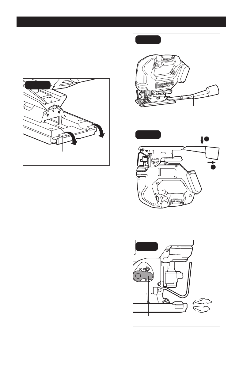
DUST COLLECTION PORT (FIG. 4)
The dust collection port on this jig saw is
compatible with Ø 1-1/4’’ (32 mm) vacuum
hoses or adapters to connect a vacuum
cleaner.
Installation:
1. Disconnect the battery pack.
2. Align the dust collection port as shown
and insert the dust collection port into
the slot in the base, push the dust
collection port forward.
Disassembly:
1. Disconnect the battery pack.
2. Turn the tool upside down on the
workbench, press the port downwards
(a) and then pull it out from the jig saw
(b).
FIG. 4a
Dust Collection
Port
a
b
FIG. 4b
DUST-BLOWER SWITCH (FIG. 5)
FIG. 5
Dust-Blower Switch
Your tool features a dust-blower function to
blow away the dust while cutting for better
visibility.

Page 12
OPERATION
To blow the sawdust, turn the switch to the
position .
To turn off the blowing function, turn the
switch to the
position .
ADJUSTING THE CUTTING
ANGLE (FIG. 6)
a
b
c
FIG. 6
Bevel Lock Lever
Detents
Base
Your tool features detents on the base that
let you quickly set the base to make bevel
cuts at angles of 0°, 15°, 30°, and 45° left
or right.
To adjust the base angle:
1. Disconnect the battery pack.
2. Pull the bevel lock lever as far as it will go
in the direction shown.
3. Move the base slightly forward to
disengage the locking tab from the
detent.
4. Position the base to the desired bevel
angle (0°, ±15°, ±30° or ±45°).
5. Pull the base backward to engage the
locking tab into a detent and retighten
the base-adjustment lever to maintain
the bevel angle. After adjusting the base,
make a sample cut to check the angle.
ORBITAL-ACTION SETTINGS
(FIG. 7)
Your tool is equipped with four orbital-action
settings to best match the cutting speed,
capacity, pattern, and the material being cut.
The orbital action can be adjusted with the
orbit-control lever (Fig. 7). The optimal or-
bital action setting for the respective appli-
cation can be determined through test cuts.
Refer to the following table:
Lever
position
Cutting action Application
0
Straight line cutting
action
For cutting mild steel, stainless steel and plastics.
For clean cuts in wood and plywood.
1 Low orbital action For cutting mild steel, aluminum and hard wood.
2 Medium orbital action
For cutting wood and plywood. For fast cutting in
aluminum and mild steel.
3
Maximum orbital
action
For fast cutting in wood and plywood.

Page 13
NOTE: Always make test cuts in scrap
material rst to determine the best orbital
setting.
In order to reach full orbital action, the blade
must be facing straight forward, the back
of the blade must be resting in the groove
of the guide roller. Orbital action is not
detectable when the saw is running under
no load. The saw must be cutting in order
for orbital action to occur. The effect of
the orbital action is more noticeable when
cutting thicker material.
FIG. 7
Orbit-Control Lever
LOCK-OFF BUTTON (FIG. 8)
FIG. 8
Lock-off Button
Your tool is equipped with a lock-off button,
located above the variable-speed trigger
switch, to help prevent the saw from being
turned on unintentionally.
OPERATION
To lock the saw, depress the lock-off button
from the side marked with icon .
To unlock the saw, depress the lock-off
button from the side marked with icon
.
VARIABLE-SPEED TRIGGER
SWITCH (FIG. 9)
FIG. 9
Variable-Speed Trigger Switch
Your tool is equipped with a variable-speed
trigger switch. The tool can be turned on or
off by depressing or releasing the trigger.
The variable-speed trigger switch delivers
higher speed with increased trigger pressure
and lower speed with decreased trigger
pressure.
1. To start the saw, depress the lock-off
button to the unlock position, and then
squeeze the variable-speed trigger switch.
2. To stop the saw, release the variable-
speed trigger switch and depress the
lock-off button to the locked position.

Page 14
OPERATION
SETTING THE SPEED RANGE
(FIG. 10)
SPEED
AUTO
1
2
3
FIG. 10
SPEED Button
LED Indicator
Your tool is equipped with a speed control
panel, located near the rear end of the
handle. It consists of the “SPEED” button,
3 speed LED indicators and 1 “AUTO” LED
indicator. You can use the “SPEED” button
to select one of the 3 speed ranges and the
AUTO function based on the material to be
cut.
1. Attach the battery pack to the jig saw.
2. Depress the lock-off button to the unlock
position, and briey press the trigger
switch to turn on the LED indicator light.
3. Press the “SPEED” button to choose
one of the three numbered speed
ranges.
4. Press the “SPEED” button once
more after all 3 speed indicators are
illuminated, and then the “AUTO”
indicator will light up which means the
“AUTO” function is activated. When the
tool is turned on, it will automatically
reduce the no-load speed to reduce
the vibration. Once the tool engages
the workpiece, it will reach the highest
speed corresponding to the pressed
distance of the trigger switch. This
makes it easy to position the tool at the
beginning of the cut.
5. The LED indicators will automatically
turn off within 10 seconds after the
trigger switch is released.
NOTE: Your tool is equipped with a memory
function of speed and “AUTO” setting. The
tool will revert to the last used speed range
when turned on again.
The table below shows the relationship
between speed range, speed, and the
number of LED indicators that are lit on the
speed control panel. Refer to this table to
choose appropriate speed depending on
the material to be cut.
LED indicator status
( ON OFF )
Speed
range
Speed/SPM
Recommended
material to be cut
1 0-1,500 Plastics
2 0-2,300
Plastics, wood, mild
steel, stainless steel,
aluminum
3 0-3,000
Plastics, wood, mild
steel, stainless steel,
aluminum
AUTO
800 SPM (no-load)
/0-3,500 SPM
(with AUTO speed
activated)
Wood, mild steel,
aluminum

Page 15
LED WORK LIGHT (FIG. 11)
FIG. 11
Your tool is equipped with an LED work
light, located on the front of the tool. This
provides additional light on the surface of
the workpiece for operation in lower-light
areas.
The LED work light will automatically turn on
with a slight squeeze of the variable-speed
trigger switch before the tool starts running.
It will turn off approximately 10 seconds
after the variable-speed trigger switch is
released.
CUTTING TIPS
WARNING:
Before attaching the
battery pack onto the tool, always check
to determine that the switch performs
properly and returns to the “OFF” position
when released.
WARNING:
Always wear safety
goggles or safety glasses with side
shields during power tool operation or
when blowing dust. If operation is dusty,
also wear a dust mask.
WARNING:
To avoid loss of
control and serious injury, make sure that
the blade reaches the full desired speed
before touching it to the workpiece.
Face the good side of the material down
and secure it in a bench vise, or clamp it
down. Draw cutting lines or designs on the
side of the material facing towards you.
Place the front edge of the saw base on the
workpiece and align the blade with the line
to be cut. Hold the jig saw rmly, turn it on,
and press down to keep the saw base at
against the work as you slowly push the
saw into the workpiece in the direction of
the cut.
Gradually increase the cutting speed,
cutting close to the line (unless you want
to leave stock for nish sanding). You may
have to adjust or relocate the vise or clamps
as you cut to keep the work stable. Do not
force the saw, or the blade teeth may rub
and wear without cutting and the blade may
break. Let the saw do most of the work.
When following curves, cut slowly so that
the blade can cut across the grain. This will
give you an accurate cut and will prevent the
blade from wandering.
USING THE EDGE GUIDE (FIG. 12)
FIG. 12
Edge-Guide
Locking
Screw
Desired Line
of Cut
Hex Key
Edge
Guide
The edge guide allows you to make long
cuts parallel to the edge of the workpiece.
1. Disconnect the battery pack.
2. Insert each edge-guide locking screw
into the screw hole on the front base
of the tool and thread the screws
clockwise 1–2 turns.
OPERATION

Page 16
3. Insert the bar of the edge guide through
the slots in the base of the jig saw. The
edge guide can be inserted from either
side of the base, with the edge guide
facing down.
4. Measure the distance from the edge
of the workpiece to the desired line of
cut. Slide the edge guide to this desired
distance, then fully tighten the locking
screws using the hex key.
CUTTING WITH A STRAIGHT-
EDGE (FIG. 13)
FIG. 13
Always use a rough-cut blade when
possible. Clamp a straightedge onto the
workpiece parallel to the line of cut and ush
with the side of the saw base.
Either (a) rst mark the line of cut and then
position the straightedge parallel and at the
same distance as between the blade and
the side edge of the base or (b) rst mark
the side edge of the base and then clamp
the straightedge on the mark and parallel to
the cut line.
As you cut, keep the saw-base edge ush
against the straightedge and at on the
workpiece.
PLUNGE CUTTING (FIG. 14)
Plunge cutting is useful and time-saving in
making rough openings in softer materials.
It is not necessary to drill a hole for an inside
or pocket cut.
WARNING:
Do not attempt to
perform a bevel plunge cut. Always make
sure the base is set to cut at 0° bevel
1. Draw the outline the opening to be cut.
2. Hold the saw rmly and tilt it forward so
that the front edge of the saw base rests
on the work, but with the blade well
clear of the work.
3. Start the motor, and then very gradually
lower the blade while keeping the front
edge of the base on the workpiece.
When the blade touches the work,
continue pressing down on the front
edge of the saw base and slowly pivot
the saw like a hinge (a) until the blade
cuts through and the base rests at on
the work.
4. Saw ahead on the line of cut line (b).
WARNING:
Do not plunge cut into
metal surfaces.
a
b
FIG. 14
OPERATION

Page 17
MAINTENANCE
METAL CUTTING
WARNING:
Never use the wood-
cutting blade for cutting metals. Failure
to do so could result in serious personal
injury.
1. Clamp the material when cutting metal.
2. Be sure to move the saw along slowly.
3. Use lower speeds.
4. Do not twist, bend, or force the blade.
5. If the saw jumps or bounces, use a
blade with ner teeth.
6. If the blade seems clogged when cutting
soft metal, use a blade with coarser
teeth.
7. For easier cutting, lubricate the blade
with a stick of cutting wax, if available,
or with cutting oil when cutting steel.
8. Thin metal should be sandwiched
between two pieces of wood or tightly
clamped onto a single piece of wood
(wood on top of the metal). Draw the
cut lines or design on the upper piece of
wood.
9. When cutting aluminum extrusion or
angle iron, clamp the work in a bench
vise and saw close to the vise jaws.
10. When sawing tubing and the diameter is
larger than the blade depth, cut through
the wall of the tubing and then insert the
blade into the cut, rotating the tube as
you saw.
OPERATION
BEFORE EACH USE
1. Check for damaged, missing, or worn
parts.
2. Check for loose screws, misalignment
or binding of moving parts, or any other
condition that may affect the operation.
3. If abnormal vibration or noise occurs,
turn the tool off immediately and have
the problem corrected before further
use.
RETIGHTEN THE BASE (FIG. 15)
FIG. 15
Open
Position
Middle
Position
Original
Position
Set Screw
Locking Screw
If the bevel lock lever loosens during use,
retighten it following the procedure below:
1. Disconnect the battery pack.
2. Place the bevel lock lever in the middle
position.
3. Loosen the locking screw
counterclockwise with a PH2
screwdriver (not included).
4. Tighten the set screw nger tight
clockwise with a 4 mm hex key
(included).
5. Tighten the locking screw clockwise
with a PH2 screwdriver.
6. Return the bevel lock lever to its original
position to secure the base in place.
CLEANING
WARNING:
• To avoid serious personal injury, always
remove the battery pack from the
product when cleaning or performing
any maintenance.
• When servicing, use only identical
replacement parts. Use of any other
parts may create a hazard or cause
product damage.

Page 18
MAINTENANCE
TROUBLESHOOTING
The tool may be cleaned most effectively
with compressed dry air. Always wear
safety goggles when cleaning tools with
compressed air. Ventilation openings and
switch selectors must be kept clean and free
of foreign matter. Do not attempt to clean by
inserting pointed objects through openings.
Certain cleaning agents and solvents
damage plastic parts. Some of these are:
gasoline, carbon tetrachloride, chlorinated
cleaning solvents, ammonia and household
detergents that contain ammonia.
STORAGE
Store the tool indoors in a place that is
inaccessible to children. Keep away from
corrosive agents.
PROBLEM POSSIBLE CAUSE SOLUTION
Tool will not start. Or tool
suddenly stops during the
cut.
Battery pack charge is
depleted.
Charge the battery pack.
Battery pack is not
installed properly.
Conrm that the battery
is properly inserted and
secured to the tool.
The tool is overheated. Allow the tool to cool down.
The battery is overheated.
Allow the battery to cool
down.
The tool is overloaded.
Restart the tool and do not
force the tool. Allow the
blade speed to do the job.
The blade binds, jams, or
bums the wood.
The blade is dull. Replace the blade.
An improper blade is
being used.
Choose the right blade for
your operation.
The blade is warped. Replace the blade.
The saw vibrates or shakes.
The blade is damaged. Replace the blade.
The blade is loose.
Remove the blade and
reinstall it.

Page 19
NOTES

Page 20
NOTES

Page 21
NOTES

SAVE YOUR RECEIPTS
THIS WARRANTY IS VOID WITHOUT THEM
JIG SAW
WARRANTY
90-DAY MONEY BACK GUARANTEE:
This MASTERFORCE
®
Jig Saw brand power tool carries our 90-DAY Money Back
Guarantee. If you are not completely satised with your MASTERFORCE
®
brand
power tool for any reason within ninety (90) days from the date of purchase, return
the tool with your original receipt to any MENARDS
®
retail store, and we will provide
you a refund – no questions asked.
3-YEAR LIMITED WARRANTY:
This MASTERFORCE
®
brand power tool carries our famous No Hassle 3-Year Limited
Warranty to the original purchaser. If, during normal use, this MASTERFORCE
®
power
tool breaks or fails due to a defect in material or workmanship within three (3) years
from the date of original purchase, simply bring this tool with the original sales receipt
back to your nearest MENARDS
®
retail store. At its discretion, MASTERFORCE
®
agrees
to have the tool or any defective part(s) repaired or replaced with the same or similar
MASTERFORCE
®
product or part free of charge, within the stated warranty period,
when returned by the original purchaser with original sales receipt. Not withstanding
the foregoing, this limited warranty does not cover any damage that has resulted from
abuse or misuse of the Merchandise. This warranty: (1) excludes expendable parts
including but not limited to blades, brushes, belts, bits, light bulbs, and/or batteries;
(2) shall be void if this tool is used for commercial and/or rental purposes; and (3) does
not cover any losses, injuries to persons/property or costs. This warranty does give you
specic legal rights and you may have other rights, which vary from state to state. Be
careful, tools are dangerous if improperly used or maintained. Seller’s employees are
not qualied to advise you on the use of this Merchandise. Any oral representation(s)
made will not be binding on seller or its employees. The rights under this limited
warranty are to the original purchaser of the Merchandise and may not be transferred
to any subsequent owner. This limited warranty is in lieu of all warranties, expressed
or implied including warranties or merchantability and tness for a particular purpose.
Seller shall not be liable for any special, incidental, or consequential damages. The
sole exclusive remedy against the seller will be for the replacement of any defects
as provided herein, as long as the seller is willing or able to replace this product or is
willing to refund the purchase price as provided above. For insurance purposes, seller
is not allowed to demonstrate any of these power tools for you.
For questions / comments, technical assistance or repair parts –
Please call toll free: 1-866-917-4374 (M-F 8:30am – 5:00pm EST).

10/2022
© 2022 Menard, Inc., Eau Claire, WI 54703