

MultiSync C431
MultiSync C501
MultiSync C551
Please find your model name in the label on the rear side of the monitor.
MODEL: C431, C501, C551
Large Format Display
User’s Manual

Index
DECLARATION OF CONFORMITY ............................................................................................................. English-1
Important Information ................................................................................................................................... English-2
WARNING ....................................................................................................................................... English-2
CAUTION ........................................................................................................................................ English-2
Safety Precautions, Maintenance & Recommended Use............................................................................. English-3
Safety Precautions and Maintenance ............................................................................................. English-3
Recommended Use ........................................................................................................................ English-3
Ergonomics ..................................................................................................................................... English-3
Cleaning the LCD Panel ................................................................................................................. English-4
Cleaning the Cabinet ...................................................................................................................... English-4
Installation .................................................................................................................................................... English-5
Attaching Mounting Accessories ..................................................................................................... English-7
Parts Name and Functions ........................................................................................................................... English-8
Control Panel .................................................................................................................................. English-8
Terminal Panel ................................................................................................................................ English-9
Wireless Remote Control ................................................................................................................ English-10
Operating Range for the Remote Control ....................................................................................... English-11
Setup ............................................................................................................................................................ English-12
Connections ................................................................................................................................................. English-14
Wiring Diagram ............................................................................................................................... English-14
Connecting a Personal Computer ................................................................................................... English-15
Connecting a Player or Computer with HDMI ................................................................................. English-15
Connecting a Computer with DisplayPort ....................................................................................... English-15
Connecting a USB device ............................................................................................................... English-15
Basic Operation ............................................................................................................................................ English-16
Power ON and OFF Modes ............................................................................................................ English-16
Power Indicator ............................................................................................................................... English-17
Using Power Management ............................................................................................................. English-17
Aspect ............................................................................................................................................. English-17
Media Player ................................................................................................................................... English-18
Displayable/playable files ............................................................................................................... English-18
File display screen .......................................................................................................................... English-20
Slideshow display ........................................................................................................................... English-21
Media Player settings ..................................................................................................................... English-21
NETWORK & OTHER SETTINGS.................................................................................................. English-22
Using SHARED SD card SETTINGS .............................................................................................. English-23
Using CONTENTS COPY ............................................................................................................... English-24
Using Emergency contents ............................................................................................................. English-24
Information OSD ............................................................................................................................. English-24
Picture Mode ................................................................................................................................... English-25
OSD (On-Screen-Display) Controls.............................................................................................................. English-26
INPUT ............................................................................................................................................. English-27
PICTURE ........................................................................................................................................ English-27
AUDIO ............................................................................................................................................ English-29
SCHEDULE .................................................................................................................................... English-29
MULTI INPUT .................................................................................................................................. English-30
OSD ................................................................................................................................................ English-31
MULTI DISPLAY ............................................................................................................................. English-32
DISPLAY PROTECTION ................................................................................................................ English-32
CONTROL ...................................................................................................................................... English-33
SYSTEM ......................................................................................................................................... English-35
Remote Control Functions ............................................................................................................................ English-37
Controlling the LCD monitor via RS-232C Remote Control.......................................................................... English-39
Controlling the LCD monitor via LAN Control ................................................................................................English-41
Connecting to a Network ................................................................................................................ English-41
Network Setting by Using an HTTP Browser .................................................................................. English-41
POINT ZOOM ............................................................................................................................................... English-49
Features ....................................................................................................................................................... English-50
Troubleshooting ............................................................................................................................................ English-51
Specifications - C431 ................................................................................................................................... English-53
Specifications - C501 ................................................................................................................................... English-54
Specifications - C551 ................................................................................................................................... English-55
Manufacturer’s Recycling and Energy Information ....................................................................................... English-56
[Notice] About the MPEG-4 AVC, MPEG-4 Visual license included in this product ...................................... English-57
English-1
English
DECLARATION OF CONFORMITY
This device complies with Part 15 of FCC Rules. Operation is subject to the following two conditions. (1) This device may not cause
harmful interference, and (2) this device must accept any interference received, including interference that may cause undesired
operation.
U.S. Responsible Party: NEC Display Solutions of America, Inc.
Address: 500 Park Boulevard, Suite 1100
Itasca, Illinois 60143
Tel. No.: (630) 467-3000
Type of Product: Display Monitor
Equipment Classification: Class B Peripheral
Model: C431
C501
C551
We hereby declare that the equipment specied above
conforms to the technical standards as specied in the FCC Rules.
Cable information
CAUTION: Use the attached specified cables with this color monitor so as not to interfere with radio and television reception.
For mini D-Sub 15-pin, please use a shielded signal cable with ferrite core.
For HDMI, DisplayPort, USB and D-Sub 9-pin, please use a shielded signal cable.
Use of other cables and adapters may cause interference with radio and television reception.
FCC Information
WARNING: The Federal Communications Commission does not allow any modifications or changes to the unit EXCEPT those
specified by NEC Display Solutions of America, Inc. in this manual. Failure to comply with this government regulation could void your
right to operate this equipment.
1. Please use the supplied power cord or equivalent to ensure FCC compliance.
2. This equipment has been tested and found to comply with the limits for a Class B digital device, pursuant to part 15 of the FCC Rules.
These limits are designed to provide reasonable protection against harmful interference in a residential installation. This equipment
generates, uses and can radiate radio frequency energy, and, if not installed and used in accordance with the instructions, may
cause harmful interference to radio communications. However, there is no guarantee that interference will not occur in a particular
installation. If this equipment does cause harmful interference to radio or television reception, which can be determined by turning the
equipment off and on, the user is encouraged to try to correct the interference by one or more of the following measures:
•Reorientorrelocatethereceivingantenna.
•Increasetheseparationbetweentheequipmentandreceiver.
•Connecttheequipmentintoanoutletonacircuitdifferentfromthattowhichthereceiverisconnected.
•Consultthedealeroranexperiencedradio/TVtechnicianforhelp.
Ifnecessary,theusershouldcontactthedealeroranexperiencedradio/televisiontechnicianforadditionalsuggestions.
The user may find the following booklet, prepared by the Federal Communications Commission, helpful: “How to Identify and
Resolve Radio-TV Interference Problems.” This booklet is available from the U.S. Government Printing Office, Washington, D.C.,
20402, Stock No. 004-000-00345-4.
Windows is a registered trademark of Microsoft Corporation.
NEC is a registered trademark of NEC Corporation.
DisplayPort and DisplayPort Compliance Logo are trademarks owned by Video Electronics Standards
Association in the United States and other countries.
All other brands and product names are trademarks or registered trademarks of their respective owners.
The terms HDMI and HDMI High-Definition Multimedia Interface, and the HDMI Logo are trademarks
or registered trademarks of HDMI Licensing Administrator, Inc. in the United States and other countries.
Trademark PJLink is a trademark applied for trademark rights in Japan, the United States of America and
other countries and areas.
microSD and microSD SDHC logos are trademarks of SD-3C, LLC.
CRESTRON and CRESTRON ROOMVIEW are trademarks or registered trademarks of
Crestron Electronics, Inc. in the United States and other countries.
GPL/LGPL Software Licenses
The product includes software licensed under GNU General Public License (GPL), GNU Lesser General Public License (LGPL),
and others.
For more information on each software, see “readme.pdf” inside the “about GPL&LGPL” folder on the supplied CD-ROM.
Adobe and the Adobe logo are either registered trademarks or trademarks of Adobe Systems Incorporated in the United States and/or
other countries.
English-2
Important Information
WARNING
TO PREVENT FIRE OR SHOCK HAZARDS, DO NOT EXPOSE THIS UNIT TO RAIN OR MOISTURE. ALSO, DO NOT
USE THIS UNIT’S POLARIZED PLUG WITH AN EXTENSION CORD RECEPTACLE OR OTHER OUTLETS UNLESS THE
PRONGS CAN BE FULLY INSERTED.
REFRAIN FROM OPENING THE CABINET AS THERE ARE HIGH VOLTAGE COMPONENTS INSIDE. REFER SERVICING
TO QUALIFIED SERVICE PERSONNEL.
CAUTION
TO REDUCE THE RISK OF ELECTRIC SHOCK, MAKE SURE POWER CORD IS UNPLUGGED FROM WALL SOCKET. TO
FULLY DISENGAGE THE POWER TO THE UNIT, PLEASE DISCONNECT THE POWER CORD FROM THE AC OUTLET.
DO NOT REMOVE COVER (OR BACK). NO USER SERVICEABLE PARTS INSIDE. REFER SERVICING TO QUALIFIED
SERVICE PERSONNEL.
This symbol warns user that uninsulated voltage within the unit may have sufficient magnitude to cause electric
shock. Therefore, it is dangerous to make any kind of contact with any part inside this unit.
This symbol alerts the user that important literature concerning the operation and maintenance of this unit has been
included. Therefore, it should be read carefully in order to avoid any problems.
CAUTION: Please use the power cord provided with this display in accordance with the table below. If a power cord is
not supplied with this equipment, please contact NEC. For all other cases, please use the power cord with the plug style that
matches the power socket where the monitor is located. The compatible power cord corresponds to the AC voltage of the power
outlet and has been approved by, and complies with, the safety standards in the country of purchase.
This equipment is designed to be used in the condition of the power cord connected to earth. If the power cord is not connected
to the earth, it may cause electric shock. Please make sure the power cord is earthed properly.
Plug Type North America
European
Continental
U.K. Chinese Japanese
Plug Shape
Region
U.S.A./
Canada
Taiwan
EU U.K. China Japan
Voltage
120*
110
230 230 220 100
* When operating this monitor with its AC 125-240V power supply, use a power supply cord that matches the power supply
voltage of the AC power outlet being used.
NOTE: This product can only be serviced in the country where it was purchased.
Use the power cord which has BSMI mark at both ends when you use this monitor in Taiwan.
•TheintendedprimaryuseofthisproductisasanInformationTechnicalEquipmentinanofceordomesticenvironment.
•Theproductisintendedtobeconnectedtoacomputerandisnotintendedforthedisplayoftelevisionbroadcastsignals.

English-3
English
Safety Precautions and Maintenance
FOR OPTIMUM PERFORMANCE, PLEASE NOTE THE
FOLLOWING WHEN SETTING UP AND USING
THE MULTI-FUNCTION MONITOR:
•DO NOT OPEN THE MONITOR. There are no user
serviceable parts inside and opening or removing covers
mayexposeyoutodangerousshockhazardsorother
risks. Refer all servicing to qualified service personnel.
•Donotbend,crimporotherwisedamagethepowercord.
•Donotplaceanyheavyobjectsonthepowercord.
Damage to the cord may cause shock or fire.
•Thepowersupplycordyouusemusthavebeen
approved by and comply with the safety standards of your
country. (e.g. Type H05VV-F 3G 0.75 mm
2
should be used
in Europe).
•IntheUKuseaBS-approvedpowercordwithamolded
plug having a black (5 A) fuse installed for use with this
monitor.
•Thepowercableconnectoristheprimarymeansof
detaching the system from the power supply. The monitor
should be installed close to a power outlet, which is easily
accessible.
•Donotspillanyliquidsintothecabinetoruseyour
monitor near water.
•Donotinsertobjectsofanykindintothecabinetslots
as they may touch dangerous voltage points, which can
be harmful or fatal, or may cause electric shock, fire or
equipment failure.
•Donotplacethisproductonaslopingorunstablecart,
stand or table, as the monitor may fall, causing serious
damage to the monitor.
•Donotmountthisproductupsidedownforanextended
period of time as it may cause permanent damage to the
screen.
•Donotusethemonitoroutdoors.
•Ifglassisbroken,handlewithcare.
•For reliable performance and long useful life of this
product, it is mandatory to not cover any vents on the
monitor.
•Ifmonitororglassisbroken,donotcomeincontactwith
the liquid crystal and handle with care.
•Allowadequateventilationaroundthemonitor,sothat
heat can properly dissipate.
•Donotblockventilatedopeningsorplacethemonitor
near a radiator or other heat sources.
•Donotputanythingontopofthemonitor.
•Handlewithcarewhentransporting.Savepackagingfor
transporting.
•Itisrecommendedtowipeholescleanaminimumof
once a month.
•To ensure the monitor’s reliability, please clean the holes
at the rear side of the cabinet at least once a year to
remove dirt and dust.
•WhenusingaLANcable,donotconnecttoaperipheral
devicewithwiringthatmighthaveexcessivevoltage.
•Donotusethemonitorinhightemperature,humid,dusty,
or oily areas.
•Donotusemonitorunderrapidtemperatureandhumidity
change condition and avoid cold air from air-conditioning
outlet directly, as it may shorten the lifetime of the monitor
or cause condensation. If condensation of water has
happened, let the monitor stand unplugged until the
condensation has disappeared.
Connecting to a TV*
•Cabledistributionsystemshouldbegrounded(earthed)
in accordance with ANSI/NFPA 70, the National Electrical
Code (NEC), in particular Section 820.93, Grounding of
OuterConductiveShieldofaCoaxialCable.
•Thescreenofthecoaxialcableisintendedtobe
connected to earth in the building installation.
Under the following conditions immediately disconnect your
monitor from the wall outlet and refer servicing to qualified
service personnel:
•Ifthepowersupplycordorplugisdamaged.
•Ifliquidhasbeenspilled,orobjectshavefallenintothe
monitor.
•Ifthemonitorhasbeenexposedtorainorwater.
•Ifthemonitorhasbeendroppedorthecabinethasbeen
damaged.
•Ifyounoticeanystructuraldamagesuchascracksor
unnatural wobbling.
•Ifthemonitordoesnotoperatenormallybyfollowing
operating instructions.
Recommended Use
Ergonomics
Torealizethemaximumergonomicbenets,werecommend
the following:
•Forthemonitor’soptimumperformance,allow20minutes
for warming up. Avoid reproduction of still patterns on
the monitor for long periods of time to avoid image
persistence (after image effects).
•Restyoureyesperiodicallybyfocusingonanobjectat
least 5 feet away. Blink often.
•Positionthemonitorata90°angletowindowsandother
lightsourcestominimizeglareandreections.
•Adjustthemonitor’sbrightness,contrastandsharpness
controls to enhance readability.
•Getregulareyecheckups.
•UsethepresetSizeandPositioncontrolswithstandard
signals.
•UsethepresetColorSetting.
•Usenon-interlacedsignals.
•Donotuseprimarycolorblueonadarkbackground,as
it is difficult to see and may produce eye fatigue due to
insufficient contrast.
•Suitable for entertainment purposes at controlled
luminousenvironments,toavoiddisturbingreections
from the screen.
Safety Precautions, Maintenance & Recommended Use
* The product you purchased may not have this feature.

English-4
Cleaning the LCD Panel
•WhentheLCDpanelisdusty,pleasegentlywipewitha
soft cloth.
•CleantheLCDmonitorsurfacewithalint-free,non-
abrasive cloth. Avoid using any cleaning solution or glass
cleaner!
•PleasedonotrubtheLCDpanelwithhardmaterial.
•PleasedonotapplypressuretotheLCDpanelsurface.
•PleasedonotuseOAcleanerasitwillcause
deterioration or discoloration on the LCD panel surface.
Cleaning the Cabinet
•Unplugthepowersupply
•Gentlywipethecabinetwithasoftcloth
•Tocleanthecabinet,dampentheclothwithaneutral
detergent and water, wipe the cabinet and follow with a
dry cloth.
NOTE:DONOTcleanwithbenzenethinner,alkaline
detergent, alcoholic system detergent, glass
cleaner,wax,polishcleaner,soappowder,or
insecticide. Rubber or vinyl should not be in
contactwiththecabinetforanextendedperiod
oftime.Thesetypesofuidsandmaterialscan
cause the paint to deteriorate, crack or peel.
English-5
English
Forboxcontents,pleaserefertotheprintedcontentssheet
providedinthebox.
This device cannot be used or installed without the Tabletop
Stand or other mounting accessory for support. For proper
installation it is strongly recommended to use a trained,
NEC authorized service person. Failure to follow NEC
standard mounting procedures could result in damage to the
equipment or injury to the user or installer. Product warranty
does not cover damage caused by improper installation.
Failure to follow these recommendations could result in
voiding the warranty.
Mounting
DO NOT mount the monitor yourself. Please ask your
supplier. For proper installation it is strongly recommended to
use a trained, qualified technician. Please inspect the location
where the unit is to be mounted. Mounting on wall or ceiling
is the customer’s responsibility. Not all walls or ceilings are
capable of supporting the weight of the unit. Product warranty
does not cover damage caused by improper installation, re-
modeling, or natural disasters. Failure to comply with these
recommendations could result in voiding the warranty.
DO NOT block ventilated openings with mounting
accessories or other accessories.
For NEC Qualified Personnel:
To ensure safe installation, use two or more brackets to
mount the unit. Mount the unit to at least two points on the
installation location.
Please note the following when mounting
on wall or ceiling
•Whenusingmountingaccessoriesotherthanthosethat
are NEC approved, they must comply with the VESA-
compatible (FDMlv1) mounting method.
•NECrecommendsmountinginterfacesthatcomplywith
UL1678 standard in North America.
•NECstronglyrecommends
usingsizeM6screws
(10-12 mm + thickness
of bracket and washers in
length). If using screws
longer than 10-12 mm,
check the depth of the hole.
(Recommended Fasten
Force:470-635N•cm).Bracket
hole should be under 8.5 mm.
•Priortomounting,inspecttheinstallationlocationto
ensure that it is strong enough to support the weight of
the unit so that the unit will be safe from harm.
•For detailed information, refer to the instructions included
with the mounting equipment.
•Makesurethatthereisnogapbetweenthemonitorand
the bracket.
•Whenusedinavideowallcongurationforalonger
time,slightexpansionofthemonitors may happen due to
temperature changes. Due to this it is recommended that
over one millimeter gap is kept between adjacent monitor
edges.
•Wheninstalling,donotapplypressuretothescreenor
excessiveforcetoanypartofthemonitorbypushing
or leaning on it. This may cause the monitor to become
distorted or damaged.
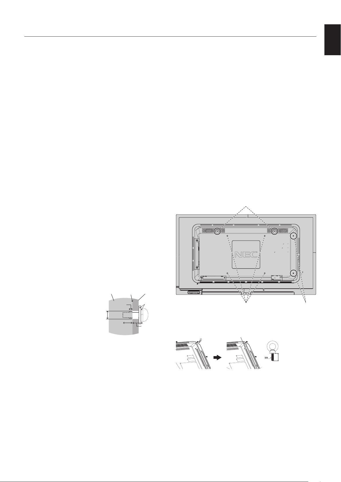
To prevent the LCD monitor from falling off from the wall or
ceiling, NEC strongly recommends using a safety wire.
Please install LCD monitor in a spot of the wall or ceiling
strong enough to support the monitor.
Prepare the LCD monitor using mounting accessories such
as hook, eyebolt or mounting parts and then secure the LCD
monitor with a wire. The safety wire must not be tight.
CAUTION: Do not attempt to hang the monitor using an
installation safety wire. The monitor must be
properly installed on a VESA compatible mount.
Please make sure the mounting accessories are strong
enough to support the LCD monitor before mounting it.
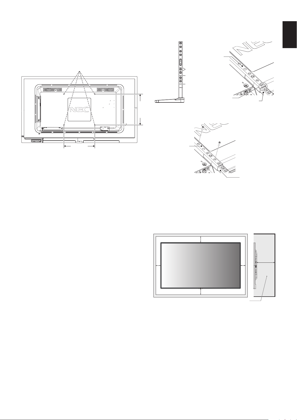
Landscape installation for safety wire
Portrait installation
for safety position
VESA Mounting Interface (M6)
Installing a wire to a monitor
Please use eyebolts to install a wire to the monitor.
Less than 12 mm
Installation
Screw
Unit
10-12 mm
Thickness
of bracket
and washers
under
8.5 mm
No gap
Washers
Mounting
Bracket
No thread
4 mm
English-6
Mounting location
•Theceilingandwallmustbestrongenoughtosupportthe
monitor and mounting accessories.
•DONOTinstallinlocationswhereadoororgatecanhit
the unit.
•DONOTinstallinareaswheretheunitwillbesubjected
to strong vibrations and dust.
•DONOTinstallthemonitornexttoalocationwherethe
main power supply is fed into the building.
•DO NOT install the monitor in a location where people
can easily grab and hang onto the unit or the mounting
equipment.
•Allow for adequate ventilation or provide air conditioning
around the monitor, so that heat can properly dissipate
away from the monitor and from the mounting equipment.
Mounting on ceilings
•Ensurethattheceilingissturdyenoughtosupportthe
weight of the unit and the mounting equipment over time,
againstearthquakes,unexpectedvibrations,andother
externalforces.
•Besuretheunitismountedtoasolidstructurewithin
the ceiling, such as a support beam. Secure the monitor
using bolts, spring lock washers, washer and nut.
•DONOTmounttoareasthathavenosupportinginternal
structure. DO NOT use wood screws or anchor screws for
mounting. DO NOT mount the unit to ceiling or to hanging
xtures.
Maintenance
•Periodicallycheckforloosescrews,gaps,distortions,
or other problems that may occur with the mounting
equipment. If a problem is detected, please refer to
qualified personnel for service.
•Regularlycheckthemountinglocationforsignsof
damage or weakness that may occur over time.
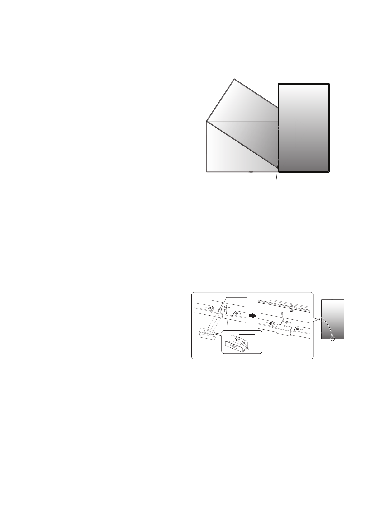
Orientation
•Whenusingthemonitorintheportraitposition,itshould
be rotated clockwise so that the left side is moved to
the top, right side is moved to the bottom. This will allow
forproperventilationandwillextendthelifetimeofthe
monitor. Improper ventilation may shorten the lifetime of
the monitor.
LED Indicator
Changing NEC logo ornament position
When using the monitor in the portrait position, the NEC logo
ornament position can be changed.
Removing the logo ornament: unscrew the installed screw
then take off the logo ornament.
Attaching the logo ornament: adjust the protrusions inside of
the logo ornament into the protrusion hole onthebezel.Make
sure the hole for the screw on the logo ornament and the
hole for the screw on thebezelarealigned. Install the logo
ornament with the screw, which is used for installing the logo
ornament.
(Recommended Fasten Force: 30-40N•cm).
Inside of NEC logo ornament
Screw hole
Protrusions
Screw hole
Protrusion hole
Protrusion hole
CAUTION: Do not use any other screw to install the logo
ornament.
English-7
English
Attaching Mounting Accessories
The monitor is designed for use with the VESA mounting
system.
1. Attach Mounting Accessories
Be careful to avoid tipping the monitor when attaching
accessories.
VESA Mounting Interface (M6)
300 mm
300 mm
Mounting accessories can be attached with the monitor in
the face down position. To avoid damaging the front face,
place the protective sheet on the table underneath the LCD
monitor. The protective sheet was wrapped around the LCD
monitor in the original packaging. Make sure there is nothing
on the table that can damage the monitor.
When using mounting accessories other than NEC compliant
and approved, they must comply with the VESA Flat Display
Mounting Interface Standard (FDMI).
NOTE: Prior to installation, be sure to place the monitor
onaatareawithadequatespace.
2. Installing and removing the optional
table top stand
CAUTION: Installing and removing the stand must be done
by two or more people.
For installation, follow the instructions included with the
stand or mounting equipment. Use only those devices
recommended by the manufacturer.
NOTE: ONLY use screws which are supplied with the
optional table top stand.
When installing, do not put your hands on the
monitor or apply force. The monitor may become
distorted.
When installing the LCD monitor stand, handle the unit with
care to avoid pinching your fingers.
NOTE: Use the ST-401. Please refer to the ST-401
user’s manual for more detail.
Height adjustment
1. The lines on the stand pole are indicators of the height
adjustment. Please adjust the pipe to the lines.
C551 High/Low
C501
C431
Pipe
Adjust the pipe to a line.
Stand pole
2. Please install the stand pole and the pipe with included
screws. Please screw the two screw holes at the pipe.
Pipe
Stand pole
NOTE: Installing the monitor at the wrong height can
cause tipping.
Please install your monitor at proper height.
3. Ventilation Requirements
When mounting in an enclosed space or recessed area,
leave adequate room between the monitor and the enclosure
to allow heat to disperse, as shown below.
100 mm
100 mm
100 mm
100 mm
30 mm
Must be under 40 Degree Celsius.
Allow adequate ventilation or provide air conditioning around
the monitor, so that heat can properly dissipate away from
the unit and the mounting equipment; especially when you
use monitors in a multiple screen configuration.
NOTE: The sound quality of the internal speakers will be
different depending on the acoustics of the room.
English-8
Parts Name and Functions
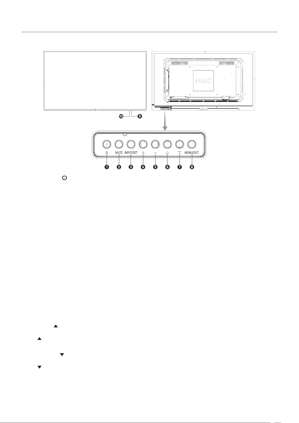
Control Panel
A Power Button ( )
Switches the power on/standby. See also page 16.
B Mute Button (MUTE)
Switches the audio mute on/off.
C Input/Set Button (INPUT/SET)
INPUT: Toggle switches between below inputs.
[DisplayPort], [HDMI1], [HDMI2], [HDMI3],
[VGA (YPbPr/RGB)], [VIDEO], [MP]. These are available
inputs only, shown as their factory preset name.
SET: When OSD (On Screen Display) is shown, this button
acts as a “set button” when you make a selection.
D Plus Button (+)
Increases the audio output level when the OSD menu is
turned off.
Acts as (+) button to increase the adjustment within OSD
menu.
E Minus Button (-)
Decreases the audio output level when the OSD menu is
turned off.
Acts as (-) button to decrease the adjustment within OSD
menu.
F Up Button ( )
Activates the OSD menu when the OSD menu is turned off.
Acts as
button to move the highlighted area up to select
adjustment items within the OSD menu.
G Down Button ( )
Activates the OSD menu when the OSD menu is turned off.
Acts as
button to move the highlighted area down to select
adjustment items within the OSD menu.
H Menu/Exit Button (MENU/EXIT)
Activates the OSD menu when the OSD menu is turned off.
Acts as a back button within the OSD to move to the previous
OSD menu.
Acts as an EXIT button to close the OSD when on the main
menu.
I Remote Control Sensor and Power Indicator
Receives the signal from the remote control (when using the
wireless remote control). See also page 11.
Glows blue when the LCD monitor is in active mode*.
Green and Amber blink alternately when the “SCHEDULE
SETTINGS” function is enabled*
1
.
When a component failure is detected within the monitor, the
indicator will blink red or blink a combination of red and blue.
* If “OFF” is selected in the “POWER INDICATOR”
(see page 35), the LED will not glow when the LCD monitor is in
active mode.
*
1
If “OFF” is selected in the “SCHEDULE INDICATOR”
(see page 35), the LED will not blink.
NOTE: Please refer to the POWER INDICATOR (see page 35).
J Room Light Sensing Sensor
Detects the level of ambient light, allowing the monitor
to make automatic adjustments to the backlight setting,
resultinginamorecomfortableviewingexperience.Donot
cover this sensor. See page 34.
English-9
English
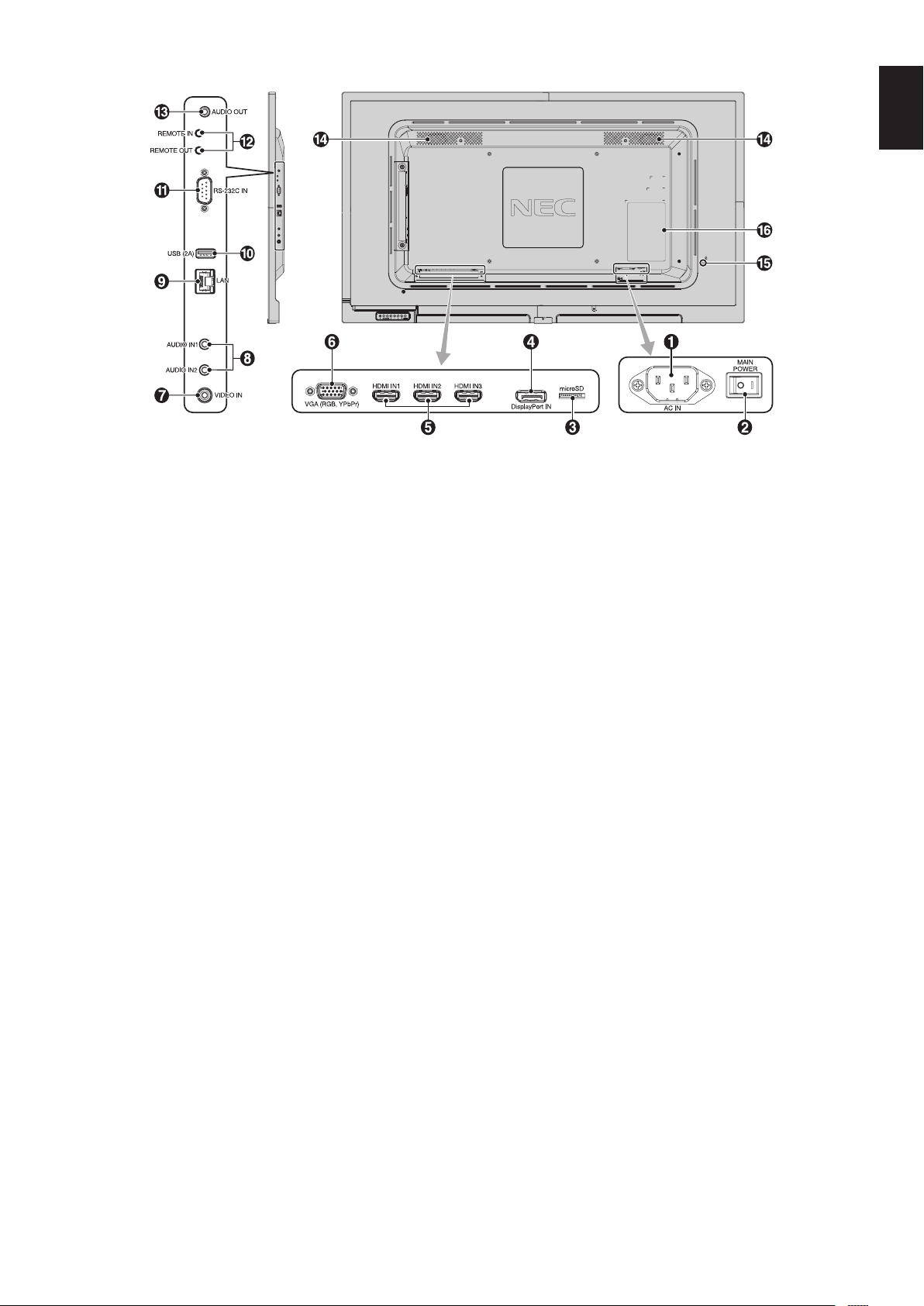
Terminal Panel
USB Upstream
A AC IN Connector
Connects with the supplied power cord.
B Main Power Switch
On/Off switch to turn main power ON/OFF.
C microSD Card Slot
Insert a microSD memory card. To use the Media Player,
please connect a microSD memory card to this port
(See page 19).
To install the microSD card slot cover, pleas e refer to
“Installing microSD card slot cover” (See page 19).
D DisplayPort IN
DisplayPort signals input.
E HDMI IN1/IN2/IN3
Digital HDMI signals input.
F VGA IN (Mini D-Sub 15-pin)
Analog RGB signals input from a personal computer or from
other RGB equipment. This input can be used with an RGB
or YPbPr source. Please select signal type in TERMINAL
SETTINGS. See page 31.
NOTE: When you use this connector for YPbPr, please use a
suitable signal cable. If you have any questions, please ask
your supplier.
G Video IN
Composite video signal input.
H Audio IN1/IN2
Audiosignalinputfromexternalequipmentsuchasa
computer or player.
I LAN port IN (RJ-45)
LAN connection. See page 41.
J USB port
USB (2A): USB storage device port.
To use the Media Player, please connect USB storage device
to this port (See page 15).
K RS-232C IN (D-Sub 9-pin)
ConnectRS-232Cinputfromexternalequipmentsuchasa
computer in order to control RS-232C functions.
L Remote IN/OUT
Use to connect to other displays to create the “daisy-chain”
function. Use the optional sensor unit by connecting it to your
monitor.
NOTE: Do not use this connector for any other purpose.
M Audio OUT
Audio signal output from the AUDIO IN1/IN2, DisplayPort and
HDMItoanexternaldevice(stereoreceiver,amplier,etc.).
NOTE: This connector is not a Headphone terminal.
N Internal Speaker
O Security Slot
Security and theft protection lock compatible with Kensington
security cables/equipment.
For products, visit Kensington’s website.
P Rating Label
English-10
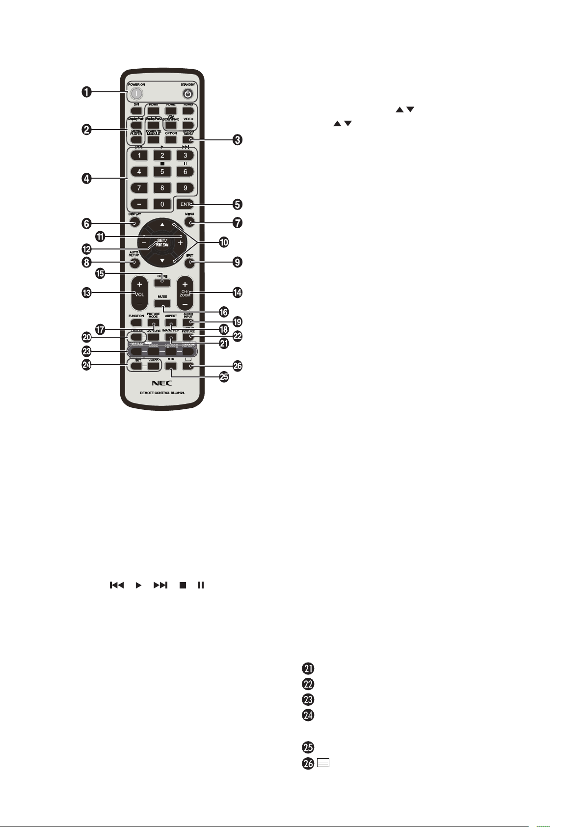
Wireless Remote Control
A POWER ON/STANDBY Button
Switches the power on/standby.
B INPUT Button
Selects the input signal.
Input signal for the Media Player is shown as MP.
C OPTION MENU Button (This button does not work)
D KEYPAD
Press the buttons to set and change passwords, change
channel and set REMOTE ID.
Below buttons are used for CEC (Consumer Electronics
Control) (See page 35) and the Media Player function
(See page 18): 1 , 2 , 3 , 5 , 6 .
E ENT Button (This button does not work)
Confirm the AUTO PLAY FOLDER in MediaPlayer.
F DISPLAY Button
Turns on/off the information OSD. See page 24.
If you lock remote control buttons using the IR LOCK
SETTINGS function, you can unlock the buttons by holding
down this DISPLAY button for more than 5 seconds.
G MENU Button
Turns on/off the menu mode.
H AUTO SET UP Button
Enters auto setup menu. See page 27.
I EXIT Button
Returns to the previous menu within the OSD menu.
J UP/DOWN Button (
/ )
Acts as button to move the highlighted area up or down
to select adjustment items within the OSD menu.
K MINUS/PLUS (-/+) Button
Increases or decreases the adjustment level within the OSD
menu settings.
L SET/POINT ZOOM Button
SET: When OSD is shown, this button acts as “set button”
when you make a selection.
POINT ZOOM: When OSD is not shown, this button acts as
“pointzoombutton”.
M VOLUME UP/DOWN Button (VOL +/-)
Increases or decreases the audio output level.
N CH/ZOOM UP/DOWN Button (CH/ZOOM +/-)
Increases or decreases the POINT ZOOM level.
Please refer to POINT ZOOM (See page 49).
O GUIDE Button (This button does not work)
P MUTE Button
Turns on/off the mute function.
Q PICTURE MODE Button
Selects the picture mode, [HIGHBRIGHT], [STANDARD],
[sRGB], [CINEMA], [CUSTOM1], [CUSTOM2]. See page 25.
HIGHBRIGHT: For moving images such as DVD.
STANDARD: For images.
sRGB:Fortextbasedimages.
CINEMA: For movies.
CUSTOM1 and CUSTOM2: Custom setting.
R ASPECT Button
Selects the picture aspect, [FULL], [WIDE]*, [1:1], [ZOOM]
and [NORMAL]. See page 17.
* HDMI1, HDMI2, HDMI3, VGA (YPbPr) inputs only.
S AUDIO INPUT Button
Selects the audio input source [IN1], [IN2], [DisplayPort],
[HDMI1], [HDMI2], [HDMI3], [MP].
T STILL Button
ON/OFF button: Activates/deactivates still picture mode.
NOTE: This function deactivates when selecting SCREEN
SAVER, POINT ZOOM, TILE MATRIX.
CLOSED CAPTION is not available when STILL is active.
IMAGE FLIP Button (This button does not work)
ACTIVE PICTURE Button (This button does not work)
MULTI PICTURE Button (This button does not work)
REMOTE ID Button
Activates the REMOTE ID function. See page 37.See page 37.
MTS Button (This button does not work)
Button (This button does not work)
NOTE:Thebuttonswithnoexplanationdonotfunction.
English-11
English
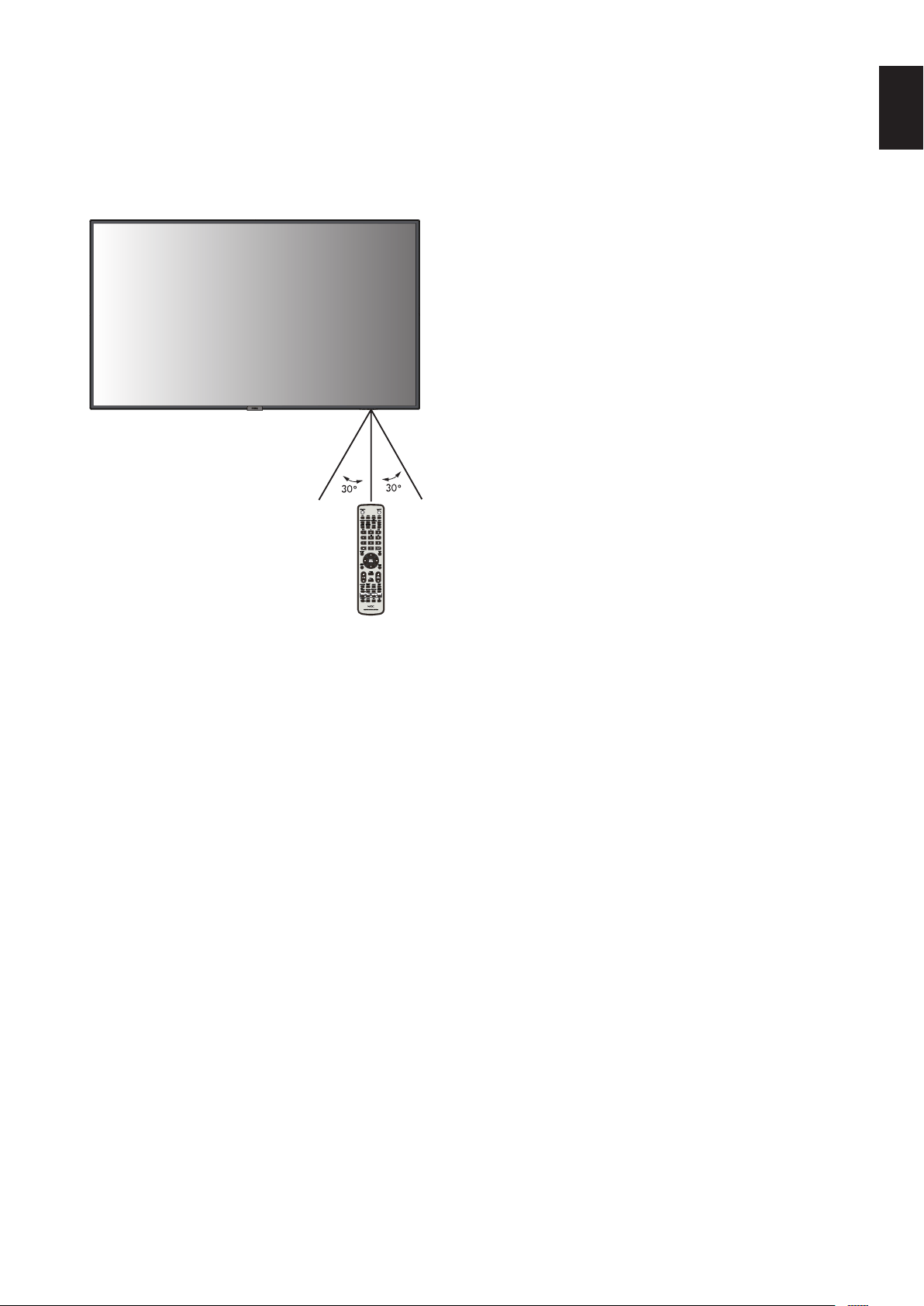
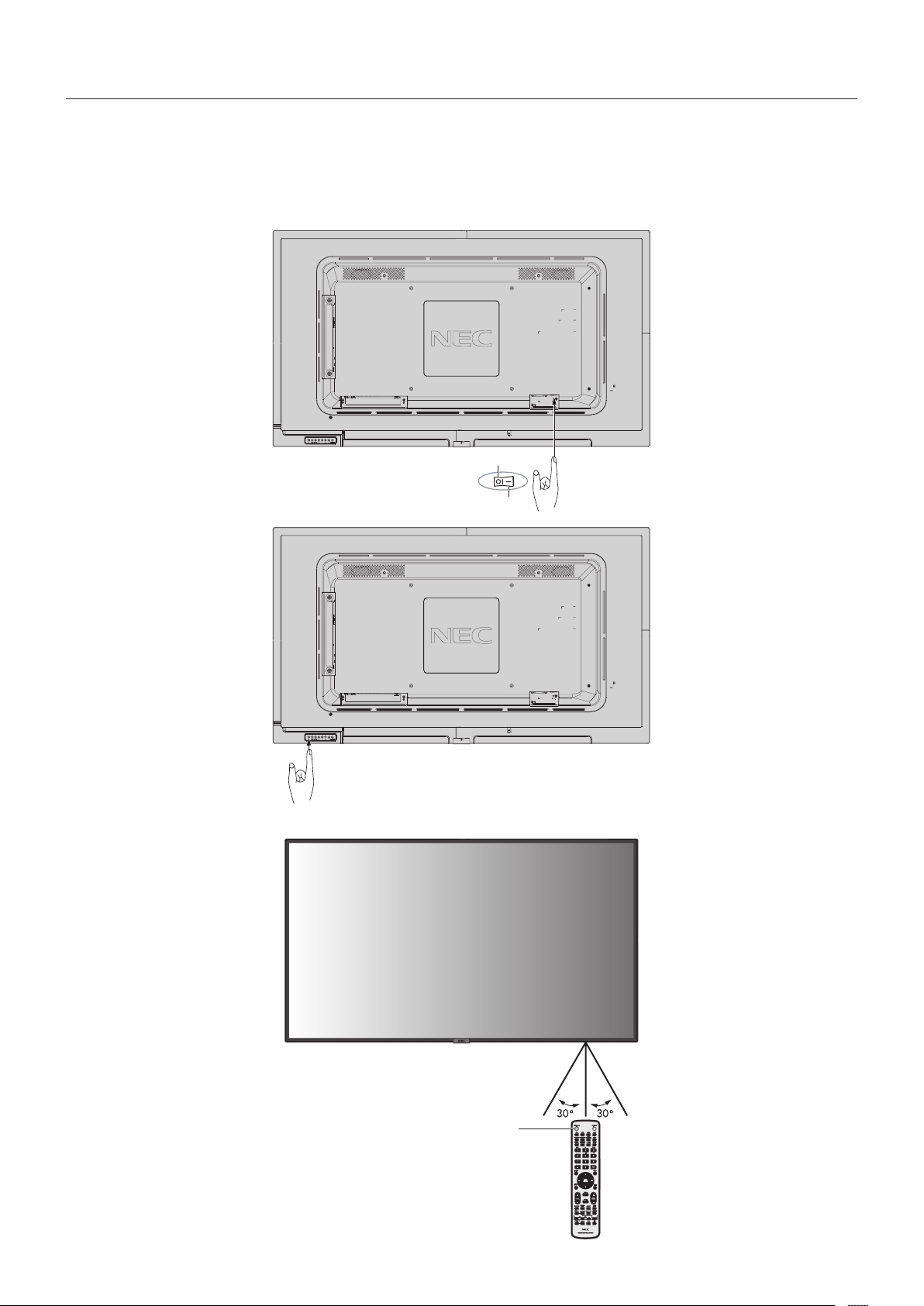
Operating Range for the Remote
Control
Point the top of the remote control toward the LCD monitor’s
remote control sensor during button operation.
Use the remote control within a distance of about 7 m (23 ft.)
fromtheremotecontrolsensor,oratahorizontalandvertical
angleofwithin30°andwithinadistanceofabout3.5m(10ft.).
Caution: Important, the remote control
system may not function when
direct sunlight or strong
illumination strikes the
remote control sensor, or
when there is an object in
the path.
Handling the remote control
•Donotexposetostrongshock.
•Donotallowwaterorotherliquidto
splash on the remote control. If the
remote control gets wet, wipe it dry immediately.
•Avoidexposuretoheatandsteam.
•Excepttoinstallthebatteries,donotopentheremote
control.
English-12
1. Determine the installation location
CAUTION: Installing your LCD monitor must be done by a
qualified technician. Contact your supplier for
more information.
CAUTION: MOVING OR INSTALLING THE LCD MONITOR
MUST BE DONE BY TWO OR MORE PEOPLE.
Failure to follow this caution may result in injury if
the LCD monitor falls.
CAUTION: Do not mount or operate the monitor upside
down.
CAUTION: This LCD monitor has internal temperature
sensors.
If the LCD monitor becomes overheated, a
“Caution” warning will appear. If the “Caution”
warning appears, stop using the unit and allow it
to cool.
If the LCD monitor is used in an enclosed area
or if the LCD panel is covered with a protective
screen, please check the inside temperature of
the monitor by using the “HEAT STATUS” control
in the OSD (see page 32).
IMPORTANT: To avoid scratching the LCD panel, always
place a soft cloth, such as a blanket that is
larger than the monitor’s screen area, on the
table before laying the monitor face down.
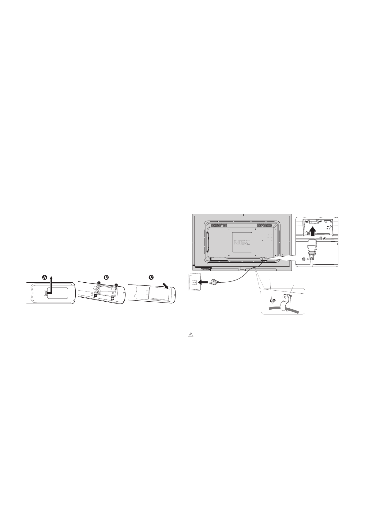
2. Install the remote control batteries
The remote control is powered by two 1.5V AAA batteries.
To install or replace batteries:
A. Press and slide to open the cover.
B. Align the batteries according to the (+) and (–) indications
inside the case.
C. Replace the cover.
CAUTION: Incorrect usage of batteries can result in leaks or
bursting.
NEC recommends the following battery use:
•Place“AAA”sizebatteriesmatchingthe(+)and(-)signs
on each battery to the (+) and (-) signs of the battery
compartment.
•Donotmixbatterybrands.
•Donotcombinenewandoldbatteries.Thiscanshorten
battery life or cause liquid leakage of batteries.
•Removedeadbatteriesimmediatelytopreventbattery
acid from leaking into the battery compartment.
•Donottouchexposedbatteryacid,itmayinjureyourskin.
NOTE: If you do not intend to use the Remote Control for
a long period of time, remove the batteries.
3. Connect external equipment
(See page 14 and page 15)
•Toprotecttheexternalequipment,turnoffthemainpower
before making connections.
•Refertothe user’s manual of your equipment for further
information.
NOTE: Do not connect/disconnect cables when turning
onthemonitororotherexternalequipment,asthis
may result in a loss of the monitor image.
4. Connect the supplied power cord
•Theequipmentshouldbeinstalledclosetoaneasily
accessible power outlet.
•PleasefastenthepowercordtotheLCDmonitorby
attaching the screw and clamp. (Recommended Fasten
Force:139-189N•cm).
•Fullyinserttheprongsintothepoweroutletsocket.
A loose connection may cause image degradation.
NOTE: Please refer to the “Important Information” section
of this user’s manual for proper selection of an AC
power cord.
Screw
Clamp
5. Cable information
CAUTION: Use the attached specified cables with this
color monitor so as not to interfere with radio
and television reception.
For mini D-Sub 15-pin, please use a shielded
signal cable with ferrite core.
For HDMI, DisplayPort, USB and D-Sub
9-pin, please use a shielded signal cable.
Use of other cables and adapters may
cause interference with radio and television
reception.
6. Switch on the power of all the attached
external equipment
When connected with a computer, switch on the power of the
computer first.
7. Operate the attached external equipment
Show the signal on the screen from the desired input source.
Setup

English-13
English
8. Adjust the sound
Make volume adjustments when required.
9. Adjust the screen
(See page 27 and page 28)
Make adjustments to the image position, if necessary.
10. Adjust the image (See page 28)
Make adjustments such as backlight or contrast when
required.
11. Recommended Adjustments
To reduce the risk of the “Image Persistence”, please adjust
the following items based on the application being used:
“SCREEN SAVER”, “SIDE BORDER COLOR” (See page 32),
“DATE & TIME” (See page 30), “SCHEDULE SETTINGS”
(See page 29).
English-14
Connections
NOTE: Do not connect or disconnect cables when turning on the monitor’s main powerorotherexternalequipment’spower,
as this may result in a loss of the monitor image.
NOTE: Use an audio cable without a built-in resistor. Using an audio cable with a built-in resistor turns down the sound.
Before making connections:
* First turn off the power of all the attached equipment and make connections.
* Refer to the user’s manual included with each separate piece of equipment.
* We strongly recommend connecting or disconnecting a USB storage device or a microSD memory card to the monitor when
the monitor’s main power is off.
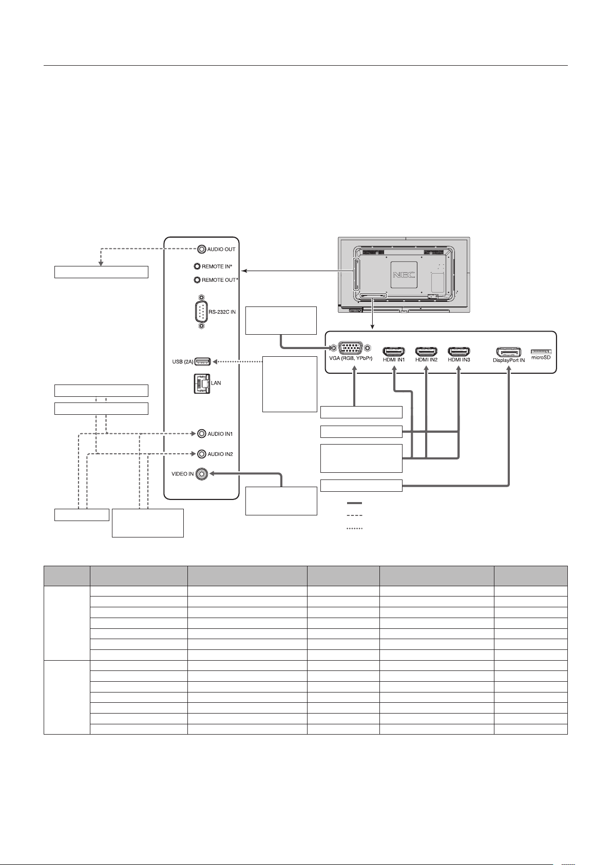
Wiring Diagram
VCR Player or
DVD Player (Video)
Stereo Amplifier
Devices that
require power
supply:
Ex:
MultiPresenter
Stick
Computer
DVD Player
DVD Player (HDMI) or
Computer (HDMI)
Computer (DisplayPort)
Computer (Analog)
DVD Player
(component)
Stereo Amplifier
VCR Player or
DVD Player
AV Amplifier
Solid lines = video signal
Dashed lines = audio signal
Dotted lines = other signal
*: Multiple monitors can have their REMOTE IN/OUT ports daisy chained together. This allows one optional remote sensor kit to be used for multiple monitors.
There is a limit to the number of monitors that can be daisy-chained together (see page 37).
Connected
equipment
Connecting terminal
Setting in
TERMINAL SETTINGS
Input signal name Connecting audio terminal
Input button in
remote control
AV*
2
DisplayPort IN VIDEO LEVEL: RAW/EXPAND*
1
DisplayPort DisplayPort DisplayPort
HDMI IN1 VIDEO LEVEL: RAW/EXPAND*
1
HDMI1 HDMI1 HDMI1
HDMI IN2 VIDEO LEVEL: RAW/EXPAND*
1
HDMI2 HDMI2 HDMI2
HDMI IN3 VIDEO LEVEL: RAW/EXPAND*
1
HDMI3 HDMI3 HDMI3
VGA (RGB, YPbPr) VGA MODE: RGB VGA (RGB) IN1/IN2 VGA (RGB/YPbPr)
VGA (RGB, YPbPr) VGA MODE: YPbPr VGA (YPbPr) IN1/IN2 VGA (RGB/YPbPr)
VIDEO IN — VIDEO IN1/IN2 VIDEO
PC*
3
DisplayPort IN VIDEO LEVEL: RAW/EXPAND*
1
DisplayPort DisplayPort DisplayPort
HDMI IN1 VIDEO LEVEL: RAW/EXPAND*
1
HDMI1 HDMI1 HDMI1
HDMI IN2 VIDEO LEVEL: RAW/EXPAND*
1
HDMI2 HDMI2 HDMI2
HDMI IN3 VIDEO LEVEL: RAW/EXPAND*
1
HDMI3 HDMI3 HDMI3
VGA (RGB, YPbPr) VGA MODE: RGB VGA (RGB) IN1/IN2 VGA (RGB/YPbPr)
VGA (RGB, YPbPr) VGA MODE: YPbPr VGA (YPbPr) IN1/IN2 VGA (RGB/YPbPr)
VIDEO IN — VIDEO IN1/IN2 VIDEO
*1: Please set appropriate setting for input signal.
*2: It is recommended to set YUV in HDMI/DisplayPort MODE (See page 31).
*3: It is recommended to set RGB in HDMI/DisplayPort MODE (See page 31).
English-15
English
Connecting a Personal Computer
Connecting your computer to your LCD monitor will enable you to reproduce your computer’s video signal output.
Some display cards may not be able to support the required resolution for proper image reproduction.
Your LCD monitor shows proper image by adjusting the factory preset timing signal automatically.
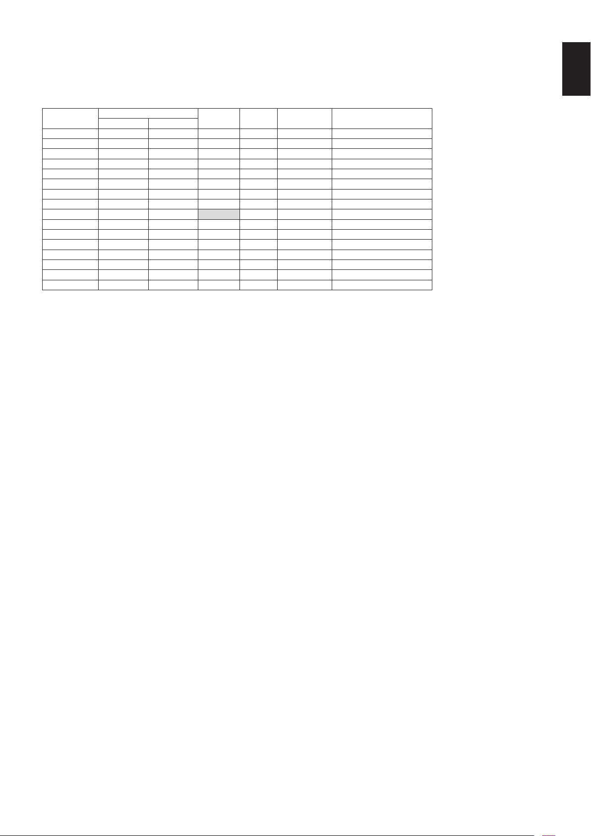
<Typical factory preset signal timing>
Resolution
Scanning frequency
VGA HDMI
DisplayPort
1.1a
Remarks
Horizontal Vertical
640x48031.5kHz60HzYes Yes Yes
800x60037.9kHz60HzYes Yes Yes
1024x76848.4kHz60HzYes Yes Yes
1280x72045.0kHz60HzYes Yes Yes
1280x76847.8kHz60HzYes Yes Yes
1280x80049.7kHz60HzYes Yes Yes
1280x96060.0kHz60HzYes Yes Yes
1280x102464kHz60HzYes Yes Yes
1360x76847.7kHz60HzNo Yes Yes
1366x76847.7kHz60HzYes Yes Yes
1400x105065.3kHz60HzYes Yes Yes
1440x90055.9kHz60HzYes Yes Yes
1600x120075.0kHz60HzYes Yes Yes Compressed image
1680x105065.3kHz60HzYes Yes Yes
1920x108067.5kHz60HzYes Yes Yes Recommended resolution
1920x120074.6kHz60HzYes Yes Yes Compressed image
Connecting a Player or Computer with HDMI
•PleaseuseanHDMIcablewiththeHDMIlogo.
•Itmaytakeamomentforthesignaltoappear.
•Somedisplaycardsordriversmaynotdisplayanimagecorrectly.
•WhenyouuseacomputerwithHDMI,pleasesetOVERSCANto“AUTO”or“OFF”(seepage28).
•Pleasecheckdisplaycardwhenimageiscompressedwith1920x 1080.
•To output HDMI audio, set [HDMI1], [HDMI2] or [HDMI3] at AUDIO INPUT in the OSD or choose [HDMI1], [HDMI2] or
[HDMI3] by the remote control AUDIO INPUT button.
•If the monitor’s main power is turned on after a connected computer is turned on, sometimes images are not displayed.
In this case, please turn off the computer then turn it on again.
Connecting a Computer with DisplayPort
•PleaseuseaDisplayPortcablewiththeDisplayPortcompliancelogo.
•Itmaytakeamomentforthesignaltoappear.
•WhenconnectingaDisplayPortcabletoacomponentwithasignalconversionadapter,animagemaynotappear.
•SelectDisplayPortcablesfeaturealockingfunction.Whenremovingthiscable,holddownthetopbuttontoreleasethelock.
•To output DisplayPort audio, set [DisplayPort] at AUDIO INPUT in the OSD or choose [DisplayPort] by the remote control
AUDIO INPUT button.
•If the monitor’s main power is turned on after a connected computer is turned on, sometimes images are not displayed.
In this case, please turn off the computer then turn it on again.
Connecting a USB device
USB (2A): USB downstream port (Type-A).
To use the Media Player function, please use this port.
•Pleasemakesuretheconnectorshapeandorientationis correctly aligned when connecting the USB device or cable.
•Please refer to the specifications page for power supply information (see page 53, page 54 and page 55).
•When you use the USB (2A) port for power supply, please use a USB cable that supports 2A.
•Do not bind the USB cable. It may cause heat or fire.
English-16
Basic Operation
Power ON and OFF Modes
The LCD monitor power indicator will turn blue while powered on.
NOTE: The Main Power switch must be in the ON position in order to power up the monitor using the remote control or the
Power button.
Main Power Switch
OFF
ON
Power Button
Using the remote control
POWER ON button
English-17
English
Aspect
For VIDEO, VGA (RGB, YPbPr)
FULL
ZOOM NORMAL
For DisplayPort
FULL
1:1 ZOOM NORMAL
For HDMI1, HDMI2, HDMI3
FULL WIDE 1:1 ZOOM NORMAL
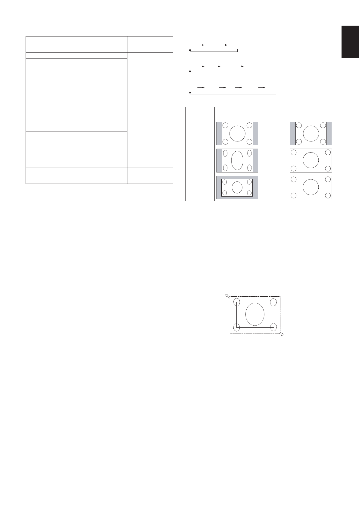
Aspect ratio
of image
Unchanged view*
3
Recommended selection
for picture aspect*
3
4:3
NORMAL
Squeeze
FULL
Letterbox
WIDE
*
3
Grey areas indicate unused portions of the screen.
NORMAL: Reproduces the aspect ratio that is sent from the
source.
FULL: Fills the entire screen.
WIDE:Expandsa16:9letterboxsignaltolltheentire
screen.
1:1: Showstheimageina1by1pixelformat.
ZOOM
Theimagecanbeexpandedbeyondtheactivescreenarea.
The image which is outside of the active screen area is not
shown.
ZOOM
ZOOM
Power Indicator
LED indicator
status and
lighting pattern
Condition Recovery
Glowing blue Normal
1. Turn on the monitor
by the remote
control or the
monitor button.
2. Send an AV signal
input to the monitor.
Blinking green*
1
The monitor has detected no
signal input after a certain
amount of time has passed
when INPUT DETECT is not
NONE, STANDBY USB POWER
is ENABLE, or QUICK TURN
ON is ENABLE.
Glowing amber The monitor has detected no
AV signal input [with network
signal input] after a certain
amount of time has passed
when INPUT DETECT is NONE,
STANDBY USB POWER and
QUICK TURN ON are ENABLE.
Blinking amber The monitor has detected no AV
signal input [no network signal
input] after a certain amount of
time has passed when INPUT
DETECT is NONE, STANDBY
USB POWER and QUICK TURN
ON are ENABLE.
Glowing red Turn off the monitor by the
remote control or the monitor
button.
Turn on the monitor by
the remote control or
the monitor button.
*1: Time setting for AUTO POWER SAVE is available at POWER SAVE
(See page 32).
NOTE: If the indicator is blinking red in a combination
of long and short, a certain failure might have
occurred, please contact your supplier.
Using Power Management
This LCD monitor follows the VESA approved DPM (Display
Power Management) function.
The power management function is an energy saving
function that automatically reduces the power consumption
of the monitor when the keyboard or the mouse has not been
usedforaxedperiod.
This allows your LCD monitor to enter a Power Management
mode if the monitor’s POWER SAVE function is set to
ENABLE, and a certain amount of time has passed since the
monitorrecognized“no signal input”. It will increase the life
and decrease the power consumption of the monitor.
NOTE: Depending on the computer and display card
used, this function may not operate.
After the video signal was lost, the monitor
automatically goes into OFF at a preset time
period.

English-18
Media Player
Plays saved data, such as still and motion images, BGM (Background Music), on a USB storage device or microSD memory
card connected to the monitor.
Top screen of the viewer
• Select [SETTINGS] to change the Media Player settings.
• While “AUTO PLAY” has been set to SLIDESHOW in SETTINGS, the monitor starts performing “AUTO PLAY” by the
operation below:
- When connecting a USB storage device to the USB (2A) port, with the monitor already powered ON and the Media Player
top screen displayed.
- When the input signal is changed to MP, with a USB storage device already connected to the USB (2A) port of the monitor.
For starting “AUTO PLAY”, the system will automatically search the folder which is set in the AUTO PLAY settings FOLDER
field, in the USB storage device and then display found still images or movies. The images and movies will be displayed in the
“Sorted” order.
NOTE: Only 1 USB storage devicecanberecognizedbytheviewer.
A window will appear when you press the control panel buttons while the Media Player is active. You can select to control either
the OSD menu or the Media Player from the window that opens.
Media Player contents are not played while TILE MATRIX is active.
If a monitor is used in portrait position, please set OSD ROTATION to PORTRAIT. Image orientation is changed according to
what you set at OSD ROTATION.
If you play a motion image with the monitor position as portrait, please use the motion image which is rotated anticlockwise
by 90°.
Displayable/playable files
Still
Supported formats
File extension Supported
.jpg, .jpeg, .jpe Baseline, Progressive, RGB, CMYK
.png
Interlace, α channel
Motion image
Supported formats
File extension Video codec Audio codec
.mpg, .mpeg MPEG1, MPEG2 MPEG Audio Layer3 (Abbreviation: MP3)
AAC-LC (Abbreviation: AAC), LPCM
.wmv H.264, WMV MP3, WMA Standard, WMA 9/10 Professional
.mp4 H.264 MP3, AAC
.mov H.264 MP3, AAC
.v,.f4vH.264 MP3, AAC
English-19
English
BGM
Supported formats
File extension Audio codec
.wav LPCM
.mp3 MP3
Information
Item Conditions
Resolution JPEG 5000x5000
PNG 4000x4000
MPEG1 480@30fps
MPEG2 MP@ML, MP@HL, 1080p@30fps / 1080i@60fps
H.264 High profile Lv.4.2, 1080p@30fps / 1080i@60fps
WMV Advanced@L3, Simple&Main
Video bit date - Up to 15Mbps
Audio sampling rate - Upto48KHz
Audio bit rate MP2 Up to 384Kbps
MP3 Up to 320Kbps
AAC Up to 1440Kbps
NOTE: Depending on the file, it may not play even when it satisfies all above mentioned conditions.
Depending on network environments, the type of USB storage device, and file bitrate, it may not play still image files.
You cannot play DRM (Digital Right Management) files.
Themaximumresolutionforamotionimageis1920(Horizontal)x1080(Vertical).
Compatible microSD memory card
Format a microSD memory card in the FAT32 format or FAT16 format.
Refer to the computer’s instruction user’s manual or Help file on how to format a microSD memory card.
Information
Up to 32GB microSDHC is supported.
NOTE: It is not guaranteed to work with all microSD memory card sold commercially.
microSD with CPRM is not supported.
microSD UHS-1 or UHS-2 are not supported.
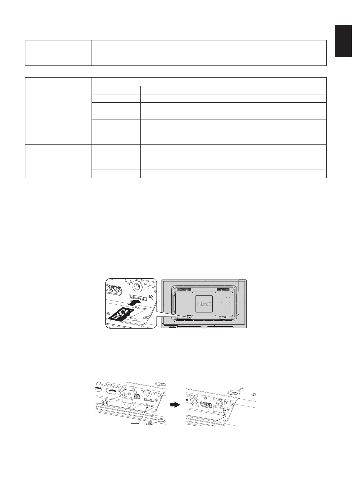
• When inserting a microSD memory card, please make sure of the microSD memory card direction then insert it correctly.
• When ejecting a microSD memory card from the microSD card slot, press the center of the microSD memory card then take
it out.
Installing microSD card slot cover
To secure your microSD memory card, we recommend you install the microSD card slot cover.
Please insert the edge of the microSD card cover to the hole. (Recommended Fasten Force: 139 - 189N•cm).
microSD card cover is set.
Hole
English-20
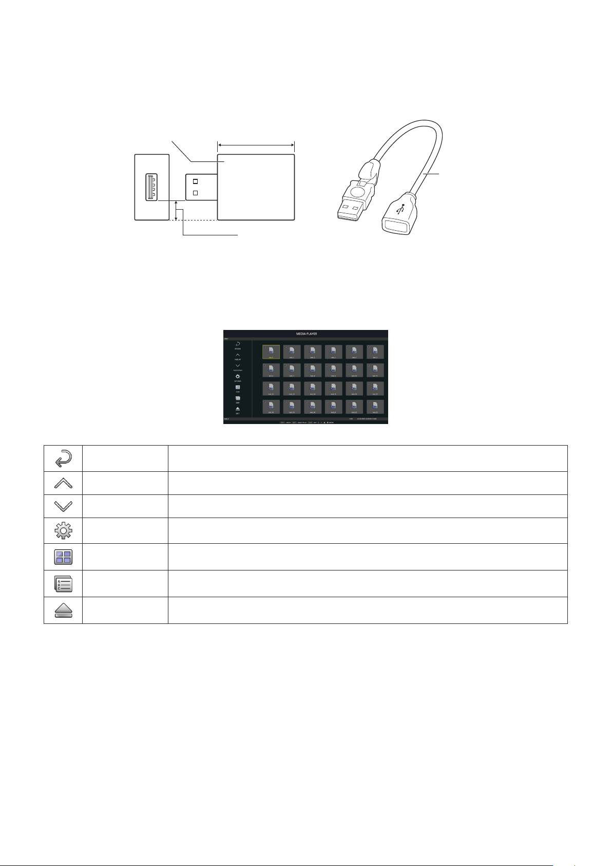
Compatible USB memory
Format a USB memory in the FAT32 format or FAT16 format for using it in the Media Player. Refer to the computer’s instruction
user’s manual or Help file on how to format a USB memory.
Please use a USB memory with this monitor in accordance with the drawing below.
IfthephysicalsizeoftheUSBdeviceislargerthanthanthesupportedsizeslistedbelow,pleaseuseaUSBextensioncable.
C431: under 70 mm
C501: under 145 mm
C551: under 200 mm
USB memory
Extensioncable
Under 5.5 mm
NOTE: Check the format if this device cannot recognizetheconnectedUSBmemory.
It is not guaranteed to work with all USB memories sold commercially.
Please connect the USB memory to the USB (2A) port (See page 14).
File display screen
The files can be displayed using either icons or thumbnails in the Media Player.
Icon display
RETURN Goes back one subsequent level higher.
PAGE UP Displays a list of the previous files.
PAGE DOWN Displaysalistofthenextles.
SETTINGS Displays the setting screen.
THUMBNAILS/ICON Switches between thumbnail display and icon display.
SORT Changestheordertodisplaylesbyname(lename),type(leextension),date(date ofcreation),orsize
(file capacity). The default sorting order is by “Name”.
EJECT Disconnects from the USB storage device or the microSD memory card inserted to the monitor. Please
select EJECT when file list is displayed.
NOTE: Themaximumnumberoflesthat can be displayed in a folder including folder icons is 300.
A folder hierarchy is shown up to level 16.
The icon of a file whose type cannot be determined is indicated by a “?”.
Depending on the file, thumbnail cannot be displayed.
English-21
English
Slideshow display
• Select a folder that contains images or movies.
• A slideshow can be displayed using “MANUAL” in which the images are switched by operating a button on the remote
control, or “AUTO” in which the images are switched automatically at a set interval (PLAY MODE is “AUTO”).
• The default factory setting is “MANUAL”. To perform “AUTO”, set the “PLAY MODE” to “AUTO”.
• The images will be displayed in the order selected under “Sort” on the file display screen.
• When still images in high resolutions are displayed as the Slideshow, it may go back to the file display screen.
Media Player settings
Select the
icon in the file list screen or top screen of the Media Player to display the configuration screen of the Media Player.
The following settings can be configured on the configuration screen.
SLIDESHOW
Menu Function
SCREEN SIZE Selects ACTUAL SIZE or BEST FIT.
PLAY MODE Selects AUTO or MANUAL.
INTERVAL Sets interval time.
REPEAT Checkthecheckboxtorepeatslideshow.
AUDIO FILE Selects an audio file.
BGM CheckthecheckboxtoenableBGM.
PLAY END SCREEN Selects a setting for when the slideshow finishes.
BLACK SCREEN: When the slideshow finishes, a black screen is displayed.
FILE LIST: When the slideshow finishes, it goes back to the file list screen.
SAVE LAST SCREEN: When the slideshow finishes, the last slideshow image is kept on the screen.
AUTO PLAY
Automatically displays selected folder when the input signal is changed to MP, while “AUTO PLAY” has been set to
SLIDESHOW.
Menu Function
AUTO PLAY OFF: Automatic play mode is off.
SLIDESHOW: Automatically plays a selected file.
FOLDER Select a file by SET/POINT ZOOM button and confirm by ENT button.
PRESET CONTENTS
Plays selected folder when the monitor has no signal input.
Menu Function
ENABLE Checkthecheckboxtoenablepresetcontents.
FOLDER Select a file by SET/POINT ZOOM button and confirm by ENT button.
Please press OK to activate above settings.
If OK is not pressed, settings that you set are not activated.
English-22
NETWORK & OTHER SETTINGS
Below are the options for the Network settings and Shared Folder settings for the Media Player.
To select the settings, press the remote control SET/POINT ZOOM button on the NETWORK & OTHER SETTINGS.
NETWORK SETTINGS for Media Player
Menu Function
IP SETTING Set these settings.
IP ADDRESS
SUBNET MASK
DEFAULT GATEWAY
DNS
DNS PRIMARY
DNS SECONDARY
NETWORK INFORMATION for the Media Player displays what you set in the NETWORK SETTINGS for the Media Player.
SHARED FOLDER
There are two settings for configuring the SHARED FOLDER.
Press the remote control SET/ZOOM button to open the shared settings options.
• SHARED SD CARD SETTINGS
Folders saved in a computer on the network can be copied to the connected microSD memory card using a web browser on
the connected computer.
Menu Function
ENABLE CheckthecheckboxtoenableSHAREDSDCARDSETTINGS.
USER NAME USER NAME is displayed. It is the same name as the monitor name and it is not changeable.
PASSWORD Set password.
Please press OK to activate settings in the SHARED SD CARD SETTINGS.
If OK is not pressed, settings that you set are not activated.
• SHARED FOLDER SETTINGS.
Folders saved in a computer on the network can be copied to the connected microSD memory card by controlling the
monitor.
Menu Function
ENABLE CheckthecheckboxtoenableSHAREDFOLDERSETTINGS.
SHARED FOLDER Set the IP address of the network shared folder location that contains the files for copying to the microSD card.
USER NAME Set USER NAME which is used when connecting the monitor to the shared folder.
PASSWORD Set password.
Please press OK to activate settings in the SHARED FOLDER SETTINGS.
If OK is not pressed, settings that you set are not activated.
1 to 4 shared folders can be set.
Whentheconnectiontothesharedfolderfails,anerrormessageisdisplayedandan“x”isdisplayedinthefoldericon.
Carry out the following checks in this case.
- Is the name of the destination folder correct?
- Is the destination folder set for sharing?
- Have access rights been set in the destination folder?
- Are there any displayable files saved in the destination folder?
SHIFT NO SIGNAL
This setting is for a situation when the monitor detects no signal input. If ENABLE is ticked, the monitor goes to no signal status.
The monitor detects no signal when the monitor is in the following conditions:
- After contents or images are played.
- While the monitor is displaying USB
window or SD CARD window.
Menu Function
ENABLE CheckthecheckboxtoenableSHIFTNOSIGNAL.
INTERVAL Set the time when the monitor goes into no signal after playing detected items.
Please press OK to activate settings in the SHIFT NO SIGNAL.
If OK is not pressed, settings that you set are not activated.
English-23
English
Using SHARED SD card SETTINGS
You can copy data to the microSD memory card, such as motion or still images, from a computer connected to the same
network as the monitor.
Please set the NETWORK SETTINGS for the Media Player (See page 22) first to copy data.
NOTE: When the monitor is copying a folder, the LED indicator blinks in red.
When the monitor is in this condition, do not eject a microSD memory card from the monitor and do not turn off the
monitor’s main power. Ejecting the microSD card or turning off the monitor while copying files may corrupt the data.
If you press the STANDBY button on the remote control or the POWER button on the monitor while the LED indicator
is blinking in red, the monitor goes into standby after completing the folder copy.
Files which you can copy are still, motion image and BGM only.
Setting procedure
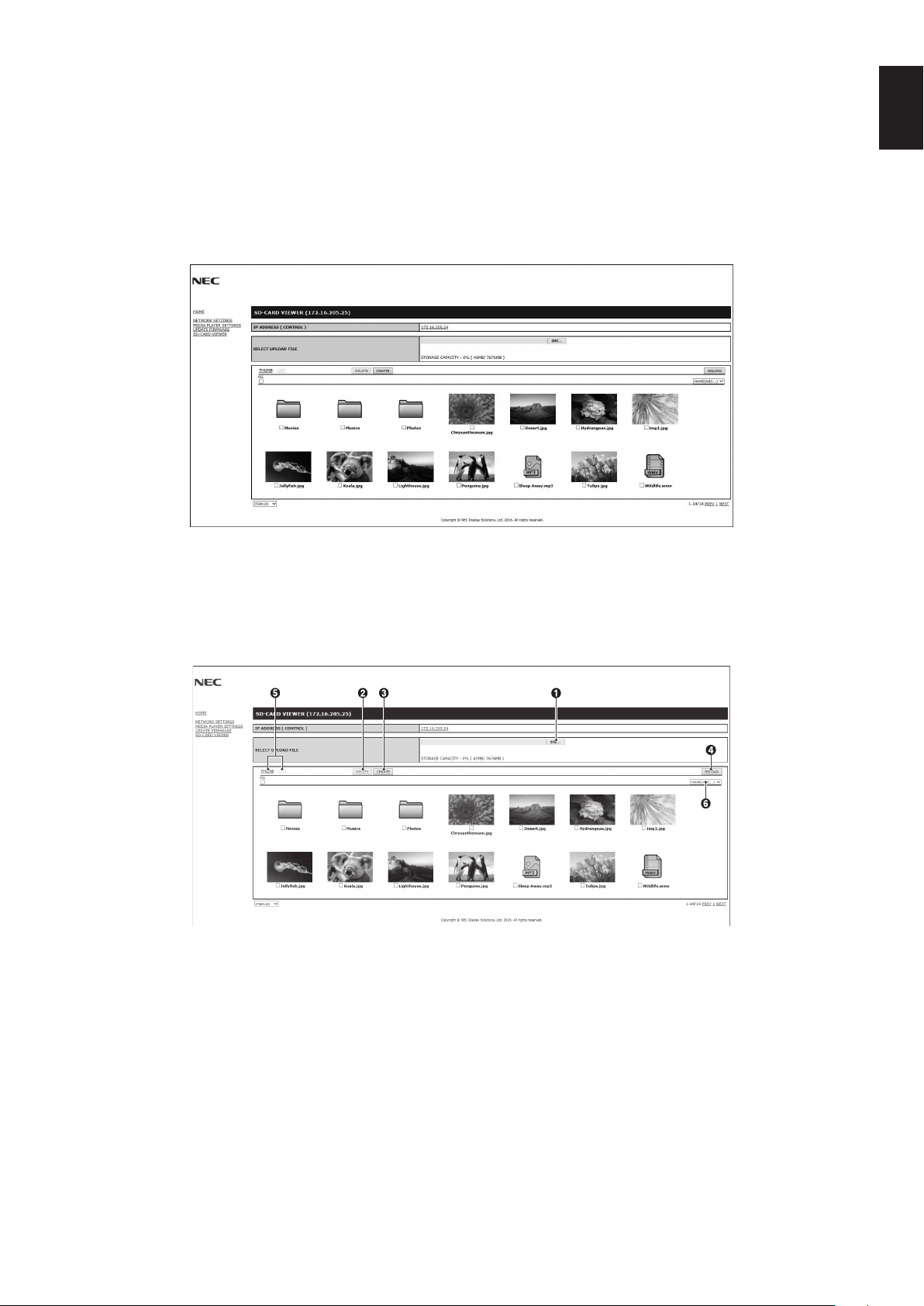
1. Open the Monitor LAN control of the network connected monitor then select SD-CARD VIEWER.
2. Select SEARCH to display the IP ADDRESS of the currently connected monitor and all compatible monitors on the same
network.
3. Select the IP ADDRESS of the currently connected monitor.
4. Enable upload, delete and sort files that are saved in the microSD memory card connected to the monitor.
Function
1. SELECT UPLOAD.
Press SELECT then choose the files to be copied to the microSD memory card.
File upload window appears and shows the selected files.
Once OK is selected, file uploading starts.
NOTE: Please check the microSD memory card storage capacity before copying files.
STORAGE CAPACITY shows the connected microSD memory card capacity.
2. DELETE.
Select files or folders.
DELETE FOLDERS/FILES window appears.
Once OK is selected, the selected files or folders are deleted.
3. CREATE.
A new folder is created in the microSD memory card connected to the monitor.
InsertfoldernameandselectOK.Amaximumof255alphanumericcharacters is allowed.
English-24
4. RELOAD.
Updates microSD memory card data.
5. THUMB/LIST.
The files can be displayed using either icons or thumbnails.
Displays description of the file or folder if you select thumb name or file name.
6. SORT.
Select sort type. The folders saved in the microSD are sorted based on what you selected for the sort type.
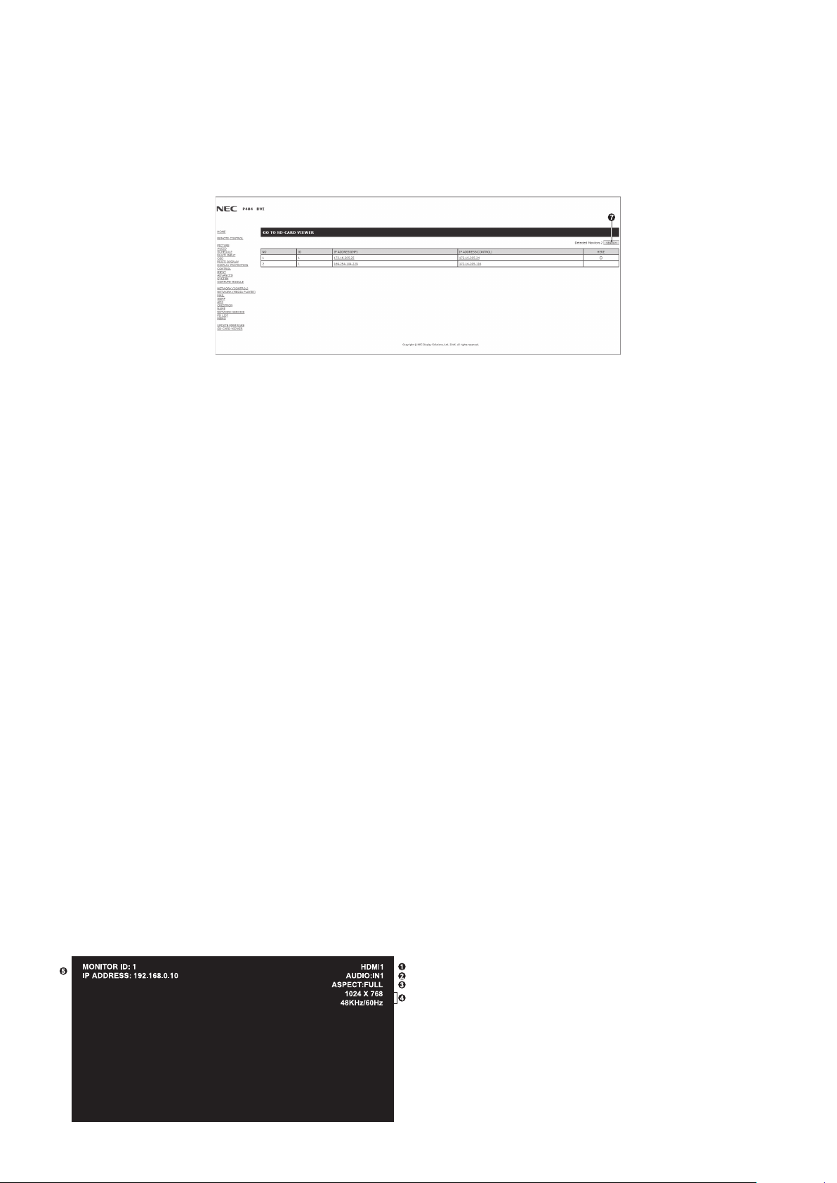
7. Connect to the other monitor’s SD-CARD VIEWER then open them.
By running the SEARCH, as described on the previous page, this window shows all compatible monitors on the same
network as the current monitor.
To open the other monitor’s web page in a new tab, right-click on its IP address. To open the other monitor’s web page in
a new window, left-click on its IP address.
Using CONTENTS COPY
You can copy all data saved in a USB storage device or saved in a shared folder, which is set in the connected computer or a
server, to a microSD memory card.
For copying shared folder data, please set SHARED FOLDER SETTINGS (See page 22) first.
1. Select CONTENTS COPY at the top screen of the Media Player.
2. Select a USB storage device or a folder.
3. Select OK to start copying. All data saved in the folder or device is copied to the microSD memory card and the original data
saved in the microSD memory card is deleted.
NOTE: “Out of disk space” is displayed if the microSD memory card storage capacity is not enough to copy selected folders.
When contents copy has occurred, previous data that was saved in the microSD memory card is deleted.
Only devices connected to the monitor are shown.
When the monitor is copying a folder, the LED indicator blinks in red.
When the monitor is in this condition, do not eject the microSD memory card from the monitor and do not turn off the
monitor’s main power. Ejecting the microSD card or turning off the monitor while copying files may corrupt the data.
If you press the STANDBY button on the remote control or the POWER button on the monitor while the LED indicator
is blinking in red, the monitor goes to standby after completing the folder copy.
Using Emergency contents
In case of emergency sends a command to the monitor, from a computer connected to the monitor, to play the emergency
contents folder. Please create an EMERGENCY CONTENTS folder as a root folder in the microSD memory card that is
connected to the monitor.
Instructions for the EMERGENCY CONTENTS can be found on the CD included with the monitor. The file is called
“External_control.pdf”.
Information OSD
TheInformationOSDprovidesinformationsuchas:InputSource,PictureSize,etc.
Press the DISPLAY button on the remote to bring up the Information OSD.
H
A
Input name
B
Audio input name
C
Picture aspect
D
Input Signal Information
E
Communication Info

English-25
English
Picture Mode
Select from five different picture modes, either via the OSD menu item PICTURE MODE or using the PICTURE MODE button
on the wireless remote control.
For DisplayPort, VGA (RGB), HDMI1, HDMI2, HDMI3
HIGHBRIGHT STANDARD sRGB CINEMA CUSTOM1 CUSTOM2
For VGA (YPbYr), VIDEO, MP
HIGHBRIGHT
STANDARD CINEMA CUSTOM1 CUSTOM2
PRESET types
PRESET PURPOSE
HIGH BRIGHT
Highest brightness setting.
STANDARD
Standard setting.
sRGB
The standard color space used for the Internet, Windows
®
operating systems and digital cameras. Recommended
setting for general color management.
CINEMA
A setting that boosts dark tones; best suited for movies.
CUSTOM
Custom setting.
English-26
OSD (On-Screen-Display) Controls
NOTE: Some functions may not be available depending on the model or optional equipment.
PICTURE:
PICTURE MODE
BRIGHTNESS
GAMMA
COLOR
CONTRAST
SHARPNESS
ADJUST
COLOR SYSTEM
INPUT RESOLUTION
ASPECT
ADVANCED
RESET
HIGHBRIGHT
STANDARD
sRGB
CINEMA
CUSTOM1
CUSTOM2
Goto Adjustment
Select
Return Close
MULTI-INPUT
Input source
Main Menu Icons
Main Menu Item
Sub Menu
Key Guide
Adjustment Settings
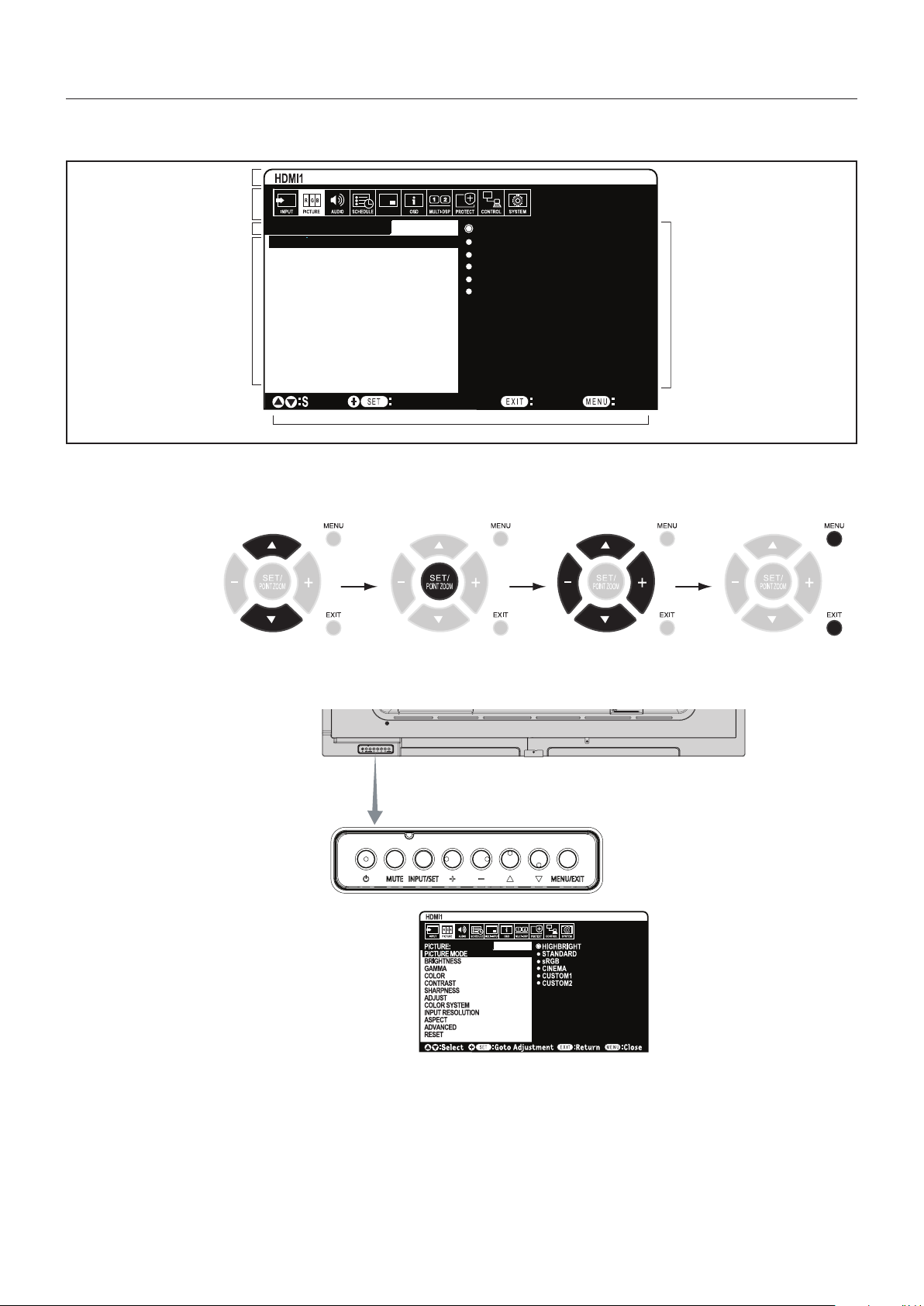
Remote Control
Press UP or DOWN
to navigate to a
sub-menu.
Press SET/POINT
ZOOM to select an
option.
Press UP or DOWN,
PLUS or MINUS to select
the function or setting to
be adjusted.
Press MENU or EXIT.
Press UP or DOWN
to navigate to a
sub-menu.
Press INPUT to
select an option.
Press UP or DOWN, PLUS
or MINUS button to select.
Press EXIT
Control Panel
OSD screen
English-27
English
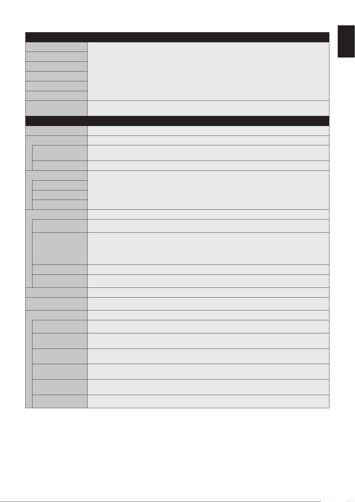
OSD Settings
INPUT
DisplayPort Select input signal.
HDMI1
HDMI2
HDMI3
VGA (RGB/YPbPr)
VIDEO
MP Displays images or movies saved in microSD memory card or USB storage device. Please refer to the Media
Player setting (See page 18).
PICTURE
PICTURE MODE Select picture mode: [HIGHBRIGHT], [STANDARD], [sRGB], [CINEMA], [CUSTOM1], [CUSTOM2]. See page 25.
BRIGHTNESS
BACKLIGHT Adjusts the overall image and background brightness. Press + or - to adjust.
NOTE: When MODE1 or MODE2 is selected in ROOM LIGHT SENSING, this function cannot be changed.
BRIGHTNESS*
1,
*
4
Adjusts the image brightness in relationship to the background. Press + or - to adjust.
GAMMA*
1
Select a monitor gamma correction for best picture quality. Selection depends on the desired usage.
NATIVE Gamma correction is handled by the LCD panel.
2.2 Typical monitor gamma for use with a computer.
2.4 Good for video (DVD, etc.)
COLOR*
1
COLOR*
2,
*
4
ExceptforVGA (RGB) input
Adjusts the color depth of the screen. Press + or - to adjust.
COLOR
TEMPERATURE*
2
Adjusts the color temperature of the entire screen. A low color temperature will result in a reddish screen. A high
color temperature will make the screen bluish. If TEMPERATURE needs further adjustment, the individual R/G/B/
levels of the white point can be adjusted. To adjust the R/G/B levels, set CUSTOM as COLOR TEMP selection.
NOTE: Predefined 6500k is set as picture mode, a color temperature of 6500k is predefined so it cannot be
changed.
COLOR CONTROL*
4
Adjusts the hue of the Red, Yellow, Green, Cyan, Blue and Magenta.
HUE*
4
MP, VIDEO inputs only
Adjusts the hue of the screen. Press + or - to adjust.
CONTRAST*
1,
*
4
Adjusts the image brightness in relationship to the input signal. Press + or - to adjust.
SHARPNESS*
2,
*
4
ExceptforVGA (RGB) input
Adjusts the crispness of the image. Press + or - to adjust.
ADJUST
AUTO SETUP
VGA (RGB) input only
AutomaticallyadjustsScreenSize,Hposition,Vposition,Clock and Phase.
AUTO ADJUST
VGA (RGB) input only
Please use ON normally. When you select OFF, H Position, V Position and Phase are not adjusted automatically
when new timing is detected.
H POSITION*
3
VGA (RGB), VGA (YPbPr) inputs only
ControlsthehorizontalpositionoftheimagewithintheDisplayareaoftheLCD.
Press + to move right. Press - to move left.
V POSITION*
3
VGA (RGB), VGA (YPbPr) inputs only
Controls the vertical position of the image within the Display area of the LCD.
Press + to move up. Press - to move down.
CLOCK
VGA (RGB) input only
Press+toexpandthewidthoftheimageontherightofthescreen.
Press - to narrow the width of the image on the left.
PHASE
VGA (RGB) input only
Adjusts the visual “noise” on the image.
*1: This function is not available when sRGB is selected at PICTURE MODE.
*2: This function is not available in HDMI/DisplayPort MODE when RGB is selected or when AUTO is selected and the input signal is RGB.
*3: This function is not available when 1:1 is selected as ASPECT.
*4: This function is not available for still image by MP input.
English-28
COLOR SYSTEM
VIDEO input only
The selected Color System depends on the video format of the input signal.
AUTO
NTSC Automatically chooses Color System setting based on input signal.
PAL
SECAM
4.43 NTSC
PAL-60
INPUT RESOLUTION
VGA (RGB) input only
Selects one of the following pair of resolutions as the input signal priority:
1366x768or1280x768or1024x768(verticalresolution768)
ASPECT*
1
Select the aspect ratio of the screen image.
NOTE: When the ASPECT is ZOOM, the image will be changed to FULL image before TILE MATRIX, and then
start TILE MATRIX. After TILE MATRIX, the ASPECT will be returned to the previous ASPECT or set ASPECT
during TILE MATRIX.
If you change H POSITION and V POSITION settings with a reduced image, the image would not be changed.
If SCREEN SAVER is set, the ASPECT setting automatically changes to FULL from what you set. Once SCREEN
SAVER is off the ASPECT setting will go back to the setting that you originally set.
This function is not available when MOTION in SCREEN SAVER is active.
When the ASPECT is set to ZOOM while TILE MATRIX is set to active, after releasing TILE MATRIX or ZOOM
will be active.
POINT ZOOM function has limitations, please refer to POINT ZOOM (See page 49).
NORMAL Shows the aspect ratio as it is sent from the source.
FULL Fills the entire screen.
WIDE Expandsa16:9letterboxsignaltolltheentirescreen.
1:1 Showstheimageina1by1Pixelformat.
ZOOM Expands/reducestheimage.
NOTE:Theareasoftheexpandedimagethatareoutsideoftheactivescreenareaarenotshown.Thereduced
image may have some image degradation.
ZOOM Maintainstheaspectratiowhilezooming.
HZOOM Horizontalzoomvalue.
VZOOM Verticalzoomvalue.
H POS Horizontalposition.
V POS Vertical position.
ADVANCED
OVER SCAN*
2
HDMI1, HDMI2, HDMI3, DisplayPort,
VGA (YPbPr), VIDEO inputs only
Some video formats may require different scanning modes in order to best display the image.
AUTO Imagesizeissetautomatically.
NOTE: This function is not available if input signal is VGA (YPbPr), VIDEO or MP.
ON Imagesizeislargerthanwhatcanbedisplayed.Theimageedgewillappearcropped.
Approximately95%oftheimagewillbeshownonthescreen.
OFF Imagesizestayswithinthedisplayarea.Thewholeimageisdisplayedonthescreen.
NOTE: When you use a computer with HDMI out, please set “OFF”.
NOISE REDUCTION
VIDEO input only
Adjusts the amount of noise reduction. Press + or - to adjust.
TELECINE*
2
HDMI1, HDMI2, HDMI3, DisplayPort,
VIDEO, VGA (YPbPr) inputs only
Automatically senses the sources frame rate for optimal picture quality.
ADAPTIVE
CONTRAST*
2,
*
3
HDMI1, HDMI2, HDMI3, DisplayPort,
VIDEO, VGA (YPbPr), MP inputs only
Sets the level of adjustment for dynamic contrast.
If HIGH is set, the image is displayed clearly but it makes brightness unstable due to the wide gap of contrast
variation.
RESET Resets all “PICTURE” settings back to factory settings exceptfor PICTURE MODE.
*1:ExceptforMP.
*2: This function is not available in HDMI/DisplayPort MODE when RGB is selected or when AUTO is selected and the input signal is RGB.
*3: This function is not available for still image by MP input.
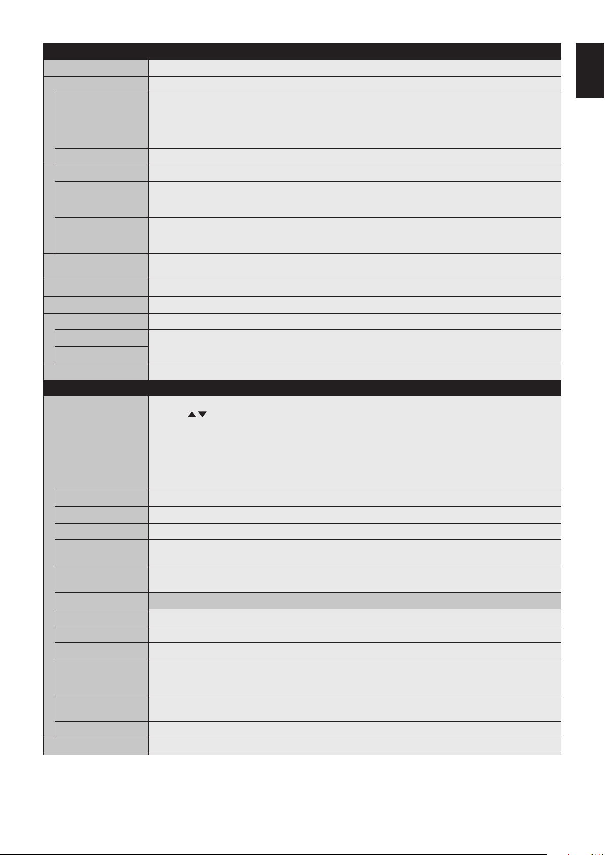
English-29
English
AUDIO
VOLUME Increase or decrease output volume level.
BALANCE
BALANCE Select STEREO or MONO for the audio output.
If you select STEREO, adjust the L/R volume balance.
Press the + button to move the stereo sound image to right.
Press the - button to move the stereo sound image to left.
NOTE: BALANCE is not available if MONO is set at STEREO/MONO.
SURROUND Artificial surround sound.
EQUALIZER
TREBLE Accentuate or reduce the high frequency range of audio signals.
Press the + button to increase TREBLE.
Press the - button to decrease TREBLE.
BASS Accentuate or reduce the low frequency sound.
Press the + button to increase BASS.
Press the - button to decrease BASS.
AUDIO INPUT Selects the audio input source: [IN1], [IN2], [DisplayPort], [HDMI1], [HDMI2], [HDMI3], [MP].
NOTE: [IN1] and [IN2] are not available if MP is set in INPUT.
LINE OUT Selecting VARIABLE enables control of the line out level with the VOLUME button.
INTERNAL SPEAKER Selecting OFF enables internal speaker output is turned off.
AUDIO DELAY
AUDIO DELAY Activate a delay time to output the audio signal. The DELAY TIME can be set between 0 and 100 milliseconds.
Set to ON to activate this function.
DELAY TIME
RESET ResetsallAUDIOoptionsbacktofactorysettings,exceptforVOLUME.
SCHEDULE
SCHEDULE SETTINGS Creates a working schedule for the monitor.
Press the , + - buttons to navigate and change the schedule settings. Press the SET/ZOOM on the remote
or Input change buttons on the monitor to select settings.
NOTE: Please set DAY & TIME before configuring the SCHEDULE SETTINGS.
When the SCHEDULE SETTINGS window is closed, any schedules that you set are saved.
If schedules are set for the same time, higher SETTINGS numbers are given the priority.
If OFF TIMER is ON, SCHEDULE SETTINGS is not available.
When you select an invalid input signal or picture mode, it will display in red. While the SCHEDULE SETTINGS
window is open, schedules are not operated. Also, see page 36.
SETTINGS Set ON to activate the schedule. Maximum30schedulesareset.
POWER Setting for the monitor power. Please set ON or OFF for each schedule.
TIME Set the schedule operation time. If there is no specific time for the schedule set [--].
INPUT Set the input signal for the schedule. To keep the input signal that is active when the schedule starts set [--].
When you set INPUT, please select ON at POWER.
PIC. MODE Set the picture mode for the schedule. To keep the picture mode that is active when the schedule starts set [--].
When you set PIC. MODE, please select ON at POWER.
Select one item from below (only one item is available).
DATE Select this setting if the schedule is for one day schedule or irregular schedules.
EVERY DAY Select this setting if the schedule is repeating every day.
EVERY WEEK Select this setting if the schedule is repeating every week.
WEEKDAY Select this setting if the schedule is on a weekday.
This item is set by the WEEKEND and the HOLIDAY settings. A day, which is not selected at WEEKEND and
HOLIDAY setting, is set as a weekday.
WEEKEND Select this setting if the schedule is on a weekend.
Schedule operates on the date that is set at WEEKEND SETTINGS.
HOLIDAY Schedule operates on the date that is set at HOLIDAY SETTINGS.
SCHEDULE LIST List of working schedules. Displays up to 30 schedules.
English-30
HOLIDAY SETTINGS
No. Creates holiday schedule for the monitor.
YEAR
MONTH
DAY
WEEK
Set YEAR and MONTH.
Select DAY or WEEK.
DAY: Set a day.
WEEK: Set a week and the day of the week.
If you set [--] at MONTH or YEAR, every month or year of the day you set is select as a holiday.
END DAY Set the end of holiday date. If you schedule beyond a year, please separate the schedule per year.
NOTE: If DAY is not set, END DAY is not available. If your holiday setting includes [--] for year or month,
END DAY is not available.
SET/DELETE Sets or deletes a schedule.
WEEKEND SETTING
WEEKEND Set the day of the week.
DATE & TIME Sets the date, time, and daylight savings region. Date & time must be set in order for the “SCHEDULE” function
to operate. See page 29.
NOTE: If the monitor’s main power has been turned off for two weeks, the DATE & TIME setting goes back to the
default setting and the clock function stops working.
YEAR Sets the year for the real-time clock.
MONTH Sets the month for the real-time clock.
DAY Sets the day for the real-time clock.
TIME Sets the time for the real-time clock.
CURRENT DATE TIME Shows the current date and time.
DAYLIGHT SAVING Sets daylight savings on or off.
NOTE: Please set the TIME & DATE setting first if you change the DAYLIGHT SAVING setting.
DAYLIGHT SAVING If ON is selected, please set daylight savings settings below.
BEGIN MONTH Set daylight savings beginning date.
END MONTH Set daylight savings ending date.
TIME DIFFERENCE Set the time difference.
OFF TIMER Set the monitor to power off after a preset time period. A time period between 1 to 24 hours may be set.
NOTE: SCHEDULE is not available if OFF TIMER is ON.
RESET Resets the following settings within the SCHEDULE menu back to factory setting: DATE & TIME and DAYLIGHT
SAVING.
MULTI INPUT
INPUT DETECT Selects the method of input detection the monitor uses when more than one signal source is connected.
NONE The Monitor will not search for signals at the other video input ports.
FIRST DETECT When the current video input signal is not present, the monitor searches for a video signal from another video
input port. If a video signal is present in the other input, the monitor switches from the current video source to this
active video source automatically.
The monitor will not look for any other video signals while the current video source is present.
CUSTOM DETECT Sets the priority of input signals.
When CUSTOM DETECT is selected, the monitor searches on preset inputs only.
When you use digital input (DisplayPort, HDMI1, HDMI2 and HDMI3), other digital input is not detected.
When you use analog input (VGA or VIDEO), other analog input is not detected.
English-31
English
TERMINAL SETTINGS
VGA MODE Selects RGB or YPbPr for VGA input.
DisplayPort BIT RATE Select RBR or HBR.
VIDEO LEVEL AUTO: Automatically sets input signals by adjusting connected equipment.
RAW: For computer settings. Show all input signals of 0-255 gray levels.
EXPAND:Foraudio-visualequipmentsettings.Expandstheinputsignalsfrom16-235graylevelsto0-255gray
levels.
NOTE: This function is available only in HDMI or DisplayPort and is selected at INPUT SIGNAL.
HDMI/DisplayPort
MODE
This function is available in HDMI or DisplayPort input.
AUTO: Automatically switches to RGB or YUV by detecting the internal information of the input signal.
RGB: For RGB in the input signal (e.g. Video output from a connected computer).
YUV: For YUV (YPbPr/YCbCr) in the input signal.
RESET Resets MULTI INPUToptionsbacktofactorysettings,except for INPUT DETECT (priority of input signals only)
and DisplayPort BIT RATE.
OSD
LANGUAGE Select the language used by the OSD.
ENGLISH
DEUTSCH
FRANÇAIS
ITALIANO
ESPAÑOL
SVENSKA
РУССКИЙ
OSD TIME Turns off the OSD after a period of inactivity. The preset choices are 10-240 seconds.
OSD POSITION Selects the location where the OSD appears on the screen.
INFORMATION OSD Selects whether the Information OSD is displayed or not. The Information OSD will appear when the input signal
or input source changes. The Information OSD will also give a warning when no signal is detected or the signal is
out of range.
An interval between 3 to 10 seconds is selectable for the Information OSD to appear.
COMMUNICATION
INFO.
The MONITOR ID and IP ADDRESS will appear when the remote control Display button is pressed.
OSD ROTATION Determines the OSD orientation between landscape and portrait.
LANDSCAPE Shows the OSD in landscape orientation.
PORTRAIT Shows the OSD in portrait orientation.
NOTE: If PORTRAIT is set, CLOSED CAPTION is not available.
KEY GUIDE Key guide is shown when the OSD menu is displayed.
MEMO Defines a title and a message via HTTP server. See page 46.
INPUT NAME You can create a name for the INPUT currently being used.
Max:14characters,includingSpace,A-Z,0-9,andsomesymbols.
CLOSED CAPTION
VIDEO input only
Activates closed captioning.
NOTE: This function is released if the following function is activated: PORTRAIT in OSD ROTATION, TILE
MATRIX, SCREEN SAVER, STILL, POINT ZOOM.
RESET Resets the following settings within the OSD menu back to factory setting:
OSD TIME, OSD POSITION, INFORMATION OSD, OSD TRANSPARENCY, CLOSED CAPTION.
English-32
MULTI DISPLAY
TILE MATRIX*
1
(ExceptforMP)
Allowsoneimagetobeexpandedanddisplayedovermultiplescreens(upto100)throughadistribution
amplifier.
NOTE: Low resolution is not suitable for tiling to a large number of monitors. You can operate without a
distribution amplifier at a lower number of screens.
This function is released when selecting SCREEN SAVER exceptforNONE.
ZoomwillnotworkwhenTileMatrixisactivated.
When“ZOOM”isselectedinASPECTwhileexecutingTILEMATRIX,thesettingwillbeappliedaftercompleting
the TILE MATRIX.
When TILE MATRIX is active the following functions are not available: CLOSED CAPTION, STILL,
POINT ZOOM. Please refer to the POINT ZOOM function for more detail (see page 49).
If Media Player contents are played while TILE MATRIX is active, the image play timing might have a gap within
monitors.
This function is not available when SCREEN SAVER is active.
H MONITORS Numberofmonitorsarrangedhorizontally.
V MONITORS Number of monitors arranged vertically.
POSITION Select which section of the tiled image to be displayed on the monitor.
TILE COMP Turns the TILE COMP feature on. IfYESissettotheTILECOMP,youcanadjustadisplayedimagesizeand
position by pressing the + button or the - button on the remote control.
ENABLE Enables the TileMatrixsettings.
TILE MATRIX MEM When “INPUT” is selected, the TILE MATRIX setting is applied to each signal input.
COMMON All settings in the TILE MATRIX are saved for all signal inputs.
INPUT All settings in the TILE MATRIX are saved for the selected signal input.
ID CONTROL Sets the monitor ID number from 1-100 and group ID from A-J.
The Group ID is made of multiple selections. Also see page 37.
RESET Resets all settings within the MULTI DISPLAY menu back to factory setting.
DISPLAY PROTECTION
POWER SAVE Set ENABLE or DISABLE. If you set it to ENABLE, set how long the monitor waits to go into power save mode
after signal is lost. For more details, please check the Power Indicator (See page 35).
AUTO POWER SAVE
TIME SETTING
Set the time when the monitor goes into auto power save mode after signal is lost.
QUICK TURN ON When ENABLE is selected, the monitor will quickly return to the ON state when a signal is detected. Enabling this
option increases standby power consumption.
STANDBY USB
POWER
When ENABLE is selected, you can use USB port for power supply in standby mode.
POWER SAVE MESSAGE When the monitor goes into power save mode, a message is displayed when ON is selected.
HEAT STATUS Shows the actual status of the backlight and temperature sensors.
SCREEN SAVER Use the SCREEN SAVER function to reduce the risk of Image Persistence.
NOTE: When the screen saver is activated, the image will be changed to FULL image. After the screen saver
stops, the image will be reproduced again with the current ASPECT setting.
When the SCREEN SAVER is set to active, STILL, POINT ZOOM, TILE MATRIX, CLOSED CAPTION are not
available.
BACKLIGHT The brightness of the backlight is decreased when “ON” is selected.
NOTE: Do not select this function when ROOM LIGHT SENSING is set to MODE1 or MODE2.
MOTION Thescreenimageisslightlyexpandedandmovesin4directions(UP,DOWN,RIGHT,LEFT)at user determined
intervals.Youcansetintervaltimeandzoomratio.
SIDE BORDER COLOR Adjusts the color of the side borders when a 4:3 image is reproduced.
By pressing the + button on the remote control, the side borders will become brighter.
By pressing the - button, the side borders will become darker.
Background color of the Media Player window is also changed.
POWER ON DELAY Adjusts the delay time between being in “standby” mode and entering “power on” mode.
DELAY TIME “POWER ON DELAY” can be set between 0 and 50 seconds.
LINK TO ID When “ON” is selected, the delay time is linked with the Monitor ID. It takes more time when there are a large
number of IDs.
ALERT MAIL Set ON to activate alert mail. Please refer to Mail Setting (See page 44).
RESET Resets all settings within the DISPLAY PROTECTION menu back to factory setting exceptfor POWER ON
DELAY.
*1:ExceptforMP.
English-33
English
CONTROL
NETWORK
INFORMATION
Shows the current network settings.
LAN NOTE: When changing any LAN settings, you need to wait several seconds until modified LAN settings are
applied.
IP SETTING Enabling this option automatically assigns an IP address to the monitor from your DHCP server.
Disabling this option allows you to enteraxed IP address and subnet mask data obtained from your network
administrator.
NOTE: Consult your network administrator for the IP address when AUTO is selected for [IP SETTING].
IP ADDRESS Set your IP address for the monitor connected to the network when MANUAL is selected for [IP SETTING].
SUBNET MASK Set your subnet mask data for the monitor connected to the network when MANUAL is selected for
[IP SETTING].
DEFAULT GATEWAY Set your default gateway for the monitor connected to the network when MANUAL is selected for [IP SETTING].
NOTE: Enter [0.0.0.0] to delete the setting.
DNS Set the IP addresses of DNS servers.
AUTO: The DNS server, which is connected with the monitor, will automatically assign its IP address.
MANUAL: Manually enter the IP address of the DNS server which is connected with the monitor.
DNS PRIMARY Enter the primary DNS server settings of the network connected with the monitor.
NOTE: Enter [0.0.0.0] to delete the setting.
DNS SECONDARY Enter the secondary DNS server settings of the network connected with the monitor.
NOTE: Enter [0.0.0.0] to delete the setting.
CHANGE PASSWORD Allows the security password to be changed.
The factory preset password is 0000.
SECURITY
PASSWORD Input a security password.
SECURE MODE
OFF The security password is not required when the monitor power is on.
START-UP LOCK The security password is required when the monitor power is on.
CONTROL LOCK The security password is required when a remote control button or a control button on the monitor is pressed.
BOTH LOCK The security password is required when either the monitor is powered on, or a remote control button or a control
button on the monitor is pressed.
IR LOCK SETTINGS Prevents the monitor from being controlled by the wireless remote control.
When ACTIVATE is selected, all settings are activated.
NOTE: IR LOCK SETTINGS is a function intended only for the wireless remote control buttons. This function
does not lock out access to the buttons on the monitor. To return to normal operation, press the “DISPLAY” button
on the remote control and hold it down for more than 5 seconds.
MODE SELECT Selects the mode UNLOCK, ALL LOCK or CUSTOM LOCK.
UNLOCK All buttons on the remote control are available for normal operation.
ALL LOCK Locks all remote control buttons.
CUSTOM LOCK Selects which buttons to be locked from POWER, VOLUME, and INPUT button.
ExceptforCUSTOMLOCKsettings,otherbuttonsontheremotecontrolarelocked.
POWER: When LOCK is selected, the POWER button is locked.
VOLUME:WhenUNLOCKisselected,settheminimumandmaximumvolumebetweenVOL.0toVOL.100.
VOLUME (+) button and VOLUME (-) buttons are only available from the minimum volume to the
maximumvolumeyouset.
When LOCK is selected, VOLUME (+) button and VOLUME (-) buttons are locked.
INPUT: When UNLOCK is selected, choose up to three buttons from DisplayPort, HDMI1, HDMI2, HDMI3,
VGA (RGB/YPbPr), VIDEO, Media Player which you prefer to be unlocked.
The unselected buttons are locked. When LOCK is selected, all INPUT buttons are locked.
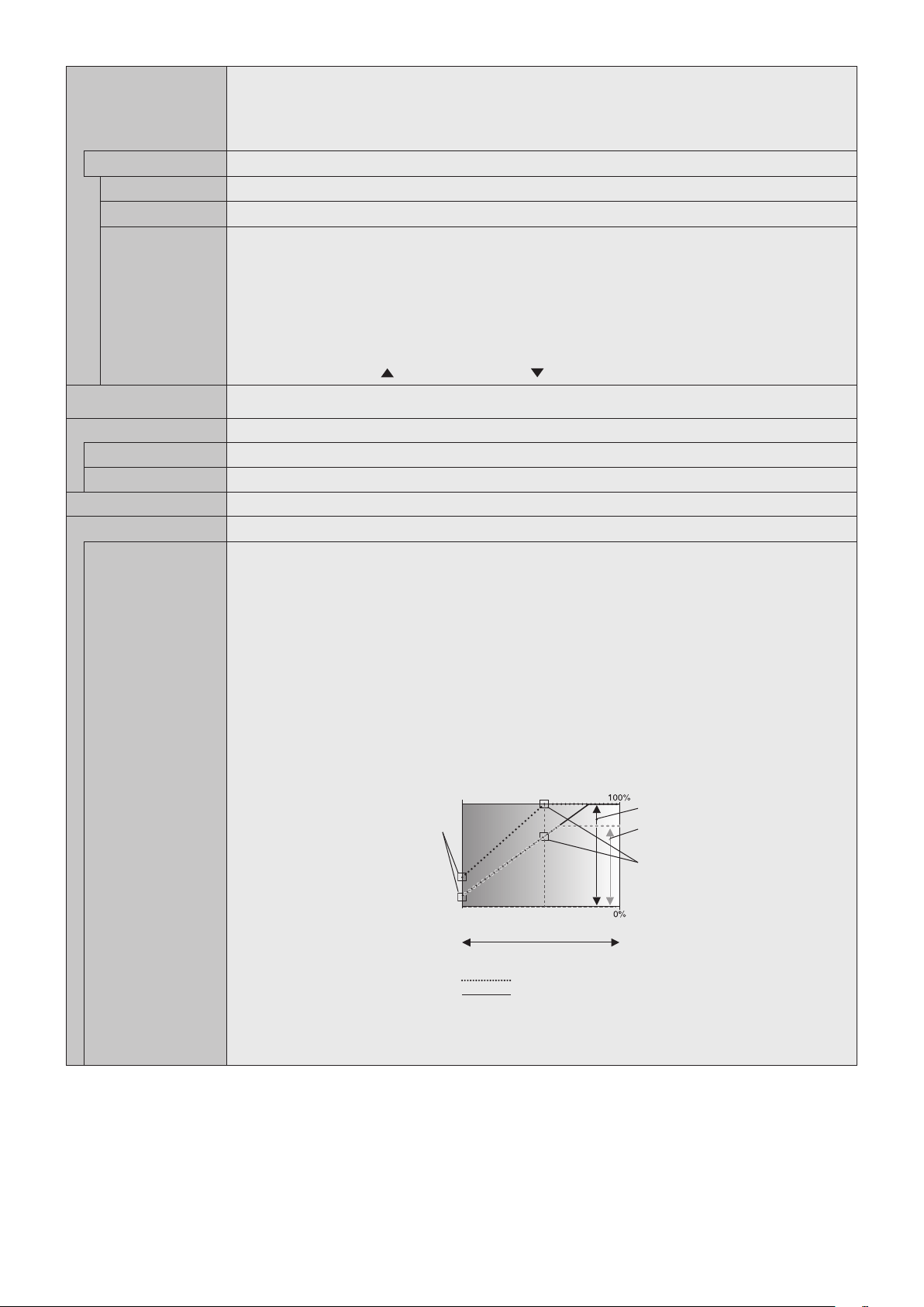
English-34
KEY LOCK SETTINGS
Prevents the monitor from being controlled by the buttons on the monitor.
When ACTIVATE is selected all of the settings are activated.
NOTE: KEY LOCK SETTINGS is a function intended only for the buttons of the monitor. This function does not
lock out access to all buttons on the remote control. To activate the control key lock function, press the power
button for more than 3 seconds. To resume user mode, press the power button for more than 3 seconds.
MODE SELECT
Selects the mode UNLOCK, ALL LOCK or CUSTOM LOCK.
UNLOCK
All buttons are available for normal operations.
ALL LOCK
Locks all remote control buttons.
CUSTOM LOCK
Selects which buttons to be locked from POWER, VOLUME, and INPUT button.
ExceptforCUSTOMLOCKsettings,otherbuttonsontheremotecontrolarelocked.
POWER: When LOCK is selected, the POWER button is locked.
VOLUME:WhenUNLOCKisselected,settheminimumandmaximumvolumebetweenVOL.0toVOL.100.
The PLUS button (+) and the MINUS button (-) are only available from the minimum volume to the
maximumvolumeyouset.
When LOCK is selected, the PLUS button (+) and the MINUS button (-) are locked.
INPUT: When UNLOCK is selected, the INPUT/SET button is unlocked.
CHANNEL: To lock channel buttons on the remote control, select it to LOCK then press ACTIVE,
the UP button (
) and the DOWN button ( ) are locked.
DDC/CI
VGA (RGB) Input only
ENABLE/DISABLE: Turns ON or OFF the two-way communication and control of the monitor.
PING Confirm successful connection with the network by communicating with a preset IP address.
IP ADDRESS Sets an IP ADDRESS for sending PING.
EXECUTE Checks a reply can be sent to the monitor or not from the IP ADDRESS by sending PING.
IP ADDRESS RESET Resets IP ADDRESS SETTINGS back to factory settings.
AUTO DIMMING
Adjusts the backlight of the LCD automatically depending on the amount of ambient light.
ROOM LIGHT
SENSING
The backlight of the LCD screen can be set to increase or decrease depending on the amount of ambient light
within the room. If the room is bright, the monitor becomes correspondingly bright. If the room is dim, then the
monitorwilldimaccordingly.Thepurposeofthisfunctionistomaketheviewingexperiencemorecomfortableto
the eye in a variety of lighting conditions.
NOTE: When ROOM LIGHT SENSING is set, BACKLIGHT and BACKLIGHT in SCREEN SAVER functions are
disabled.
Do not cover the room light sensing sensor when you use MODE1 or MODE2.
AMBIENT parameter setting
ROOM LIGHT SENSING in OSD, select MODE1 or MODE2 and set MAX LIMIT, IN BRIGHT and IN DARK in
each mode.
MAXLIMIT:Thisisthemaxlevelofbacklight,whichyouset.
IN BRIGHT: This is the backlight level that the monitor will go up to when the ambient light level is highest.
IN DARK: This is the level of backlight that the monitor will go down to when the ambient light level is low.
When the ROOM LIGHT SENSING is enabled the Backlight level of the screen changes automatically according
to the lighting conditions of the room (see figure below).
BACKLIGHT level set for
the monitor to use when
ambient lighting level is
low.
BACKLIGHT level set
for the monitor to use
when ambient lighting
level is high.
BACKLIGHT range
dark bright
room bright condition
Screen Backlight value by MODE2
IN DARK IN BRIGHT
Screen Backlight value by MODE1
Factory Setting
BACKLIGHT range when
set to MAX LIMIT.
MAX LIMIT: BACKLIGHT level is limited to your set level.
IN DARK: BACKLIGHT level set for the monitor to use when ambient lighting level is low.
IN BRIGHT: BACKLIGHT level set for the monitor to use when ambient lighting level is high.
English-35
English
POWER INDICATOR
POWER INDICATOR Turns the LED on or off. If OFF is selected, the LED will not glow when the LCD monitor is in active mode.
SCHEDULE
INDICATOR
Turns the LED on or off depending on a schedule activity which is set at “SCHEDULE SETTINGS”. If OFF is
selected, the LED will not glow even if a schedule is in active mode.
CEC* This function enables you to control the HDMI CEC compliant device connected via HDMI connector.
*: CEC is an abbreviation of Consumer Electronics Control.
CEC When ON is set, please set items below.
NOTE: If ON is selected, the below functions are activated.
When the connected HDMI CEC device receives a play command, the monitor synchronously turns on then
changes the input signal to HDMI. If the monitor has been turned on, when a connected HDMI CEC device
receives a play command, input signal is switched to HDMI.
The connected HDMI CEC devices are controlled by the wireless remote control supplied with the monitor.
Depending on the connected device, the device may not work properly.
AUTO TURN OFF When the monitor goes to standby via remote control or the power button on the monitor, a connected HDMI
CEC device go to standby synchronously.
NOTE: If the connected HDMI CEC device is recording, the device does not go into standby.
AUDIO RECEIVER Activates HDMI CEC audio amplifier. If YES is set, outputs the sounds of the connected HDMI CEC device from
the connected HDMI CEC audio amplifier. If YES is set, the internal speaker is set to mute.
NOTE: When an HDMI CEC audio amplifier is connected, set to YES.
Please set to NO if there is no connected HDMI CEC audio device to the monitor.
SEARCH DEVICE Searches the HDMI CEC device connected to the monitor. When search is successful, the connected HDMI CEC
device’s type and registered device name are shown. When search has been completed or failed, the SEARCH
DEVICE is set to NO automatically. To retry the SEARCH DEVICE, set it to YES again. After detecting HDMI
CEC devices, you can switch the device input by selecting the device.
RESET Resets all the settings within the CONTROL menu back to factory setting exceptfor LAN, CHANGE
PASSWORD, SECURITY and PING.
SYSTEM
MONITOR INFORMATION Shows the model name, serial number and firmware version of your monitor.
CARBON SAVINGS: Display the estimated carbon saving information in kg-CO2. The carbon footprint factor in
the carbon saving calculation is based on the OECD (2008 Edition).
CARBON USAGE: Display the estimated carbon usage information in kg-CO2. This is the arithmetic estimation,
not actual measurement value. This estimation is based without any options.
FIRMWARE Displays firmware version that is installed to the monitor.
MAC ADDRESS Displays the MAC ADDRESS.
FACTORY RESET All items are returned to factory shipment state.
NOTE: You can reset all items in all daisy chained monitors. Please be careful to avoid resetting all items
inadvertently.
Default values can be provided on request.
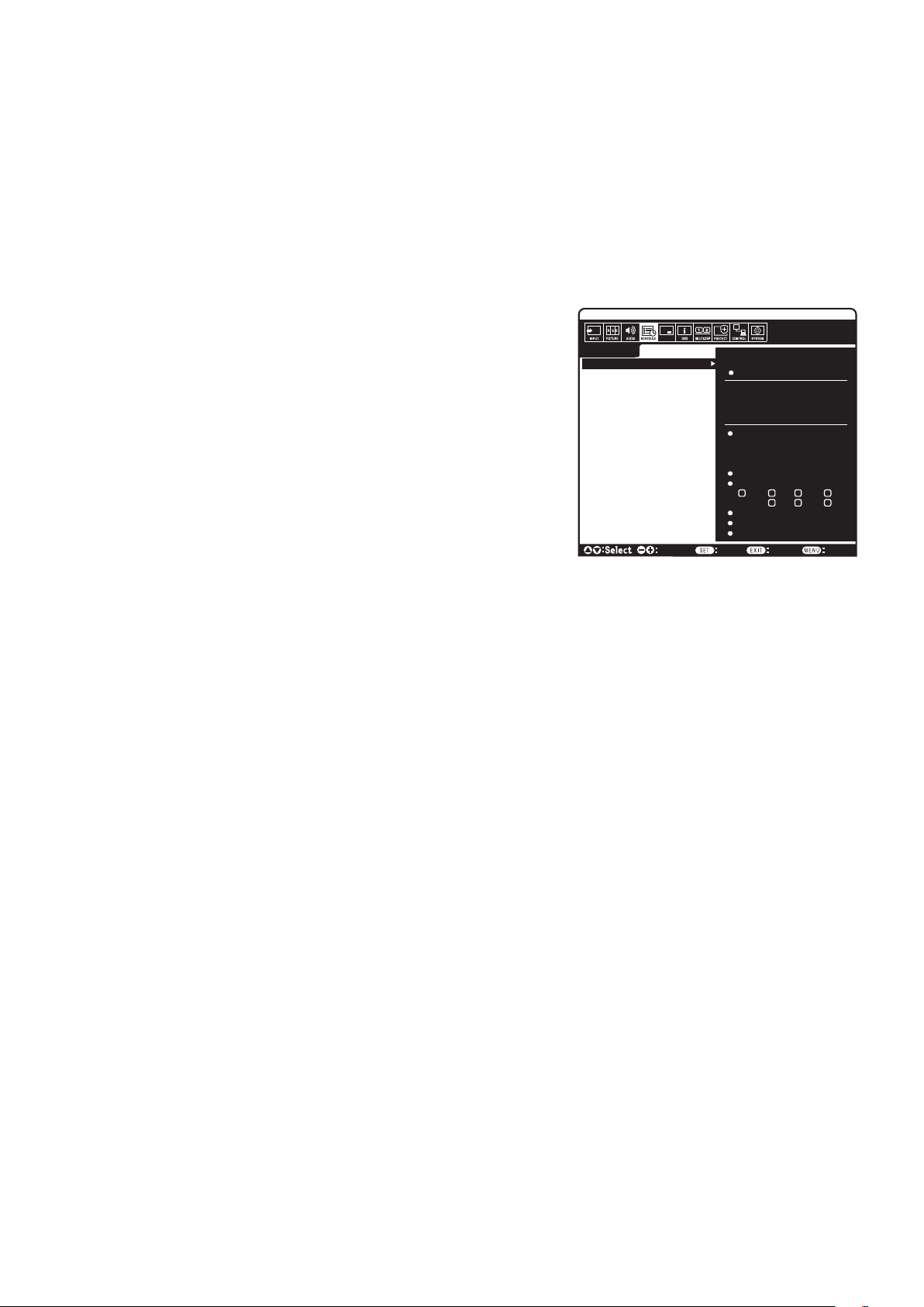
English-36
NOTE 1: CREATING A SCHEDULE
The schedule function allows the monitor to be set to power on or to be on standby at different times. Up to seven different schedules can be
programmed.
To program the schedule:
1. Enter the SCHEDULE menu. Highlight SCHEDULE SETTINGS using the up and down buttons. Press the SET/POINT ZOOM or the + button
toentertheSettingsmenu.HighlightthedesiredschedulenumberandpressSET/POINTZOOM.Theboxnexttothenumberwillturnyellow.
The schedule can now be programmed.
2. Use the down button to highlight the POWER. Use the + and - buttons to set ON. To set power off schedule, set OFF.
3. Use the down button to highlight the TIME. Use the + and - buttons to set the time.
4. Use the up and down arrows to highlight INPUT. Use the + and - buttons to choose the input source. Use the up and down arrows to highlight
PIC. MODE. Use the + and - buttons to choose the picture mode.
5. Use the down button to select DATE, EVERY DAY, EVERY WEEK, WEEKDAY,
WEEKEND or HOLIDAY. Push the SET/POINT ZOOM button on a menu which is
suitable for the schedule. If the schedule is to be run on a specific day, choose DATE
and press the SET/POINT ZOOM button. If the schedule is to be run every day, choose
EVERYDAYandpresstheSET/POINTZOOMbutton.ThecirclenexttoEVERYDAY
will turn yellow. If a weekly schedule is desired, choose the days of the week using the up
and down buttons and pressing SET/POINT ZOOM to select. Then highlight the EVERY
WEEK option and press SET/POINT ZOOM. Please set WEEKDAY, WEEKEND, or
HOLIDAY in the same manner.
The WEEKDAY, WEEKEND, and HOLIDAY settings are available under the SCHEDULE
setting (See page 29).
6. After a schedule is programmed, the remaining schedules can then be set. Press MENU
to leave the OSD or press EXIT to go back to the previous menu.
NOTE: If schedules are overlapping, the schedule with the highest number will have
priorityovertheschedulewiththelowestnumber.Forexample,schedule#7willhave
priorityoverschedule#1.
If a selected input or picture mode is not available now, the disabled input or picture mode is shown in red.
NOTE 2: IMAGE PERSISTENCE
PleasebeawarethatLCDTechnologymayexperienceaphenomenonknownasImagePersistence.ImagePersistenceoccurswhena
residual or “ghost” image of a previous image remains visible on the screen. Unlike CRT monitors, LCD monitors’ image persistence is not
permanent, but a still image being displayed for a long period of time should be avoided.
To alleviate image persistence, turn off the monitor’s main power or set it to standby for as long as the previous image was displayed. For
example,ifanimagewasonthemonitorforonehourandaresidualimageremains,themonitor’s main power should be turned off or set it to
standby for one hour to erase the image.
As with all personal display devices, NEC DISPLAY SOLUTIONS recommends displaying moving images and using a moving screen saver at
regular intervals whenever the screen is idle, or turn off the monitor’s main power or set it to standby when not in use.
Please set “SCREEN SAVER”, “DATE &TIME” and “SCHEDULE SETTINGS” functions to further reduce the risk of Image persistence.
For long life use as a Public Display
Image Sticking of LCD Panel
When an LCD panel is operated continuously for long hours, a trace of electric charge remains near the electrode inside the LCD and a
residual or “ghost” image of the previous image may be observed. (Image Persistence)
ImagePersistenceisnotpermanent,butwhenaxedimageisdisplayedforalongperiod,ionicimpuritiesinsidetheLCDareaccumulated
along the displayed image and may be permanent. (Image Sticking)
Recommendations
To prevent Image Sticking, and for longer life usage of the monitor, the following is recommended.
•Axedimageshouldnotbedisplayedforlongperiods.
•Whennotinuse,pleaseturnoffthemonitorviaremotecontrol,orusethe Power Management function of the PC, or use the built-in Schedule
Functions.
•Lower environmental temperatures prolong the lifespan of the monitor.
When a protective surface (glass, acrylic) is installed over the monitor’s screen surface, the monitor’s screen surface is located in an
enclosure, or if the monitorsarestacked,utilizethetemperaturesensorsinsidethemonitor.
To reduce the internal temperature, use the Screen Saver, the Power Management function of the PC and Low Brightness.
•Pleaseuse“ScreenSaverMode”ofmonitor.
SCHEDULE:
POWER: ON
TIME: 04 : 03
DVI
INPUT:
PIC. MODE: STANDARD
HDMI1
(MON) OCT.26.2015 12:37
SETTINGS:
SCHEDULE SETTINGS
SCHEDULE LIST
HOLIDAY SETTINGS
WEEKEND SETTINGS
DATE & TIME
DAYLIGHT SAVINGS
OFF TIMER
RESET
MONTH:
DAY:
1
Choose Mark
Return Close
DATE
YEAR:
JAN
01
2016
MON TUE WED THU
SAT SUNFRI
EVERY DAY
EVERY WEEK
HOLIDAY
WEEKDAY
WEEKEND
MULTI-INPUT
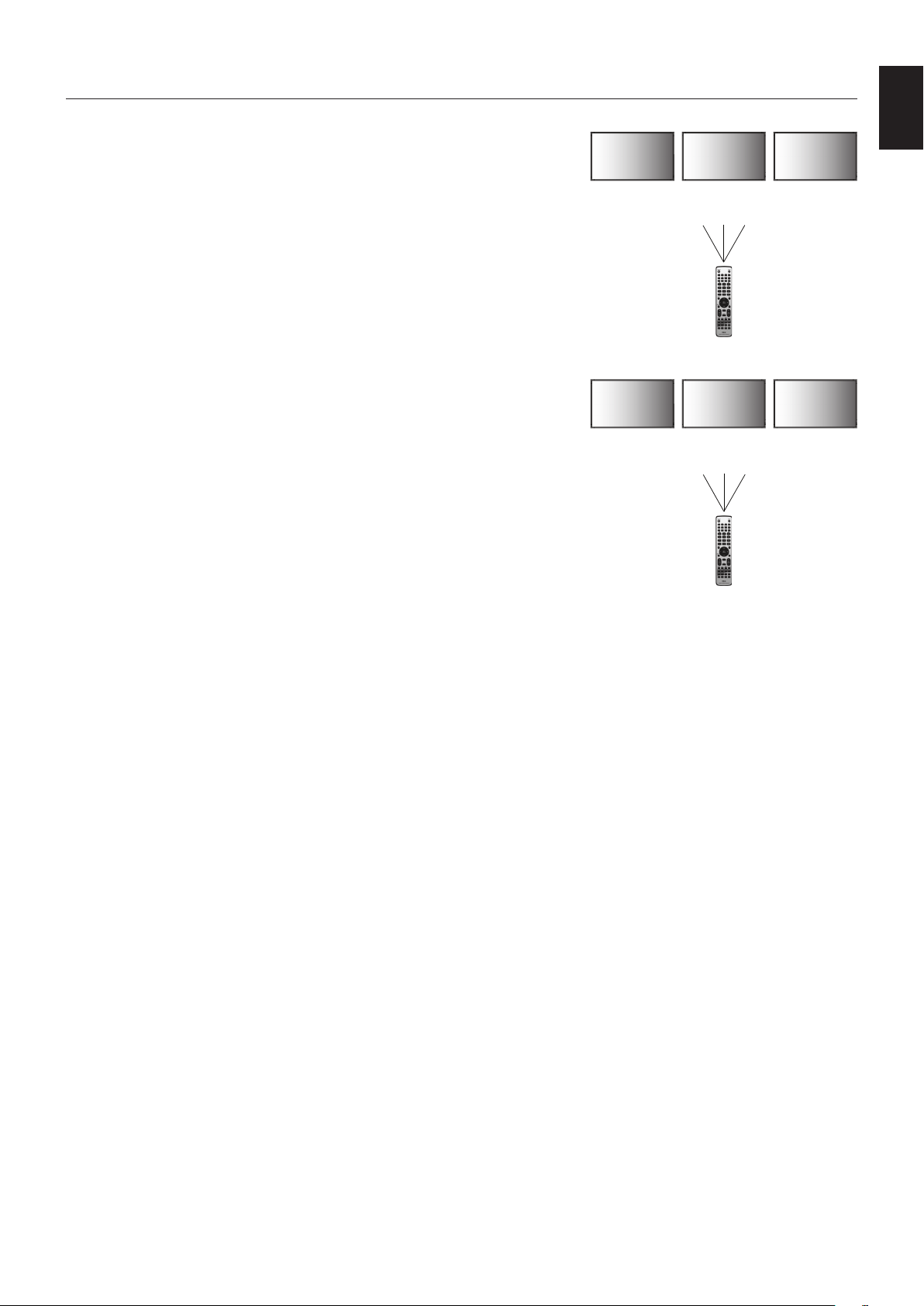
English-37
English
REMOTE CONTROL ID FUNCTION
REMOTE CONTROL ID
The remote control can be used to control up to 100 individual monitors using what is called
the REMOTE CONTROL ID mode. The REMOTE CONTROL ID mode works in conjunction
withtheMonitorID,allowingcontrolofupto100individualmonitors.Forexample,if
there are many monitors being used in the same area, a remote control in normal mode
would send signals to every monitor at the same time (see Figure 1). Using the remote in
REMOTE CONTROL ID mode will only operate one specific monitor within the group (see
Figure 2).
TO SET REMOTE CONTROL ID
While holding down the REMOTE ID SET button on the remote control, use the KEYPAD to
input the Monitor ID (1-100) of the monitor to be controlled via remote. The remote can then
be used to operate the monitor having that specific Monitor ID number.
When 0 is selected or when the remote control is in normal mode, all monitors will be
operated.
TO SET/RESET REMOTE CONTROL MODE
ID Mode - To enter ID Mode press the REMOTE ID SET button and hold down for
2 seconds.
Normal Mode - To return to Normal Mode press the REMOTE ID CLEAR button and hold
down for 2 seconds.
In order for this feature to work properly, the monitor must be assigned a unique Monitor ID
number. The Monitor ID number can be assigned under the MULTI DISPLAY menu in the
OSD (See page 32).
Point the remote control towards the remote sensor of the desired monitor and press the
REMOTE ID SET button. The MONITOR ID number is shown on the screen when your
remote control is in ID mode.
Use the remote to control all monitors in range
1. On the remote control, press and hold down the REMOTE ID SET button while using the keypad to input the REMOTE CONTROL ID
number “0”.
2. All monitors within range of the remote control will now respond to keypad press.
NOTE: When the REMOTE ID is set to “0”, pressing REMOTE ID SET will make all monitors, within range of the remote signal,
display their Monitor ID on screen. This way you can easily see what the monitor ID is if you want to control a single monitor,
as described below.
Use the remote control to operate a monitor that has a specific MONITOR ID number assigned to it
1. Set the MONITOR ID number for the monitor (See page 32). The MONITOR ID number can range from 1-100.
This MONITOR ID number allows the remote control to operate this specific monitor without affecting other monitors.
2. On the remote control, press and hold down the REMOTE ID SET button while using the keypad to input the REMOTE CONTROL ID number
(1-100). The REMOTE ID NUMBER should match the MONITOR ID number of the monitor to be controlled.
3. Point the remote control towards the remote sensor of the desired monitor and press the REMOTE ID SET button.
The MONITOR ID number is shown in red on the monitor.
If the REMOTE CONTROL ID is “0”, then all monitors in range will show their respective MONITOR ID number in red.
If the MONITOR ID number is shown in white on the monitor, the MONITOR ID number and the REMOTE CONTROL ID are not the same.
NOTE: The GROUP ID cannot be specified via the remote control.
Remote Control Functions
Monitor ID:1 Monitor ID:2 Monitor ID:3
Monitor ID:1 Monitor ID:2 Monitor ID:3
Remote does
not work
Remote does
not work
Remote works
Remote works Remote works Remote works
Figure 1
Remote in
Normal mode or
the REMOTE ID
is set to 0
Figure 2
Remote set up
to use REMOTE
ID:3
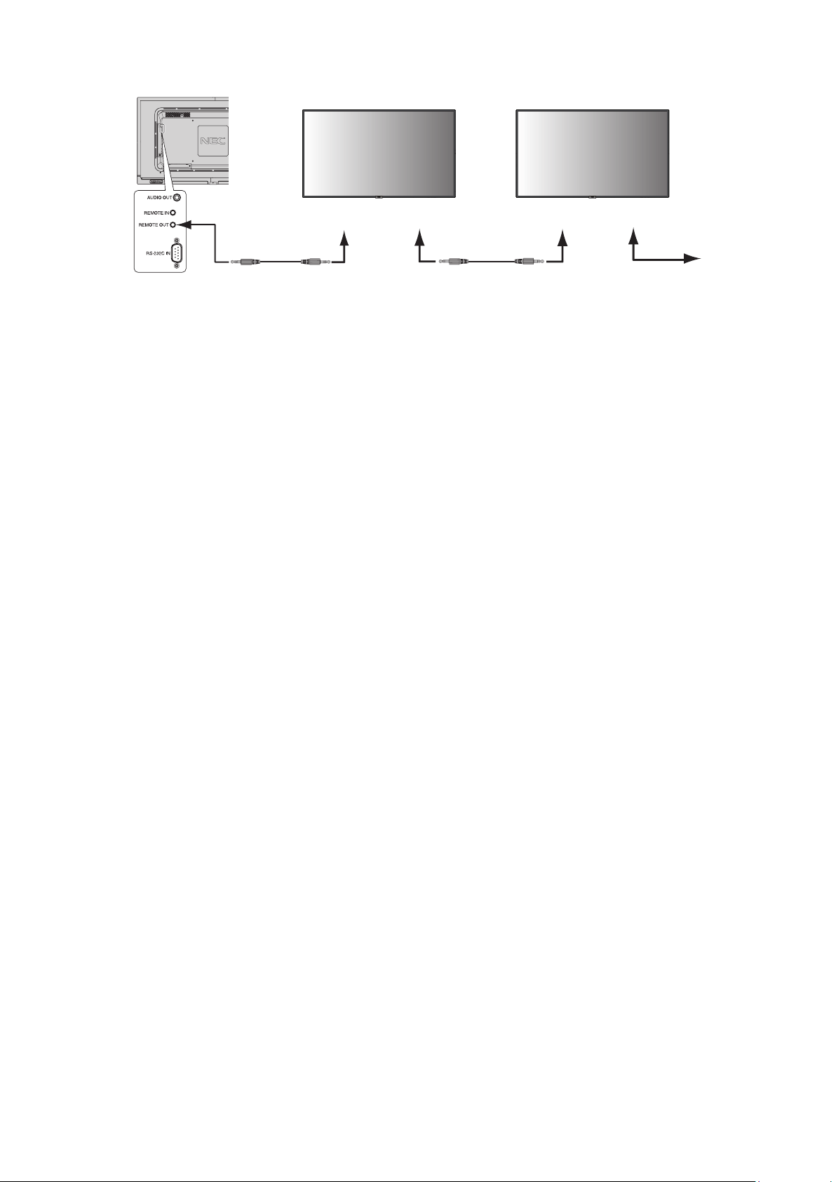
English-38
WIRED REMOTE CONTROL FUNCTION
You can control multiple monitors by connecting REMOTE IN/OUT with Stereo Mini plug cable (Ø 3.5 mm) [Not supplied].
Remote control cable
Remote IN
Remote control cable
Remote OUT Remote IN Remote OUT
NOTE: Turn off the main power switch before connect/disconnect Stereo Mini plug cable.
NOTE: Do not use this connector for any other purpose.
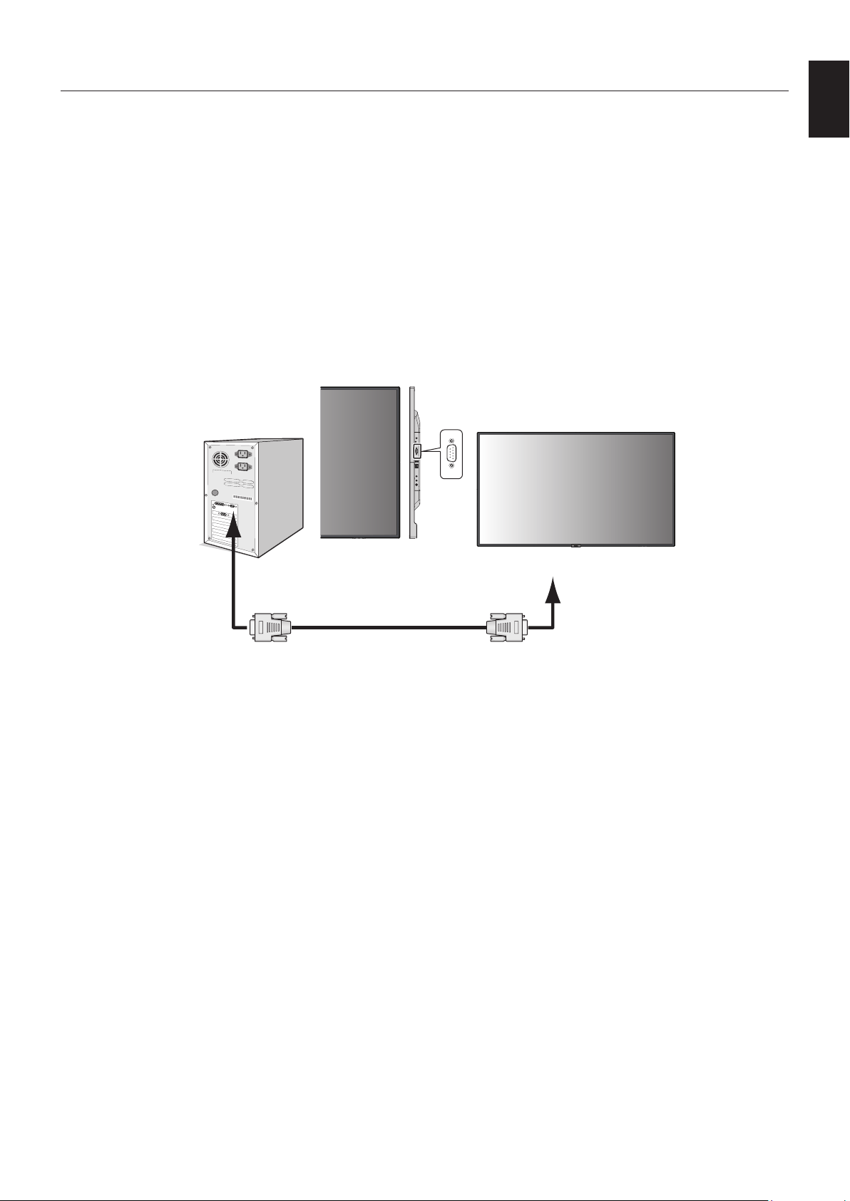
English-39
English
This LCD monitor can be controlled by connecting a personal computer with an RS-232C (reverse type) terminal.
Functions that can be controlled by a personal computer are:
•PowerONorstandby.
•Switchingbetweeninputsignals.
•SoundMuteONorOFF.
Connection
LCD Monitor + computer.
•Please turn off the monitor’s main power when connecting a computer to the monitor.
•Please turn on the connecting computer first then turn on the monitor’s main power.
If you turn on the computer and monitor in reverse order, the com port may not work.
•When controlling the monitor connected with an RS-232C cable, please refer to the Control command diagram (See page 47)
or see the “External_Control.pdf”leontheCD-ROM supplied with the monitor.
RS-232C Cable
Computer
RS-232C
NOTE: If your computer is equipped only with a 25-pin serial port connector, a 25-pin serial port adapter is required. Contact
your supplier for details.
For the pin assignment, please see “2) RS-232C input/output” on page 40.
To control a monitor, please use the control command. Instructions for the control command can be found on the CD included
withthemonitor.Theleiscalled“External_control.pdf”.
Controlling the LCD monitor via RS-232C Remote Control
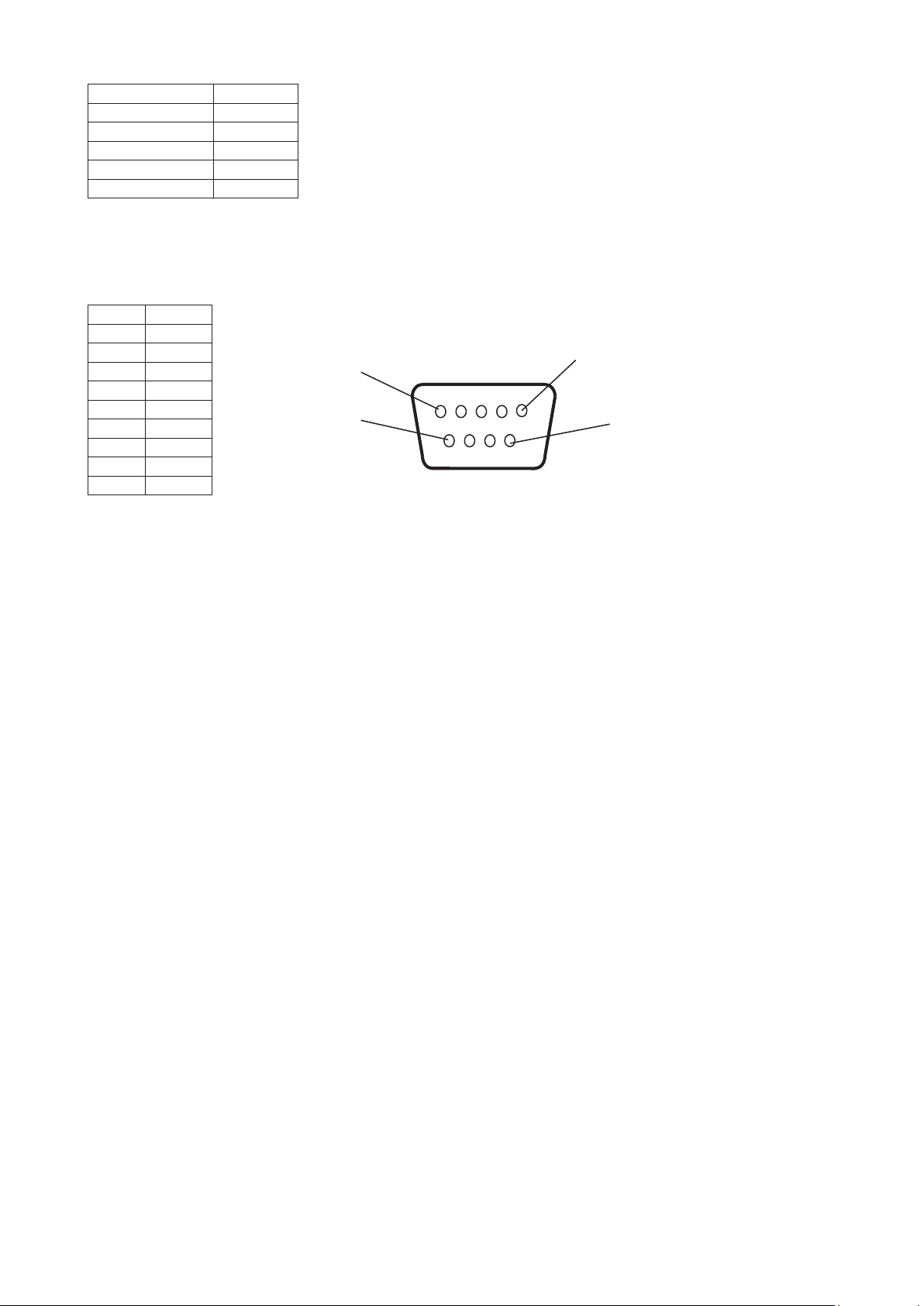
English-40
1) Interface
PROTOCOL RS-232C
BAUD RATE 9600 [bps]
DATA LENGTH 8 [bits]
PARITY NONE
STOP BIT 1 [bit]
FLOW CONTROL NONE
This LCD monitor uses RXD, TXD and GND lines for RS-232C control.
The reverse type cable (null modem cable) (not included) should be used for RS-232C control.
2) PIN ASSIGNMENT
RS-232C input/output
1
6
5
9
D-Sub 9-pin (Monitor side)
Pin No Name
1 NC
2 RXD
3 TXD
4 NC
5 GND
6 NC
7 NC
8 NC
9 NC
This LCD monitor uses RXD, TXD and GND lines for RS-232C control.
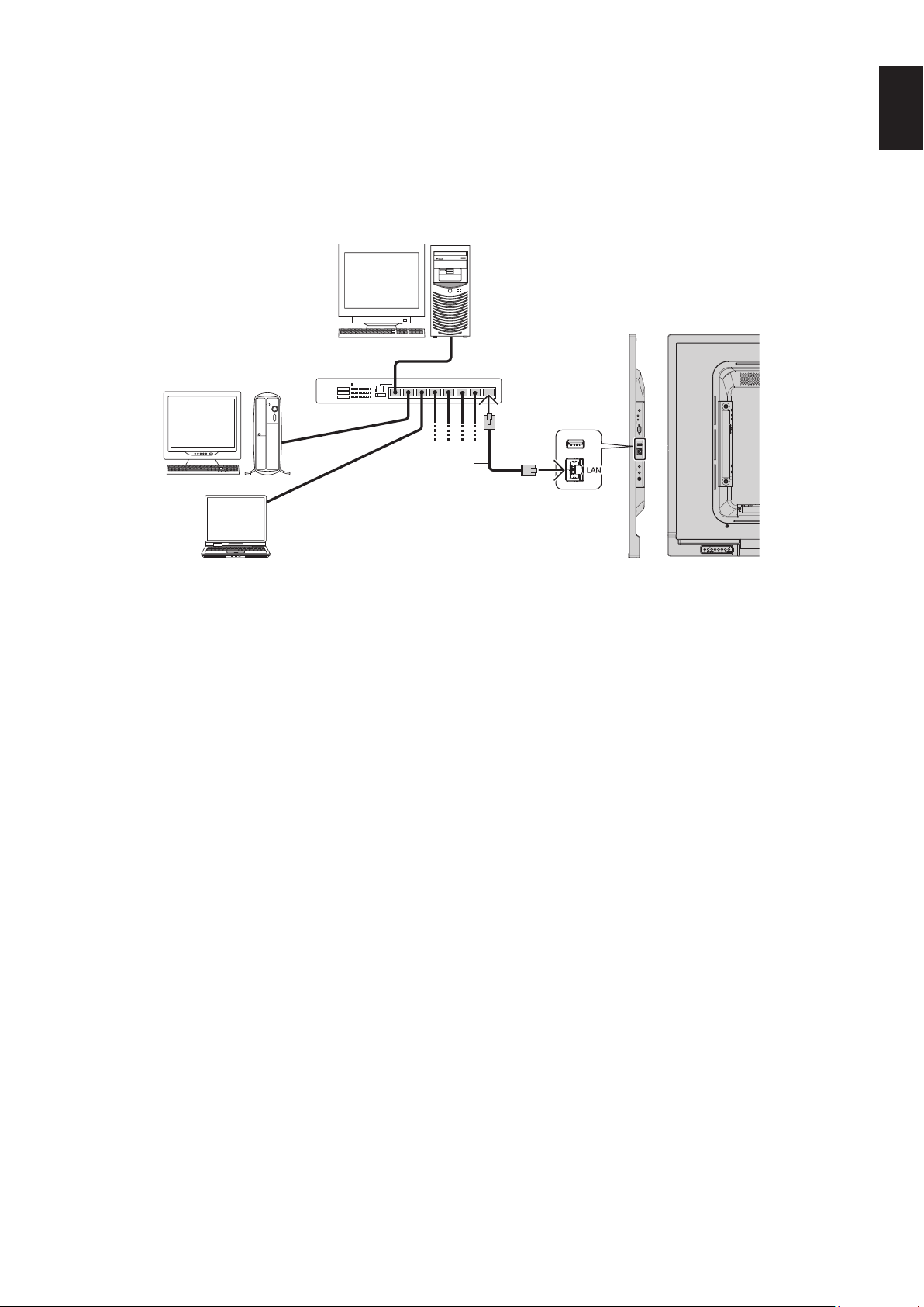
English-41
English
Connecting to a Network
Using a LAN cable allows you to specify the Network Settings and the Alert Mail Settings by using an HTTP server function.
To use a LAN connection you are required to assign an IP address.
Example of LAN connection:
Server
Hub
NOTE: Use a category 5 or higher LAN cable.
LAN cable
(not supplied)
Network Setting by Using an HTTP Browser
Overview
Connecting the monitor to a network allows for monitor control from a computer via the network.
The IP address and subnet mask of the monitor can be set on the Network Setting screen of the web browser by using an HTTP
server.Pleasebesuretouse“MicrosoftInternetExplorer10”orahigherversionforthewebbrowser.
(This device uses “JavaScript” and “Cookies” and the browser should be set to accept these functions. The setting method will
vary depending on the version of the browser. Please refer to the help files and the other information provided in your software.)
Access is gained to the HTTP server function by starting the Web browser on the computer via the network connected to the
monitor and entering the following URL as described below:
Network Setting
http://<theMonitor’sIPaddress>/index.html
HINT: The default IP address is assigned automatically to the monitor.
Theexclusiveapplicationcanbedownloadedfromourwebsite.
NOTE: If the MONITOR NETWORK SETTINGS screen does not appear in the web browser, press the Ctrl+F5 keys to
refresh your web browser (or clear the cache).
If the monitor appears to be slow in response to commands or clicks on buttons in the browser, or the general speed
of operation is unacceptable, this may be due to network traffic or the settings on your network. Should this happen,
consult your network administrator.
The monitor may not respond if the buttons shown on the browser are repeatedly pressed in rapid intervals. Should
this happen, wait a moment and repeat. If you still can’t get a response, turn the monitor off and then back on.
To control a monitor please use the control command. See “Control command diagram” (page 47).
Controlling the LCD monitor via LAN Control

English-42
Preparation Before Use
Connect the monitor to the network, using a commercially available LAN cable, before attempting to use browser operations.
Operationwithabrowserthatusesaproxyservermaynotbepossibledependingonthetypeofproxyserverandthesetting
method.Althoughthetypeofproxyserverwillbeafactor,itispossiblethatitemsthathavebeensetwillnotbeshown,
dependingontheeffectivenessofthecache,andthecontentssetfromthebrowsermaynotbereectedinoperation.
Itisrecommendedthataproxyserveris not used unless the network environment requires it.
Handling of the Address for Operation via a Browser
A host name can be used in the following cases (corresponding to the IP address of the monitor):
The host name must be registered in the domain name server (DNS) by the network administrator. You can then access the
network settings of the monitor via this registered host name by using a compatible browser.
If the host name has been configured in the “HOSTS” file of the computer being used, you can then access the network settings
of the monitor via this host name by using a compatible browser.
Example1: Whenthehostnameofthemonitorhasbeensetto“pd.nec.co.jp”,accessisgainedtothenetworksettingby
specifying
http://pd.nec.co.jp/index.html for the address or the entry column of the URL.
Example2: WhentheIPaddressofthemonitoris“192.168.73.1”,accessisgainedtothemailalertsettingsbyspecifying
http://192.168.73.1/index.html for the address or the entry column of the URL.
Operation
Access the following address to show HOME.
http://<theMonitor’sIPaddress>/index.html
Click each link on the left column below HOME.
REMOTE CONTROL
Enable an operation to control the monitor equivalent to the keys on the remote control.
OSD menu
Enable the operation to set the following OSD menu:
INPUT, PICTURE, AUDIO, SCHEDULE, MULTI INPUT, OSD, MULTI DISPLAY, DISPLAY PROTECTION, CONTROL, SYSTEM.
NOTE: Function of buttons which are shown on setting pages.
[APPLY]: Save your settings.
[CANCEL]: Return to the previous settings. NOTE: CANCEL is disabled after clicking APPLY.
[RELOAD]: Reload the settings.
[RESET]: Resets to the initial setting.
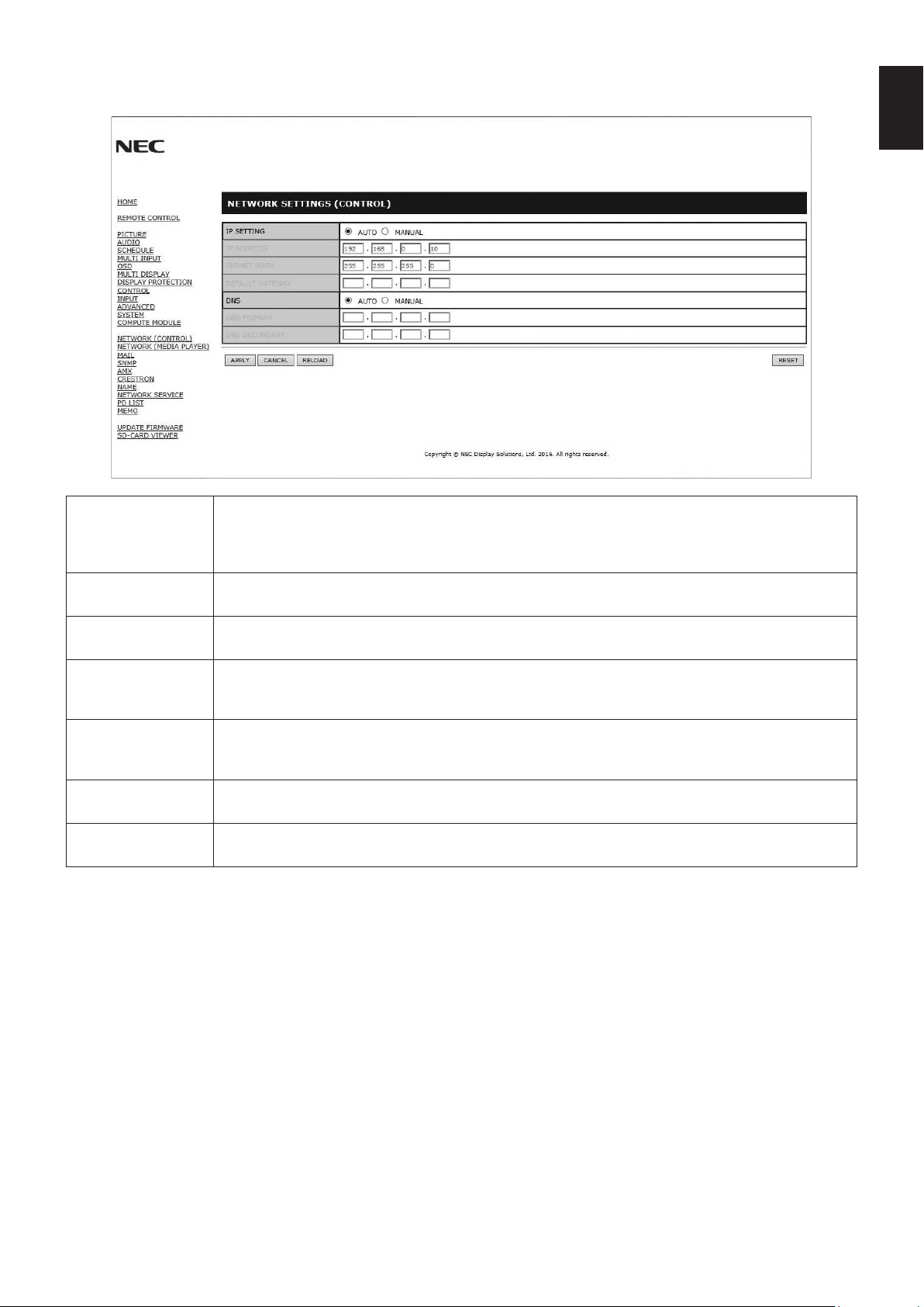
English-43
English
Network Setting
Click on “NETWORK” on the left column below HOME.
IP SETTING Select an option for setting the IP ADDRESS.
AUTO: Automatically assign an IP address.
MANUAL: Manually set an IP address for the monitor connected to the network.
NOTE: Consult your network administrator if you have any trouble.
IP ADDRESS Set your IP address for the monitor connected to the network when [MANUAL] is selected for
[IP SETTING].
SUBNET MASK Set your subnet mask data for the monitor connected to the network when [MANUAL] is selected for
[IP SETTING].
DEFAULT GATEWAY Set your default gateway for the monitor connected to the network when [MANUAL] is selected for
[IP SETTING].
NOTE: Set as [0.0.0.0] to delete the setting.
DNS Set for IP ADDRESS setting of DNS server.
AUTO: The DNS server connected to the monitor will automatically assign its IP address.
MANUAL: Manually enter the IP address of the DNS server that is connected with the monitor.
PRIMARY DNS Enter the primary DNS server settings of the network connected with the monitor.
NOTE: Enter [0.0.0.0] to delete the setting.
SECONDARY DNS Enter the secondary DNS server settings of the network connected with the monitor.
NOTE: Enter [0.0.0.0] to delete the setting.
NOTE: The following settings will be set back to the factory settings when IP ADDRESS RESET is selected at CONTROL of
the OSD:
[IP SETTING]: AUTO, [IP ADDRESS]: 192.168.0.10, [SUBNET MASK]: 255.255.255.0, [DNS]: AUTO [DEFAULT
GATEWAY], [PRIMARY DNS] and [SECONDARY DNS] are blank.
English-44
Mail Setting
Click on “MAIL” on the left column below HOME.
This option notifies your computer about an error message via e-mail when using wired LAN. An error message will be sent
when an error occurs in the monitor.
ALERT MAIL Selecting [ENABLE] will turn on the Alert Mail feature.
Selecting [DISABLE] will turn off the Alert Mail feature.
STATUS MESSAGE Selecting [ENABLE] will turn on the STATUS MESSAGE feature.
Selecting [DISABLE] will turn off the STATUS MESSAGE feature.
SENDER’S ADDRESS Type in the sender’s address. Up to 60 alphanumeric and symbols characters can be used.
SMTP SERVER Type in the SMTP server name to be connected with the monitor.
Up to 60 alphanumeric characters can be used.
RECIPIENT’S
ADDRESS 1 TO 3
Type in your recipient’s address. Up to 60 alphanumeric and symbols characters can be used.
AUTHENTICATION
METHOD
This selects the authentication method of the email transmission.
POP3 SERVER This specifies the address of the POP3 server that is used in the authentication of the email.
USER NAME This sets the user name for logging into the authentication server when authentication is required
for the email transmission. Up to 60 alphanumeric characters can be used.
PASSWORD This sets the password for logging into the authentication server when authentication is required for
the email transmission. Up to 60 alphanumeric characters can be used.
TEST MAIL Click this button to send a test email to check if your settings are correct.
NOTE: •Ifyouexecuteatest,youmaynotreceiveanAlertemail.
Should this happen, check whether the network settings are correct.
•Ifyouenteredanincorrectaddressinatest,youmaynotreceiveanAlertemail.
Should this happen, check that the Recipient’s Address is correct.
HINT: For the controlcommanddiagram,pleaseseethele“External_Control.pdf”ontheCD-ROMsupplied with this
monitor.
Alert error message list
Error number
* ErrorCode
Alert mail Message Explanation Measure
70h ~ 7Fh
The monitor’s power supply is not
functioning normally.
Standby power abnormal Please contact your supplier.
90h ~ 9Fh
The monitor’s backlight unit is not
functioning normally.
Backlight abnormal Please contact your supplier.
A0h ~ AFh The monitor is overheated. Temperature abnormal Please contact your supplier.
A2h
A Sensor reached the temperature limit
which was specified in the OSD.
Please contact your supplier.
B0h ~ BFh
The monitor does not receive an input
signal.
No signal Please check “No picture” in
“Troubleshooting”.
D1h
The battery for clocks is empty. The battery is empty. Please connect the monitor to the
power then recharge the battery.
Please set (DATE & TIME) in OSD.
E0h ~ EFh A system error occurred in the monitor. System error. Please contact your supplier.
English-45
English
SNMP Settings
Click on “SNMP” on the left column below HOME.
The SNMP protocol is used to get status information and to control a monitor directly via the network.
Version:
SNMPv1Authenticatedplaintextbycommunityname,doesnotreturnaconrmationmessageofthetrap.
SNMPv2cAuthenticatedplaintextbycommunityname,returnsaconrmationmessageofthetrap.
Community name:
The default setting of community name is “public”. It is read only. You can set community names for up to 3 settings.
Trap:
Sending error message to a specified address when an error occurs in the monitor.
CheckBoxExplanationError code
Temperature Temperature abnormal 0xA0,0xA1,0xA2
Power Power abnormal 0x70,0x71,0x72,0x78
Inverter/Backlight Inverter or backlight abnormal 0x90,0x91
No Signal No signal 0xB0
System Error System error 0xE0
AMX Settings
Click on “AMX” on the left column below HOME.
AMX BEACON To turn on or off for the detection from AMX Device Discovery when connecting to a network
supportedbyanAMX’sNetLinxcontrolsystem.
HINT:
When using a device that supports AMX Device Discovery, all AMX NetLinx control systems will
recognize the device and download the appropriate Device Discovery Module from an AMX server.
Selecting [ENABLE] AMX Device Discovery will detect the device.
Selecting [DISABLE] AMX Device Discovery will not detect the device.
CRESTRON Settings
Click on “CRESTRON” on the left column below HOME.
CRESTRON ROOMVIEW compatibility
The monitor supports CRESTRON ROOMVIEW, allowing multiple devices connected in the network to be managed and
controlled from a computer or a controller.
For further information visit http://www.crestron.com
ROOMVIEW ROOMVIEW for managing from the computer.
ON: Enables ROOMVIEW.
OFF: Disables ROOMVIEW.
CRESTRON
CONTROL
CRESTRON CONTROL for managing from the controller.
ON: Enables CRESTRON CONTROL.
OFF: Disables CRESTRON CONTROL.
CONTROLLER IP
ADDRESS
Sets the IP address of the CRESTRON SERVER.
IP ID Sets your CRESTRON SERVER IP ID.
HINT: The CRESTRON settings are required only for use with CRESTRON ROOMVIEW.
For further information visit http://www.crestron.com
English-46
Name Settings
Click on “NAME” on the left column below HOME.
MONITOR NAME Definesamonitorname.Thenamemustbemax.16characterslong.Thedefaultisthemodelname.
HOST NAME
(CONTROL)
Type in the hostname of the monitor which is connected to the network.
Up to 15 alphanumeric characters can be used.
HOST NAME (MP) Type in the hostname of the network to be used in the Media Player connected to the monitor.
Up to 15 alphanumeric characters can be used.
DOMAIN NAME Type in the domain name of the network which is connected with the monitor.
Up to 60 alphanumeric characters can be used.
Network Password Settings
Click on “NETWORK PASSWORD” on the left column below HOME.
PJLink CLASS Set a class for PJLink*.
NOTE: PJLink is a network interface standard that JBMIA established.
http://pjlink.jbmia.or.jp/index.html
This monitor is available for class1 and class2 command.
NOTIFY FUNCTION
ENABLE
Enable or disable a notification of the monitor network condition. This function is only for class2.
NOTIFY ADDRESS Set an IP ADDRESS to which the monitor network status will be sent. This function is only for class2.
PJLink PASSWORD Set a password for PJLink*. The password must be max.32characterslong. Do not forget your
password. If you forget your password, consult your supplier.
HTTP PASSWORD Set a password for the HTTP server. The password must be max.10characterslong.
HTTP PASSWORD
ENABLE
An HTTP PASSWORD is required when logging into the HTTP server.
Set the monitor name as the USER NAME when entering the password.
*What is PJLink?
PJLinkisastandardizationofprotocolusedforcontrollingdevicesofdifferentmanufacturers.Thisstandardprotocolwas
established by Japan Business Machine and Information System Industries Association (JBMIA) in 2005.
The device supports all commands of PJLink.
MEMO Settings
Click on “MEMO” on the left column below HOME.
Set a title and message.
TITLE The title must be max.24characterslong.
MESSAGE A message must be max.240characterslong.
MEMO PASSWORD The default is “0000”.
MEMO PASSWORD
ENABLE
A MEMO PASSWORD is required when selecting MEMO PASSWORD ENABLE.
SD-CARD VIEWER setting
Click “SD-CARD VIEWER” on the left side of HOME.
Please refer to Using SHARED SD card SETTINGS (See page 23).
External Control
Connecting external device
There are two ways to connect an externaldevicetothemonitor.
•RS-232C terminal.
ConnectinganexternaldevicetotheRS-232Cterminalofthemonitorwithan RS-232C cable.
•LAN port.
ConnectinganexternaldevicetotheLANportofthemonitorwithaLANcable.
For further information regarding the type of LAN cable to use, please consult your network administrator.
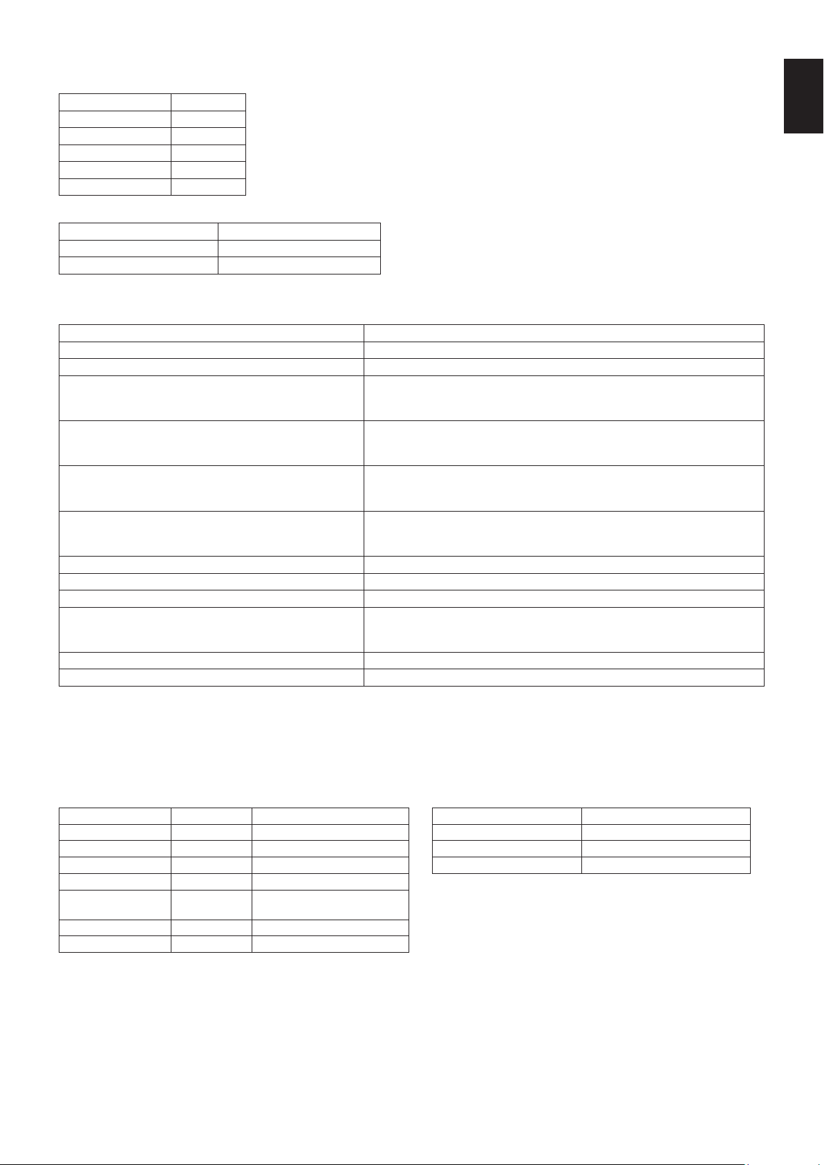
English-47
English
Connecting interface
RS-232C Interface
PROTOCOL RS-232C
BAUD RATE 9600 [bps]
DATA LENGTH 8 [bits]
PARITY NONE
STOP BIT 1 [bit]
FLOW CONTROL NONE
LAN interface
PROTOCOL TCP
PORT NUMBER 7142
COMMUNICATION SPEED AUTO setting (10/100Mbps)
Control command diagram
Forothercommands,pleasesee“External_Control.pdf”leontheCD-ROMsupplied with the monitor.
Function (Monitor ID = 1) Code Data
Power ON 01 30 41 30 41 30 43 02 43 32 30 33 44 36 30 30 30 31 03 73 0d
Power OFF 01 30 41 30 41 30 43 02 43 32 30 33 44 36 30 30 30 34 03 76 0d
Input Source Select DisplayPort
01 30 41 30 45 30 41 02 30 30 36 30 30 30 30 46 03 04 0d
or
01 30 41 30 45 30 41 02 31 31 30 36 30 30 30 46 03 04 0d
Input Source Select HDMI1
01 30 41 30 45 30 41 02 30 30 36 30 30 30 31 31 03 72 0d
or
01 30 41 30 45 30 41 02 31 31 30 36 30 30 31 31 03 72 0d
Input Source Select HDMI2
01 30 41 30 45 30 41 02 30 30 36 30 30 30 31 32 03 71 0d
or
01 30 41 30 45 30 41 02 31 31 30 36 30 30 31 32 03 71 0d
Input Source Select HDMI3
01 30 41 30 45 30 41 02 30 30 36 30 30 30 38 32 03 78 0d
or
01 30 41 30 45 30 41 02 31 31 30 36 30 30 38 32 03 78 0d
Input Source Select VGA (RGB) 01 30 41 30 45 30 41 02 30 30 36 30 30 30 30 31 03 73 0d
Input Source Select VGA (YPbPr) 01 30 41 30 45 30 41 02 30 30 36 30 30 30 30 43 03 01 0d
Input Source Select VIDEO 01 30 41 30 45 30 41 02 30 30 36 30 30 30 30 35 03 77 0d
Input Source Select MP
01 30 41 30 45 30 41 02 30 30 36 30 30 30 38 37 03 7D 0d
or
01 30 41 30 45 30 41 02 31 31 30 36 30 30 38 37 03 7D 0d
Sound Mute ON 01 30 41 30 45 30 41 02 30 30 38 44 30 30 30 31 03 09 0d
Sound Mute OFF 01 30 41 30 45 30 41 02 30 30 38 44 30 30 30 32 03 0a 0d
ASCII Control command
This monitor supports control command, which is listed in the “External_Control.pdf” file on the CD-ROM supplied with the
monitor, but also supports common ASCII control command, which is used for controlling the NEC monitor or projector from a
connected PC. For further information please visit our website.
Parameter
Input command Status command
Input signal name Response Parameter Response Error status
DisplayPort DisplayPort DisplayPort or DisplayPort1 error:temp Temperature abnormal
HDMI1 hdmi1 hdmi1 or hdmi error:light Inverter or backlight abnormal
HDMI2 hdmi2 hdmi2 error:system System error
HDMI3 hdmi3 hdmi3
VGA vga vga, vga1, computer,
computer1, rgb or rgb1
VIDEO video video or video1
MP mp mp
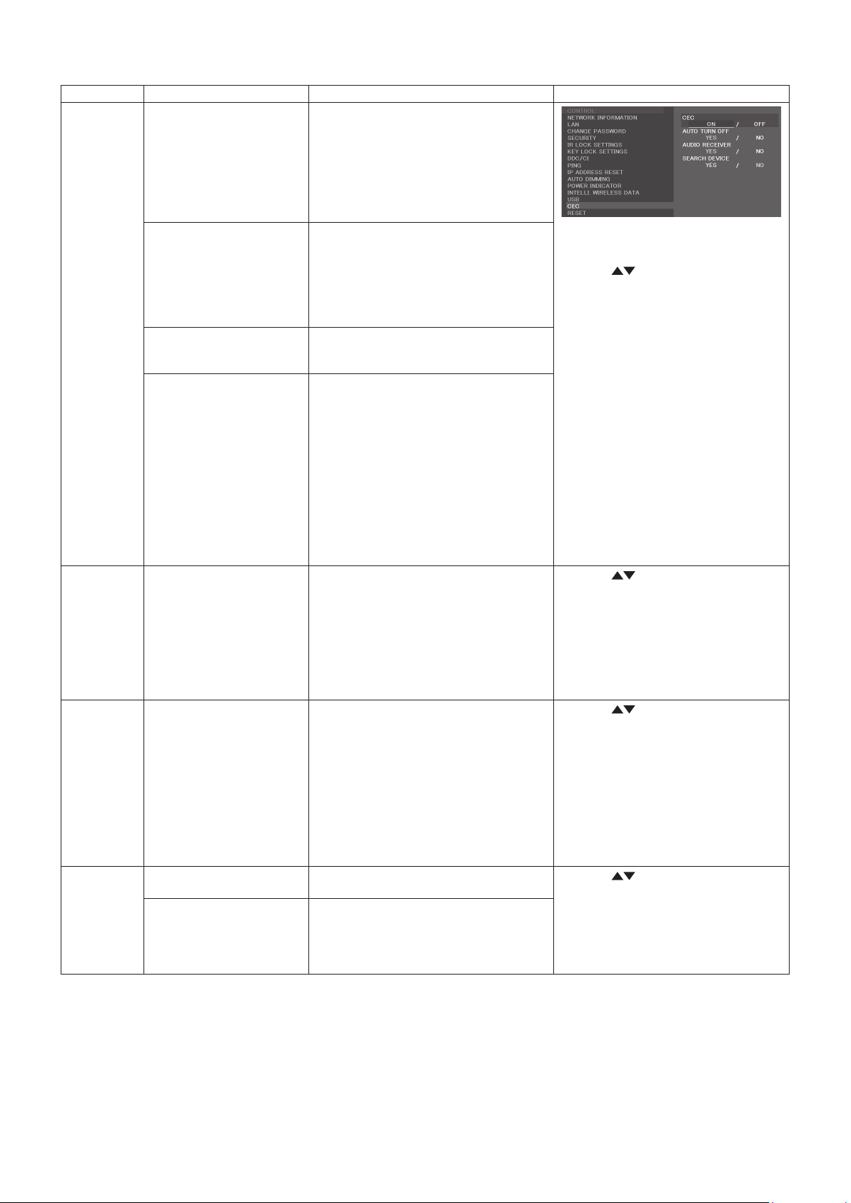
English-48
Supporting HDMI CEC command
OSD menu
HDMI CEC command name Explanation
Setting
CEC
(Consumer
Electronics
Control)
One Touch Play If HDMI CEC supporting devices are
turned on, the monitor connected to the
devices by HDMI cable is also turned on
automatically. After that, the input switches
to HDMI from an input, which you selected.
If the monitor is turned on when HDMI
CEC devices are turned on, it changes the
input from the original one to HDMI.
To set CEC menus please follow the
steps below.
By using buttons select
CONTROL > CEC then press
SET/POINT ZOOM button on the CEC.
By using + - buttons select ON then
press SET/POINT ZOOM button on
the ON.
Remote Control Pass
Through
The monitor’s wireless remote control
button operation is functioning to HDMI
CEC supporting devices.
Forexample,ifturning on the monitor by
wireless remote control and pressing the
play button, HDMI CEC supporting devices
will also be turned on and play.
Power Status Connected HDMI CEC supporting devices
obtains the monitor’s power status, such as
the monitor is in standby mode or on.
System Information This function obtains the information of a
connected HDMI CEC supported device
(CEC version, Physical Address). In
addition, this function copes with “Change
Language function”.
If the language for the monitor is changed,
the language for a connected HDMI CEC
supported device is changed to the same
language, which is selected for the monitor.
For the “Change Language function”, it is
necessary that the connected HDMI CEC
supported device be able to cope with
multi-language.
AUTO
TURN OFF
System Standby If the monitor is set to standby using the
wireless remote control supplied with the
monitor, HDMI CEC supported devices
also go into standby at the same time.
If the monitor goes into standby while an
HDMI CEC supported device is recording,
the device is kept on. Please refer to the
user’s manual supplied with the HDMI CEC
supported device for further information.
By using
buttons select
AUTO TURN OFF then press
SET/POINT ZOOM.
By using + - buttons select YES
then press SET/POINT ZOOM button
on the YES.
AUDIO
RECEIVER
System Audio Control The function sends digital audio signal
through the HDMI cable. Please set an
HDMI CEC audio amplifier between the
monitor and an HDMI CEC supported
device with an HDMI cable.
The Volume button on the wireless
remote control supplied with the monitor
is also controlling the volume of the
connected HDMI CEC audio amplifier.
While this function is active, the internal
speaker is set to MUTE automatically.
By using
buttons select
AUDIO RECIEVER then press
SET/POINT ZOOM.
By using + - buttons select YES
then press SET/POINT ZOOM button on
the YES.
SEARCH
DEVICE
Device OSD Name Transfer This function obtains the connected HDMI
CEC supported device’s name.
By using
buttons select SEARCH
DEVICE then press SET/POINT ZOOM.
By using + - buttons select YES then
press SET/POINT ZOOM button on
the YES.
Routing Control By selecting a device name, the HDMI
CEC supported device input switches to
the input you selected. After selecting the
device, wireless remote control operation is
functioning for the selected device.
This CEC function supports Feature Abort. We recommend that connecting this monitor to a device supporting HDMI CEC.
Please refer to Connections (See page 14) for HDMI CEC devices connection.

English-49
English
Using the “SET/POINT ZOOM” button on the remote control enlarges part of the screen image.
PresstheCH+/-buttontozoominorout.Theimagecanbeexpandedupto10times.
1 Press the [SET/POINT ZOOM] button on the remote control. The icon looks like a magnifier.
2 Move the magnifier icon with the [ ] [ ] [+] [-] buttons.
3Pressthe[CH+]tozoomin.Press[CH-]tozoomout.
4 Press the [SET/POINT ZOOM] to let the icon disappear.
5Pressthe[EXIT]toreturntothenormalimagesize.
6 Press the [MENU] to open the OSD menu.
NOTE: •When using this function the image may look distorted.
•Thisfunctionis not available when set to SCREEN SAVER, CLOSED CAPTION and TILE MATRIX.
•WhenZOOM is selected in ASPECT, the image will change to FULL. Then start with POINT ZOOM.
AfterexitingPOINTZOOM,ASPECTwillreturntothepreviousASPECTsettings.WhenASPECTischanged
during the POINT ZOOM operation, ZOOM will be set to FULL image.
•Themagniericondoesnotmovetoanoimagearea.
•POINT ZOOM returnstothenormalimagesize after changing the input signal or when the monitor is powered off.
•POINTZOOMwill become inactive when changing the ASPECT setting during the POINT ZOOM operation.
•When the POINT ZOOM is active, the STILL function is not available.
POINT ZOOM

English-50
Natural Color Matrix:CombinesSix-axiscolorcontrolandthesRGBstandard.Six-axiscolorcontrolpermitscoloradjustments
viasixaxes(R,G,B,C,MandY)ratherthanthroughthethreeaxes(R,GandB)previouslyavailable.ThesRGBstandard
provides the monitor with a uniform color profile. This ensuresthatthecolorsdisplayedonthemonitorareexactlythesameas
on the color printout (with sRGB supporting operating system and sRGB printer). This allows you to adjust the colors on your
screen and customise the color accuracy of your monitor to a variety of standards.
sRGB Color Control: A color management standard which allows for color matching on computer monitors and other
peripherals. The sRGB standard, which is based on a calibrated color space, allows for optimal color representation and
backward compatibility with other common color standards.
OSD (On-Screen-Display) Controls: Provides access for quick and easy adjustment to all elements of the screen image via
simple to use on-screen menus.
Plug and Play: The Microsoft
®
solution with the Windows
®
operating system facilitates setup and installation by allowing the
monitor to send its capabilities(suchasscreensizeandresolutionssupported)directlytothecomputer,automaticallyoptimizing
display performance.
IPM (Intelligent Power Manager) System: Provides innovative power-saving methods that allow the monitor to shift to a lower-
power mode when on but not in use, reducing emissions and lowering the cost of operating the monitor by reducing its power
consumption.
FullScan Capability: Allowsuseoftheentirescreenareainmostresolutions,signicantlyexpandingtheimagesize.
VESA Standard (FDMIv1) Mounting Interface: Mounts the monitor to any VESA standard (FDMIv1) third party mounting arm
or bracket. NEC recommends using mounting equipment which complies with TÜV-GS (Germany) and/or UL1678 standard
(North America).
ZOOM: Expands/reducestheimagesizeinhorizontalandverticaldirection.
Self-diagnosis: If an internal error should occur, a failure state will be indicated.
HDCP (High-bandwidth Digital Content Protection): HDCP is a system for preventing illegal copying of video data sent over
a digital signal. If you are unable to view material via the digital input, this does not necessarily mean that the monitor is not
functioning properly. With the implementation of HDCP, there may be cases in which certain content is protected by HDCP and
might not be displayed due to the decision/intention of the HDCP community (Digital Content Protection, LLC).
TILE MATRIX, TILE COMP: Showsoneimageovermultiplescreenswithaccuracywhilecompensatingforbezelwidth.
Features

English-51
English
No picture
•Thesignalcableshouldbecompletelyconnectedtothe
display card/computer.
•Thedisplaycardshouldbecompletelyseatedinitsslot.
•CheckthemainPowerSwitch,itshouldbeintheON
position.
•Power Switches for the monitor and computer should be
in the ON position.
•Makesurethatasupportedresolutionhasbeenselected
on the display card or system being used. If in doubt,
please refer to the user’s manual of the display card or
system to change the resolution.
•Checkthemonitorandyourdisplaycardwithrespectto
compatibility and recommended signal timings.
•Checkthesignalcableconnectorforbentorpushed-in
pins.
•Themonitorautomaticallygoesintostandby at the preset
time period after the video signal was lost. Press the
power on button on the remote control or press the power
button on the monitor.
•If you unplug the signal cable when starting the computer,
images may not be displayed. Turn off the monitor and
the computer and then connect the signal cable and turn
on the computer and the monitor.
Power Button does not respond
•UnplugthepowercordofthemonitorfromtheACoutlet
to turn off and reset the monitor.
•CheckthemainPowerSwitchonthemonitor.
Image persistence
•PleasebeawarethatLCDTechnologymayexperience
a phenomenon known as Image Persistence. Image
Persistence occurs when a residual or “ghost” image of
a previous image remains visible on the screen. Unlike
CRT monitors, the image persistence of LCD monitors is
not permanent, but single still image being displayed for a
long period of time should be avoided. To alleviate image
persistence, put the monitor into standby via remote
control or turn the monitor’s main power off for as long
asthepreviousimagewasdisplayed.Forexample,ifan
image was on the monitor for one hour and a residual
image remains, the monitor should be in standby or main
power off for one hour to erase the image.
NOTE: As with all personal display devices, NEC
DISPLAY SOLUTIONS recommends displaying
moving images, using a moving screen saver, or
changing still images at regular intervals whenever
the screen is idle, or turning it into standby or main
power off of the monitor when not in use.
The image is blinking
•If you use a signal repeater or distributor or a long
cable, this may cause image roughness or blink for a
moment. In this case please connect the cable to the
monitor directly without using a repeater or a distributor,
or replace the cable with a higher quality cable. Using
atwistedpairextendermaycauseimageroughness
depending on the environment where the monitor is in or
the cable you are using. For further information please
ask your supplier.
The image is unstable, unfocused or swimming is
apparent
•Thesignalcableshouldbecompletelyattachedtothe
computer.
•UsetheOSDImageAdjustcontrolstofocusand
adjust the display by increasing or decreasing the fine
adjustment.
When the display mode is changed, the OSD Image
Adjust settings may need to be re-adjusted.
•Checkthemonitorandyourdisplaycardwithrespectto
compatibility and recommended signal timings.
•Iftextlooksgarbled,changethevideomodetonon-
interlacedandusea60Hzrefreshrate.
•Theimagemaybedistortedwhenturningthepoweronor
changing the settings.
The image of component signal is greenish
•ChecktoseeiftheVGA (YPbPr) input connector is
selected.
LED on the monitor is not lit (no blue or red color can be
seen)
•ThemainPowerSwitchshouldbeintheONpositionand
the power cord should be connected.
•Makecertainthecomputerisnotinapower-savingmode
(touch the keyboard or move the mouse).
•Check in the OSD that the power indicator option is set to
ON.
LED colors, except for blue, are blinking or glowing
•A certain failure might have occurred, please contact your
supplier.
•If the monitor is powered off by the internal temperature
being higher than the normal operating temperature,
the LED will blink green or amber or redforsixtimes.
Power on the monitor again after confirming the internal
temperature has been reduced to normal operation
temperature.
•The monitor could be in standby.
Press the power on button on the remote control or press
the power button on the monitor.
The image is not properly reproduced
•UsetheOSDImageAdjustcontrolstoincreaseor
decrease the coarse adjustment.
•Makesurethatasupportedresolutionhasbeenselected
on the display card or system being used.
If in doubt, please refer to the user’s manual of the display
card or system to change the resolution.
Selected resolution is not displayed properly
•UseOSDDisplayModetoenterInformationmenuand
confirm that the appropriate resolution has been selected.
Troubleshooting

English-52
Eitherlightverticalorhorizontalstripesmayappear,dependingonthespecicimagepattern.Thisisnotaproductfaultordegradation.
No Sound
•Checktoseeiftheaudiocableisproperlyconnected.
•ChecktoseeifMUTE is activated. Use the remote control
to enable or disable the Mute function.
•ChecktoseeifVOLUME is set to a minimum.
•Checktoseeifthecomputersupportsanaudiosignal
through DisplayPort.
If unsure, contact your supplier.
•WhenLINEOUTisnotfunctioning,checktoseeif
SURROUND is ON.
•If HDMI CEC audio device is not connected, please set
“AUDIO RECEIVER” to OFF.
The Remote Control is not functioning
•Check the batteries status of the Remote Control.
•Checkifthebatteriesareinsertedcorrectly.
•CheckiftheRemoteControlispointingatthe remote
control sensor of the monitor.
•Check the status of IR LOCK SETTINGS.
•Theremotecontrolsystemmaynotfunctionwhendirect
sunlight or strong illumination strikes the remote control
sensor of the monitor, or when there is an object in the
path.
The SCHEDULE/OFF TIMER function is not working
properly
•The“SCHEDULE”functionwillbedisabledwhenthe
“OFF TIMER” is set.
•Ifthe“OFFTIMER”functionisenabledandthepowerto
the LCD monitor is turned off when the power supply is
interruptedunexpectedly,thenthe“OFFTIMER”willbe
reset.
Interference in TV
•Checkcomponentsforshielding,moveawayfrom
monitor if necessary.
RS-232C or LAN control is not available
•CheckRS-232C (reverse type) or the LAN cable.
A category 5 or higher LAN cable is required for
connection.
The monitor goes into standby automatically
•Please check “OFF TIMER” setting.
•Set the “CEC” function to OFF.
Media Player function does not recognize the USB
storage device
•Please check a USB storage device is connected to the
USB (2A).
The USB Hub does not operate
•Check to make sure the USB cord is properly connected.
Refer to your USB device User’s Manual.
• Checktheformatifthisdevicecannotrecognizethe
connected USB memory.
MicroSD card does not work
•Check to make sure the microSD card is properly
connected.
•Check the microSD memory card format.

English-53
English
Specifications - C431
Product Specifications
LCD Module
PixelPitch:
Resolution:
Color:
Brightness:
Contrast Ratio:
Viewing Angle:
43"/107.95 cm diagonal
0.49 mm
1920x1080
Over 1073 million colors (depending on display card used)
400 cd/m
2
(Max.)@25°C
4000:1
89°(typ)@CR>10
Frequency Horizontal:
Vertical:
15.625/15.734kHz,31.5kHz-91.1kHz
50.0-85.0Hz(AnalogInput)
24.0-85.0Hz(DigitalInput)
PixelClockAnalog:13.5MHz,25.0MHz-165.0MHz
Digital:25.0MHz-165.0MHz
ViewableSize940.90x529.25 mm
Input Signal
DisplayPort DisplayPort Connector Digital RGB DisplayPort V1.1a (HDCP1.3)
SVGA60, XGA60, WXGA60, SXGA60, UXGA60, WUXGA60*
1
,1920x1080(60Hz),1080p,
1080i,720p@50Hz/60Hz
VGA
(RGB)*
2
Mini D-Sub 15-pin Analog RGB 0.7 Vp-p/75 ohm
VGA60, SVGA60, XGA60, WXGA60, SXGA60, UXGA60*
1
, WUXGA60*
1
,1920X1080(60Hz)
Sync Separate: TTL level (Pos./Neg.)
Composite sync on Green Video: 0.3 Vp-p Neg.
HDMI HDMI Connector Digital YUV
Digital RGB
HDMI (HDCP1.4)
SVGA60, XGA60, WXGA60, SXGA60, UXGA60, WUXGA60*
1
,1920x1080(60Hz),1080p,
1080i,720p@50Hz/60Hz
VGA
(YPbPr)*
2
Mini D-Sub 15-pin Component Y: 1.0 Vp-p/75ohm, Cb/Cr (Pb/Pr): 0.7 Vp-p/75 ohm
HDTV/DVD:1080p,1080i,720p@50Hz/60Hz,576p@50Hz,480p@60Hz,576i@50Hz,
480i@60Hz
VIDEO*
2
RCA port Composite 1.0 Vp-p/75 ohm
NTSC/PAL/SECAM/4.43NTSC/PAL60
AUDIO
AUDIO
Input
Stereo Mini Jack Analog Audio StereoL/R0.5Vrmsx2
HDMI Connector Digital Audio PCM32,44.1,48KHz(16/20/24bit)
DisplayPort Connector Digital Audio PCM32,44.1,48KHz(16/20/24bit)
AUDIO
Output
Stereo Mini Jack Analog Audio Stereo L/R 0.5 Vrms
Speaker Output Internal Speaker 10 W + 10 W (Stereo)
Control RS-232C In:
LAN:
Remote IN:
Remote OUT:
D-Sub 9-pin
RJ-45 10 BASE-T/100 BASE-TXx1
Stereo Mini Jack 3.5 mm Ø
Stereo Mini Jack 3.5 mm Ø
SD card Slot Port: microSD card. Up to 32GB microSDHC is supported.
USB Port USB (2A): Media Player/Firmware update/Power supply port 5V/2A(max.)
Power Supply 1.35-0.55A@100-240VAC,50/60Hz
Power Consumption Normal operation: Approx.50 W
Operational Environment Temperature:
Humidity:
Altitude:
0-40°C/32-104°F
20-80%(withoutcondensation)
0 - 3000 m (Brightness may decrease with altitude)
Storage Environment Temperature:
Humidity:
-20-60°C/-4-140°F
10-90%(withoutcondensation)/90%-3.5%x(Temp-40°C)regardingover40°C
Dimension*
3
970.7(W)x558.9(H)x45.0(D)mm/38.2(W)x22.0(H)x1.8 (D) inches
Weight 12.5 kg (27.6 lbs)
VESA compatible mounting interface 300mmx300mm(M6,4Holes)
Power Management VESA DPM
NOTE: Technical specifications are subject to change without notice.
*1: Compressed image.
*2: Common terminal.
*3: Measurements are of the monitor only and do not include removable parts that protrude.
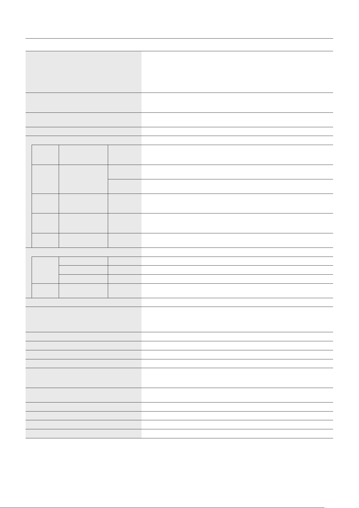
English-54
Specifications - C501
Product Specifications
LCD Module
PixelPitch:
Resolution:
Color:
Brightness:
Contrast Ratio:
Viewing Angle:
50"/125.73 cm diagonal
0.57 mm
1920x1080
Over 1073 million colors (depending on display card used)
400 cd/m
2
(Max.)@25°C
4000:1
89°(typ)@CR>10
Frequency Horizontal:
Vertical:
15.625/15.734kHz,31.5kHz-91.1kHz
50.0-85.0Hz(AnalogInput)
24.0-85.0Hz(DigitalInput)
PixelClockAnalog:13.5MHz,25.0MHz-165.0MHz
Digital:25.0MHz-165.0MHz
ViewableSize1095.84x616.41 mm
Input Signal
DisplayPort DisplayPort Connector Digital RGB DisplayPort V1.1a (HDCP1.3)
SVGA60, XGA60, WXGA60, SXGA60, UXGA60, WUXGA60*
1
,1920x1080(60Hz),1080p,
1080i,720p@50Hz/60Hz
VGA
(RGB)*
2
Mini D-Sub 15-pin Analog RGB 0.7 Vp-p/75 ohm
VGA60, SVGA60, XGA60, WXGA60, SXGA60, UXGA60*
1
, WUXGA60*
1
,1920X1080(60Hz)
Sync Separate: TTL level (Pos./Neg.)
Composite sync on Green Video: 0.3 Vp-p Neg.
HDMI HDMI Connector Digital YUV
Digital RGB
HDMI (HDCP1.4)
SVGA60, XGA60, WXGA60, SXGA60, UXGA60, WUXGA60*
1
,1920x1080(60Hz),1080p,
1080i,720p@50Hz/60Hz
VGA
(YPbPr)*
2
Mini D-Sub 15-pin Component Y: 1.0 Vp-p/75ohm, Cb/Cr (Pb/Pr): 0.7 Vp-p/75 ohm
HDTV/DVD:1080p,1080i,720p@50Hz/60Hz,576p@50Hz,480p@60Hz,576i@50Hz,
480i@60Hz
VIDEO*
2
RCA port Composite 1.0 Vp-p/75 ohm
NTSC/PAL/SECAM/4.43NTSC/PAL60
AUDIO
AUDIO
Input
Stereo Mini Jack Analog Audio StereoL/R0.5Vrmsx2
HDMI Connector Digital Audio PCM32,44.1,48KHz(16/20/24bit)
DisplayPort Connector Digital Audio PCM32,44.1,48KHz(16/20/24bit)
AUDIO
Output
Stereo Mini Jack Analog Audio Stereo L/R 0.5 Vrms
Speaker Output Internal Speaker 10 W + 10 W (Stereo)
Control RS-232C In:
LAN:
Remote IN:
Remote OUT:
D-Sub 9-pin
RJ-45 10 BASE-T/100 BASE-TXx1
Stereo Mini Jack 3.5 mm Ø
Stereo Mini Jack 3.5 mm Ø
SD card Slot Port: microSD card. Up to 32GB microSDHC is supported.
USB Port USB (2A): Media Player/Firmware update/Power supply port 5V/2A(max.)
Power Supply 1.50-0.60A@100-240VAC,50/60Hz
Power Consumption Normal operation: Approx.65 W
Operational Environment Temperature:
Humidity:
Altitude:
0-40°C/32-104°F
20-80%(withoutcondensation)
0 - 3000 m (Brightness may decrease with altitude)
Storage Environment Temperature:
Humidity:
-20-60°C/-4-140°F
10-90%(withoutcondensation)/90%-3.5%x(Temp-40°C)regardingover40°C
Dimension*
3
1124.7(W)x645.3(H)x45.0(D)mm/44.3(W)x25.4(H)x1.8 (D) inches
Weight 16.1 kg (35.5 lbs)
VESA compatible mounting interface 300mmx300mm(M6,4Holes)
Power Management VESA DPM
NOTE: Technical specifications are subject to change without notice.
*1: Compressed image.
*2: Common terminal.
*3: Measurements are of the monitor only and do not include removable parts that protrude.
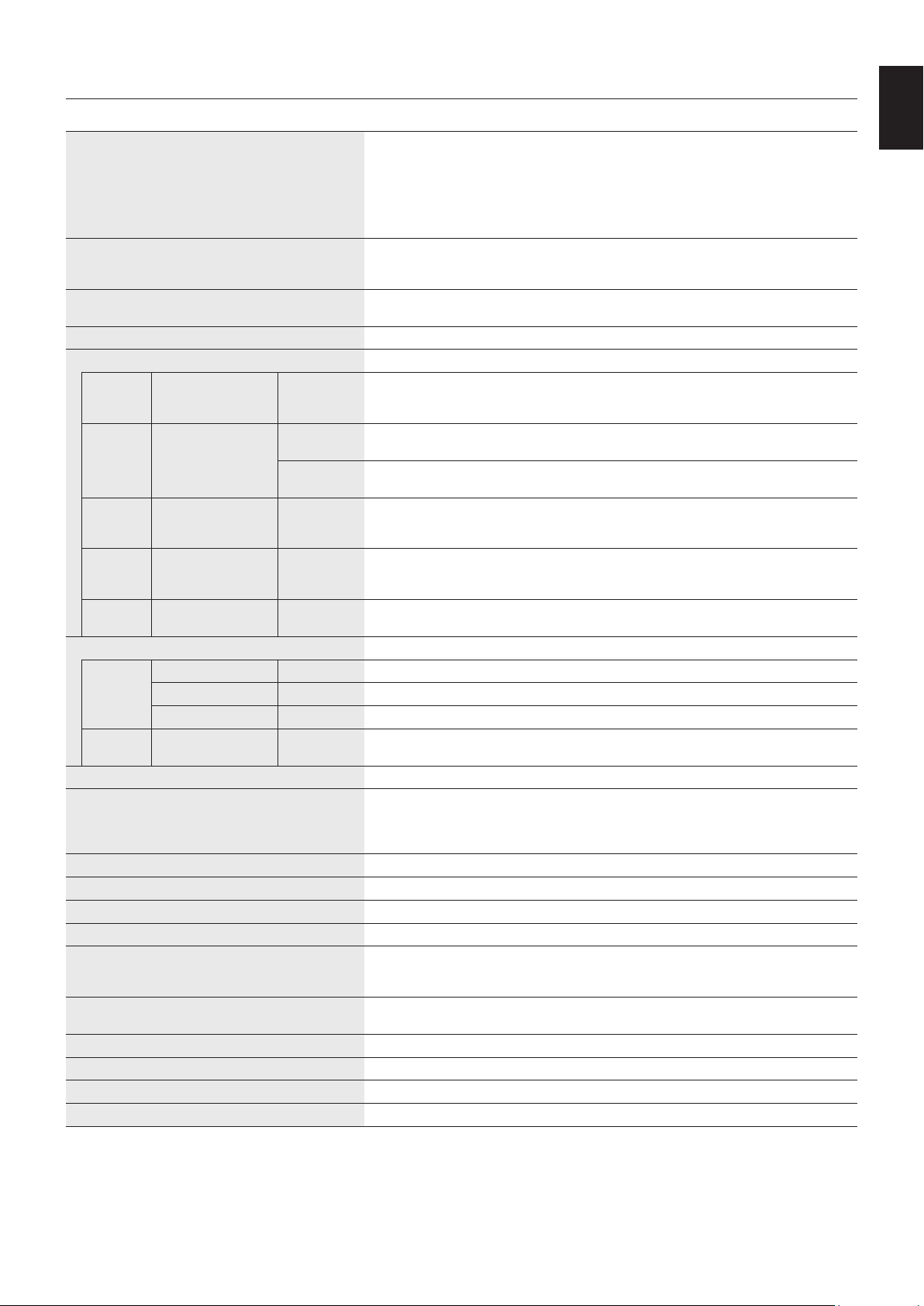
English-55
English
Specifications - C551
Product Specifications
LCD Module
PixelPitch:
Resolution:
Color:
Brightness:
Contrast Ratio:
Viewing Angle:
55"/138.78 cm diagonal
0.63 mm
1920x1080
Over 1073 million colors (depending on display card used)
400 cd/m
2
(Max.)@25°C
4000:1
89°(typ)@CR>10
Frequency Horizontal:
Vertical:
15.625/15.734kHz,31.5kHz-91.1kHz
50.0-85.0Hz(AnalogInput)
24.0-85.0Hz(DigitalInput)
PixelClockAnalog:13.5MHz,25.0MHz-165.0MHz
Digital:25.0MHz-165.0MHz
ViewableSize1209.6x680.40 mm
Input Signal
DisplayPort DisplayPort Connector Digital RGB DisplayPort V1.1a (HDCP1.3)
SVGA60, XGA60, WXGA60, SXGA60, UXGA60, WUXGA60*
1
,1920x1080(60Hz),1080p,
1080i,720p@50Hz/60Hz
VGA
(RGB)*
2
Mini D-Sub 15-pin Analog RGB 0.7 Vp-p/75 ohm
VGA60, SVGA60, XGA60, WXGA60, SXGA60, UXGA60*
1
, WUXGA60*
1
,1920X1080(60Hz)
Sync Separate: TTL level (Pos./Neg.)
Composite sync on Green Video: 0.3 Vp-p Neg.
HDMI HDMI Connector Digital YUV
Digital RGB
HDMI (HDCP1.4)
SVGA60, XGA60, WXGA60, SXGA60, UXGA60, WUXGA60*
1
,1920x1080(60Hz),1080p,
1080i,720p@50Hz/60Hz
VGA
(YPbPr)*
2
Mini D-Sub 15-pin Component Y: 1.0 Vp-p/75ohm, Cb/Cr (Pb/Pr): 0.7 Vp-p/75 ohm
HDTV/DVD:1080p,1080i,720p@50Hz/60Hz,576p@50Hz,480p@60Hz,576i@50Hz,
480i@60Hz
VIDEO*
2
RCA port Composite 1.0 Vp-p/75 ohm
NTSC/PAL/SECAM/4.43NTSC/PAL60
AUDIO
AUDIO
Input
Stereo Mini Jack Analog Audio StereoL/R0.5Vrmsx2
HDMI Connector Digital Audio PCM32,44.1,48KHz(16/20/24bit)
DisplayPort Connector Digital Audio PCM32,44.1,48KHz(16/20/24bit)
AUDIO
Output
Stereo Mini Jack Analog Audio Stereo L/R 0.5 Vrms
Speaker Output Internal Speaker 10 W + 10 W (Stereo)
Control RS-232C In:
LAN:
Remote IN:
Remote OUT:
D-Sub 9-pin
RJ-45 10 BASE-T/100 BASE-TXx1
Stereo Mini Jack 3.5 mm Ø
Stereo Mini Jack 3.5 mm Ø
SD card Slot Port: microSD card. Up to 32GB microSDHC is supported.
USB Port USB (2A): Media Player/Firmware update/Power supply port 5V/2A(max.)
Power Supply 1.55-0.65A@100-240VAC,50/60Hz
Power Consumption Normal operation: Approx.75 W
Operational Environment Temperature:
Humidity:
Altitude:
0-40°C/32-104°F
20-80%(withoutcondensation)
0 - 3000 m (Brightness may decrease with altitude)
Storage Environment Temperature:
Humidity:
-20-60°C/-4-140°F
10-90%(withoutcondensation)/90%-3.5%x(Temp-40°C)regardingover40°C
Dimension*
3
1238.4(W)x709.2(H)x45.0(D)mm/48.8(W)x27.9(H)x1.8 (D) inches
Weight 18.8 kg (41.4 lbs)
VESA compatible mounting interface 300mmx300mm(M6,4Holes)
Power Management VESA DPM
NOTE: Technical specifications are subject to change without notice.
*1: Compressed image.
*2: Common terminal.
*3: Measurements are of the monitor only and do not include removable parts that protrude.

English-56
NEC DISPLAY SOLUTIONS is strongly committed to environmental protection and sees recycling as one of the company’s top
prioritiesintryingtominimizetheburdenplacedontheenvironment.Weareengagedindevelopingenvironmentally-friendly
products, and always strive to help define and comply with the latest independent standards from agencies such as ISO
(InternationalOrganisationforStandardization)andTCO(SwedishTradesUnion).
Disposing of your old NEC product
The aim of recycling is to gain an environmental benefit by means of re-use, upgrading, reconditioning or reclamation of
material. Dedicated recycling sites ensure that environmentally harmful components are properly handled and securely
disposed. To ensure the best recycling of our products, NEC DISPLAY SOLUTIONS offers a variety of recycling procedures
and gives advice on how to handle the product in an environmentally sensitive way, once it has reached the end of its life.
All required information concerning the disposal of the product and country-specific information on recycling facilities can be
found on our following websites:
https://www.nec-display-solutions.com/p/greenvision/en/greenvision.xhtml (in Europe),
https://www.nec-display.com (in Japan) or
http://www.necdisplay.com (in USA).
Energy Saving
This monitor features an advanced energy saving capability. When a Display Power Management signal is sent to the monitor,
the Energy Saving mode is activated. The monitor enters a single Energy Saving mode.
For additional information visit:
http://www.necdisplay.com/ (in USA)
http://www.nec-display-solutions.com/ (in Europe)
https://www.nec-display.com/global/index.html (Global)
For ErP requirement/For ErP (Network standby) requirement:
Exceptfortheconditionsbelow: INPUT DETECT is not NONE, STANDBY USB POWER is ENABLE,
or QUICK TURN ON is ENABLE.
Power consumption: 2 W or less (Glowing amber).
Time for power management function: 40 sec. (Default setting)
(Exceptforaconditionthatthemonitorhaspluralsignalinputs.)
Power consumption: 0.5 W or less (Blinking amber).
Time for power management function: 3 min. (Default setting)
(Exceptforaconditionthatthemonitorhaspluralsignalinputs.)
WEEE Mark (European Directive 2012/19/EU and amendments)
Disposing of your used product: In the European Union
EU-wide legislation as implemented in each Member State requires that used electrical and electronic products
carrying the mark (left) must be disposed of separately from normal household waste. This includes monitors
and electrical accessories, such as signal cables or power cords. When you dispose of such products, please
follow the guidance of your local a uthority or ask the shop where you purchased the product, or if applicable,
follow applicable legislation or agreement you may have. The mark on electrical and electronic products may
only apply to the current European Union Member States.
Outside the European Union
If you wish to dispose of used electrical and electronic products outside the European Union, please contact your local authority
and ask for the correct method of disposal.
For EU: The crossed-out wheeled bin implies that used batteries should not be put to the general household
waste! There is a separate collection system for used batteries, to allow proper treatment and recycling in
accordance with legislation.
According to EU directive 2006/66/EC, the battery can’t be disposed improperly. The battery shall be separated to
collect by local service.
Manufacturer’s Recycling and Energy Information

English-57
English
1. MPEG-4 AVC
THIS PRODUCT IS LICENSED UNDER THE AVC PATENT PORTFOLIO LICENSE FOR THE PERSONAL USE OF
A CONSUMER OR OTHER USES IN WHICH IT DOES NOT RECEIVE REMUNERATION TO (i) ENCODE VIDEO IN
COMPLIANCE WITH THE AVC STANDARD (“AVC VIDEO”) AND/OR (ii) DECODE AVC VIDEO THAT WAS ENCODED BY
A CONSUMER ENGAGED IN A PERSONAL ACTIVITY AND/OR WAS OBTAINED FROM A VIDEO PROVIDER LICENSED
TO PROVIDE AVC VIDEO. NO LICENSE IS GRANTED OR SHALL BE IMPLIED FOR ANY OTHER USE. ADDITIONAL
INFORMATION MAY BE OBTAINED FROM MPEG LA, L.L.C. SEE HTTP://WWW.MPEGLA.COM
2. MPEG-4 Visual
THIS PRODUCT IS LICENSED UNDER THE MPEG-4 VISUAL PATENT PORTFOLIO LICENSE FOR THE PERSONAL AND
NON-COMMERCIAL USE OF A CONSUMER FOR (i) ENCODING VIDEO IN COMPLIANCE WITH THE MPEG-4 VISUAL
STANDARD (“MPEG-4 VIDEO”) AND/OR (ii) DECODING MPEG-4 VIDEO THAT WAS ENCODED BY A CONSUMER
ENGAGED IN A PERSONAL AND NONCOMMERCIAL ACTIVITY AND/OR WAS OBTAINED FROM A VIDEO PROVIDER
LICENSED BY MPEG LA TO PROVIDE MPEG-4 VIDEO. NO LICENSE IS GRANTED OR SHALL BE IMPLIED FOR
ANY OTHER USE. ADDITIONAL INFORMATION INCLUDING THAT RELATING TO PROMOTIONAL, INTERNAL AND
COMMERCIAL USES AND LICENSING MAY BE OBTAINED FROM MPEG LA, LLC. SEE HTTP://WWW.MPEGLA.COM.
[Notice] About the MPEG-4 AVC,
MPEG-4 Visual license included in this product