Loading ...
Loading ...
Loading ...
— 8 —
STEP 1
Read the Safety Precautions
Please read the safety precautions on pages 4 to 6. Safety instructions pertaining to each step have been outlined in the
installation steps; however it is important to read ALL the safety instructions.
IMPORTANT: It is the installer’s responsibility to comply with installation clearances.
STEP 2
Plan Desired Location, Unpack the Appliance and Prepare Tools
Plan a desirable location that ts all requirements in the Safety and Install sections of this manual. Unpack the appliance
and parts carefully. Make sure all parts are included as shown on page 7 and set aside. DO NOT remove the protective lm
covering the appliance.
Installation
STEP 3
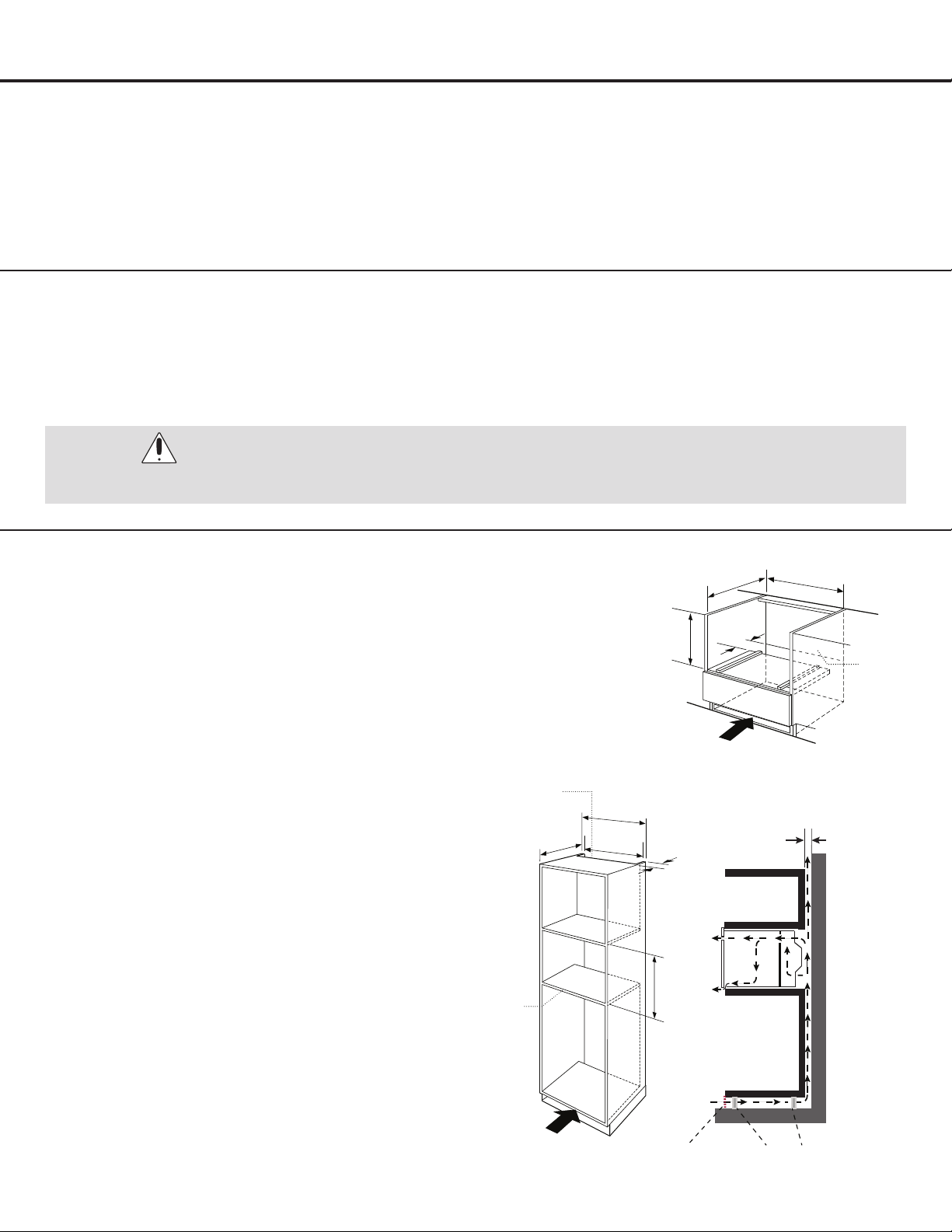
Preparing the Cabinet
•This appliance is only intended to be fully tted in a
kitchen.
•This appliance is not designed to be used as a tabletop
appliance or inside a cupboard.
•The tted cabinet must not have a back wall behind the
appliance.
•A gap of at least 45 mm must be maintained between the
wall and the base or back panel of the unit above.
•The tted cabinet must have a ventilation opening of 250
cm
2
on the front. To achieve this, cut back the base panel
or t a ventilation grille.
•Ventilation slots and intakes must not be covered.
•The safe operation of this appliance can only be
guaranteed if it has been installed in accordance with
these installation instructions.
•The installer is liable for any damage resulting from
incorrect installation.
•The cabinet into which the appliance is tted must be
heat resistant up 90°C.
•Note: There should be gap above the oven.
WARNING:
DO NOT LIFT THE UNIT BY THE OVEN DOOR HANDLE.
FLOOR
Cupboard feetVentilation grid
Rear ventilation
opening, min. 250 cm²
W
A
L
L
Ventilation area in the
base min. 250 cm²
56 cm (22”)
+0.8 (0.3”)
60 cm (23.6”)
Min. 55 cm
(21.6”)
Back panel
opening
Min. 4.5 cm
(1.75”)
Min. 4.5 cm
(1.75”)
45 cm
(17.7”)
Ventilation area
in the base min.
250 cm²
56 cm (22”)
+0.8 (0.3”)
Min. 55 cm
(21.6”)
Back panel
opening
46 cm
(18.1”)
5 cm
(1.9”)
Figure 1
Loading ...
Loading ...
Loading ...