
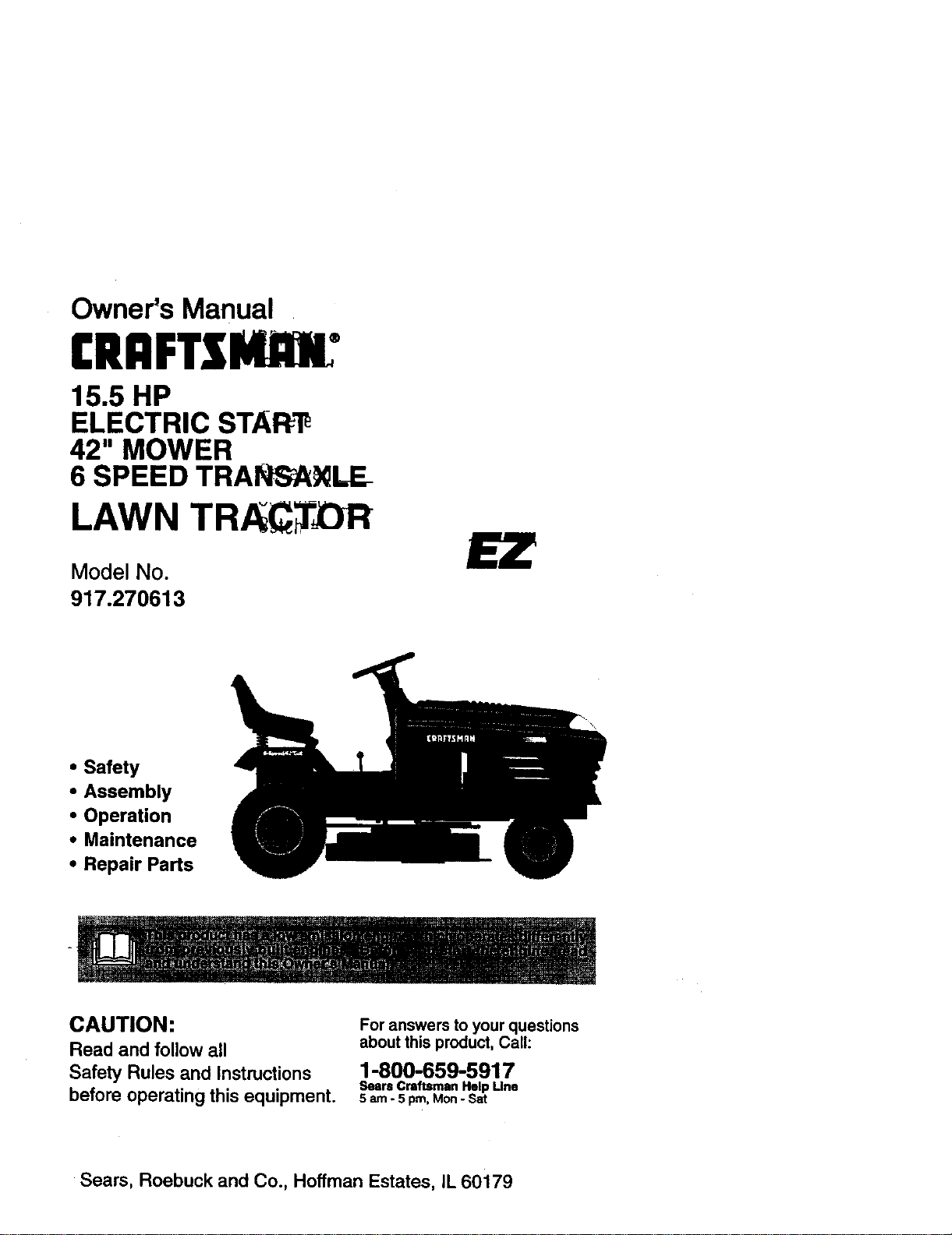
Owner's Manual
CRRFT$I4nH"
15.5 HP
ELECTRIC STAR_
42" MOWER
6 SPEED TRANSA_LE
LAWN TR. f TX3R
Model No.
917.270613
• Safety
• Assembly
• Operation
• Maintenance
• Repair Parts
_,-- .............. r' "" ........i II r
CAUTION:
Read and follow all
Safety Rules and Instructions
before operating this equipment.
For answers to your questions
about this product, Call:
1-800-659-5917
Sears Craftsman Help Une
5 am - 5 pro, Mon- Sat
Sears, Roebuck and Co., Hoffman Estates, IL 60179
W_ .................................. ,,,.,..°,.*..°.2
Safety Rules...........................................2
Productspec _..O.n_s............................5
Assembly..................:.............................8
Operation............................................. 11
MaintenanceSchedule.........................17
Maintenance.........................................17
ServiceandAdjustments......................21
Storage.................................................27
Troubleshooting....................................28
RepairParts.........................................32
PartsOrdering.......................BeckCover
LIMITED TWOYEAR WARRANTYON CRAFTSMAN RIDING EQUIPMENT
Fortwo(2) yearsfrom thedateofpurchase,ifthisCraftsmanRidingEquipmentismain-
tained,lubricatedandtunedupaccordingtotheinstructionsintheowner'smanual,
Searswillrepairor-rsplsce,free ofcharge,anypartsfound tobedefectivein materialor
worla'nanship.
ThisWarrantydoesnotcover:.
• Expendableitemswhichbecomeworndudngnormaluse,suchas blades,spark
plugs,air cleaners,belts,etc.
• Tiro replacementorrepaircausedbypuncturesfrom outsideobjects,suchas nails,
thorns,stumps,or glass.
• Repairsnecessarybecauseof operatorabuse,negligence,improperstorageoracci-
dent orthefailureto maintaintheequipmentaccordingtotheinstructionscontainedin
theowner'smanual.
• Ridingequipmentusedfor commsrciaior rentalpurposes.
LIMITED 90 DAYWARRANTYON BATTERY
Forninety(90) days fromdateofpurchase,ifany batteryincludedwiththisridingequip
mentprovesdefectivein materialorworkmanshipand ourtestingdeterminesthe bat-
terywillnotholda charge,Searswillreplacethebatteryat nocharge.In-homewarranty
serviceon yourCraftsmanridingequipment is availableat no chargefor 30 daysfrom
thedateofpumhese.Pleasecontactyournearestservicecenter.After30 daysfromthe
dataofpurchase,warrantyservice isavailablebytakingyourCraftsmanridingequip-
menttoyournearestSears ServiceCenter.(In-homewarrantyservicewillstillbeavail-
ableafter 30 days from thedate ofpurchasebuta standardtripchargewillapply).This
warrantyappliesonlywhilethis productisinthe UnitedStates.ThisWarrantygivesyou
specificlegalrights, and youmayalsohave otherrightswhichmay varyfromstateto
state.
Sears, RoebuckandCo., D/817 WA,HoffmanEstates,IL 60179
GENERAL OPERATION
• Read,understand,and followail instruc-
tionsinthemanuai andon the machine
beforestarting.
• Onlyallowresponsibleadults,whoare
familiarwiththe instructions,tooperate
the machine.
• Clearthearea ofobjectssuchas rocks,
toys,wire, etc., whichcouldbepicked
up andthrownbytheblade.
• Be surethe areais clearofotherpeople
before.mowing"Stop machineifanyone
entersthe area.
• Nevercarrypassengers.
• Do notmowinreverseunlessabsolute-
lynecessary.Alwayslookdawn and
behindbeforeand whilebacking.
• Beawareofthemowerdischargedirec-
tionanddo notpoint it at anyone. Do
notoperatethe mowerwithouteither
the entiregrasscatcher orthe guardin
place.
• Slowdawn beforetuming.
• Neverleavea running machine unat-
tended.Alwaystum offblades,set park-
ingbrake,stopengine,and remove
keysbeforedismounting.
2
•Tum otf blades when not rnowing.
• Stop engine before removing grass
catcher or unclogging chute;
• Mowonly indeylight orgeed arlir_al
Ikjht.
• Do not operate the machine while under
. the influence of alcohol or drugs.
• Watch for treffic when operating near or
crossing roadways.
• Use extra care when loading or unload-
ing the machine intoa trailer or truck.
SLOPE OPERATION
Slopes are a major factor related to Ioas-
of-control and tipover accidents, which
can result in severe injury or death. All
slopes require extra caution. If you cannot
back up the slope or ifyou feel uneasy on
it, do not mow it.
DO:
• Mow up and down slopes, not across.
• Remove obstacles such as rocks, tree
limbs, etc.
• Watch for holes, ruts, or bumps. Uneven
terrain could overtum the machine. Taft
grass can hide obstacles.
• Use slow speed. Choose a low gear so
that you wifl not have to stop or shift
while on the slope.
• Follow the manufacturer's recommen-
dations for wheel weights or counter-
weights to improve stability.
• Use extra care with grass catchers or
other attachments. These can change
the stability of the machine.
• Keep all movement on the slopes slow
and gradual. Do not make sudden
changes in speed or direction.
• Avoid.starting or stopping on a slope. If
tires inse traction, disengage the blades
and proceed slowly strsight.down the
slope.
DO NOT:
• Do nottum on slopes unless necessary,
and then, turn slowly and gradually
downhill, if possible.
• Do notmow near dropoffs, ditches, or
embankments. The mower could sod-
denly tum over if a wheel isover the
edge of a cliff or ditch, or if an edge
caves in.
• Do nog__mowon wet grass. Reduced
traction could cause sliding.
• Do nottryto stabUizethe mach_e by
putting your foot on the ground.
• Do not ose grees catcher on 8tesp
slopes.
CHILDREN
Tragic accidents can occur if the operator
is not alert to the presence of children.
Children are oftefl a_ to the
machine and the mowing activity. Never
assume that children will remain where
you last saw them.
• Keep children out of the mowing area
and under the watchful care of another
responsible adult.
• Be alert and turn machine off if children
enter the area.
• Before and when backing, look behind
and down for small children.
• Never carry children. They may fall off
and be seriously injured or interfere with
safe machine operation.
• Never allow children to operate the
machine.
• Use extra care when approaching blind
comers, shrubs, trees, or other objects
that may obscure vision.
SERVICE
• Use extra care In handling gasoline and
other fuels. They are flammable and
vapors are explosive.
Use only an approved container.
Never remove gas cap or add fuel
with the engine running. Allow en-
gine to cool before refueling. Do not
smoke.
Never refuel the machine indoors.
Never store the machine or fuel
container inside where there is an
open flame, such as a water heater.
• Never run a machine inside a closed
area.
• Keep nuts and bolts, especially blade
attachment bolts, tight and keep equip
ment in good condition.
• Never tamper with safety devices.
Check their proper operation reguledy.
• Keep machine free of grass, leaveS, or
other debds build-up. Clean oil or fuel
spillage. Allow machine to cool before
stodng.
• Stop and inspect the equipment if you
strike an object. Repair, If necesssPJ,
before restarting.
3
• Never makeadjustmentsorrepairswith
theenginerefining.
• Grasscatchercomponentsam subject
towear,damage,and deterioration,
whichcouldexposemovingpartsor
allowobjectstobethrown. Frequently
checkcomponents and replacewith
reanufacturer's recommendedpads,
when necessary.
• Mower blades are sharp and can cut.
Wrap the blade(s) or wear gloves, and
use extra caution when servicing there.
• Check brake operation frequently.
Adjust and service as required.
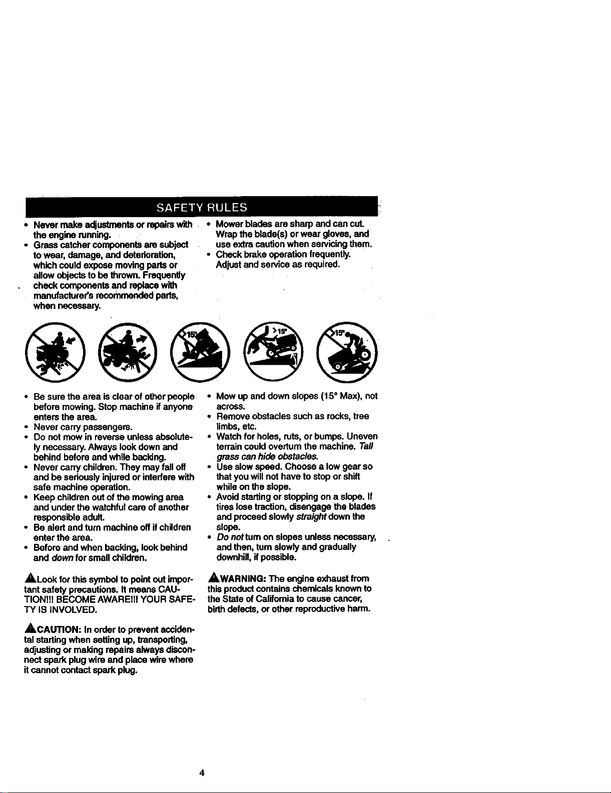
• Mow up and down slopes (15 ° Max), not
across.
• Remove obstacles such as rocks, tree
limbs, etc.
• Watch for holes, ruts, or bumps. Uneven
terrain could overturn the machine. Tall
graSs can hide obstacles.
• Use slow speed. Choose a low gear so
that you will not have to stop or shift
while on the slope.
• Avoid starting or stopping on a slope. If
tires lose traction, disengage the blades
and proceed slowly straight down the
slope.
• Do nottum on slopes unless necessary,
and then, tam slowly and gradually
downhi,, if poseible.
• Besurethearea isclear ofotherpeople
beforemowing. Stopmachine ifanyone
entemthe area.
• Never carrypassangem.
• Do notmowin reverseunlessabsolute-
lynecessary.Alwayslookdown and
behindbeforeandwhile backing.
• Never carrychildren.They mayfall off
and beseriouslyinjuredorinterferewith
safe machineoperation.
• Keepchildren outofthe mowingarea
and underthewatchfulcare ofanother
respor,sib_eadutt.
• Be alertandturnmachineoffifchildren
enterthearea.
• Beforeand whenbecking, lookbehind
and downforsmallchildren.
ALook forthissymboltopointoutimpor-
tantsafetyprecautions.It meansCAU-
TIONI!! BECOMEAWAREIIIYOUR SAFE-
TY IS iNVOLVED.
_,WARNING: The engine exhaust from
this product contains chemicals known to
the State of Callfomia to cause cancer,
birthdefects, or other reproductive harm.
_,CAUTION: In ordertopreventacciden-
talstartingwhensetting up,transpo_ng,
adjustingor makingrepairsalwaysdiscon-
nectsparkplugwireand placewirewhere
itcannotcontaCtsparkplug.
4
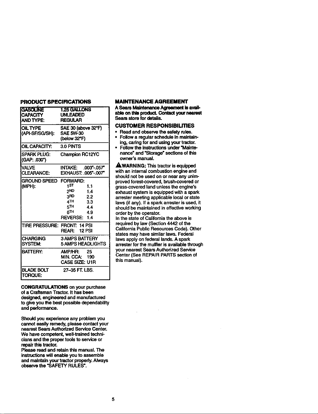
PRODUCT SPECIFICATIONS
GASOU_ 1.25 GALLONS
CAPACITY UNLEADED
AND TYPE: REGULAR
OIL'WPE SAE30 (above32_F)
_,PI-SF/SG/SH): SAE5W-30
(below32"F)
OILCAPACITY: 3.0 PINTS
3PARKPLUG: ChampionRC12YC
_AP:;030")
_/ALVE INTAKE: .003"-.057'
3LEARANCE: EXHAUST:.005"-.00"/"
3ROUND SPEED FORWARD:
VIPH): 1ST 1.1
2ND 1.4
3RD 2.2
4TM 3.3
5TM 4.4
6TM 4.9
REVERSE: 1.4
]'IRE PRESSURE: FRONT: 14 PSI
REAR: 12 PSI
3HARGING 3AMPS BA'I-I'ERY
SYSTEM: 5AMPS HEADLIGHTS
E3ATTERY: AMP/HR: 25
MIN. CCA: 190
CASE SIZE: U1R
BLADE BOLT 27-35 FT. LBS.
TORQUE:
CONGRATULATIONS on your pumhase
of a Craftsman Tractor. It has been
designed, engineered and manufactured
to give you the best possible dependability
and performance.
Should youexpedenceanyproblemyou
cannoteasilyremedy,please contactyour
nearestSearsAuthorizedSewloe Center.
We havecompetent, welt-trainedtechni-
ciansandthepropertoolstoservice or
repairthistractor.
Pleaseread and retainthis manual.The
instructionswillenableyoutoassemble
andmaintainyourtractorproperly.Always
observethe =SAFETYRULES'.
MAINTENANCE AGREEMENT
ASeara _ Agreementisavail-
able onthisproduct.Cent=rotyournearest
Searestore fordetails.
CUSTOMER RESPONSIBILITIES
• Read and observe the safety roles.
• Follow a regular schedule in maintain-
ing, cadng for and using your tractor.
• Follow the instructions under "Malnta-
nance" and "Storage" sections ofthis
owner's manual.
,_WARNING: This tractor is equipped
with an internal combustion engine and
should not be used on or near any unim-
proved forest*covered, bnJsh-covered or
grass-covered land unless the engine's
exhaust system is equipped with a spark
arrester meeting applicable local or state
laws (if any). If a spark arrester is used, it
should be maintained in effective working
order by the operator.
In the state of California the above is
required by law (Section 4442 of the
California Public Resources Code). Other
states may have similar laws. Federal
laws apply on federal lands. A spark
arrester for the muffler is available through
your nearest Sears Authorized Service
Center (See REPAIR PARTS section of
this manual).
5
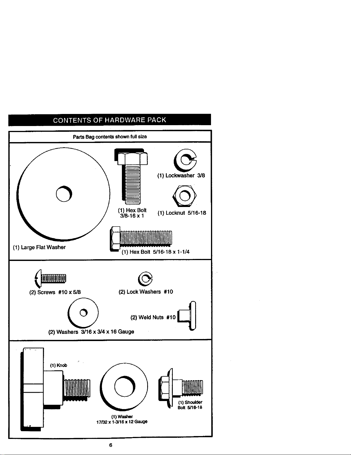
(1) Large Flat Washer
Parts Bag contentsshownfull size
®
(1) Lockwasher 3/8
(1) Hex Bolt
3/8o16x 1
@
(1) Locknut 5/16-18
_x 1-1/4
(2) Screws #10 x 5/8
(2) LockWashers #10
(2) Weld Nuts 010 I_
(2) Washers 3/16 x 3/4 x 16 Gauge
m
i
i
(1) Knob
©
(1)Washer
17/32x 1-3/16x 12 Gauge
(1) Shoulder
Bolt 5/16-18
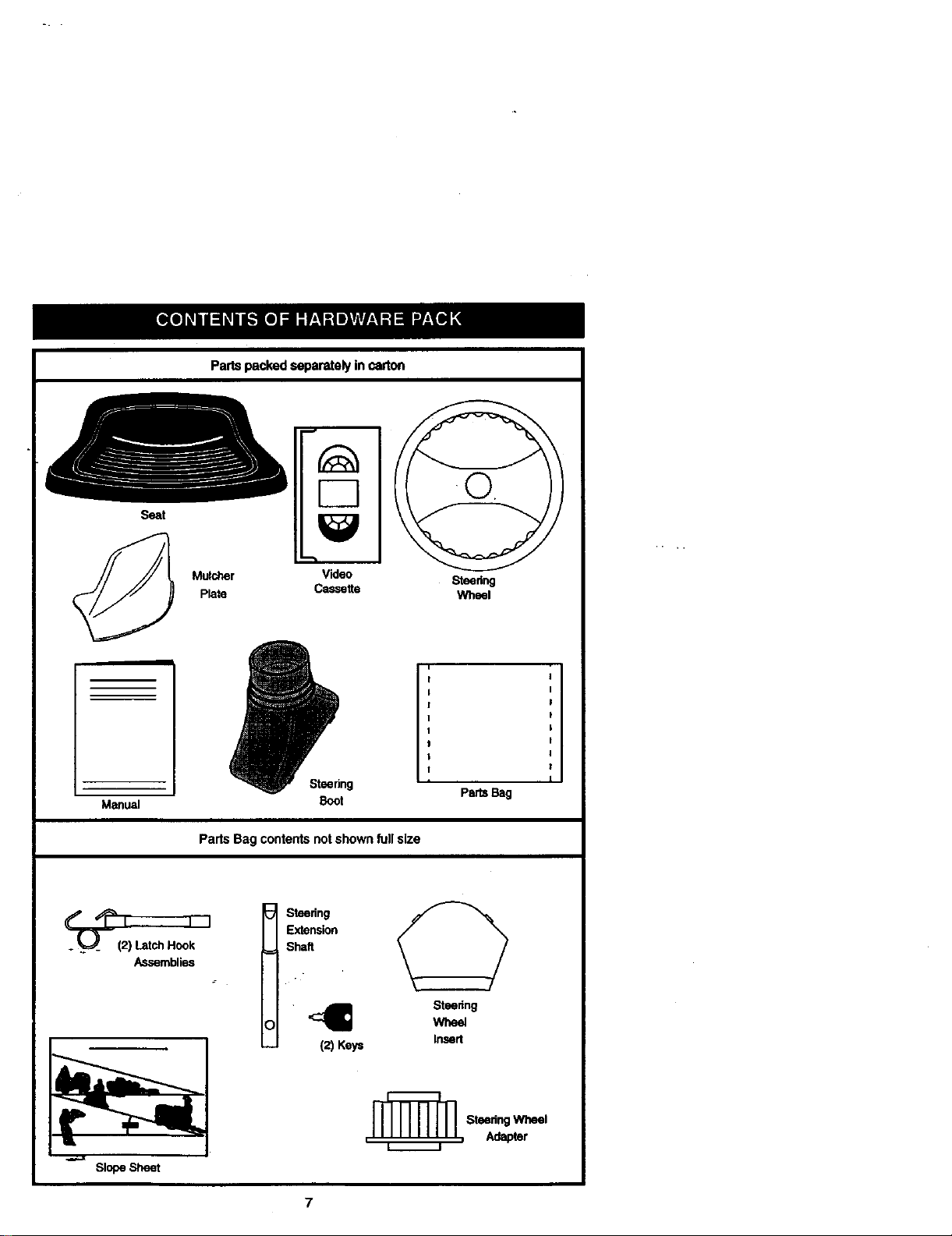
Seat
Partspacked separately in carton
J
Muk:her Video
Plate Cassette
Steor;ng
Wheel
Manual
Steering
Boot
Parts Bag contentsnotshown fullsize
Parts Bag
I
Shaft
12)Keys
Siope Sheet
Steering
Wheel
Insert
Steodng Wheel
, , Adapter
7
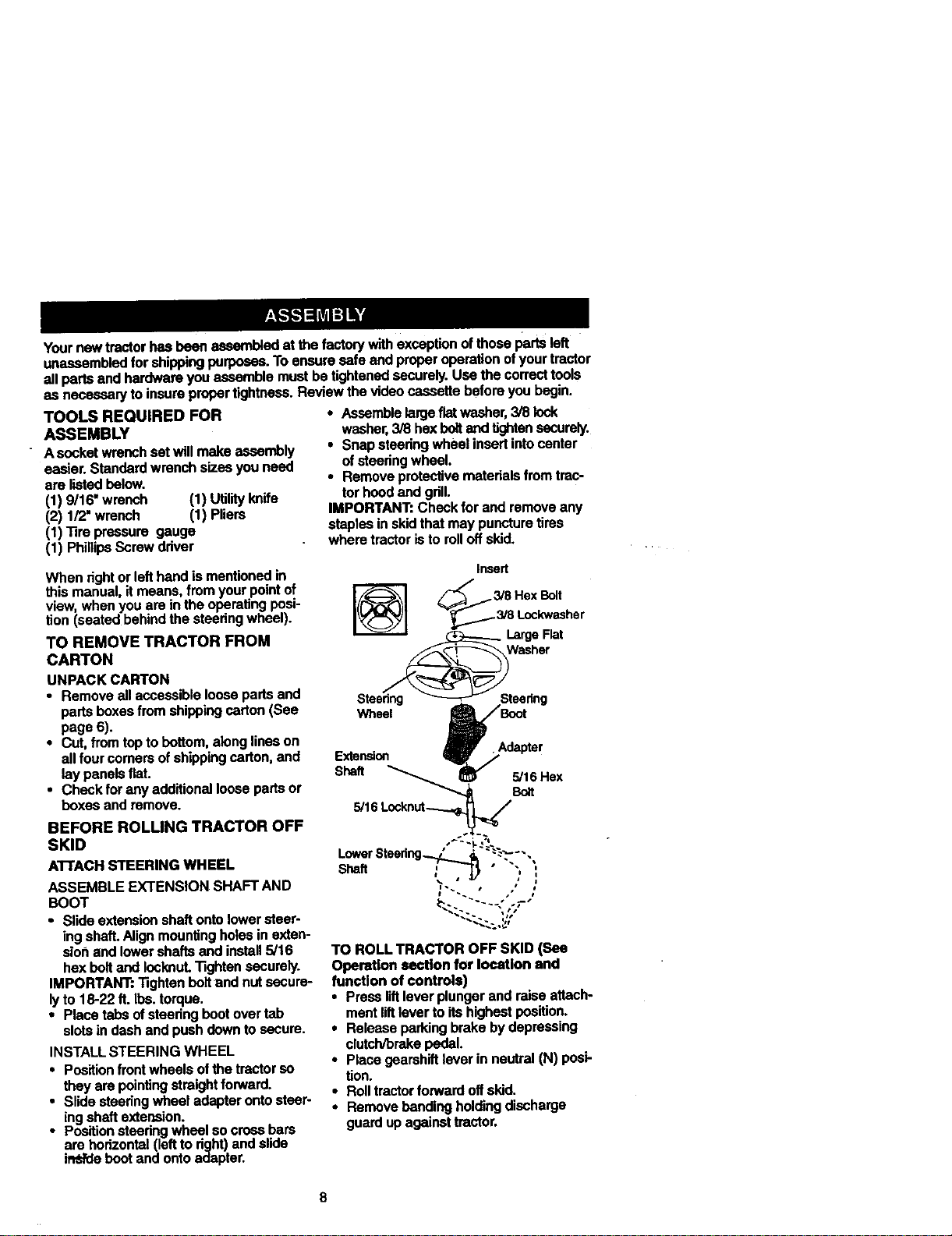
Yournowtractorhasbeenassembledatg_efactorywithexceptionofthosepadsleft
unassembledforshippingpurposes.Toensuresafeandproperoperationofyourtractor
allparts and hardware you assemble must be tightened securely. Use the correct tools
as necessary to insure proper tightness. Review the video cassette before you begin.
TOOLS REQUIRED FOR
ASSEMBLY
" Asocketwrenchsetwillmakeassembly
easier.Standardwrenchsizesyouneed
are listedbelow.
(1) 9/16"wrench (1) Utilityknife
(2) 1/2"wrench (1) Pliers
(1) _re pressure gauge
(1) PhillipsScrewdriver
When rightor lefthandismentionedin
thismanual,itmeans fromyourpointof
view,whenyou arein theoperatingposi-
tion(seatedbehindthesteeringwheel).
TO REMOVE TRACTOR FROM
CARTON
UNPACK CARTON
• Remove all accessible loose pads and
parts boxes from shipping carton (See
page 6).
• Cut, from top to bottom, along lines on
all four comers of shipping carton, and
lay panels flat.
• Check for any additional loose parts or
boxes and remove.
BEFORE ROLUNG TRACTOR OFF
SKID
ATrACH STEERING WHEEL
ASSEMBLE EXTENSION SHAFTAND
BOOT
• Slideextensionshaftontolowersteer-
ingshaft.Alignmountingholesin exten-
sionand lowershaftsand install5/16
hexboltand IncknuL_ghten securely.
IMPORTANT:Tightenboltand nutsecure-
lyto 18-22ft. Ibs.torque.
• Placetabsofsteeringbootovertab
slotsin dashandpushdowntosecure.
INSTALLSTEERING WHEEL
• Positionfront wheelsofthe tractorso
they arepointingstraight forward.
• Slidesteeringwheel adapterontosteer-
ingshaftextension.
• Positionsteeringwheel socrossbars
arehorizontal(leftto dght)andslide
ir_e bootand ontoadapter.
• Assemble large flatwasher, 3/8 lock
washer, 3/8 hex belt and tighten securely.
• Snap steering wheel insert into center
of steering wheel.
• Remove protective materials from trac-
tor hood and grill.
IMPORTANT: Check for and remove any
staples in skid that may puncture tires
where tractor isto roll off skid.
Insert
'_ F'_ 3/8 Hal Bolt
_3/8 I.._asher
Stee_teedng
Wheel _t
Extension _JF Adapter
Shaft "'"---,...,.,_ i_ Hex
5/16 Lonlm_ o__ /
LowerSteedng......_/ _, "%'_--.
• • _ J i
t _. , t
TO ROLL TRACTOR OFF SKID (See
Operation soctlon for location and
function of controls)
• Press liftlever plunger and raise attach-
ment liftlover to its highest position.
• Release parking brake by depressing
clutch/brake pedal.
• Place gearshift lever in neutral (N) posi-
tion.
• Roll tractor forward off skid.
• Remove banding holding discharge
guard up against tractor.
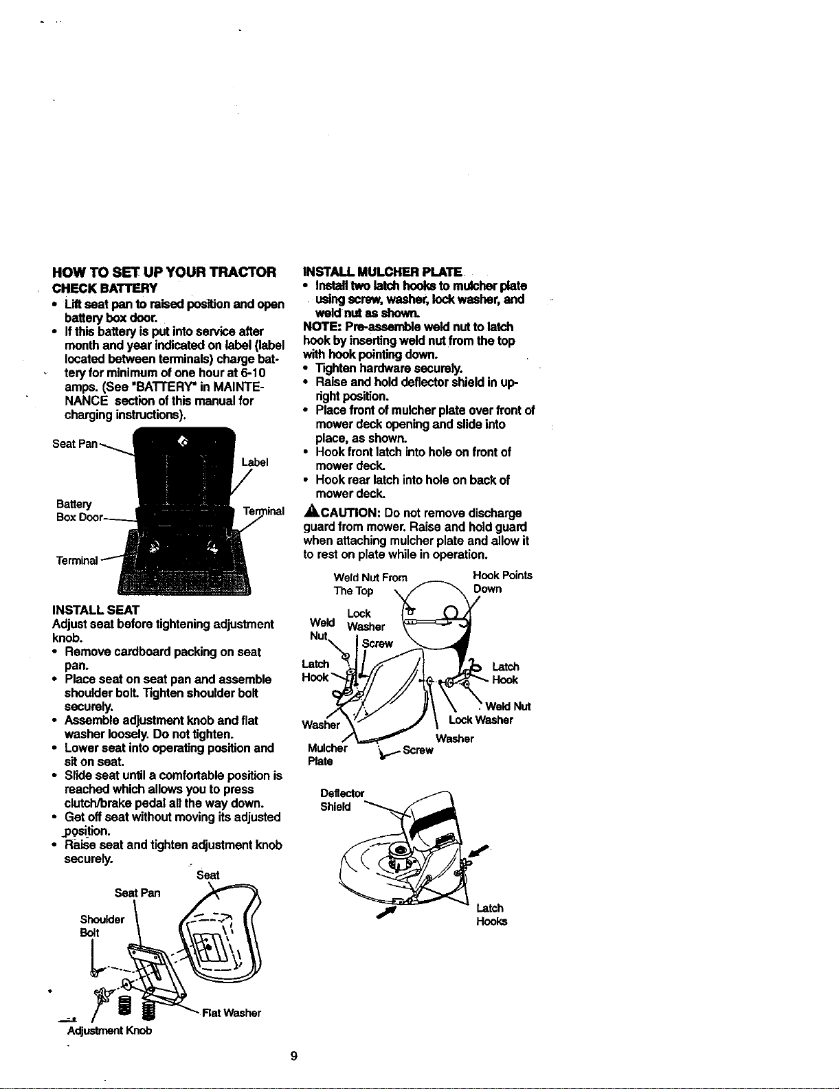
HOW TO SET UP YOUR TRACTOR
CHECK BATTERY
• Liftseat pan toraisedpos_dionandopen
battelyboxdoor.
• It thisbatteryisput into se_ice after
monthandyear indicatedonlabel(label
iocated between termi_ls) chargebat-
teryforminimumofonehourat 6-10
amps.(See "BA'I-rERY=in MAINTE-
NANCE sectionofthismanual for
charginginstructions).
Seat Pan
Label
Battery
Be
INSTALL SEAT
Adjust seat before tightening adjustment
knob.
• Remove cardboard packing on seat
pan,
• Place seat on seat pan and assemble
shoulder boll -Rghten shoulder bolt
securely.
• Assemble adjustment knob and flat
washer loosely. Do not tighten.
• Lower seat into operating position and
sit on seat.
• slide seat un_l a comfortable position is
reached which allows you to press
clutch/brake pedal all the way down.
• Get off seat without moving its adjusted
,position.
• R_,_e seat and tighten adjustment knob
securely.
- Seat
Seat Pan
Shoulder
Belt
INSTALL MULCHER PI.ATE
• instafltwolatch boolw tomusher plata
using screw,washer,lockwasher,and
weld nutas shown.
NOTE: pre-aasembleweld nutto latch
hookbyinsertingweldnutfromthetop
withhookpointingdown.
• Tightenhardwaresecurely.
• Raiseandholddeflectorshieldinup-
rightpos'_on.
• Placefrontofmuicherplateoverfrontof
mowerdeckopeni_Jandslideinto
place,as shown.
• Hookfrontlatchintoholeonfrontof
mowerdeck.
• Hookrear latchintoholeon backof
mowerdeck.
,_CAUTION: De notremovedischarge
guardfrom mower.Raiseand holdguard
whenattachingmuicherplate andallow it
toreston platewhilein operation.
Weld Nut From Hoot( Points
The Top _o'_
Lock [_J
Weld Washer _ "_
Nut'x_ Screw _X_ tch
D\\ \weld.ut
Washer
M_cher '_ Screw
Plate
Deflector __
Shield
Adjustment Knob
Washer
TO CONVERT TO BAGGING OR DIS-
CHARGING
Simplyremovemulcherplateandstorein
a safe place.Yourmowerisnowreadyfor
dischargingor installationofoptional
grasscatcheraccessory.
NOTE: It is notnecessarytochange
blades.The mulcherbladesaredesigned
for dischargingand baggingalso.
_HECK TIRE PRESSURE
The tireson yourtractorwere overinflated
atthefactory forshippingpurposes.
Correcttire pressureisimportantfor best
cu_ingperformance.
• Reducetirepressureto PSI shownin
=PRODUCTSPECIFICATIONS"on
page 5 ofthismanual.
CHECK DECK LEVELNESS
Forbestcuttingresults,mowerhousing
shouldbe propedyleveled.See "TO
LEVELMOWER HOUSING"inthe
ServiceandAdjustmentssectionofthis
manual.
CHECK FOR PROPER PosmoN OF
ALL BELTS
See thefiguresthatareshownforreplac-
ingmotionand mowerbladeddvebelts in
the ServiceandAdjustmentssectoinof
thismanual.Verifythatthe beltsare mut-
ed correctly.
CHECK BRAKE SYSTEM
Afteryoulearnhowto operateyourtrac-
tor,checktosee thatthe brakeispropedy
adjusted.See "TOADJUST BRAKE"in
the Serviceand Adjustmentssectionof
this manual.
/ CHECKLIST
PLEASE REVIEW THE FOLLOWING
CHECKLIST:
/ All assembly instructionshave been
completed.
/ No remaining loose pads in carton.
,/ Battery is properly prepared and
charged. (Minimum 1 hour at 6 amps).
,/ Seat is adjusted comfortably and
tightened securely.
•/" All tires are properly inflated. (For
shipping purposes, the tires were
ovednflated at the factory).
,/ Be sure mower desk is propedy leveled
side-to-side/front-to-rear for best
cutting results. ('Rres must be propedy
inflated for leveling).
4" Check mower and drive belts. Be sure
they are muted propedy around pulleys
and inside all belt keepers.
,/ Check widng. See that all connections
are still secure and wires are properly
clamped.
WHILE LEARNINGHOW TO USE YOUR
TRACTOR, PAYEXTRAATTENTION TO
THE FOLLOWINGIMPORTANTITEMS:
/ Engineoilisat properlevel.
,/ Fueltankisfilled withfresh, clean,
regularunleadedgasoline.
,/ Becomefamiliarwithall controls- their
locationand function. Operatethem
beforeyoustarttheengine.
4" Besurebrakesystemisin safe
operatingcondition.
10
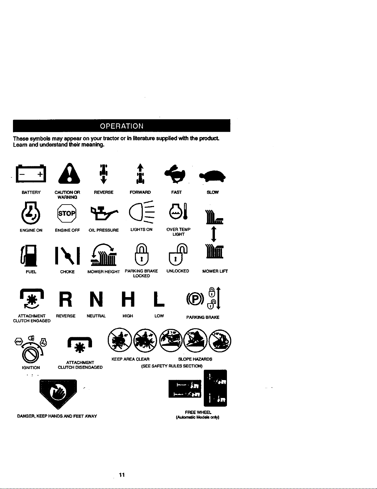
These symbolsmayappearonyourtractororin literaturesuppliedwiththeproduct.
Leamand understandtheir meaning.
&
BATTERY CAUTION ON REVERSE FORWARD FAST SLOW
WARNINQ
ENGINE ON ENGINE OFF OIL PRESSURE LIGHTS ON OVELRTEMP t
FUEL CHOKE MOWER HEIGHT PARKING BRAKE UNLOCKED MOWER LIFT
LOCKED
r_'_ R N H L
ATTACHMENT REVERSE NEUTRAL HIGH LOW pARKING BRAKE
CLUTCH ENGAGED
KEEP AREA CLEAR SLOPE HAZARDS
ATTACHMENT
IGNmON CLUTCH DISENGAGED
DANGER, KEEP HANDS AND FEET AWAY
(SEE SAFETY RULES SECTION)
FREEWHEEL
11
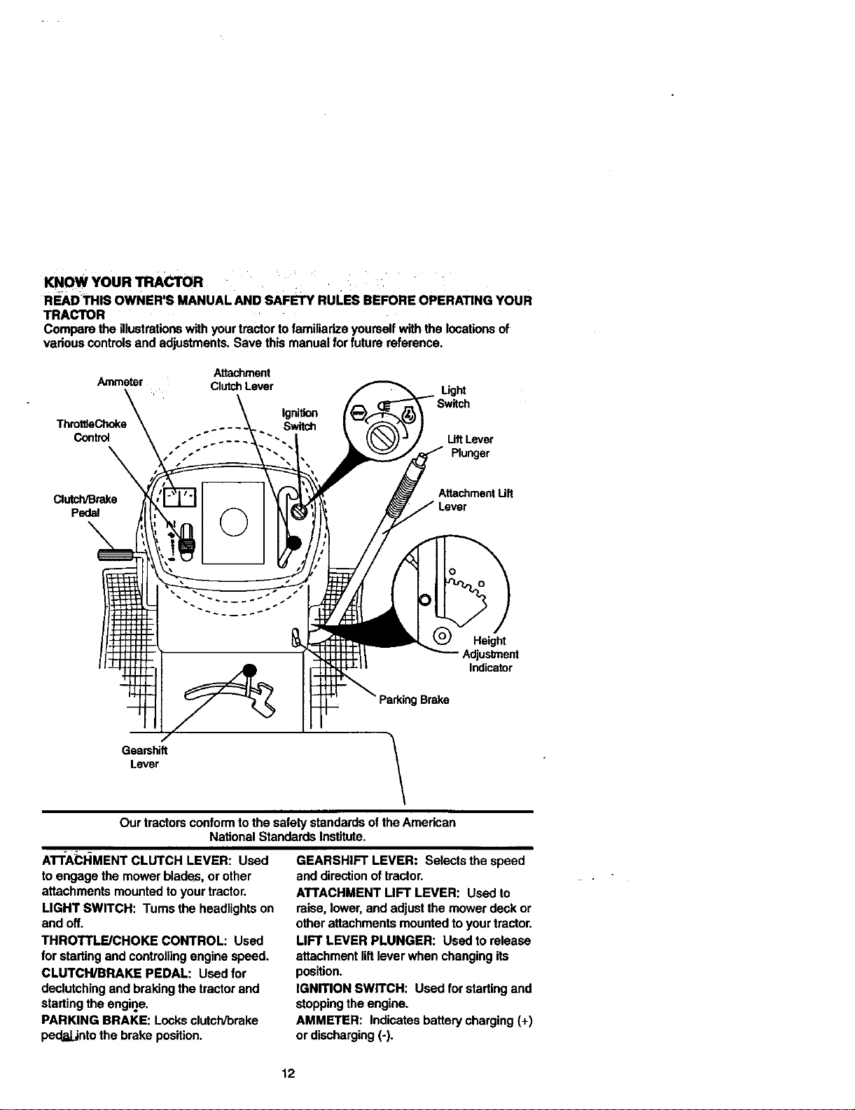
KNOW YOUR TRACTOR
R_D THIS OWNER'S MANUALAND SAFETY RuLEs BEFORE OPERATING YOUR
TRACTOR
Compare the illustrations with your tractor to familiarize yourself with the locations of
various controls and adjustments. Save this manual for future reference.
Attachment
Ammeter ClutchLever Light
Ignition
ThrottleChoke Switch
Control LiftLever
Plunger
Clutch/Brake
Pedal
Attachment Uft
Height
Adjustment
Indicator
Brake
Gearshift
Lever
Ourtractorsconformto thesafetystandardsoftheAmerican
NationalStandardsInstitute.
A'r'rA_3HMENT CLUTCH LEVER: Used
to engage the mower blades, or other
attachments mounted to your tractor.
LIGHT SWITCH: Tums the headlights on
and off.
THROTTLE/CHOKE CONTROL: Used
for starting and controlling engine speed.
CLUTCH/BRAKE PEDAL: Used for
declutching and braking the tractor and
starting the engine.
PARKING BRAKE: Locks clutch/brake
ped_LJntothe brake position.
GEARSHIFT LEVER: Selects the speed
and direction of tractor.
ATTACHMENT LIFT LEVER: Used to
raise, lower, and adjust the mower deck or
other attachments mounted to your tractor.
LIFT LEVER PLUNGER: Used to release
attachment liftlever when changing its
position.
IGNITION SWITCH: Used for starting and
stopping the engine.
AMMETER: Indicates battery charging (+)
or discharging (-).
12
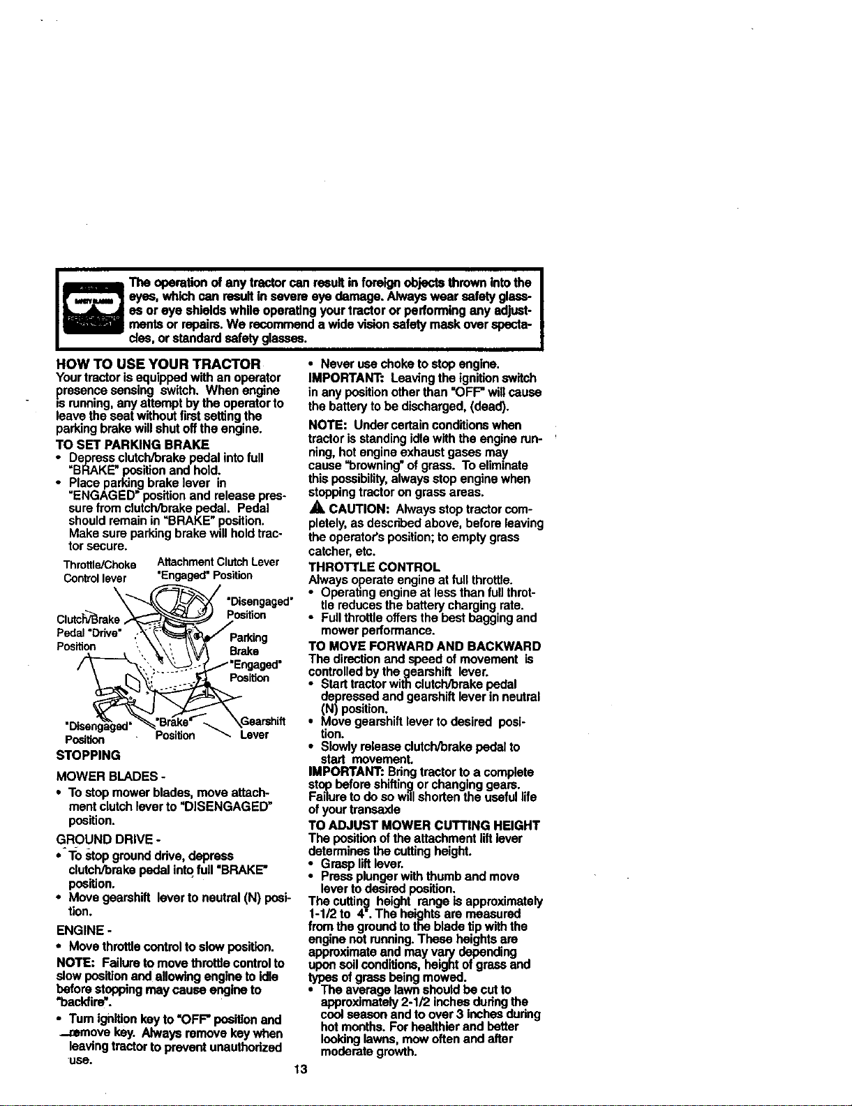
HOWTOUSEYOURTRACTOR
Yourtractorisequippedwithan operator
presence sensing switch. When engine
is running, any attempt by the operator to
leave the seat without first setting the
parking brake will shut off the engine.
TO SET PARKING BRAKE
i epress clutch/brake pedal into full
=BRAKE" position and hold.
Place par.kingbrake lever in
ENGAGED position and release pres-
sure from clutch/brake pedal. Pedal
should remain in "BRAKE" position.
Make sure parking brake will hold trac-
tor secure.
Throttle/Choke AttachmentClutchLever
Controllever "Engaged"Position
Clutc_rake
Pedal "Ddve"
Position
|
The operation of any tractor can result in foreige objects thrown intothe |
eyes, which can result in severe eye damage. Always wear safety glass-
I
es or eye shields while operating your tractor or performing any adjust-
manta or repairs. We recommend a wide vision safety mask over specta-
clse, or standard safety glasses.
"Disengaged"
Position
Brake
Position
STOPPING
Position
Position Lever
MOWER BLADES-
• Tostopmowerblades,moveattach-
mentclutchloverto "DISENGAGED"
position.
GROUND DRIVE-
•-To stopgrounddrive,depress
clutch/brakepedalintofull "BRAKE"
pusition.
• Movegearshiftlevertoneutral(N) posi-
tion.
ENGINE -
• Move throttlecontrol to slow position.
NOTE: Failure to move throttle control to
slow position and allowing engine to idle
before stopping may cause engine to
"back/ira'.
•Tum ignition key to "OFF" position and
r,,move key. Always remove key when
leaving tractor to prevent unauthodzed
use.
• Never use choke to stop engine.
IMPORTANT: Leaving the ignitionswitch
in any position other than =OFF" will cause
the battery to be discharged, (dead).
NOTE: Under certain conditions when
tractor is standing idlewith the engine run-
ning, hotengine exhaust gases may
cause =browning" of grass. To eliminate
this possibility,always stop engine when
stopping tractor on grass areas.
A CAUTION: Always stop tractor com-
pletely, as described above, before leaving
the operator's position; to empty grass
catcher, etc.
THROTrLE CONTROL
Always operate engine at full throttle.
• Operating engine at less than full throt-
tle reduces the battery charging rate.
• Full throttle offers the best bagging and
mower performance.
TO MOVE FORWARD AND BACKWARD
The direction and speed of movement is
controlled by the gearshift lever.
Start tractor with clutch/brake pedal
depressed and gearshift lever in neutral
(N) position.
• Move gearshift lever to desired posi-
tion.
• Slowly release clutch/brake pedal to
start movement.
IMPORTANT: Bdng tractor to a complete
stop before shifting or changing gears.
Failure to do so will shorten the useful life
ofyour transaxle
TO ADJUST MOWER CUTTING HEIGHT
The position ofthe attachment lilt lever
determines the cuffing height.
• Grasp lilt lever.
Press plunger with thumb and move
lever to desired position.
The cutting height range is approximately
1-1/2 to 4.'. The heights are measured
from the ground tothe blade tip with the
engine not running. These heights are
approximate and may vary depending
upon soilconditions, height ofgrass and
types of grass being mowed.
• The average lawn should be cut to
approximately 2-1/2 inches dudng the
cool season and to over 3 Inches dudng
hotmonths. For healthier and better
lookinglawns, mow often and after
moderate growth.
13
• Forbestcuttingperformance,grass
over6inchesInheightshouldbe
mewedtwice.Makethefirstcutrelative-
ly high;the second to desired height.
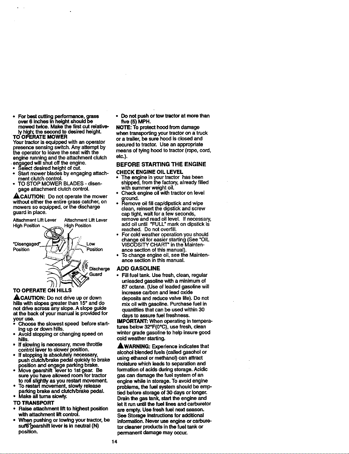
TO OPERATE MOWER
Your tractoris equipped with an operator
t_msenca sensing switch. Any attempt by
e operator to leave the seat with the
engine running end the attachment clutch
-engaged will shut off the engine.
• Select desired height of cut.
• Start mower blades by engaging attach-
ment clutch control.
• TO STOP MOWER BLADES - disen-
gage attachment clutch control.
_.CAUTION: Do not operate the mower
without either the entire grass catcher, on
mowers so equipped, or the discharge
guard in place.
AttachmentLiftLever AttachmentLiftLever
Hig HighPosition
Low
Position Position
• Do not push or tow tractor at mere than
five (5) MPH.
NOTE: To protect hood from damage
when transporting your tractor on a truck
or a trailer, be sure hood is closed and
secured to tractor. Use an appropriate
means of tying hood to tractor (rope, cord,
etc.).
BEFORE STARTING THE ENGINE
CHECK ENGINE OIL LEVEL
• The engine in your tractor has been
shipped, from the factory, already filled
with summer weight oil.
• Check engine oil with tractor on level
ground.
• Remove oilfill cap/dipstick and wipe
clean, reinsertthe dipstick and screw
cap tight, wait for a few seconds,
remove and read oil level. If necessary,
add oil until "FULL" mark on dipstick is
reached. Do not overfill.
• For cold weather operation you should
change oil for easier starting (See =OIL
VISCOSITY CHART" in the Mainten-
ance section of this manual).
• To change engine oil, see the Mainten-
ance section in this manual.
/ Guard
TO OPERATE ON HILLS
ACAUTION: DO not drive up or down
hills with slopes greater than 15= and do
not drive across any slope. A slope guide
at the back of your manual isprovided for
your use.
• Choose the slowest speed before start-
ing up or down hills.
• Avoldstopping or changing speed on
hills.
If slowing is necessary, move throttle
corltrollever to slower position.
If stopping is absolutely necessary,
push clutch/brake pedal _uickly to brake
position end engage perking brake.
Move gearshift lever to I st gear. Be
sure you have allowed room for tractor
to ronslighgy as you restart movement.
i To restart movement, slowly release
parking brake end clutcfVbrake pedal.
Make all turns slowly.
TO TRANSPORT
• Raise attachment liftto highest position
with attachment liftcontrol.
• When pushing or towing your tractor, be
surf"gearshift lever is in neutral (N)
position.
ADD GASOLINE
• Fillfuel tank. Use fresh, clean, regular
unleaded gasoline with a minimum of
87 octane. (Use of leaded gasoline will
increase carbon and lead oxide
deposits and reduce valve life). Do not
mix oil with gasoline. Purchase fuel in
quantities that can be used within 30
days to assure fuel freshness.
IMPORTANT: When operating in tempera-
tures below 32°F(0°C), use fresh, clean
winter grade gasoline to help insure good
cold weather starting.
AWARNING: Experience indicates that
alcohol blended fuels (called gasohol or
using ethanol or methanol) can attract
moisture which leads to separation and
formation of acids dudng storage. Acidic
gas can damage the fuel system of an
engine while in storage. To avoid engine
problems, the fuel system should be emp-
tied before storage of 30 days or longer.
Drain the gas tank, start the engine end
lot it run until_ fuel lines and carburetor
are empty. Use fresh fuel next season.
See Storage Instructionsfor additional
information. Never use engine or carbure-
tor cleaner products in the fuel tank or
permanent damage may occur.
14
_,CAUTION: Figto bottom of gas tank
filler neck. Do not ovedgl. Wlpe off any
spilled oil or fuel. Do not store, spill or use
gasoline near an open flame.
TO START ENGINE
When starting the engine for the flint time
or if the engine has run out of fuel, it will
take extra cranking time to move fuel from
the tank to the engine.
-- Sit on seat in operating position,
depress clutch/brake pedal and set
perking brake.
• Place gear shift lever in neutral (N) posi-
tion.
• Move attachment clutch to "DISEN-
GAGED" position.
• Move throttle control to choke position.
NOTE: Before starting, read the warm
and cold starting procedures below.
• Insert key into ignition and tum key
clockwise to =START" position and
release key as soon as engine starts.
Do not run starter continuously for more
than fifteen seconds per minute. Ifthe
engine does not start after several
attempts, move throttle control to fast
position, wait a few minutes and try
again. If engine stilldoes not start,
move the throttle control back to the
choke position and retry.
WARM WEATHER STARTING (50° F and
above)
• When engine starts, move the throttle
control to the fast position.
• The attachments and ground drive can
now be used. If the engine does not
accept the load, restart the engine and
allow it to warm up for one minute using
the choke as described above.
COLDWEATHERSTARTING ( 50° FAND
BELOW)
• Whenenginestarts,allowenginetorun
with.th.eJhrottlecontrolinthechoke
positionuntiltheenginerunsroughly,
thenmovethrottle controltofast posi-
tion.Thismay requireanenginewarm-
upperiodfrom severalsecondsto sev-
eralminutes,dependingon thetemper-
ature.
• The attachmentscanalsobe useddur-
ingthe enginewarm-upperiod.
NOTE: Ifat a highaltitude(above3000
feet) or incoldtemperatures(below32 F)
the carburetor fuel mixturemay needtobe
adjustedfor bestenginepedormance.
See "TOADJUSTCARBURETOR"In the
Se_and Adjustmentssectionofthis
manual.
15
NOTE: Ata highelUtude(above3000
feet) orIn coldtemperatures(below32 F)
the carburetor fuelmixturemay needtobe
adjustedforbestengineperformance.
See "TOADJUSTCARBURETOR"inthe
ServiceandAdjustmentssectionofthis
manual.
MOWING TIPS
• Tim chains cannot be used when the
mower housing is attached to tractor.
• Mower should be pmpedy leveled for
best mowing pedormance. See "TO
LEVEL MOWER HOUSING" in the
Service and Adjustments section ofthis
manual.
• The left hand side of mower should be
used for trimming.
• Drive so that clippings are discharged
onto the area that has been cut. Have
the cut area to the right ofthe machine.
This will result in a more even distribu-
tion of clippings and more uniform cut-
ting.
• When mowing large areas, stad by turn-
ing to the right so that clippings will dis-
charge away from shrubs, fences, drive-
ways, etc. After one or two rounds,
mow in the opposite direction making
left hand turns untilfinished
• Ifgrass is extremely tall, it should be
mowed twice to reduce load and possi-
ble fire hazard from dried clippings.
Make first cut relatively high; the second
to the desired height.
• Do not mow grass when it is wet. Wet
grass will plug mower and leave unde-
sirable clumps. Allow grass to dry
before mowing.
• Always operate engine at full throttle
when mowing to assure better mowing
performance and proper discharge of
material. Regulate ground speed by se-
lecting a low enough gear to give the
mower the best cutting pedormance as
well as the quality ofcut desired.
• When operating attachments, select a
ground speed that will suit the terrain
and give best pedormance of the at-
tachment being used.
MULCHINGMOWING TIPS
IMI_DRTAI/T: Forhest perlormance,
keepmowerhousingfreeofbuilt-upgrass
andtrash. Cleanafter eachuse.
• The specialmulchingbladewillrecut
thegrassclippingsmany timesand
reducethem in sizesothatastheyfall
ontothe lawnthey willdisperseintothe
grassand notbe noticed.Also,the
mulchedgrasswillbiodegradequickly
to providenutdantsforthelawn.
Alwaysmulchwithyourhighestengine
(blade)speedas thiswillprovidethe
bestrecuttingactionoftheblades.
• Avoidcuttingyourlawnwhenitiswet.
Wet grasstendstoform clumpsand
interfereswiththemulchingaction. The
besttimeto mowyourlawnis theearly
afternoon.Atthis timethegrasshas
driedandthe newlycutarea willnotbe
exposedtothe directsun.
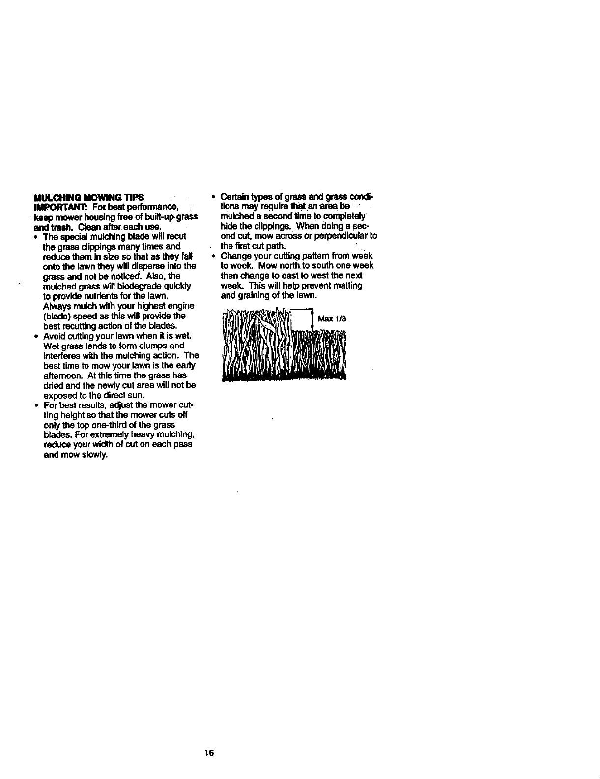
• Forbestresults,adjustthemowercut-
tingheightsothat themowercutsoff
onlythetopone-thirdofthegrass
blades.Forextremelyheavymulching,
reduceyourwidthofcutoneachpass
and mow slowly.
• Certaintypasofgressandgresscondi-
tionsmay requirethatan area he
mulched a secondtime to completely
hidetheclippings.Whendoinga Sac"
ondcut, mowacrossorperpendicularto
thefirstcutpath.
• Changeyourcuttingpatternfromweek
toweek. Mownorthtosouthoneweek
thenchange toeast towestthe next
week. Thiswillhelp preventmatting
andgrainingofthe lawn.
16
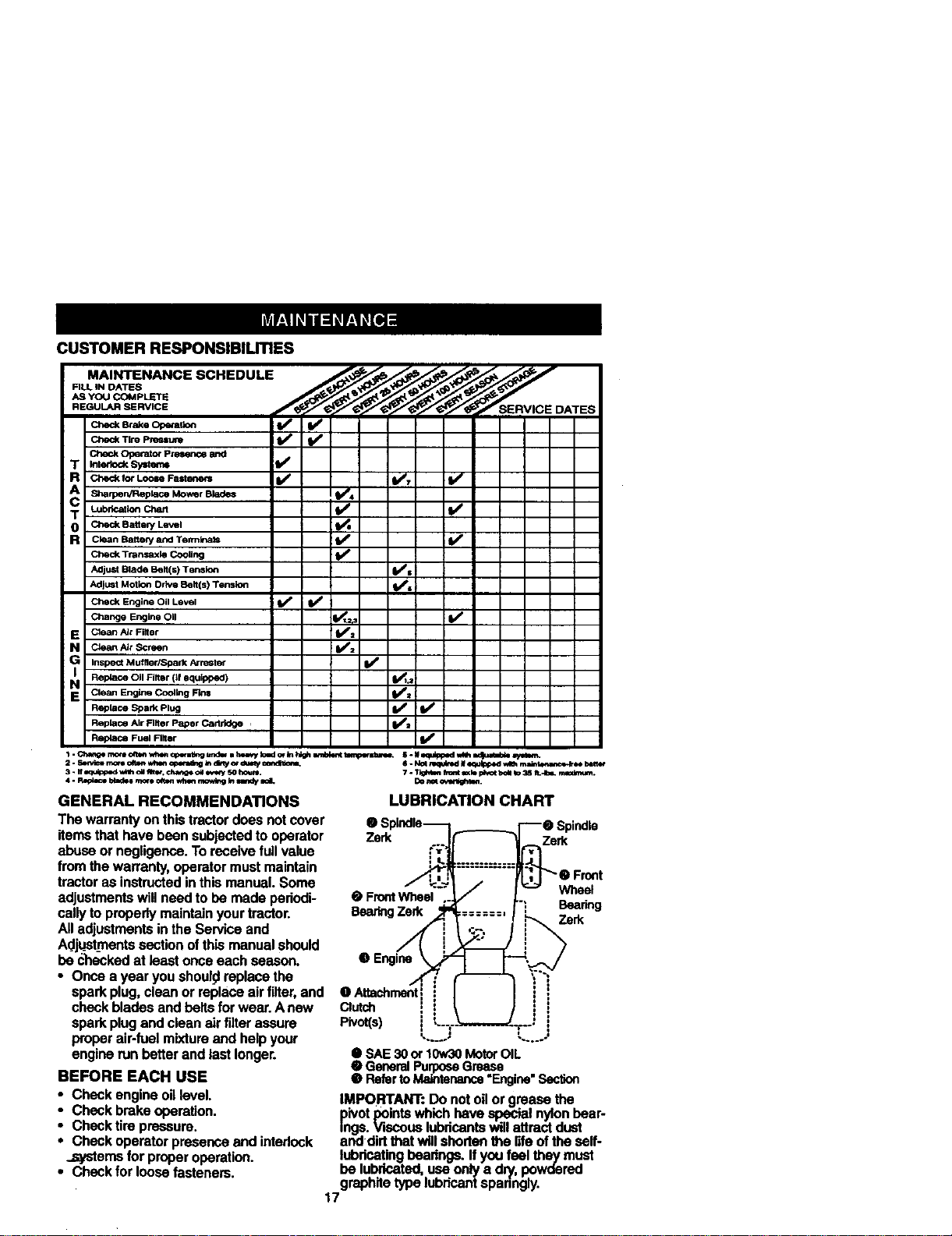
CUSTOMER RESPONSIBILITIES
FILL IN DATES
AS YOU COMPLETE
REGULAR SERVICE ATES
_o P_, iV' V"
Check Operator PzeS(n_ _
T _ede_ _ V'
R _ _orLee_ Fat=._== I/ V', It/
Sharpen/Replace Mower Blades IIf4
T _bri_ _ I/' I/
O Check Battely Lm/el
R Clean Batter/and Terrnlnats _ I_
Check Trar,.saxla Cooling ik_
Adjust Blade Belt(s) Tension (l_l
Ad)u=t Motion Drive Belt(s) Tension Ks
Check Engine O11Level ti_ V _
Change Engine Oil V*t._ _1_
E Claan Air Filter V*=
N Claan_r Screen I/=
G Inspect Muffier/_ark Nrester
Rep4ace Oil Filter Of equipped) I1_1.=
N CieenEnglneCoolingFins I,/=
Replace Spark Plug I_
Replace Air Filter Paper Cartridge , V*=
ReplaceFuelRlter
GENERAL RECOMMENDATIONS
The warranty on this tractor does notcover
items that have bonn subjected to operator
abuse or negligence. To receive full value
from the warranty, operator must maintain
tractor as instructed in this manual. Some
adjustments will need to be made pedodi-
cally to properly maintain your tractor.
All adjustments in the Service and
Adju_stmentssection ofthis manual should
be c'hecked at least once each season.
• Once a year you should replace the
spark plug, clean or replace air filter, and
check blades and belts for wear. A new
spark plug and clean air filter assure
proper air-fuai mixture and help your
engine run better and last longer.
BEFORE EACH USE
• Check engine oil level.
• Check brake operation.
• Check tire pressure.
• Check operator presence and intedeck
.,s_'tems for proper operation.
• Check for loose fasteners.
LUBRICATION CHART
Zerk Zerk
• Front Wheel Wheel
Beadng
Beating Zerk Zerk
0 Atta_hrrm_t_
_tch !
Pivot(s) i :
• SAE_0 or 10w30MotorOIL
• GeneralPurposeGrease
RefertoM&_ntenance"Engine"Secl_n
IMPORTANT: Do not oil or grease the
pivot points which have special nylon bear-
ings. Viscous lubricants will attract dust
and dirt that will shorten the r_feof the self-
lubricating bearings. If you feel they must
be lubricated, use only a d_, powdered
graphite type lubricant spanngly.
17
TRACTOR
Alwaysobeervesafelyruleswhenper-
forminganymaintenance.
BRAKEOPERATION
Iftractorrequiresmerethansix(6)feet
stoppingdistanceathighspeedinhighest
gear,thenbrakemustbeadjusted.(See
"TO ADJUST BRAKE" in the Service and
Adjustments section of this manual).
"TIRES
• Maintain proper air pressure in all tires
(See "PRODUCT SPECIFICATIONS"
on page 3 of this manual).
• Keep tires free of gasoline, oil, or insect
control chemicals which can harm rub-
ber.
• Avoid stumps, stones, deep ruts, sharp
objects and other hazards that may
cause tire damage.
NOTE: To seal tire punctures and prevent
flat tires due to slow leaks, tire sealant
may be purchased from your local parts
dealer. Tire sealant also prevents tire dry
rot and corrosion.
OPERATOR PRESENCE SYSTEM
Be sure that operator presence and inter-
lock systems are working properly. Ifyour
tractor does not function as descdbed
below, repair the problem immediately.
• The engine should notstart unless the
clutch/brake pedal is fully depressed
and attachment clutch control is in the
disengaged position.
• When the engine is running, any
attempt by the operator to leave the
seat without first setting the perking
brake should shut off the engine.
• When the engine is running and the
attachment clutch is engaged, any
attempt by the operator to leave the
ee_;tshould shut off the engine.
• The attachment clutch should never
operate unless the operat6r is in the
seat.
BLADE CARE
Forbestresultsmowerbladesmusthe
keptsharp. Replacebentor damaged
blades.
BLADE REMOVAL
• Raisemowerto highestpositiontoallow
accesstoblades.
• Removehex bolt,lockwasherand fiat
w_r securingblade.
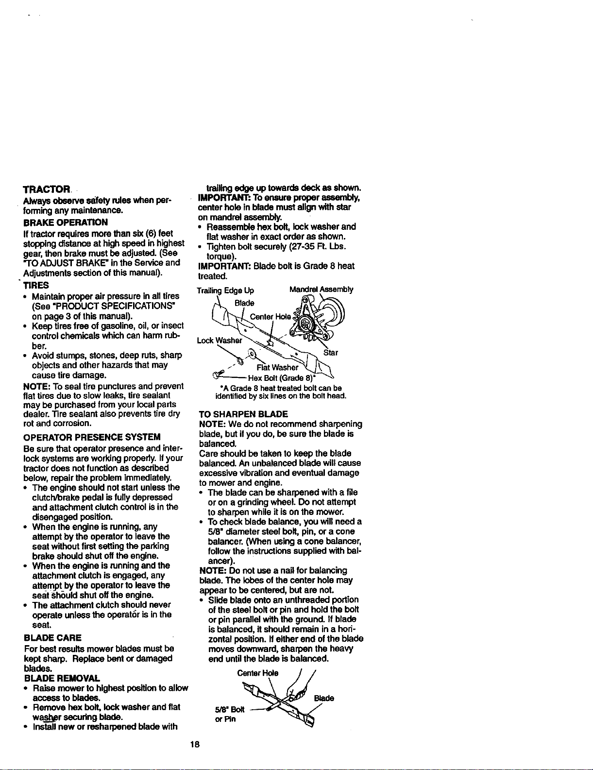
• Installnowor resharpenedbladewith
trailingedgeuptowardsdeckas shown.
IMPORTANT:Toensureproperassembly,
centerholeInblademustalignwithstar
on mandrelassembly.
• Reassemblehexbelt,lockwasherand
flatwasherinexactorderas shown.
• Tightenboltsecurely(27-35 Ft. Lbs.
torque).
IMPORTANT:BladeboltisGrade8 heat
treated.
18
I EdgeUp MandrelAssembly
Blade
CenterHole;
Lock Washel
Star
/
Hex Bolt(Grade8)*
*AGrade 8heat treatedboltcan be
identifiedby sixlinesonthebolthead.
TO SHARPEN BLADE
NOTE: We do not recommend sharpening
blade, but if you do, be sure the blade is
balanced.
Care should be taken to keep the blade
balanced. An unbalanced blade will cause
excessive vibration and eventual damage
to mower and engine.
• The blade can be sharpened with a file
or on a gdnding wheel. Do not attempt
to sharpen while it is on the mower.
• To check blade balance, you will need a
5/8" diameter steel belt, pin, or a cone
balancer. (When using a cons balancer,
follow the instructions supplied with bal-
ancer).
NOTE: Do not use a nail for balancing
blade. The lobes of the center hole may
appear to be centered, but are not.
• Slide blade onto an unthreaded portion
of the steel boltor pin and hold the bolt
or pin parallel with the ground. If blade
is balanced, it should remain in a hod-
zontai position. If either end ofthe blade
moves downward, sharpen the heavy
end untilthe blade is balanced.
BATTERY
Yourtractorhas8batterychargingsystem
whichissufficientfornormaluse.
However,periodicchargingofthebattery
withanautomotivechargerwillextendits
life.
• Keepbattery and terminals clean.
• Keep battery bolts tigM.
• Keep small vent holes open.
• Recharge at 6-10 amperes for I hour.
TO CLEAN BATTERY AND TERMINALS
Corrosion and dirt on the battery and ter-
minale can cause the battery to "leak"
power.
• Remove terminal guard.
• Disconnect BLACK battery cable first
then RED battery cable and remove
battery from tractor.
• Rinse the battery with plain water and
dry.
• Clean terminals and battery cable ends
with wire brush until bdght.
• Coat terminals with grease or petroleum
jelly.
• Reinstall battery (See "REPLACING
BATTERY" in the SERVICE AND
ADJUSTMENTS section of this manu-
al).
V-BELTS
Check V-belts for deterioration and wear
after 100 hours of operation and replace if
necessary. The belts are not adjustable.
Replace baits if they begin to slip from
wear.
TRANSAXLE COOLING
Keep transaxlefreefrombuild-upofdirt
andchaffwhichcanrestdctcooling.
ENGINE
LUBRICATION
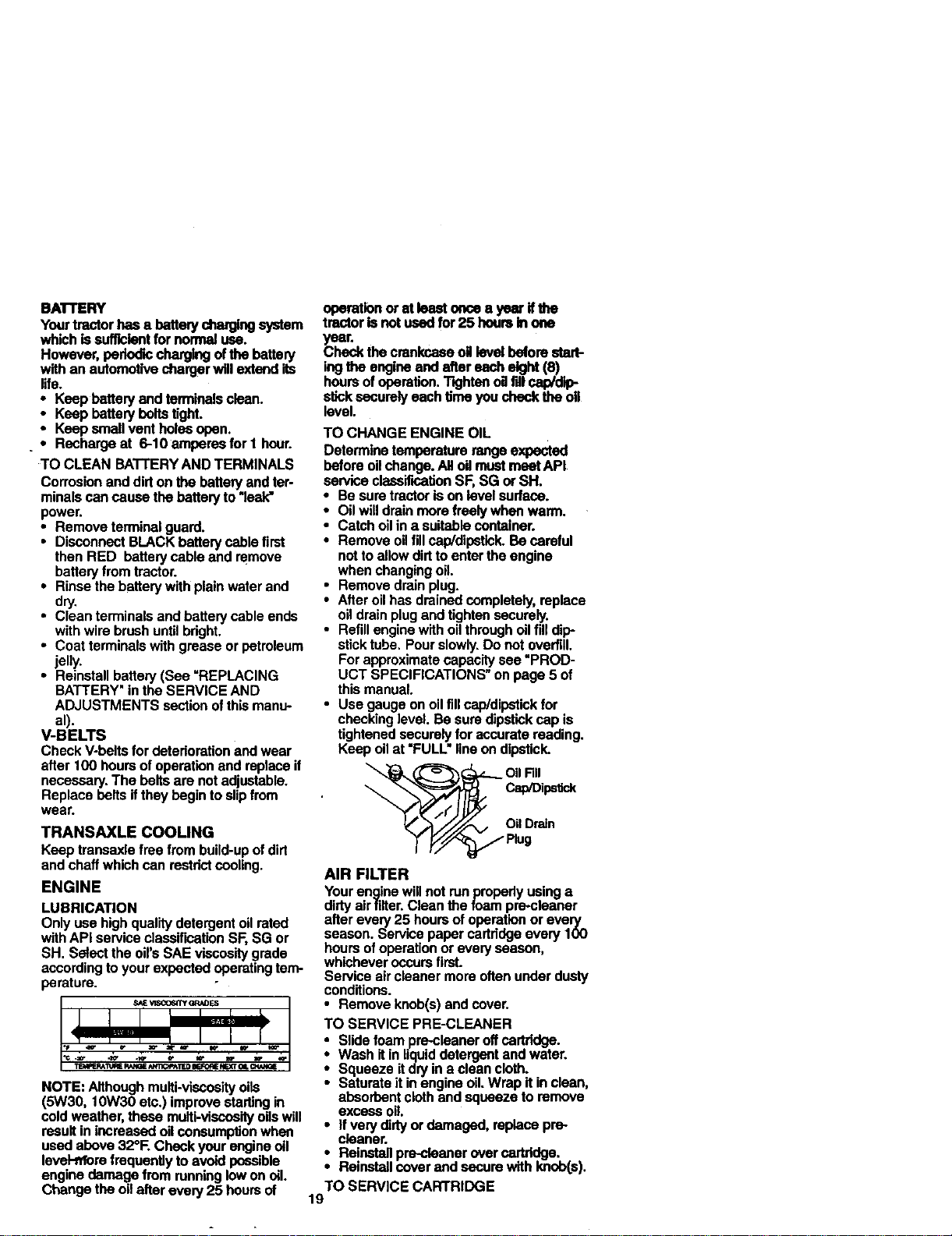
Only use high quality detergent oil rated
with API service classirmation SF, SG or
SH. Select the oil's SAE viscosity grade
according to your expected operating tem-
perature.
SAEVl,SCQ6_YGRN)ES
119&qERAI_REP.;_QE_*rrlOPAIF.DBEFORENE.x"rOILCI.L'_GE
NOTE: Although multi-vlecosity oils
(5W30, 10W30 etc.) improve starling in
cold weather, these mulU-viscosifyoilswill
result in increased oilconsumption when
used above 32°R Check your engine oil
level-hi'orefrequenUy to avoid possible
engine damage from running low on ell.
Change the oil after every 25 hoursof
operatinnor at leeetonoee yearIfthe
trantoris not usedfor25 hoursin one
year.
Checkthe crankcaseoltlevelboforestart-
ingthe engineendaftereachelgM (8)
hoursofoperation.Tightenoafilleap/dip-
sticksecurelyeachtimeyouchecktheoil
level.
TO CHANGE ENGINE OIL
Determine temperature range expected
before oil change. All oil must meet API
service classification SF, SG or SH.
• Be sure tractor is on level surface.
• Oil will drain more freely when warm.
• Catch oil in a suitable container.
• Remove oil fill cap/dipstick. Be careful
notto allow dirt to enter the engine
when changing oil.
• Remove drain plug.
• After oil has drained completely, replace
oil drain plug and tighten securely.
• Refill engine with oil thmugh oil fill dip-
stick tube. Pour slowly.Do not overfill.
For approximate capacity see "PROD-
UCT SPECIFICATIONS" on page 5 of
this manual.
• Use gauge on oil fill cap/dipstick for
checking level. Be sure dipstick cap is
tightened securely for accurate reading.
Keep oil at "FULL" line on dipstick.
OilRII
Cap/D]ps_.k
OilDrain
Plug
AIR FILTER
Your engine will not runpropedy using a
dirty airftlter. Clean the foam pre-cleaner
after every 25 hours of operation or every
season. Service paper cartridge every 100
hours of operation or every season,
whichever occurs first.
Service air cleaner more often under dusty
conditions.
• Remove knob(s) and cover.
TO SERVICE PRE-CLEANER
Slide foam pre-cleaner off cartridge.
Wash It in liquid detergent and water.
Squeeze if dry in a clean cloth.
Saturate it in engine oil. Wrap it in clean,
absorbent cloth and squeeze to remove
excess oil.
• If very dirty or damaged, replace pre-
cleaner.
• Reinstall pre-cteaner over cartridge.
Reinstall cover and secure with knob(s).
TO SERVICE CARTRIDGE
19
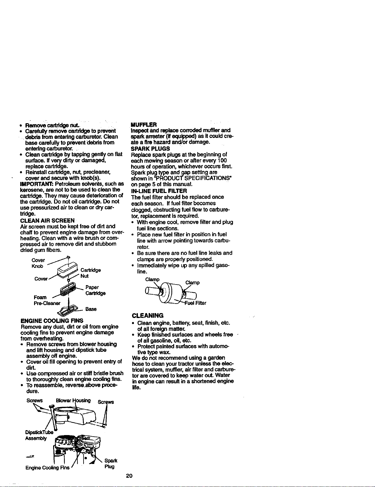
• Removecartridge nut.
• Carefully remove cartridge to prevent
debds from entedng carburetor. Clean
base carefully to prevent dabds from
entedng carburetor.
• Clean cartridge by tapping gently on fiat
surface. If very dirty or damaged,
replace cartridge.
• Reinstall cartridge, nut, precleaner,
cover and secure with knob(s).
IMPORTANT: Petroleum solvents, such as
kerosene, are not to be used to clean the
cartddge. They may cause deterioratian of
the cartridge. Do not oil cartridge. Do not
use pressurized air to clean or dry car-
tddge.
CLEAN AIR SCREEN
Air screen must be kept free of dirt and
chaff to prevent engine damage from over-
heating. Clean with a wire brush or com-
pressed air to remove dirt and stubbom
dried gum fibers.
Cover
Knob
Cartridge
Cartddge
ENGINE COOUNG RNS
Remove any dust, dirt or oil from engine
cooling fins to prevent engine damage
from overheating.
• Remove screws from blower housing
and lift housing and dipstick tube
assembly off engine.
• Cover oilfill opening to prevent entry of
dirt.
• Use compressed air or stiffbristle brush
to thoroughly clean engine cooling fins.
• To reassemble, reverseabove proce-
dure.
Sc% Blower r_
o_: T
EngineCoolingRns '_ Rug
MUFFLER
Inspect and replace corroded muffler and
spark armster (if equipped) as itcould cre-
ate a fire hazard and/or damage.
SPARK PLUGS
Replace spark plugs at the beginning of
each mowing season or after every 100
hours of operation, whichever occurs first.
Spark plugtype and gap setting are
shown in "PRODUCT SPECIFICATIONS"
on page 5 of this manual.
IN-LINE FUEL FILTER
The fuel filter should be replaced once
each season. If fuel filter becomes
clogged, obstructing fuel flow to carbure-
tor, replacement is required.
• With engine cool, remove filter and plug
fuel line sections.
• Place new fuel filter in position in fuel
line with arrow pointingtowards carbu-
retor.
• Be sure there are no fuel line leaks and
clamps are properly positioned.
• Immediately wipe up any spilled gaso-
line.
CLEANING
• Cleanengine,battery,seat,finish,etc.
ofallforeignmatter.
• Keepfinishedsurfacesandwheelsfree •
ofallgasoline,oil, etc.
• Protectpaintedsurfaceswith automo-
tivetypewax.
We do not recommendusinga garden
hosetocleanyourtractorunlessthe elec-
tricalsystem,muffler,air filterandcarbure-
torare coveredtokeepwaterout.Water
inenginecanresultin a shortenedengine
life.
2O
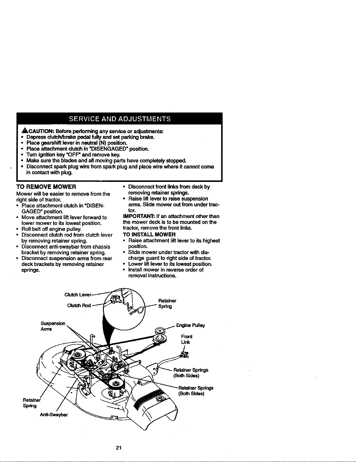
,SkCAUTION:Beforeperforminganyserviceoradjustments:.
• Depressdutch/bmkspedalfullyand setpeddng brake.
• Placegeamhiftleverin neutral(N) position.
• Placeattachmentclutchin "DISENGAGED• position.
• Turnignitionkey"OFF"and removekey.
• Makesurethebladesand allmovingpadshavecompletelystopped.
• Disconnectsparkplugwirefromsparkplugand placewire where itcannotcome
in contact withp_ug.
TO REMOVE MOWER
Mowerwillbeeasierto removefrom the
rightsideoftractor.
• Placeattachmentclutchin"DISEN-
GAGED"position.
• MoveattachmentliftleverfoeNardto
lowermowerto itslowestposition.
• Rollbeltoffenginepulley.
• Disconnectclutchrodfrom clutchlever
byremovingretainerspring.
• Disconnectanti-swaybarfrom chassis
bracketbyremovingretainerspring.
• Disconnectsusponsk:,narms from rear
deckbracketsbyremovingretainer
springs.
• Disconnect front links from deck by
removing retainer spdngs.
• Raise lift lever to raise suspension
arms. Slide mower out from under trac-
tor.
IMPORTANT: If an attachment other than
the mower deck is to be mounted on the
tractor, remove the front links.
TO INSTALL MOWER
• Raise attachment lift lever to its highest
position.
• Slide mower under tractor with dis-
charge guard to dght side of tractor.
• Lower lilt lever to its lowest position.
• Install mower in reverse order of
removal instructions.
Retainer
Front
Unk
Retainer
Spring
_vayt)ar
(BothSides)
;pdngs
(Bo_Sides)
21
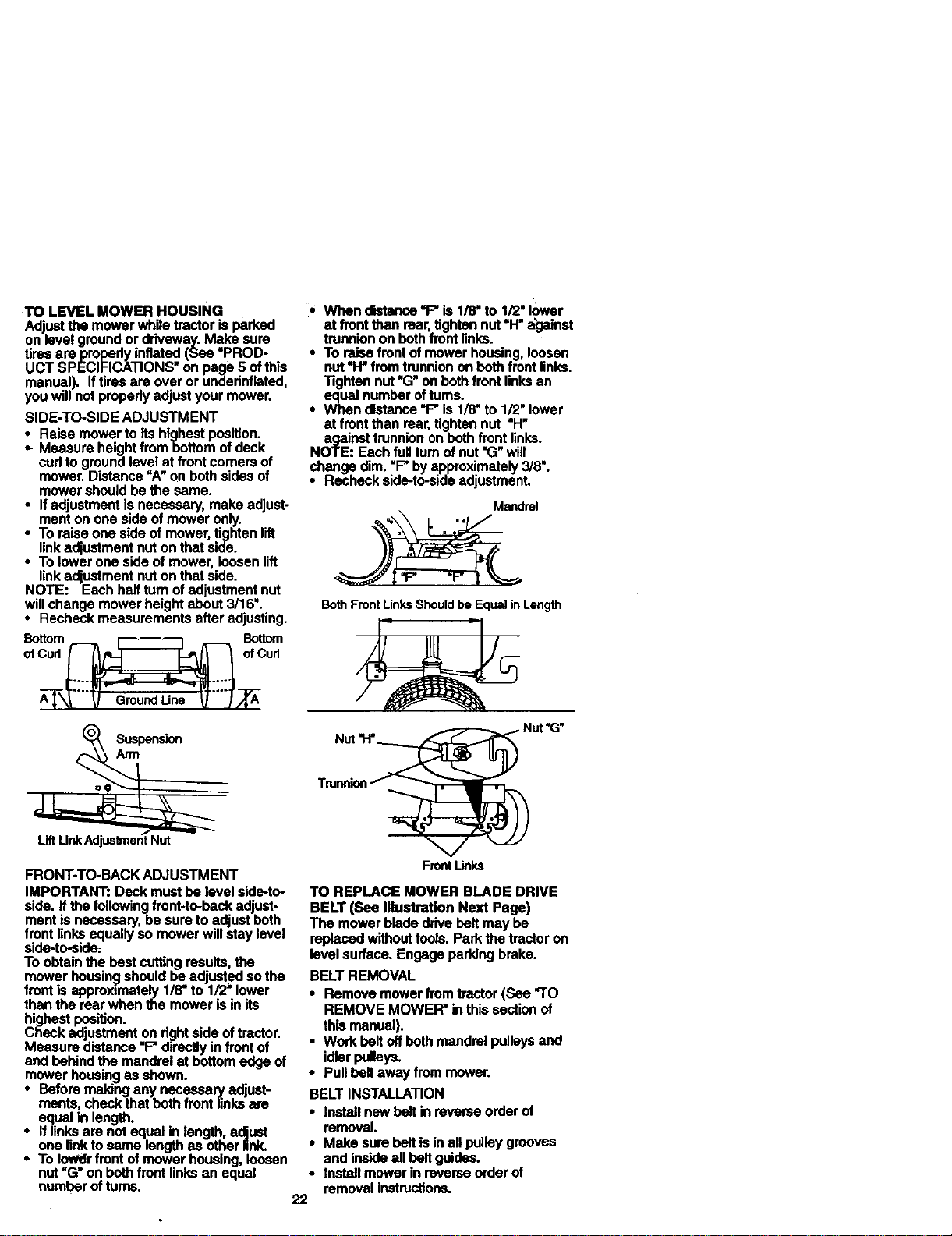
TOLEVELMOWERHOUSING
Adjustthemowerwh.iletractorisparked
onlevelgrounooruriveway.MaKesure
tiresarepmpedyinflated(See•PROD-
UCTSPECIFICATIONS"onpage5ofthis
manual).Iftiresareoverorunaednflated,
youwillnotproperlyadjustyourmower.
SIDE-TO-SIDEADJUSTMENT
• Raise mower to its highest position.
•- Measure height frombottom of deck
cud to ground level at front comers of
mower. Distance "A" on both sides of
mower should be the same.
• If adjustment is necessary, make adjust-
ment on one side of mower only.
• To raise one side of mower, lighten lift
linkadjustment nut on that side.
• To lower one side of mower, loosen lift
link adjustment nuton that side.
NOTE: Each half turn of adjustment nut
will change mower height about 3/16".
• Recheck measurements after adjusting.
o,%=;
A---_X_-""_ GroundLine _'""l_
=o_. Suspensi°n
• When distance "F" is 1/8" to 1/2" lower
• at front than rear, tighten nut "H" against
trunnion on both front links.
• To raise front of mower housing, loosen
nut "H" from trunnion on both front links.
31ghtan nut "G"on both front links an
equal number oftums.
• When distance "F" is 1/8" to 1/2" lower
at front than rear, tighten nut =H"
against trunnion on both front links.
NOTE: Each full turn of nut =G"will
change dim. =F"by approximately 3/8".
• Recheck side-to-side adjustment.
Mandrel
% .*
BothFrontLinksShouldbe Equalin Length
Nut"G"
Trunnion
FRONT-TO-BACK ADJUSTMENT
IMPORTANt': Deck must be revel side-te-
side. If the following front-to-back adjust-
ment is necessary be sure to adjust both
front links equally so mower wi I stay evel
side-to-side;.
To obtain the best cuffing results, the
mower housing should be adjusted so the
front Is approximately 1/8" to 1/2' lower
then the rear when the mower is in its
highest position.
Check adjustment on right side of tractor.
Measure d_stance"F" directly in front of
and behind the mandrel at bottom edge of
mower housing as shown.
• Before making any necesaal_ adjust°
ments, check that both front links are
equal in length.
• If links are not equal in length, adjust
one link to same length as other link.
• To Iowffr front of mower housing, loosen
nut=G"on both front links an equal
number ofturns.
Frontlinks
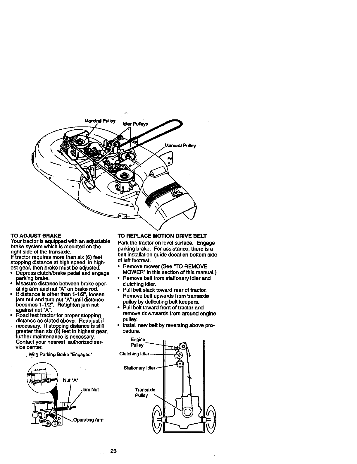
TO REPLACE MOWER BLADE DRIVE
BELT(See IllustraUonNext Page)
The mowerbladedrivebelt may be
replacedwithouttools.Parkthe tractoron
levelsurface.Engageparkingbrake.
BELTREMOVAL
• Removemowerfromtractor(See "TO
REMOVE MOWER"in thissectionof
thismanual).
• Workbeltoffbeth mandrelpulleySand
idlerpulleyS.
• Pullbelt awayfrommower.
BELTINSTALLATION
• Installnewbelt inreverseorderof
removal.
• Make surebeltisinall pulleygrooves
and insideanbelt guides.
• Installmowerinreverseorderof
removalinstructions.
22
Mandr_,PtdleyIdlerPulleys
TOADJUSTBRAKE
Yourtractorisequippedwithanadjustable
brakesystemwhichismounted on the
right side of the transaxis.
If tractor requires more than six (6) feet
stopping distance at high speed in high-
est gear, then brake must be adjusted.
• Depress clutcWbrake pedal and engage
parking brake.
• Measure distance between brake oper-
ating arm and nut "A" on brake rod.
• If distance is other than 1-1/2", loosen
jam nut and tam nut "A" untildistance
becomes 1-1/2". Retightan jam nut
against nut =A'.
• Road test tractor for proper stopping
distance as stated above. Readjust if
necessary. If stopping distance is still
greater than six (6) feet in highest gear,
further maintenance is necessary.
Contact your nearest authodzedser-
vice center.
. Wi_ ParkingBrake'Engaged"
TO REPLACE MOTION DRIVE BELT
Park the tractor on level surface. Engage
parking brake. For assistance, there is a
belt installation guide decal on bottom side
of left footrest.
• Remove mower (See "TO REMOVE
MOWER" in this section of this manual.)
• Remove belt from stationary idler and
clutching idler.
• Pull belt slack toward rear of tractor.
Remove belt upwards from transaxle
pulley by deflecting belt keepers.
• Pull belt toward front of tractor and
remove downwards from around engine
pulley.
• install new be_tby reversing above pro-
cedure.
Engine
Pulley
ClutchingIdler_
_ Nut "A" StatioParytdter_
---- ' i
23
TO ADJUST STEERING WHEEL ALIGN-
MENT
If staedngwbeel creasbars are not hori-
zontal (le]t to right)when wheels are peei-
tioned straight forward, remove steenng
wheel and reassemble per instrustionsin
the Assembly section of this manual.
FRONT WHEEL TOE-IN/CAMBER
The front wheel toe-in and camber are not
ad ustable on your tractor. If damage has
occurred to affect the front whoa toe- n or
camber, contact your nearest authorized
service center.
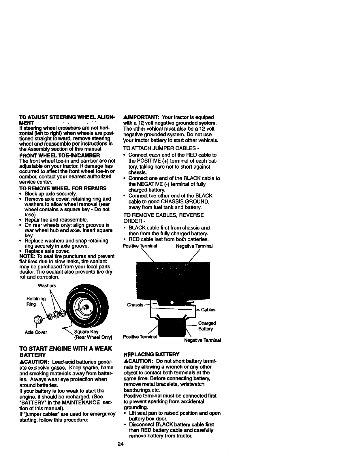
TO REMOVE WHEEL FOR REPAIRS
* Block up axle securely.
Remove axle cover, retaining ring and
washers to allow wheel removal (rear
wheel contains a square key - Do not
lose).
• Repair tire ano reassemble.
• On rear wheels only: align grooves in
rear wheel hub and axle. Insert square
key.
• Replace washers and snap retaining
ringsecurely in axle groove.
• Replace axle cover.
NOTE: To seal tire punctures and prevent
flat tires due to slow teaks, tire sealant
may bepurchased from your local parts
dealer. _re sealant also prevents lire dry
rot and corrosion.
&IMPORTANT: Your tractor Is equiped
with a 12 volt negative grounded system.
The other vehical must also be a 12 volt
negative grounded system. Do not use
your tractor battery to start other vshicals.
TO A'I-I'ACH JUMPER CABLES -
• Connect each end of the RED cable to
the POSITIVE (+) terminal of each bat-
tery, taking care not to short against
chassis.
• Connect one end of the BLACK cable to
the NEGATIVE (-) terminal of fully
charged battery.
• Connect the other end of the BLACK
cable to good CHASSIS GROUND,
away from fuel tank and battery.
TO REMOVE CABLES, REVERSE
ORDER -
• BLACK cable first from chassis and
then from the fully charged battery.
• RED cable last from both batteries.
PositiveTerminal NegativeTerminal
RetainiWn_h_ A
(RearWheel Only)
TO START ENGINE WITH A WEAK
BATTERY
&CAUTION: Lead-acid batteries goner-
ate explosive gases. Keep sparks, flame
and smoking matadals away from batter-
lss. Always wear eye protection when
around batteries.
If your battery istoo weak to start the
engine, it should be recharged. (See
"BATTERY" in the MAINTENANCE sec-
tion of this manual).
If "jumper cables" are used for emergency
starting, follow this procedure:
PositiveTerminal
Battery
NegativeTerminal
REPLACING BA'n'ERY
&CAUTION: Do not short battery termi-
nals by allowing a wrench or any other
object to contact both terminals at the
same time. Before connecting battery,
remove metal bracelets, wristwatch
bands,rings,etc.
Poaltive terminal must be connected first
to prevent epaddng from accidental
grounding.
• Liftseat pan to raised position and open
battery box door.
• Disconnect BLACK battery cable first
then RED battery cable and carefully
remove battery from tractor.
24
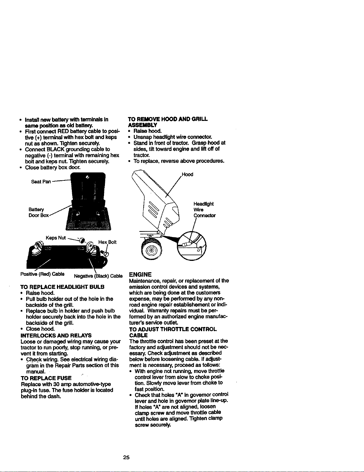
• Inatailnewhettery withterminaisin
seine positionasoldbattery.
• FirstconnectRED batterycabletoposi-
tive (+)terminalwithhexboltand keps
nutas shown."nghtansecurely.
• ConnectBLACKgroundingcableto
negative(-) terminalwithremaininghe:<
beltand kepsnut."13ghtansecurely.
• Closebatterybox door.
Hex Bolt
TO REMOVE HOOD AND GRILL
ASSEMBLY
• Raisehood.
• Unsnapheadlightwireconnector.
• Standinfrontoftmutor.Grasphoodat
sides,tilttowardengineand liftoffof
tmctor.
• To replace,reverseaboveprocedures.
Headlight
r
Positive (Red) Cable Negative (Black) Cable
TO REPLACE HEADLIGHT BULB
• Raise hood.
• Pull bulb holder out of the hole in the
backside of the grill.
• Replace bulb in holder and push bulb
holder securely back intothe hole in the
backside ofthe gdll.
• Close hood.
INTERLOCKS AND RELAYS
Loose or damaged widng may cause your
tractor to run poorly, stop running, or pre-
vent it from starting.
• _Checkwiring. See electrical wldng dia-
gram in the Repair Parts section of this
manual.
TO REPLACE FUSE
Replace with 30 amp automotive-type
plug-in fuse. The fuse holder is located
behind the dash.
ENGINE
Maintenance, repair, or replacement of the
emission control devicse and systems,
which are being done at the customers
expense, may be performed by any non-
road engine repair ostablishement or indi-
vidual. Warranty repairs must be per-
formed by an authorized engine manufac-
turer's service outleL
TO ADJUST THROTTLE CONTROL
CABLE
The throttle control has been preset at the
factory and adjustment should not be nec-
essary. Check adjustment as deecdbed
below before loosening cable. Ifadjust-
ment is necessary, proceed as follows:
• With engine not running, move throttle
control lever from slow to choke posi-
tion. Slowly move lever from choke to
fast position.
• Check that holes "A• in govemor control
lever and hole in governor plate line-up.
If holes "A"am not aligned, loosen
clamp screw and move throttle cable
until holes are aligned. Tighten clamp
screw S(_'U roly,
25
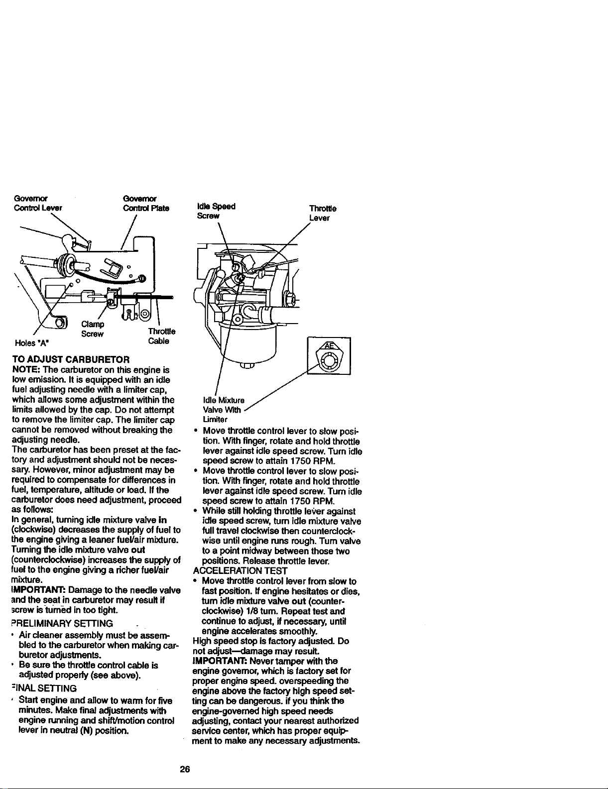
Governor Qovernor
CorrbolLever ControlPlate
Clamp
Screw Throttle
Holes"A" Cable
TO ADJUST CARBURETOR
NOTE: The carburetor on this engine is
low emission. It is equipped with an idle
fuel adjusting needle with a lirnitercap,
which allows some adjustment within the
limits allowed by the cap. Do not attempt
to remove the limiter cap. The limitar cap
cannot be removed without breaking the
adjusting needle.
The carburetor has been preset at the fac-
tory and adjustment should not be neces-
sary. However, minor adjustment may be
required to compensate for differences in
fuel, temperature, altitude or load. Ifthe
carburetor does need adjustment, proceed
as follows:
In general, taming idle mixture valve In
(clockwise) decreases the supply of fuel to
the engine giving a leaner fuel/air mixture.
Turning the idle mixture valve out
(counterclockwise) increases the supply of
fuel to the engine giving a dcher fuel/air
mixture.
IMPORTANT: Damage to the needle valve
and the seat in carburetor may result if
screw is-turned in too tight.
PRELIMINARY SETTING
• Air cleaner assembly must be assem-
bled to the carburetor when maldng car-
buretor adjustments.
• Be sure the throttle control cable is
acljustedproperly (see above).
:INAL SETTING
• Start engine and allow to warm for five
minutes. Make final adjustments with
engine running and shift/motion control
lever in neutral (N) position.
IdleSpeed Throltle
Screw Lever
Um_r
• Move throttle control lever to slow posi-
tion. With finger, rotate and hold throttle
lever against idle speed screw. Turn idle
speed screw to attain 1750 RPM.
• Move throttle control lever to slow posi-
tion. With finger, rotate and hold throttle
lever against idle speed screw. Turn idle
speed screw to attain 1750 RPM.
• While still holding throttle lever against
idle speed screw, rum idle mixture valve
full travel clockwise then counterclock-
wise until engine runs rough. Turn valve
to a point midway between those two
positions. Release throttle lever.
ACCELERATION TEST
• Move throttle control lever from slow to
fast position. If engine hesitates or dies,
tum idle mixture valve out (counter-
clockwise) 1/8 tum. Repeat test and
continue to adjust, if necessary, until
engine accelerates smoothly.
High speed stop isfactory adjusted. Do
not adjust--damage may result.
IMPORTANT:. Never tamper with the
engine govemor, which is factory set for
proper engine speed, overapeeding the
engine above the factory high speed set-
ting can be dangerous, if you think the
engine-govemed high speed needs
adjusting, contact your nearest authorized
service center, which has proper equip-
ment to make any necessary adjustments.
26
Immed_tehj preparey_ tractorforstor-
ageat the endoftheseasonor ifthe trac-
tor willnotbe usedfor 30 daysor more.
ACAUTION: Never storethetractorwith
_hasolineinthe tankinsidea building
ere fumesmay reachan openflame or
spark.Allowthe engineto coolbefore
storinginanyenclosure.
TRACTOR
Remove mowerfromtractorforwinter
storage.Thiswillallowyoutoclean if thor-
oughly.Removeall dirt,grease,leaves,
etc. Storein a clean,dryarea.
• Clean entiretractor(See "CLEANING"
inthe Maintenancesection ofthis man-
Ual).
• Inspectand replacebelts,ifnecessary
(See beltreplacementinstructionsinthe
ServiceandAdjustmentssectionofthis
manual).
• Lubricateas showninthe Maintenance
sectionofthismanual.
• Besure thatall nuts,boltsand screws
are securelyfastened.Inspectmoving
partsfor damage,breakageand wear.
Replaceifnecessary.
• Touchup all rustedorchipped.paintsur-
faces;sandlightlybeforepainting.
BATTERY
* Fullychargethe batteryforstorage.
Aftera periodoftime instorage,battery
may requirerecharging.
• To helppreventcorros=onand power
leakageduringlongperiodsofstorage,
batterycablesshouldbe disconnected
andbatteryelsened thoroughly (see
"TO CLEAN BATTERYAND TERMI-
NALS"inthe Maintenancesectionof
this manual).
• Aftercleaning,leavec_blesdisconnect*
ed andplace cableswheretheycannot
come:in-contactwithbatteryterminals.
• If batteryisremovedfrom tractorfor
storage,do notstorebattepjdirectly on
concreteordampsurfaces.
FUELSYSTEM
IMPORTANT:Itis importanttoprevent
gumdepositsfromforminginessential
fuel systemports suchas carburetor,fuel
filler,fuelhose,ortankduringstorage.
Also,experienceindicatesthatalcohol
blendedfuels(calledgacoholor using
ethanolormethanol)canattract moisture
whichleadstoseparationandformation of
acidsduringstorage.Acidicgascandam-
agethefuelsystemofan enginewhilein
storage.
Drainthefuel tank.
Startthe engineand letif rununtilthe
_fuel lines areempty.
andcarburetor
Neveruseengineor carburetorcleaner
productsin thefueltankor permanent
damagemayoccur.
• Usefreshfuel nextseason.
NOTE: Fuelstabi_zeris an acceptable
alternative inminimizingtheformationof
fuel gumdepositsdudngstorage.Add sta-
bilizertogasolineinfuel tank orstorage
container.A_aye fol|owthe mix ratio
foundon stabilizercontainer.Runengine
at least10 minutesafter addingstabllizer
toallowthestabilizertoreachthe carbure-
tor.Donotdrainthe_as tankand carbure-
torif usingfuel stabihzer.
ENGINE OIL
Drainoil(withenginewa=rrn_and replace
withcleanengineell. (See ENGINE"in
the Maintenancesectionofthismanual).
CYLINDER(S)
Removesparkplug(s).
Pourone ounceofoilthroughspark
plug hole(s)intocylinder(s).
•Tum ignitionkeyto=START"position for
a few seconds todistributeoil.
• Replacewithnewsparkplug(s).
OTHER
• Donotstoregasolinefrom oneseason
toanother.
• Replaceyourgasolinecanifitstartsto
rust.Rustand/ordirtinyourgasoline
willcauseproblems.
• II possible, store yourtractorindoors
andcoveritto giveprotectionfromdust
anddirL
• Coveryourtractorwitha suitablepro-
tac_vecoverthatdoesnotretainmdis-
lure.Do notuseplastic.Plasticcannot
breathe,which allowscondensationto
formandcauseyourtractorto rust.
IMPORTANT: Nevercovertractorwhile
engineand exhaustareasarestillwarm.
27
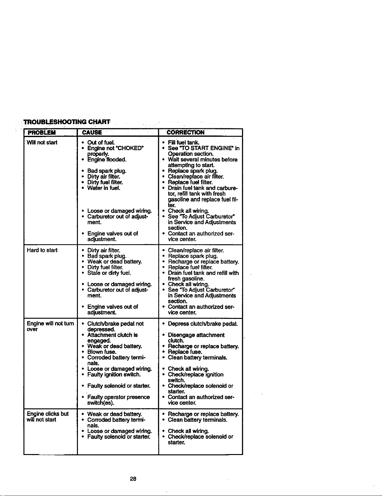
TROUBLESHOOTING
PROBLEM
Will not start
Hard to stad
Engine will not turn
over
Engine clicks but
will not start
CHART
CAUSE •
• Out of fuel.
• Engine not "CHOKED"
repel.
• _ngine flooded.
i Badsparkplug.
Dirtyair filter.
Dirtyfuel filter,
Waterinfuel.
• Loose or damaged widng.
Carburetor out of adjust-
ment.
• Enginevalvesoutof
adjustment.
• Dirty air filter.
Bad spark plug.
• Weak or dead battery.
• Dirty fuel filter.
Stale or didy fuel.
• Loose or damaged widng.
Carburetor out of adjust-
ment,
• Enginevalvesoutof
adjustment.
• ClutcWbmke pedal not
depressed.
• Attachment clutch is
engaged.
• Weak or dead battery.
• Blown fuse.
• Corroded battery termi-
nals,
Loose or damaged widng.
Faulty ignitionswitch,
• Faulty solenoid or starter.
• Faulty operator presence
switch(ea).
• Weak or dead battery.
• Corroded battery termi-
nals.
" Loose or damaged widng.
Faulty solenoid or starter.
CORRECTION
• Fillfuel tank.
• Sea "TO START ENGINE"in
Operationsection.
• Waltseveral minutes before
attemptingtostart.
• Replace sparkplug.
Clean/re)laceair filter.
: Replace fuelfilter.
Drainfuel tankandcarbure-
tor,refilltank withfresh
gasolineand replacefuelfil-
tar.
• Checkallwidng.
See "ToAdjustCarburetor"
in ServiceandAdjustments
section.
• Contactanauthorizedser-
vicecenter.
• Clean/replace air filter.
-..Replace spark plug.
Recharge or replace battery.
Replace fuel filter.
Drain fuel tank and refillwith
fresh gasoline.
• Check all widng.
See "ToAdjust Carburetor"
in Service and Adjustments
section.
• Contact an authorized ser-
vice center.
• Depreseclutch/brakepedal.
• Disengage attachment
clutch.
Recharge or replace battery,
Replace fuse.
Clean battery terminals.
: Check all wiring.
ChecPJreplace ignltion
switch.
• Chack/replace solenoid or
starter
• Contact an authodzed ser
vice center.
• Rechargeor replacebattery.
• Cleanbatteryterminals.
• Check all wiring.
Check/replace solenoid or
starter.
28
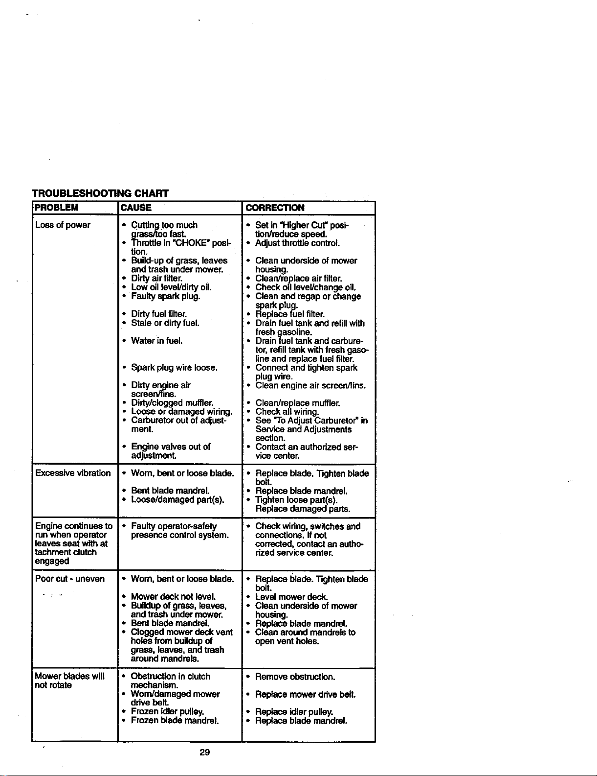
TROUBLESHOOTING CHART
PROBLEM CAUSE
Lossofpower • Cuffingtoo much
grassJtoofast.
Throttlein"CHOKE"poai-
tioo.
Excessive vibration
Enginecontinuesto
runwhenoperator
leavesseatwithat
tachrnantclutch
engaged
Poorcut- uneven
Mowerbladeswill
notrotate
• Build-upofgrass,leaves
andtrashundermower.
: Dirtyairfilter.
Lowoillevel/dirtyoil.
• Faultysparkplug.
• Dirtyfuelfilter.
• Staleordirtyfuel.
• Water infuel.
• Sparkplugwire loose.
• Dirtyen,_gineair
screer,mns.
• Dirty/cloggedmuffler.
Looseor damagedwiring.
Carburetoroutofadjust-
ment.
• Enginevalvesoutof
adjustment.
• Wom, bentor looseblade.
• Bentblademandrel.
• Loose/damagedpart(s).
• Faultyoparator-safety
presencecontrolsystem.
• Worn,bent or looseblade.
• Mowerdecknotlevel.
• Buildupofgrass,leaves,
and trashundermower.
• Bent blademandrel.
• Cloggedmowerdeckvent
holesfrombuildupof
grass,leaves,and trash
aroundmandrels.
I. Obstructioninclutch
!• mechanism.
Worn/damagedmower
drivebell
• Frozanidlerpulley.
• Frozenblademandrel.
CORRECTION
• Setin "HigherCut"pcei-
tion/reducespeed.
• Adjustthrottlecontrol.
• Cleanundersideofmower
housing.
i Clesn/m..placeair filter.
Checkodlevel/changeoil.
Cleanand regapor change
sparkplug.
; Replacefuelfilter.
Drainfuel tankand refillwith
freshgasoline.
• Drainfuel tank andcarbure-
tor,refilltankwithfreshgaso-
lineand replacefuel filter.
• Connectandtightenspark
plugwire.
• Cleanengineair screen/fins.
i Clean/replace muffler.
Check all wiring.
See "ToAdjust Carburetor" in
Service and Adjustments
section.
• Contact an authorized ser-
vice center.
• Replaceblade._ghten blade
boll
• Replaceblademandrel.
• "13ghtenloosepart(s).
Replacedamagedpads.
• Checkwidng,switchesand
connections.Ifnot
corrected, contactan autho-
rizedservicecenter.
• ReplaceI_lade."Rghtanblade
bolt.
• Levelmowerdeck.
• Cleanundersideofmower
housing.
• Replaceblade rnandrel.
Cleanaroundmandrelsto
openventholes.
• Remove obstruction.
• Replace mower drive belt.
• Replace idler pulley.
Replace blade mandrel.
29
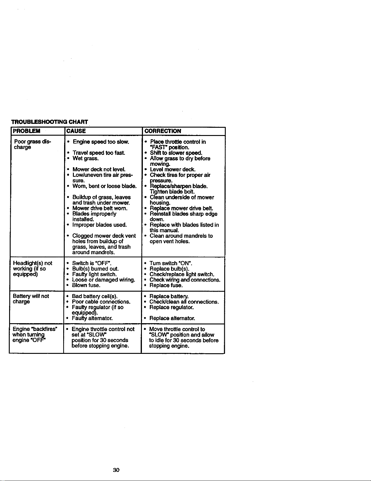
TROUBLESHOOTING CHART
CAUSEPROBLEM
Poorgrassdis-
charge
• Enginespeedtooslow.
• Travelspeedtoofest.
• Wet grass.
* Mower deck not level.
• Low/uneven tire air pres-
sure.
•Wom, bent or loose blade.
• Buildup of grass, leaves
and trash under mower.
• Mower drive belt worn.
• Blades improperly
installed.
• Improper blades used.
• Cloggedmowerdeckvent
holesfrombuildupof
grass,leaves,andtrash
aroundmandrels.
CORRECTION
• Placethrottlecontrolin
"FAST"position.
* Shifttoslowerspeed.
Allew,grasstodrybefore
mowmg.
• Level mowerdeck.
• Checktiresfor properair
res_3ure.
_ace/sharpen blade.
Tightenbladebolt.
Cleanundersideofmower
housing,
• Replacemowerddvebelt.
Reinstallbladessharpedge
down.
• Replacewithbladeslistedin
thismanual.
• Cleanaround mandrelsto
openventholes.
Headlight(s) not • Switch is"OFF'. * Tum switch "ON'.
woddng (if so • 3ulb(s) burned out. * Replace bulb(s).
equipped) • :auity lightswitch. _ Check/replace light switch.
• .oose or damaged widng. Check widng andconnections.
• Blown fuse. • Replace fuse.
Battery will not Bad battery cell(s). Replace battery.
charge ,*
Poor cable connections. Check/clean all connections.
_ Fau.ltyregulator (if so i• Replace regulator.
equippeo).
Faulty altemator. • Replace alternator.
Engine "backfires" * Engine throttle control not • Move throttlecontrol to
when tuming set at "SLOW" "SLOW" position and allow
engine "OFF" position for 30 seconds to idle for 30 seconds before
before stopping engine, stopping engine.
30

SCHEMATIC
TRACTOR - - MODEL NUMBER 917.270613
BATTERY
RED
AMMETER
(OPTIONAL)
r_< )G LI
HEADLIGHTS
IGNITIONswrrcH
YOUR TRACTOR IS
EQUIPPED WITH A SPECIAL
ALTERNATOR SYSTEM.
THE UGHTS ARE NOT
CONNEC'I1ED TO THE
BATTERY, BUT HAVE THEIR
OWN ELECTRICAL SOURCE.
BECAUSE OF THIS, THE
BRIGHTNESS OF THE LIGHTS
WILL CHANGE WITH ENGINE
SPEED. AT IDLE THE UGHTS _ 0 /-}
WILL DIM. AS THE ENGINE IS NON-REMOVABLE REMOVABLE
SPEEDED UP, THE UGHTS CONNECTIONS CONNECTIONS
WILL BECOME THEIR BRIGHTEST.
WIRING INSULATED CLIPS
NOTE: IF WIRING INSULATED CLIPS WERE REMOVED FOR
SERVICING OF UNIT, THEY SHOULD BE REPLACED TO
PROPERLY SECURE YOUR WIRING.
31
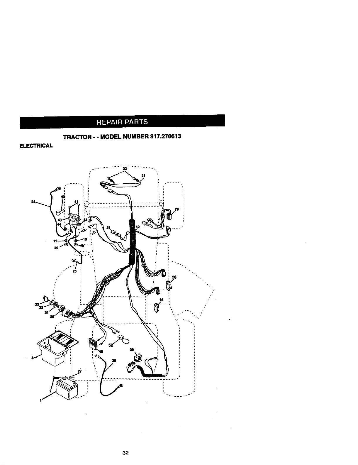
TRACTOR-- MODEL NUMBER 917.270613
ELECTRICAL
21
25
pr
+l .
32
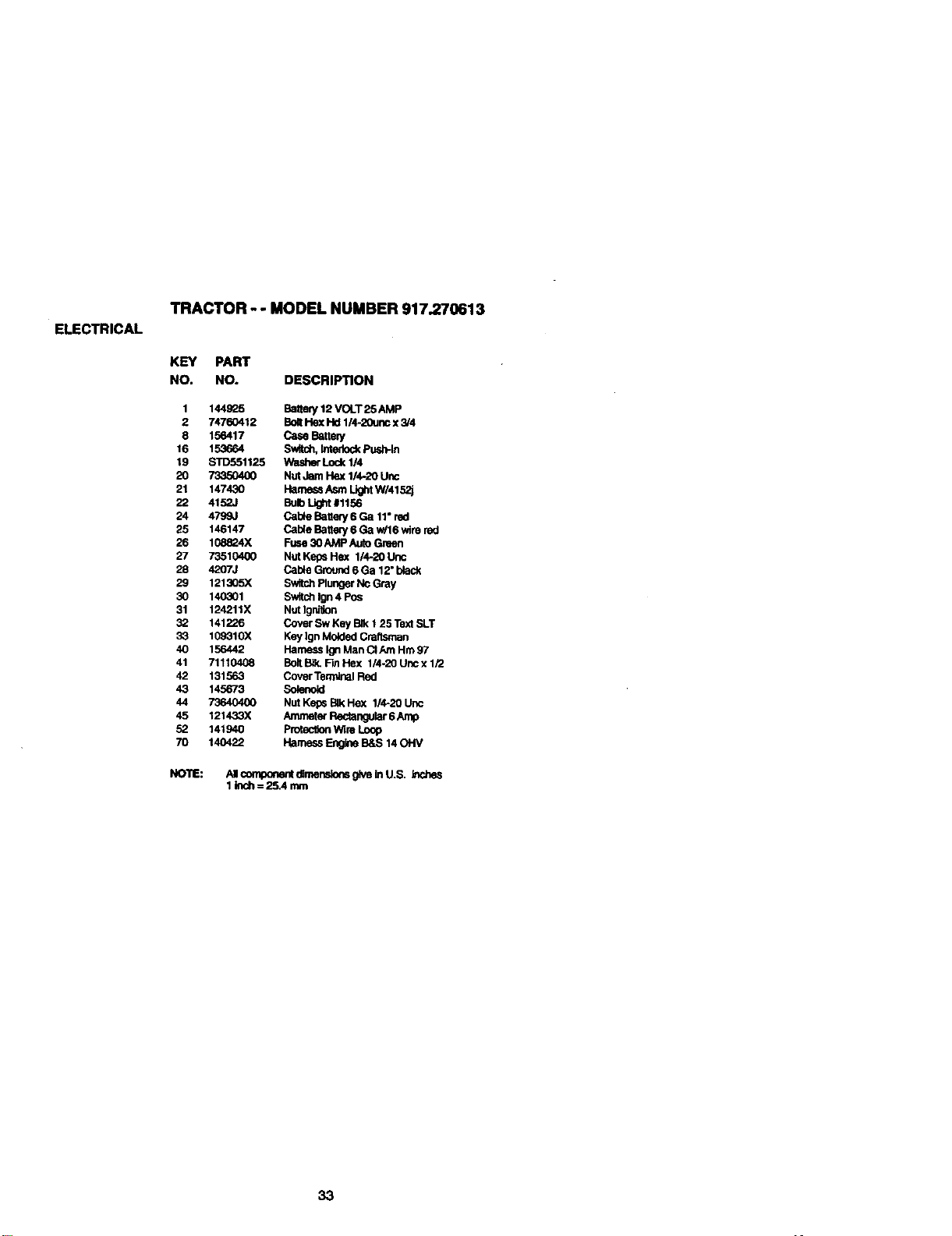
ELECTRICAL
TRACTOR - - MODEL NUMBER 917.270613
KEY PART
NO. NO. DESCRIPTION
1
2
8
16
19
20
21
22
24
25
26
27
28
29
3O
31
32
33
4O
41
42
43
44
45
52
70
144925 Bakery 12 VOLT 25 AMP
74760412 Boll Hex Hd 1/4-20unc x 3/4
156417 Case BatteP/
153664 Switch, Intedock Push-kl
STD551125 Washer Lock 1/4
73350400 Nut Jam Hex 1/4-20 uric
147430 Harness Asm Ught W/4152j
4152J Bulb Light #1156
4799,1 Cable Banefy 6 Ga 11" red
146147 Cable Battery 6 Ga w/16 wire red
108824X Fuse 30 AMP Auto Green
73510400 Nut Keps Hex 1/4-20 Unc
4207J Cable Ground 6 Ga 12" black
121305X Switch Plunger Nc Gray
140301 Switch Ign 4 Pos
124211X Nut IgnNon
141226 Cover Sw Key BJk1 25 Text SLT
109310X Key Ign Molded Craftsman
156442 Harness Ign Man CI Am Hm 97
71110408 Bolt B_ Fm Hex 1/4-20 Unc x 1/2
131563 Cover Tem,Jnal Red
145673 Solenoid
73640400 Nut Keps Blk Hex 1/4-20 Uric
121433X Ammeter Rec_ngular 6 Amp
141940 Protection Wire Loop
140422 Harness Er_e B&S 14 OHV
NOTE: AI compone__rne_,_s giveinU.S.
1Inch= 25.4 mm
33
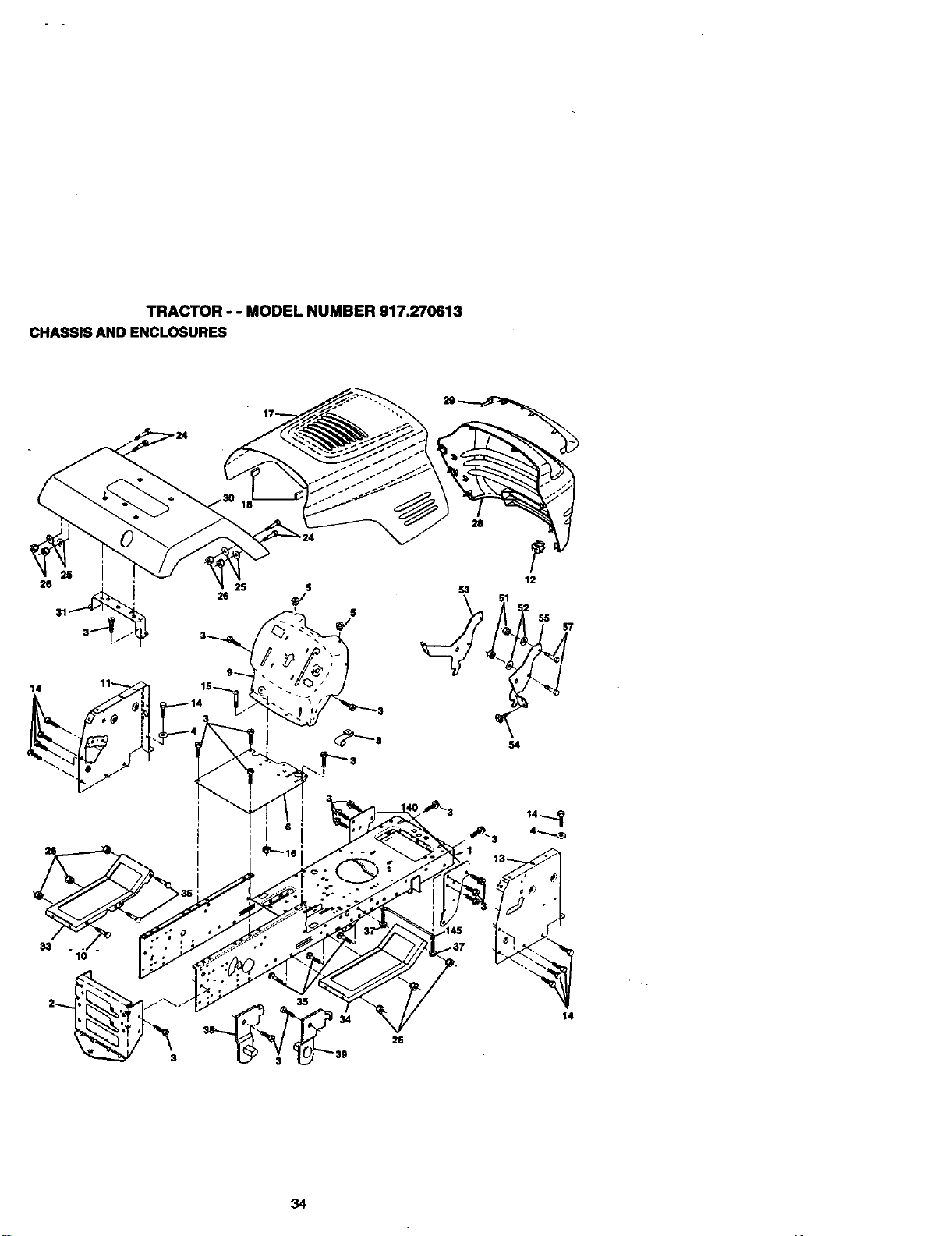
TRACTOR-- MODELNUMBER917.270613
CHASSISANDENCLOSURES
28
12
55
14 11 115_
34

TRACTOR " - MODEL NUMBER 917.270613
CHASSIS AND ENCLOSURES
KEY PART
NO. NO. DESCRIPTION
I 160393 Chassis h._emUy
2 140356 Drawt_"
3 17490612 Screw. 131d,Roll 3/8-16 x 3/4
4 STD551025 Washer" 13/32 x 3/4 x 16 Gauge
5 155272 Bumper Hood/De._
6 155924X012 Saddle
8 155138 Clip Retairmr SlJde-Oo
9 161935X013 Dash
10 STD533710 Bolt, Carriage 3/8-16 x 3/4
11 155927 Panel, Dash, LH.
12 145660 Clip "nnnerman Grille PA.
13 135354X010 Panel, Asm. SLKSCR Dash R.H.
14 17490608 Screw Thdrol 3/8-16 x 1/2
15 74180512 Screw. Machine, Truss Hea_ 5/16-18 UNC x 3/4
16 STD541431 Nut
17 144983)(558 Hood Assembly
18 126938X Bumper Hood
24 STD523710 Bolt
25 19131312 Washer 13132 x 13/16 x 12 Gauge
26 STD541437 Nut
28 145135X558 Grille wiClip_;MS-558
29 155217X599 Lens, Gdlle
30 157584X535 Fender
31 136619 Bracket, Fender Support
33 145244X558 Footrest, Lit.
34 145243X558 Footrest, I_H.
35 STD533707 Bo_t
37 1749(_ Screw Tl_lrol 5/16-18 x 1/2 TYT
38 139886 Pivut Bracket Assemb_, LH.
39 139887 Pi_Ot Bracket Assembly, R.H.
51 73800400 Nut Lock w/lnsert 114-20 UNC
52 19091416 Washm" 9/32 x 7/8 x 16 Ge.
53 145201 Bracket Gdle Pfcko_ LH
54 161464 Scow Hex WSHD 8-18 x 7/8
55 14520_ Bracket Gdlle Picboff P_H
57 STD522507 Bolt, Fin Hex 1/4-20 UNC x .75
140 158419 Brackst Flont Su_
145 156524 Rod Pi_ot C_
- - s479J Plug, Button
NO'rF_: AI _ drnenslo_ giveinU.S.
1klCh= 25.4 mm
35
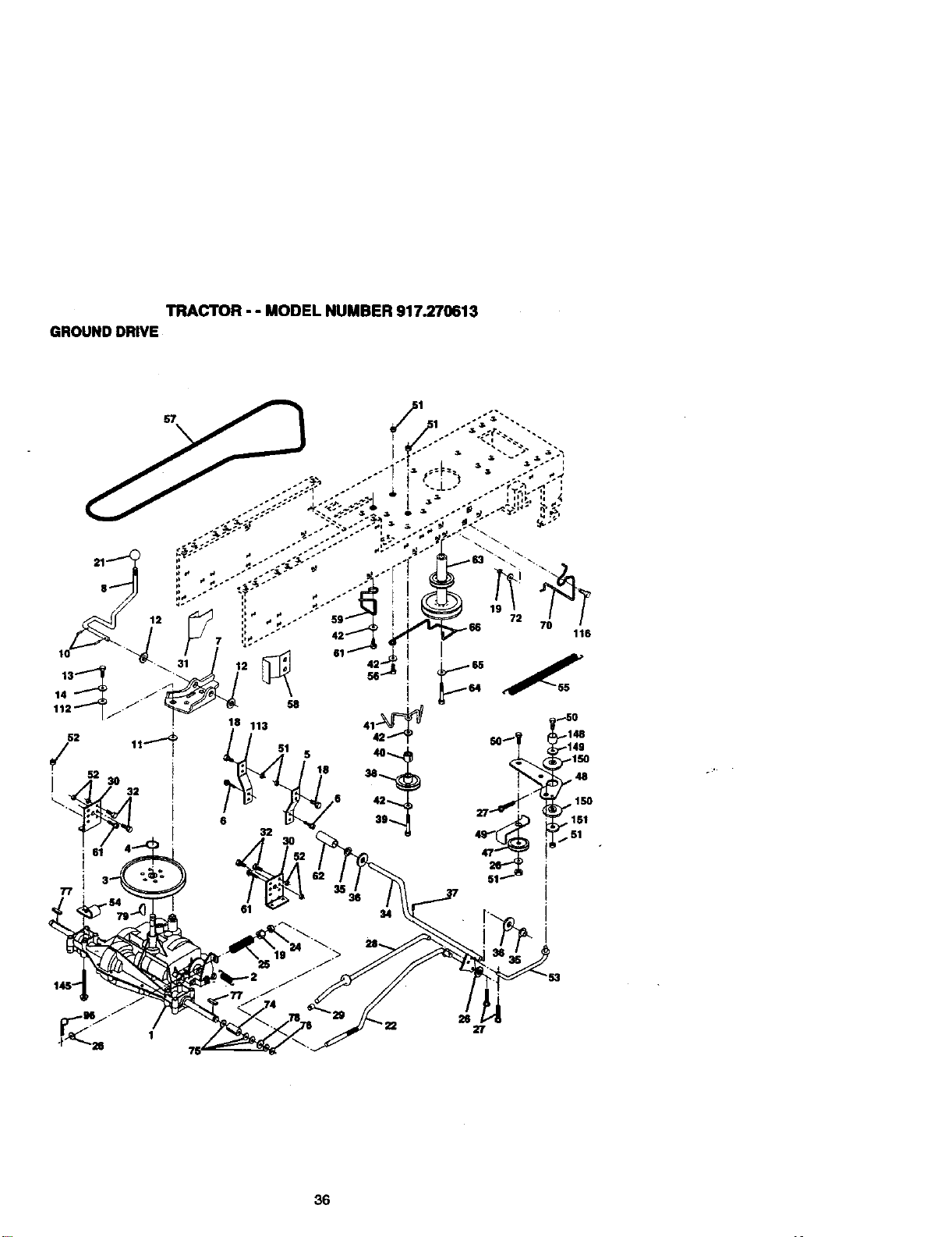
TRACTOR-- MODELNUMBER917.270613
GROUNDDRIVE
36
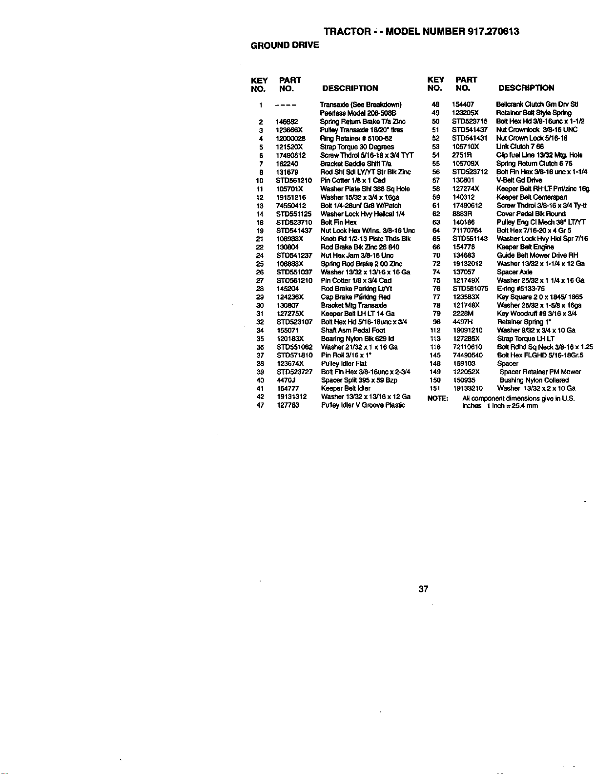
TRACTOR - - MODEL NUMBER 917.270613
GROUND DRIVE
KEY PART KEY PART
NO. NO. DESCRIPTION NO. NO. DESCRIPTION
2
3
4
5
6
7
8
10
11
12
13
14
18
19
21
22
24
25
26
27
28
29
3O
31
32
34
35
36
37
38
39
4O
41
42
47
.... Transaxle (See Breakdown) 48 154407 Belk:mnk Clut.ch Grn Dry Stl
Peedess Model 206-508B 49 123205X Retaber BOlt Slyle Sp_
146682 Sp_ Retain Brake T/a 2]nc 50 STD523715 Bolt Hex Hd 3_-16un¢ x 1.1/2
123666X Pultay T_ 18/20" tires 51 $1I)541437 Nut Crownlock 3/8-16 UNC
12000028 Ring Retainer # 5106-62 52 STD541431 Nut Crown Lock 5/16-18
121520X Strap Torque 3ODngrees 53 105710X Link Clutch 7 66
17490512 Screw "n_lrol 5/16-18 x 3/4 TYT 54 2751R Clip fuel Line 13/32 M_g. Hole
162240 Bracket Saddle Shift Tia 55 105709X Spdng Return Clutch 6 75
131679 Rod Shf Sdl Ly/YT Str BIk Zinc 56 STD523712 Bolt Rn Hex 3/8-16 unc x 1-1/4
$10561210 Pin Coner 1/8 x I Cad 57 130801 V-Belt Gd Ddve
10o"701X Washer Plata Shf 388 Sq Hole 58 127274X Keeper BO_ RH LT Pntizinc 169
19151216 Washer 15/32 x 5/4 x 169a 59 140312 Keeper Belt Cetltempan
74550412 Bolt 1/4-28unf Gr8 W/Patch 61 17490612 Screw Thdrd 3/6-16 x 3/4 Ty-tt
STD551125 Washer Lock f'Iw Helical 1/4 62 8883R Cover Pedal Btk Round
STD523710 Bolt Fin Hex 63 140186 Pulley Eng CI Mech 38° LT/YT
STD541437 NUt Lock Hex W/Ins. 3/6-16 Uric 64 71170764 Bolt Hex 7116-3O x 4 Gr 5
1Q6933X Knob Rd 1/2-13 PtstcThds BIk 65 STD551143 Washe¢ Lock Hvy Hid Spr 7/16
130804 Rod _.e BIk Zinc 26 840 66 154778 Keeper Belt Engine
STD541237 NUt Hex Jam 3i8-16 Unc 70 134683 Guide Belt Mowe¢ Ddve RH
106888X Spring Rod Brake 2 00 Zinc 72 19132012 Washer 13/32 x 1.1/4 x 12 Ga
STD551037 Washer 13/32 x 13/16 x 16 Ga 74 137057 SpacerAxta
ST0561210 PinCottarli8x5/4Cad 75 121749X Washer25/32.x1 l/4x16Ga
145204 Rod Brake Parking Lt/Yt 76 S'1D581075 F-dng #5133-75
12423OX C_o Brake P_ddng Red 77 123583X Key Square 2 O x 1845/1865
130807 Bracket M_ Transaxle 78 121748X Washer 25/32 x 1-5/8 x 169a
127275X Keeper Salt LH LT 14 Ga 79 _8M Key WoodnJff #9 3/16 x 3,'4
STD523107 Bolt Flex lid 5/16-18unc x 5/4 96 4497H Retainer Spring 1"
155071 Shaft Asm Pedal Foot 112 19091210 Washer 9/32 x 5/4 x 10 Ga
120183X Beadng Nylon BIk 629 Id 113 127285)( Strap Torque LH LT
STD551062 Washer 21/32 x 1 x 16 Ga 116 72110610 Bolt Rdhd Sq Neck 3/6-16 x 1.25
$1_571810 Pin _ 3/16 x 1" 145 74490540 Bnd Hex FLGHD 5/16-18Gr.5
123674X Pulley Idler Ftat 148 159103 Spacer
STD523727 Bo;tRn Hex 3i6-1f_unc x 2-3/4 149 122G52X Spacer Retainer pM Mower
4470J Spacer Split 395 x 59 Bzp 150 150935 Bushing Nylon Collernd
154777 Keeper Belt Idtar 151 19133210 Washer 13i32 x2 x 10 Ga
19131312 Washer 13/3€)x 13/16 x 12 Ga NOTE: AUcomponent dimensions give in U.S
127783 Pulley Idler V Groove Ptast_ inches I inch =25.4 mm
37
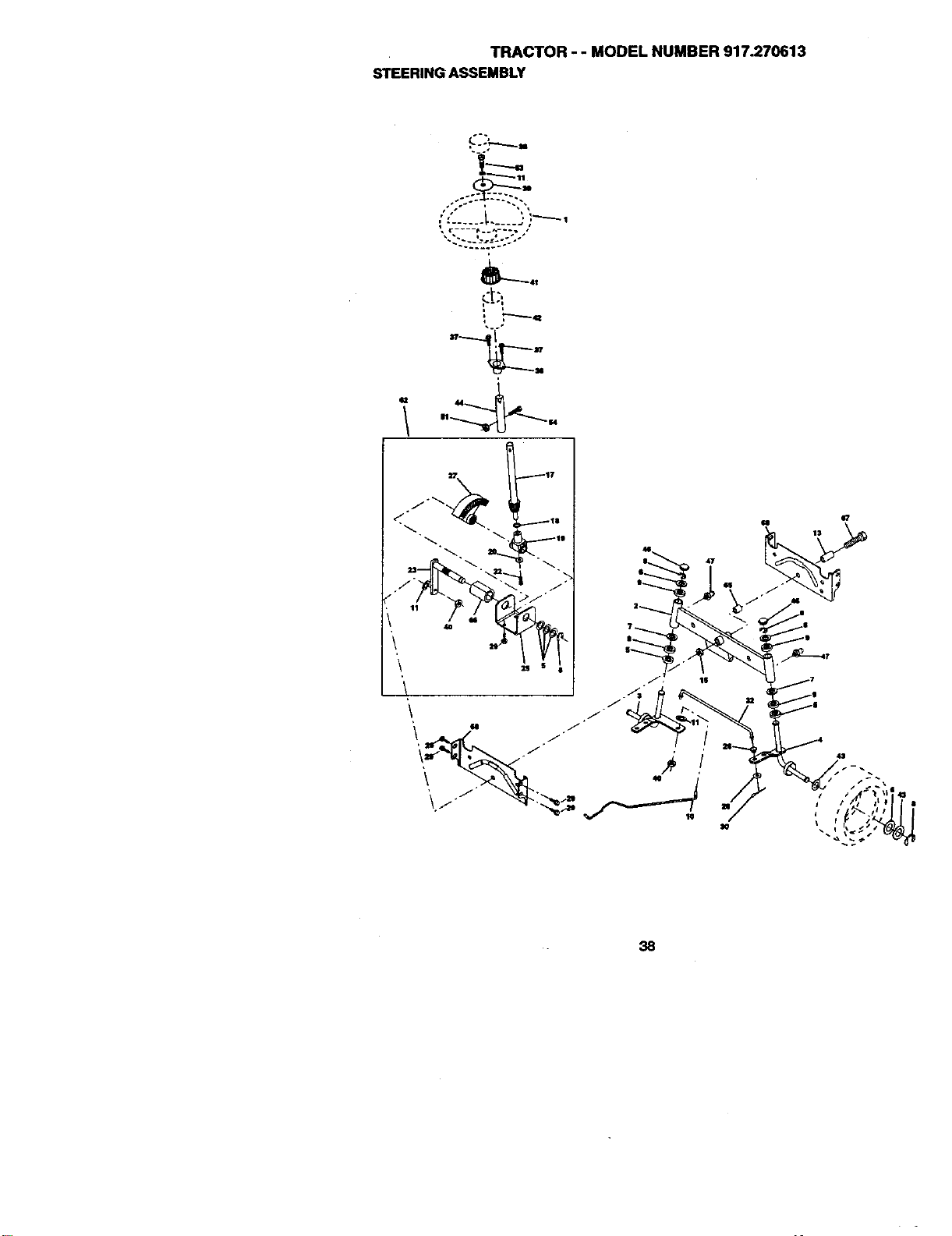
TRACTOR-- MODELNUMBER917.270613
STEERINGASSEMBLY
c-----e.°.,-°°. ,
• -. i J .-/
~.~....°-
L
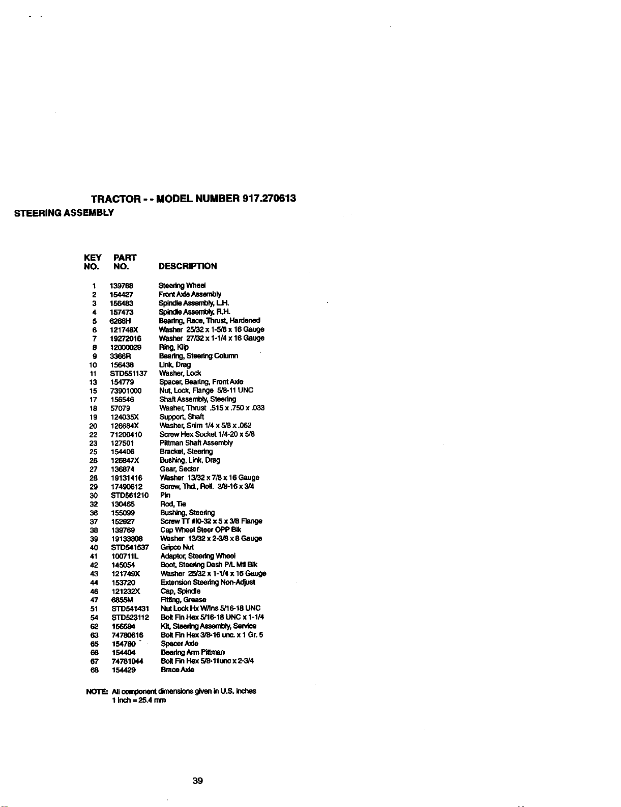
TRACTOR - - MODEL NUMBER 917.270613
STEERING ASSEMBLY
KEY PART
NO. NO. DESCRIPTION
1 139788 Steering Whe_
2 154427 Front Axle Assembly
3 156483 Splndle Assembly, LH.
4 157473 Sp_dle Assembly, R.H.
5 6266H Beadng, Race, Thn_ Hardened
6 121748)( Washer 25/32 x 1-5/8 x 16 Gauge
7 19272016 Washer 27/32 x 1-1/4 x 16 Gauge
8 12000029 Ring, KUp
9 3366R Buadng, Steedng Column
10 156438 _ Drag
11 STD551137 Washer, Lock
13 154779 Spacer, Beadng, Front Axle
15 73901000 Nut, Lock, Flange 5/8-11 UNC
17 156546 Shaft Assembly, Steedng
18 57079 _sher, Thrust .515 x .750 x .033
19 124035X Support, Shelf
20 126684X Washer, Shim 114 x 5/8 x .062
22 71200410 Screw Hex Sockut 1/4-20 x 5/8
23 127501 Pittman Shaft Assembly
25 154406 Bracket, Steedng
26 126847X Bushing, Unk, Drag
27 136874 Gear, Sector
28 19131416 Washer 15/32 x 7/8 x 16 Gauge
29 17490612 Screw, Thd., Roll. 3/8-16 x 3/4
30 STD561210 Pin
32 130465 Rod, "i'w
36 155099 BustCng, Steedng
37 152927 Screw "l'r #10-32 x 5 x 3/8 Flange
38 139769 Cap Wheel Steer OPp Blk
39 19133806 Washer 13t32 x 2-3/8 x 8 Gauge
40 STD541537 Gdpco Nut
41 100"/11L Adaptor, Steering W11eel
42 145054 Boot, Steeflng Dash PA. Mtl l_k
43 121749X Washer 25/32 x 1-1/4 x 16 Gauge
44 153720 Extension Steedng Non-Adjust
46 121232X Cap, Spin_e
47 6855M Fitting, Grease
51 S'1_541431 Nut Lock Hx W_lns 5PI6-18 UNC
54 STD523112 Bolt Fin Flex 5/16-18 UNC x 1-1/4
62 156594 Kit,SteeJ',ngAssent_y,,Se_:e
63 74780616 BORFin Hex 3/6-16 uric. x I Gr. 5
65 154780 " Splicer ._de
66 154404 Beadng Arrn Pl_rnan
67 74781044 Bolt Fin Hax 5/8-11 unc x 2-3/4
68 154429 Brace AxJe
NOTE:
_ connpone.tdmens_ g_n _nU.S.k_s
I Inch = 25.4 ran1
39
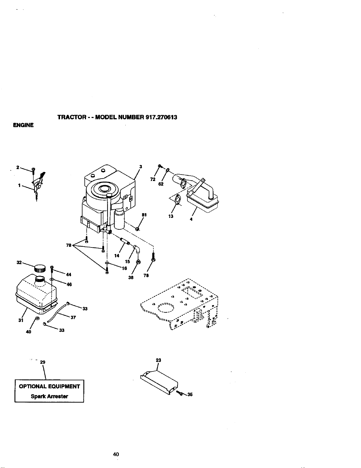
ENGINE
TRACTOR-- MODELNUMBER917.270613
• 1
3
81
14 15
38
13
78
." _ ._._:I_ ri_ _.
_._ s3 _'_ .._" _ ."1
.. it: : #
I
OPTIONAL EQUIPMENT
Spark Arrester
I
23
4O

ENGINE
TRACTOR - - MODEL NUMBER 917.270613
KEY PART
NO. NO. DESCRIPTION
1 162157 Control "rhrot/Ch Lh
2 17720410 Screw Hex Thd Cut 1/4-20x5/8 T
3 ........ Engine (See Breakdown) B&S Model 28U707.1174-E1
4 137352 Muifler Exhaust B&S Lt
13 165291 Gasket 1 313 Id T_ Plated
14 13280324 Nipple Pipe 3/8 Npt X 3"
15 132003(]0 L=lbowStd 90 Degree 3/8-18 Npt
16 STD551237 Washer Lock ExLTooth 3/8
23 159880 Shield Brown]ng/Debds Guard
29 137180 Arrestor Spark
31 1092QP.X Tank Fuel 1 25 Fr
32 158990 Cap Asnt Fuel Sears Ventod
33 123487X Clamp Hose BIk
35 174_9G512 Screw, "l_rol 5/16-18 x 3/4 Tyt
37 137040 I.k_ Fuel 20"
38 ...... Plug Oil Drain (Order From Engine Manufacturer)
40 124G28X Bushing Snap Nyt BIk Fuel Une
44 17490412 Screw Hexwsh "nldrol 1/4-20x3/4
46 19091416 Washe_ 9/32 X 7/8 X 16ga
62 STD551131 Washer"Lock Hvy Hlel Spr 5116
72 71070512 Screw He}did Cap 5116-18x3/4
78 17490620 Screw "gldrol 3/8-16x1-1/4 Tytt
81 128861 Nut Flange 114-20 Starter Nut
NO'rE:NI componentdlrner_.aionsgivenInU.S. _hes
1_lch= 25,4 mm
41
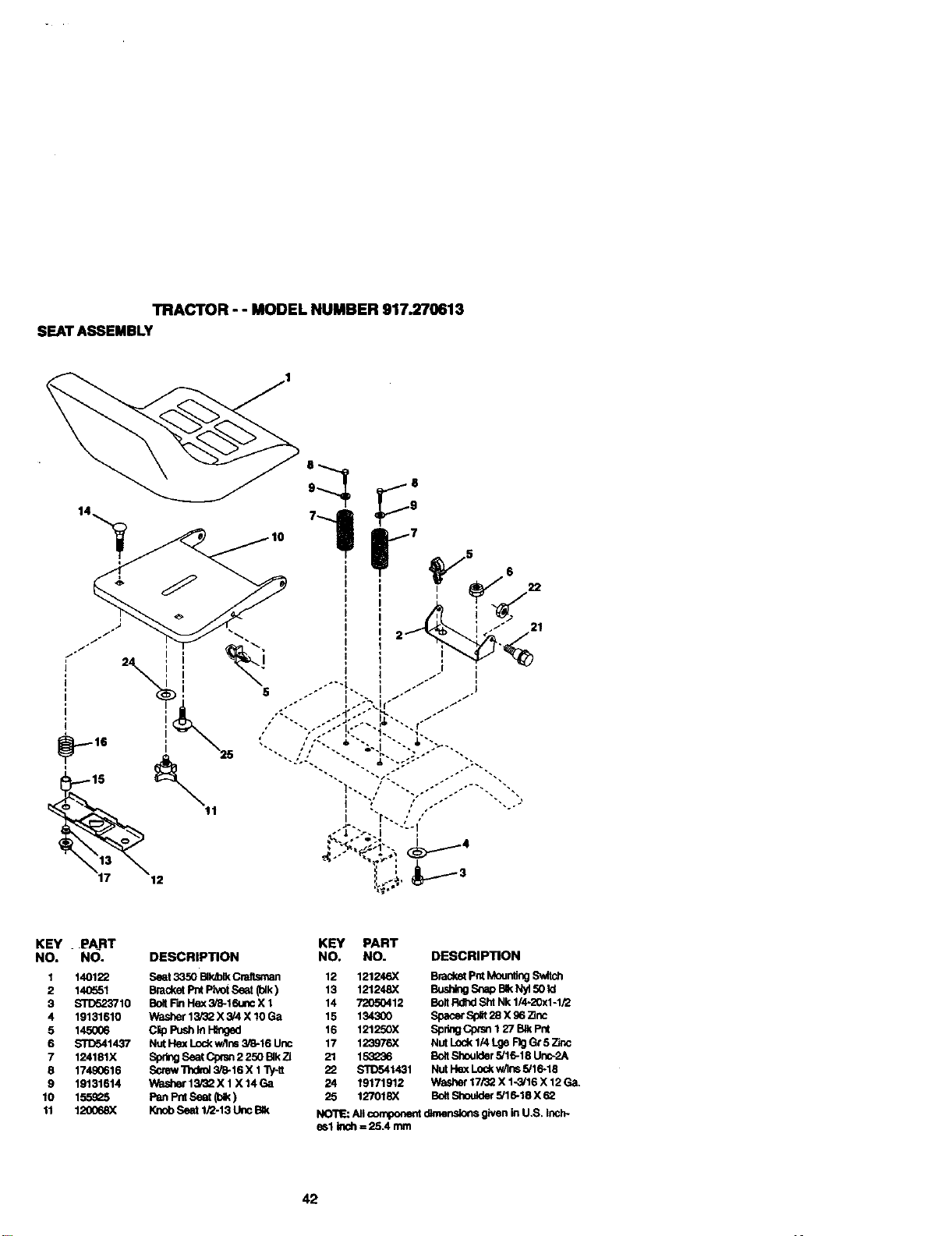
TRACTOR -- MODEL NUMBER 917.270613
SEATASSEMBLY
KEY . PART KEY PART
NO. NO. DESCRIPTION NO. NO. DESCRIPTION
1 140122 Seat 3350 BII_H( C_ 12 121246X Br'dck_ pnt Moun1_g Sv,4tch
2 140551 Bracket Pnt Pivot Seat (blk) 13 121248X Bushing Snap BIk Nyt 50 Id
3 STD523710 Bolt Fin Hex 3_-16unc X 1 14 72050412 Bolt Rdhd Sht Nk 1/4-20x1-1/2
4 19131610 Washer 13/32 X 3/4 X 10 Ga 15 134300 Spac_ Split28 X 96 Zinc
5 145006 Clip Push In H_ged 16 121250X Spdng Cprsn 1 27 BIk Pnt
6 STD541437 Nut Hex Loc_ w_lns3/8-16 Uric 17 123976X Nut Lock 1/4 Lge F)g Gc5 _Jnc
7 124181X Sprf_ Seat Cp_l 2 250 BIk Z] 21 153236 Bolt Shoulder 5/16-18 Ur_-2A
8 17490616 Screw "nldfo_3/8-16 X 1Ty-tl 22 _1431 Nut Hex Lod_w/Ins 5/16-18
9 19131614 V_;ler 13,3Q X 1X 14 Ga 24 19171912 Washer 17/32 X 1-3/16 X 12 Ga.
10 1559_ Pan Pnt Seat (bH<) 25 127018X BottShould_ 5/16-18 X 62
11 120068_ Knob Seat lJ2-13 I.k_ BIk NO'I_: An component dimensions given in U.S, Inch-
es1 Inch = 25A mm
42
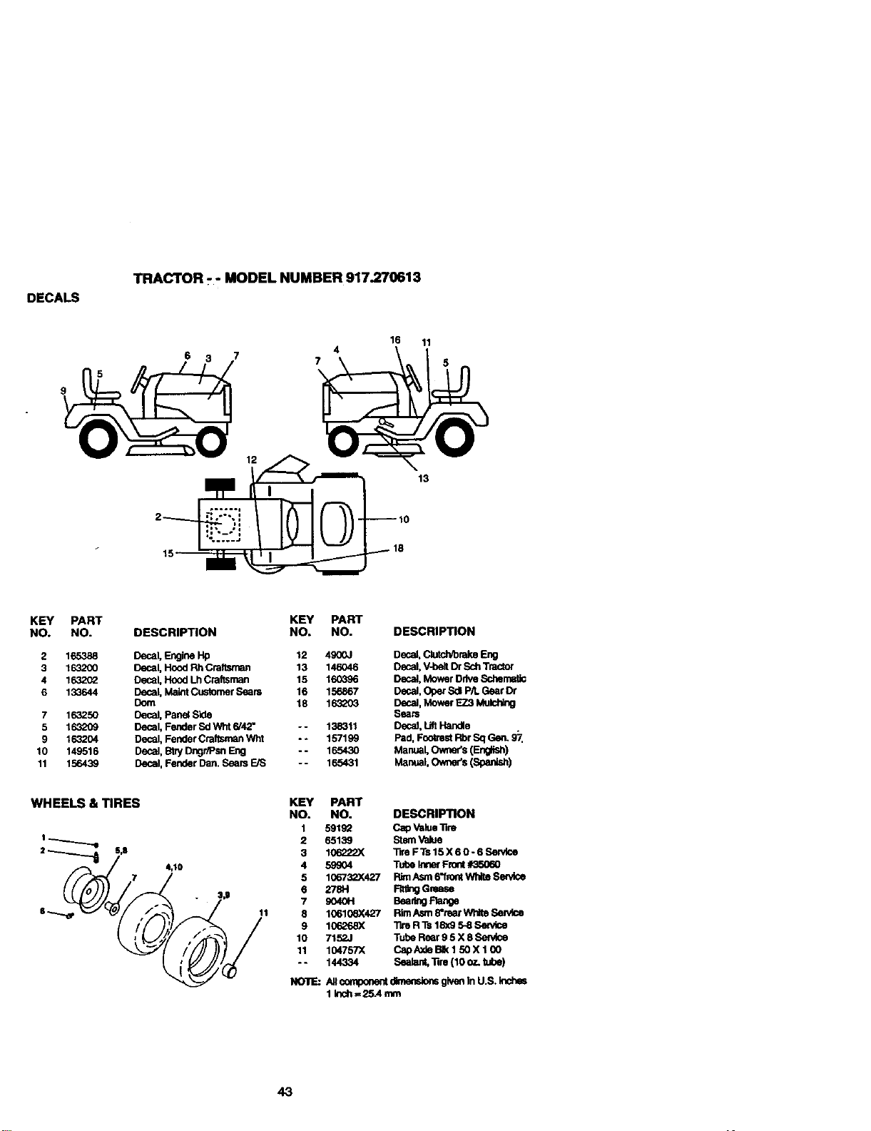
DECALS
TRACTOR - - MODEL NUMBER 917.270613
12
4
7
16 11
13
KEY PART KEY PART
NO. NO. DESCRIPTION NO, NO.
2 165388 Decal, Engine PIp 12 49(X)J
3 163200 Decal. Hood Rh Craftsman 13 146046
4 163202 Decal, Hood Lh Craftsman 15 16(_6
6 133644 Decal, Malnt Customer Sears 16 156867
Dora 18 163203
7 163250 Decal, Pane{ Side
5 163209 Decal, Fender Sd Wht 6/42" -- 138311
9 163204 Decal, Fender Craftsman Wht -- 157199
10 149516 Decal, Btry Dngr/Psn Eng - - 165430
11 156439 Decal, Fender Dan. Sears E/S -- 165431
DESCRIPTION
Dec=,Outd_rakeEng
Decal, VJoelt Dr Sch Tractor
Decal, Mower Drive Schenlst_
Decal, Oper Sdl P/L Gear Dr
Decal, Mower EZ3 Mulcl_r,g
Sears
Decat, Lift Handle
Pad. Foolrest Rbr Sq Gen. 9"I.
Manual,Owner's(F_ng_)
ManuaJ,Owner's(Spa_sh)
WHEELS & TIRES
o_ s,a
4,10
11
KEY PART
NO. NO. DESCRIPTION
I 591g_ Cap Value Tim
2 6513_ Stem Value
3 101_22X Ttre F Ts 15 X 6 0.6 Service
4 59904 Tube Inner Flont #35060
5 106732X427 Rim Asm 6"flo_ Whh Sen/ice
6 278H F_ngGrease
7 S040H Beade0Range
8 106106X427 Rim Asrn 8"rear White Se_k:e
9 10626_ Tire R TO16x9 5-8 SetV,ce
10 7152J Tube Rear 9 5 X 8 _
11 104757X CapAxle I_ 1 50 X 1 00
-- 144334 Sealant, Tire (10 oz. tube)
Allc_nponentdime_._ givenInU.S. Inches
1 klch.=25.4 mm
43
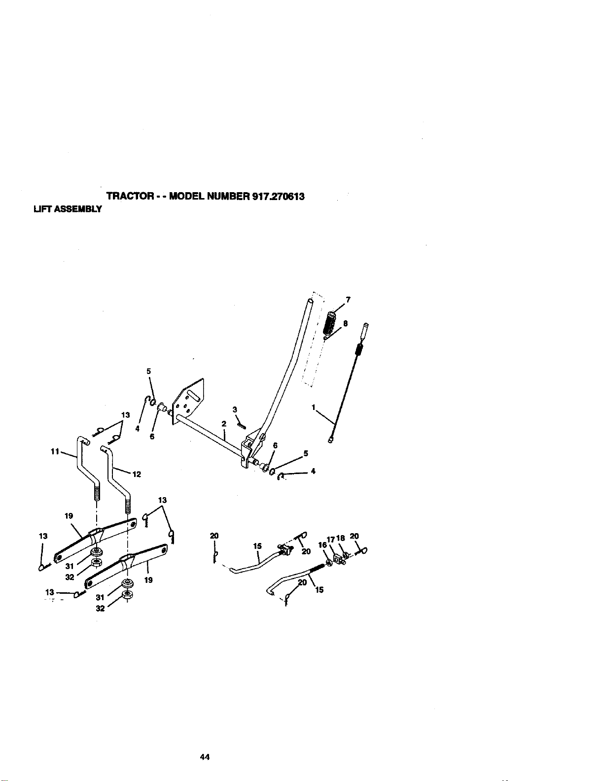
TRACTOR - ' MODEL NUMBER 917.270613
UFT ASSEMBLY
13
3
6
19
13
32
13_
32
13
19
2O
44
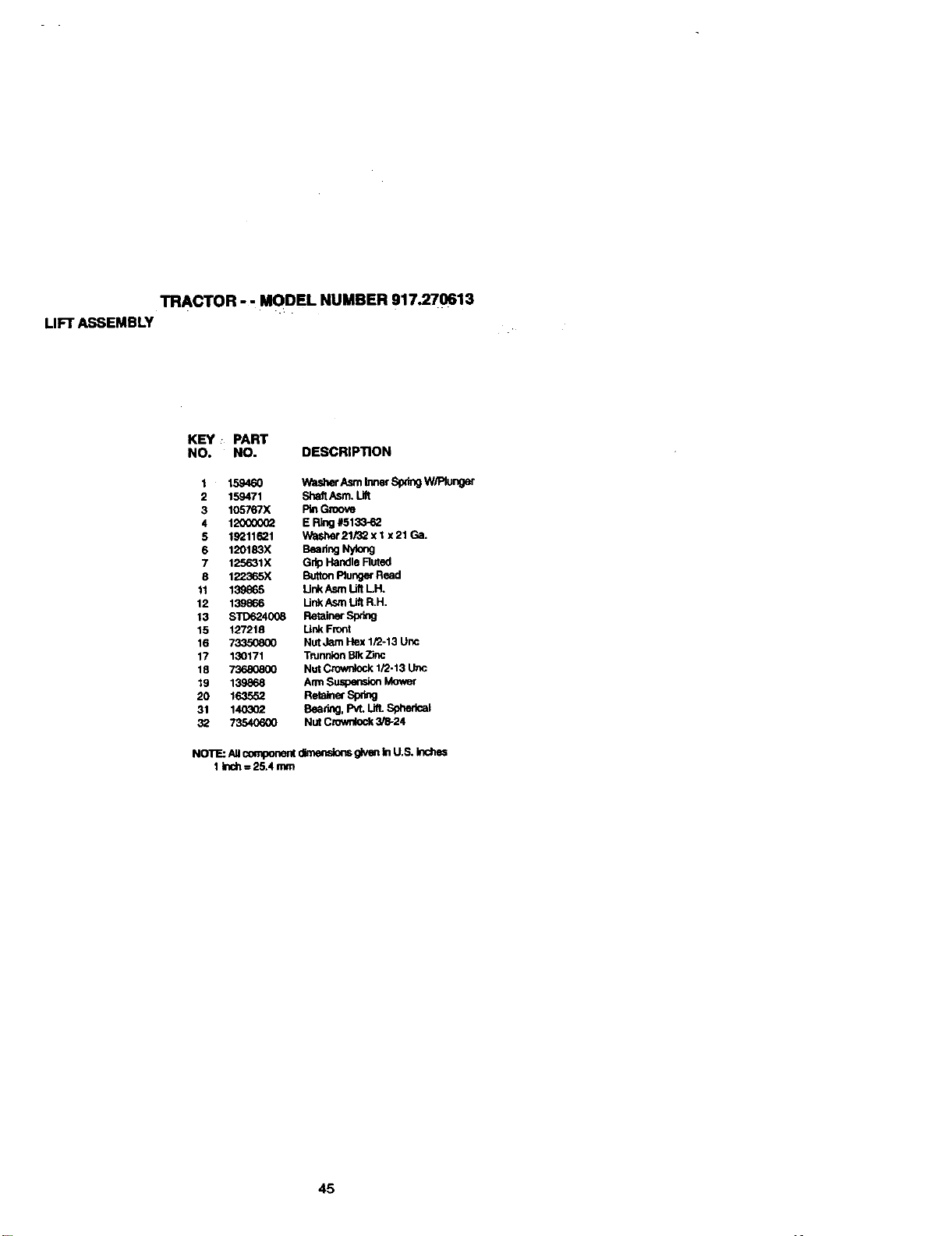
TRACTOR - - MODEL NUMBER 917.270613
LIFT ASSEMBLY
KEY : PART
NO. NO. DESCRIPTION
1 15946O Washer Asm Inner Spdng W/Rur_er
2 159471 Shah Asm. Lilt
3 105767X _ Groove
4 12000002 E Ring #513_62
5 19211621 Washer 21/32 x I x 21Ga.
6 120183X Beadng Nylong
7 125631X Grip Handle Ruled
8 122365X Button Plunger Read
11 139865 Ul_ Asm I.JftLH.
12 139866 Unk Asm I.ift R,H.
13 STD624008 Retainer Spdng
15 127218 Unk Frc_t
16 73350800 Nut Jam Hex 1/2-13 Ur_
17 130171 Trunnion BIk Zinc
18 73680800 Nut Crownlock 1/2-13 Uric
19 139868 Arm ,_Jspension Mower
20 163552 Rel_ef Sprig
31 1403_ Bear_g,PvLLi_ SphedcaJ
32 73540600 Nut Crownlock 3/8-24
NOTE: Allcomponerd dimensions _ In U.S. blches
1 blch= 25A mm
45
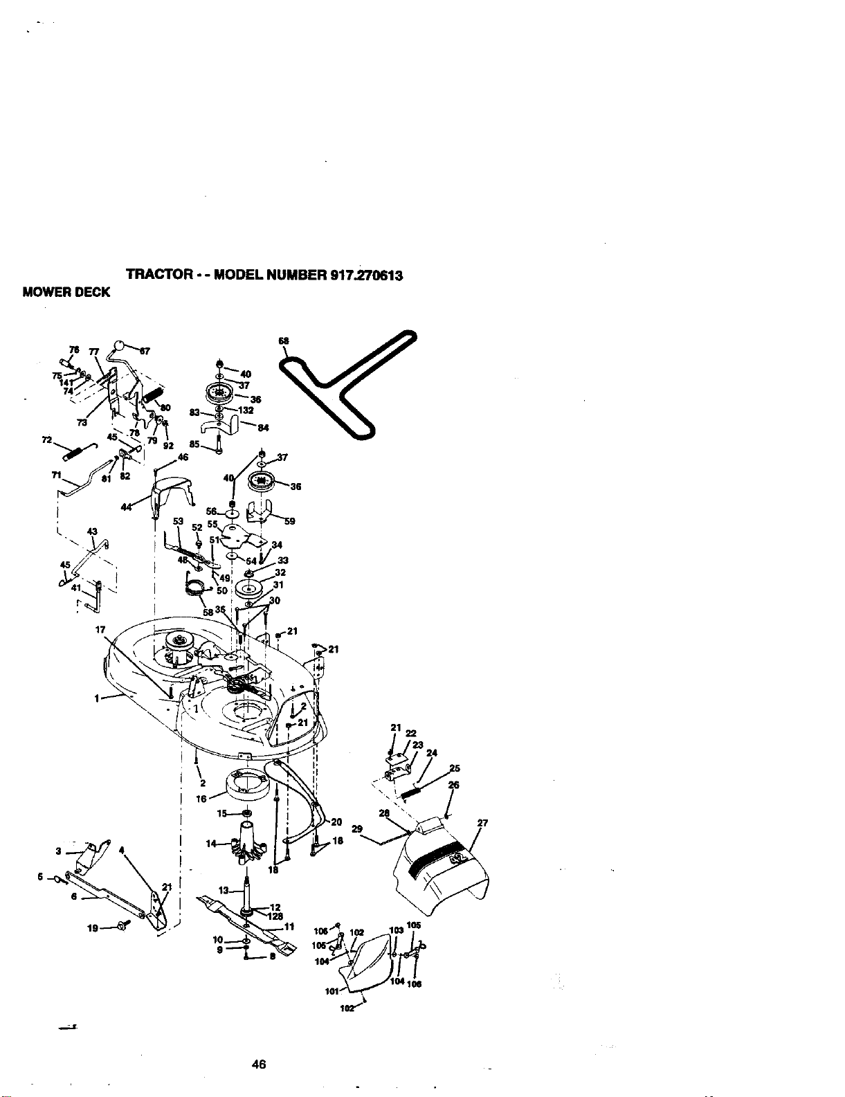
TRACTOR - - MODEL NUMBER 917.270613
MOWER DECK
i
L 43
17
\
46
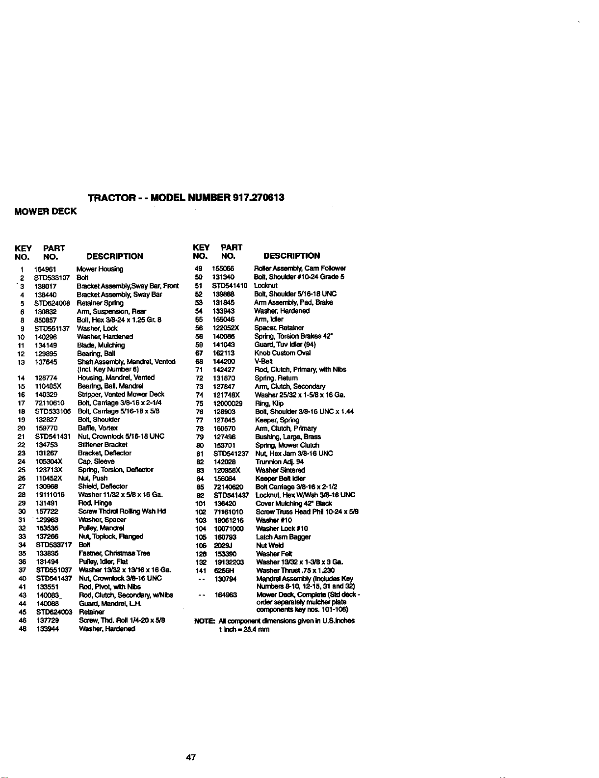
TRACTOR - - MODEL NUMBER 917.270613
MOWER DECK
KEY PART
NO. NO.
I 164961
2 STD533107
"3 138017
4 138440
5 STD624008
6 13O832
8 85O857
9 STD551137
10 140296
11 134149
12 129895
13 137645
14 128774
15 110485X
16 140329
17 72110610
18 STD533106
19 132827
20 159770
21 STD541431
22 134753
23 131267
24 105304X
25 123713X
26 110452X
27 130968
28 19111016
29 131491
30 157722
31 129963
32 153535
33 137266
34 STD533717
35 133835
36 131494
3? STD551(_'/
40 STD541437
41 133551
43 140083
44 140088
45 STD624003
46 137729
48 133944
KEY PART
DESCRIPTION NO. NO. DESCRIPTION
MowerHousing 49 155066 RollerAssembly,CamFollower
Boft 50 131340 Bo_t,Should_"#10-24Grede5
BracketAssembly,SwayBar,Front 51 STD541410 Locknut
BracketAssembly,SwayBar 52 139e88 Bolt,Shoulder5/16-18 UNC
RetainerSpdng 53 131845 ArmAssembly,Ped,B_ake
Arm,Suspension,Rear 54 133943 Washer'Hardened
Bolt,Hex3/8-24 x 1.25Gr.8 55 t55046 Arrn,Idler
Washer,Lock 56 122Q52X Spacer,Retainer
Washer,Hardened 58 140_86 Spring,TorsionBrakes42"
B1ede,Mulching 59 141043 Guard,Tuv Idler(94)
Beadng,Boll 67 162113 KnobCustomOval
ShaftAssembly,Mandnd,Vented 68 144200 V-Bo,
(Incl.Key Number6) 71 142427 Rod,Clutch.Pdmar/,wi_ Nibs
Housing.Maedml,Vented 72 131870 Spdng,Return
Bearing,Ball,Mandrel 73 127847 Arm,CkJtch,Secondary
Stripper,VentedMowerDeck 74 121748X Washer25/32x 1-5i8x16 Ga.
Bolt,Carriage3/8-16x 2-1/4 75 12000029 Ring,Klip
BOlt,Carrlage5/16-18x 5/8 76 128903 BOlt.Shoulder3/6-16UNC x1.44
Bolt.Shoulder 77 127845 Keeper,Sp_
Bolfle, Vortex 78 160570 Arm,Clutch,Pdmary
Nut,Crownlock5/16-18 UNC 79 127498 Bushing.Large,Brass
StiffenerBracket 80 153701 Spring,MowerClutch
Bracket,Deflector 81 STD541237 Nut,HexJam3/8-16UNC
Cap,Sleeve 82 142028 TrunnionAdj.94
Spdng,Torsion,Deflector 83 120_8X WasherStnterad
Nut, Push 84 156_4 KeeperBeltIdler
Shle_l,Deflector 85 72140620 BoltCarhage3/6-16x2-1/2
Washer11/32x5i8x16Ga. 92 STD541437 Locl<nut,HaxWN,'sh3/8-16UNC
Rod, Hinge 101 136420 Co_r Mulcting42"Black
ScrewThdrolRollingWsh Hd 1(_2 71161010 ScrewTrussHeadPhil10-24x5/8
Washor,Spacer 103 19061216 Washer#10
Pulley,Mandrel 104 10071000 WasherLock#10
Nut,Topleck,Ranged 105 160793 LatchAsmBagger
Bolt 106 2029.1 NutWeld
Fastner,Ch_ Tree 128 153390 Y_sh_r Felt
Pugey,Idler. Flet 132 1913_0_ Washer13_2 x 1-3/8x 3Ga.
Washar13/32 x 13/16x 16Ga. 141 6266H Washer"l_ruet.75x 1.230
Nut.Cm',wCock3/8-16UNC -- 130794 MandrelAssembly(Inc_,desKey
Rod,Pivot,withNits Numbers8-10,12-15, 31 and32)
Rod,Clutch,Secondary,w/N_s -. 164..o63 MowerDeck,Complete(Stddeck-
Guard,Mandrel,LH. orderseparatelymuk:P,er plate
Retainer componenetkey nos.101-106)
Screw,Thd_Roll1/4-20 x5/8 No'InE:AI compone_dimenslensgiveninU.S.Inshes
Washer,Hardened 1k_h = 25.4 mm
47
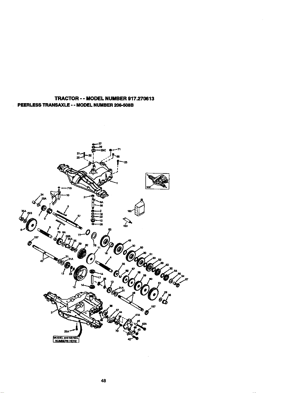
TRACTOR - - MODEL NUMBER 917.270613
PEERLESS TRANSAXLE - - MODELNUMBER206-508B
9
706A
48
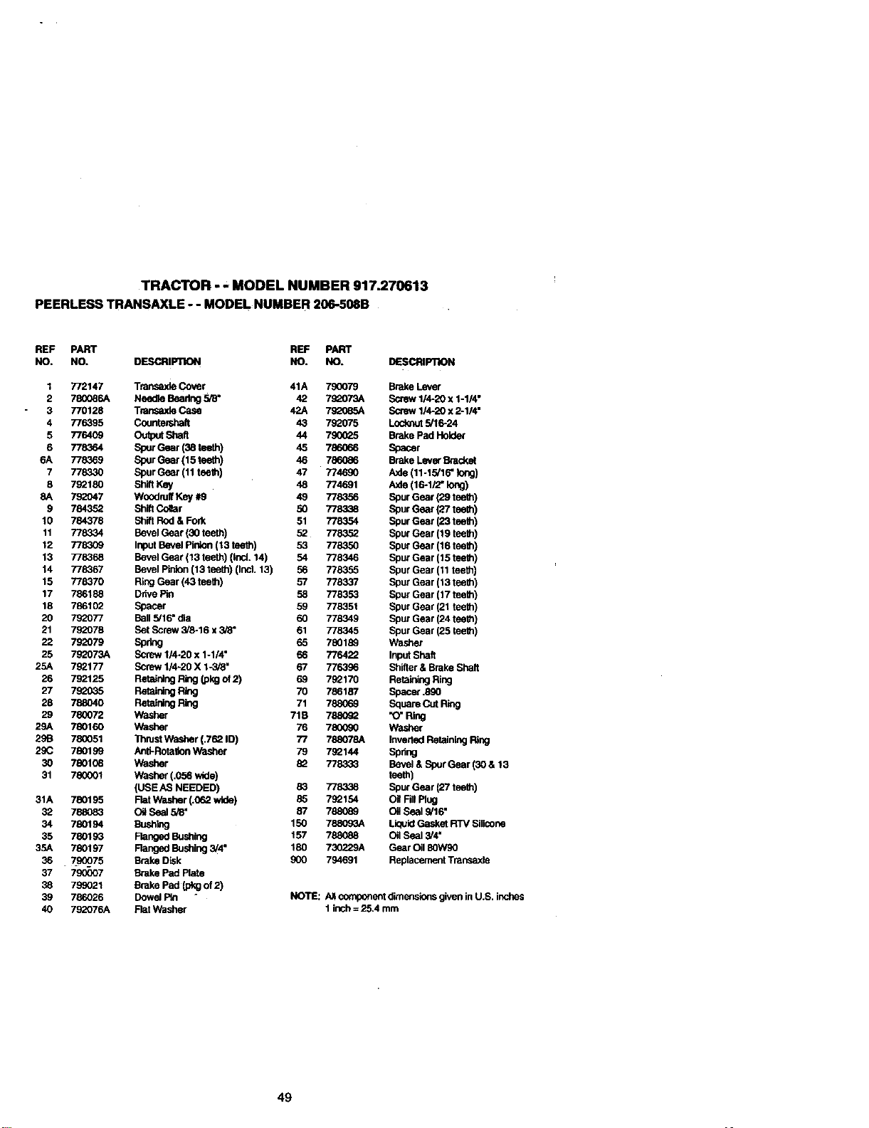
TRACTOR -" MODEL NUMBER 917.270613
PEERLESS TRANSAXLE - - MODEL NUMBER 206-508B
REF PART REF PART
NO. NO, OESCRIPTION NO. NO. DESCRIPllON
I 772147 Transa)de Cover 41A 790079 Brake Lever
2 780086A Nea_e Beadng 5/6" 42 790073A Soew 1/4-20 x 1-1/4"
3 770128 Transaxle Case 42A 7g_:_85A Screw 1/4_20 x 2-1/4"
4 776395 Cou_h 43 790075 Loc_ut 5/16-24
5 776409 Output Shah 44 790025 Brake Pad Holder
6 778364 ,_our Gear (38 16eth) 45 786066 Spacer
6A 778369 Spur Gear (15 teeth) 46 786086 Brake Lever Bracket
7 778330 Spur Gear (11 teath) 47 774690 Axle (11-15/16" k_ng)
8 790180 Shift Key 48 774691 Axle (16-1/2" long)
8A 792047 Woodruff Key #9 49 778356 Spur Gear {29 teeth)
9 784352 Shift Collar 50 778338 Spur Gear (27 teeth)
10 784378 Shih Rod & Fork 51 778354 Spur Gear (23 teeth)
11 778334 Bevel Gear (30 teeth) 52 778352 Spur Gear (19 teeth)
12 778309 Input Bevel Pin_on(13 teeth) 53 778350 Spur Gear (16 teeth)
13 778368 Bevel Gear (13 teeth) (IncL 14) 54 778346 Spur Gear (15 teath)
14 778367 Bevel Pin:on (13 teeth) (Incl. 13) 56 7783.55 Spur Gear (11 teeth)
15 779070 Ring Gear (43 teeth) 57 778337 Spur Geer (13 teeth)
17 786188 Ddve Pin 58 778353 Spur Gear (17 teeth)
18 786102 Spacer 59 778351 Spur Gear (21 teeth)
20 792077 Bell 5/16" dia 60 778349 Spur Gear (24 teeth)
21 792078 Bet Screw 3/8-16 x 3/8" 61 778345 Spur Gear (25 teeth)
22 792079 Spring 65 780190 Washer
25 790073A Screw 114-20 x 1-1/4" 66 776422 Input Shah
25A 792177 Screw 1/4-20 X 1-3/8" 67 776396 Shifter & Brake Shaft
26 792125 Reta_nthgRing 00kgof 2) 69 790170 Rofelutng Ring
27 7S_35 Retaining Ring 70 786187 Spacer .890
28 788040 Retaining Ring 71 78806_ Square Cut R_j
29 780072 Washer 71B 788090 "O" Ring
29A 780160 Washer 76 780090 Washer
29B 780051 Thrust Washer (.762 ID) 77 788078A Inverted Retaining Ring
29(; 780199 AnU-Rotatlon V_Pasher 79 790144 Spring
30 780108 Washer 90 778333 Bevel & Spur Gear (30 & 13
31 780001 Washer (.056 wide) teeth)
(USE AS NEEDED) 83 7783_ Spur Gear (27 teeth)
31A 780195 Flat _ar, het (.062 wide) 85 790154 O] Fill Ping
32 788083 Oil Seal 5/8' 87 788089 Oil Seal 9/16"
34 780194 Bush_g 150 788090A Liquid Gasket R'rv Silicone
35 780193 Flanged Bushing 157 788088 Oil Seal 3/4"
35A 780197 Ranged Bushing 3/4" 180 730229A Gear Oil 90W90
36 7900_75 Brake Disk 900 794691 Replacement Transaxla
37 790007 Brake Pad Plate
38 799021 Brake Pad _ of 2)
39 786026 Dowel Pin NOTE: A_ component dimensions given in U.S. inches
40 792076A Flet washer 1 inch = 25.4 mm
49
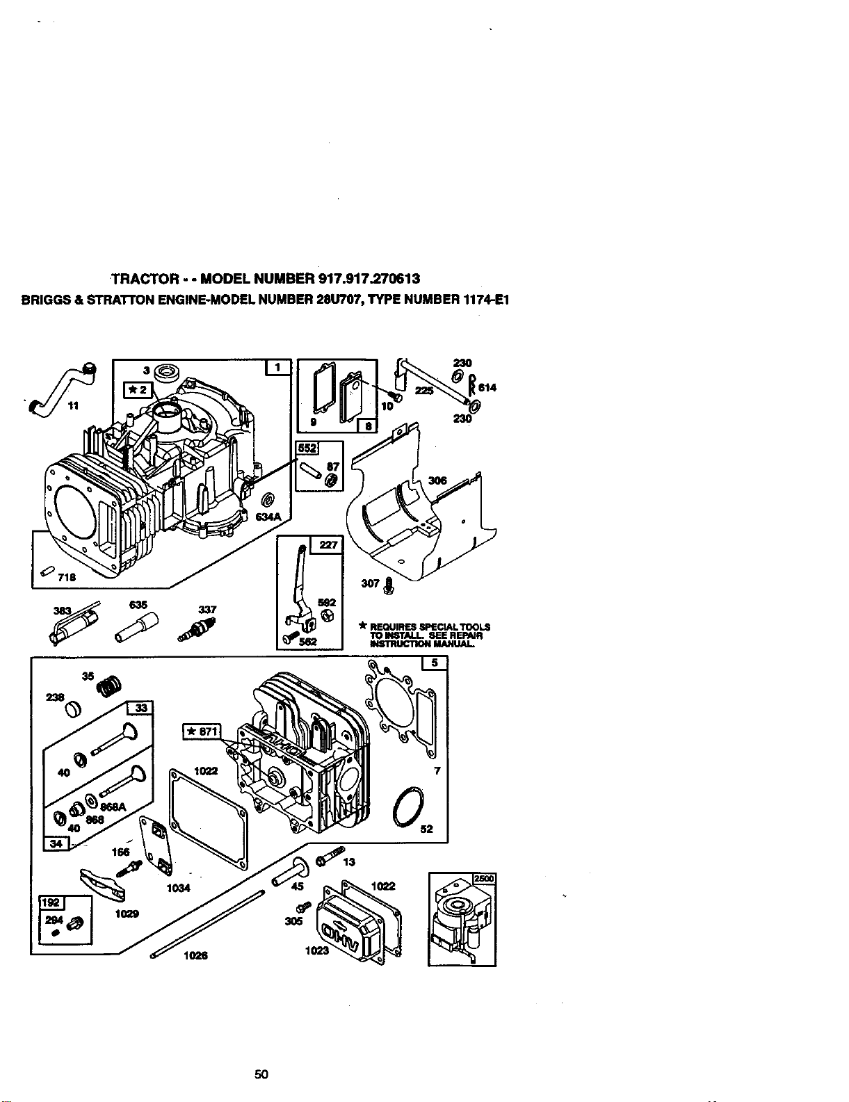
TRACTOR-- MODELNUMBER917.917.270613
BRIGGS & STRAI"rON ENGINE-MODEL NUMBER28U707, TYPE NUMBER 1174-E1
• _11 230 614
_k"REQUIRES SPECIAL TOOLS
TO INSTALL. SEE REPAm
INSTRUCTION MANUAL.
1026
5O
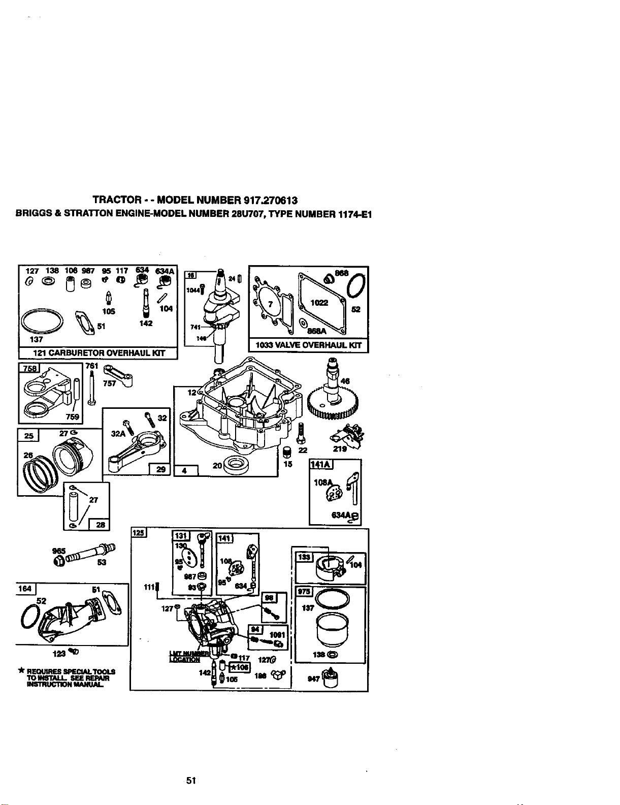
TRACTOR - - MODEL NUMBER 917.270613
BRIGGS & STRAI"rON ENGINE-MODEL NUMBER28U707, TYPE NUMBER 1174-E1
127 138 106987 _ 117 _ _e
51 142
137
121 CARBURETOR OVERHAUL lOT
27G,
1033 VALVE OVERHAUL Kn"
51
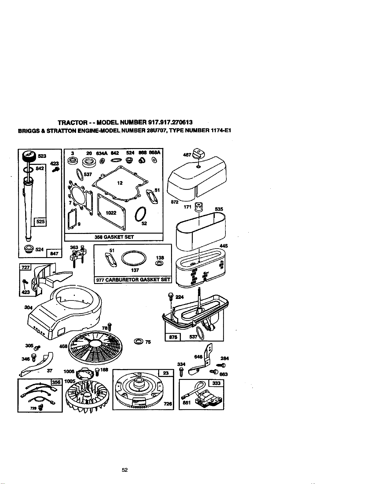
TRACTOR-- MODELNUMBER917.917.270613
BRIGGS&STRA'I'rONENGINE-MODELNUMBER28U707,TYPENUMBER1174-E1
1006
I
3,58GASKET SET
171 _ 535
445
334
663
52
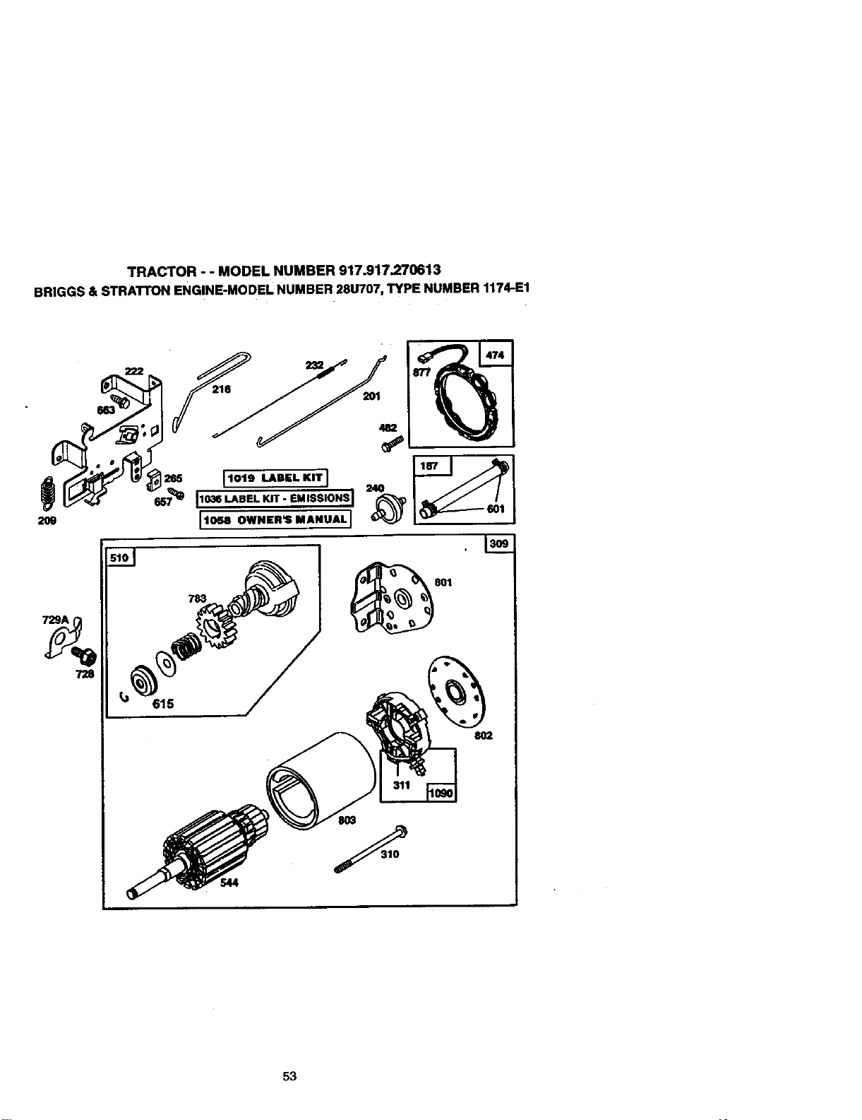
TRACTOR - - MODEL NUMBER 917.917.270613
BRIGGS & STRATrON ENGINE-MODEL NUMBER 28U707, TYPE NUMBER 1174-E1
209
729A
783
615
544
801
8O2
53

TRACTOR-- MODELNUMBER917.917.270613
BRIGGS&STRATrONENGINE-MODELNUMBER28U707,TYPENUMBER1174-E1
KEY PART KEY PART
NO. NO. DESCRIPTION NO. NO. DESCRIPTION
1 496412 _Assembly 93 281346 Bushing, Throttle Stmft
2 399265 Bearing, Cyitnd_r 94 496030 Valve, Needle
3 391086 " SeaI, OU 95 94098 *" Scmw, Thrott_
4 494238 Base,_ 96 495800 Scmw, ldtaSpeed
5 4S5858 Head, Cylinder 104 231789 " Pin FIoatHInge
7 273280 *" Gasket, CyitnderHead 105 231855 " ValveRoat
8 495735 Breather.AJZSemb_ 106 231854 "Scat, inlelVal_e
9 27803 * Gasket, ValveCover 108 224558 Valve, C;loke(Lmt153)
10 94621 Screw, Seres I08A 224540 Valve, Choke (Lint 154)
11 281246 TuUe, Bmather 11_1 262715 SpringChoke(Lmt155)
12 271916 * Gasket. Cra_ Cover, .015" 117 23Ql18 ** Jet.NeedtaVelve(Std,)
271997 • Gasket, Crankcase Cover, .005 ° 232119 Jet, Needle Valve (Hi-AlL)
271996 " Gasket. Cmnkcase Cover, .009" 121 499233 CarburetorOverhaulK]t
13 94728 Screw, Cyf_ Head 123 94913 Screw, Elbow Moun6ng
15 94239 Plug, Oil Drain 125 499153 CarburetorAssembly
16 488971 Crankshaft 127 -- - _ Plug, Welch (Sold in Kit Only)
94196 Trning Gear Key 130 224539 Valve, lllroltle
20 291675 * Seal, Oil 131 494379 Shaft and Lever, "/TzrotUe
22 94624 Screw, Sems, Base Mounting 133 494381 Float. Carburetor
23 492326 Flywheel and Ring Gear 137 281165 .... Gasket, Roat Bowl
_, Magneto 138 281164 .... Washer.Bowl
24 222696 Key, _ 141 485097 Choke, Shaft 10t (CCloke-A-
25 495860 PIstonAssembly, Standard Size Marc)
495977 Piston Aseamb4y, .010" 141A 485931 Choke, Shaft }Qt (Choke-A.
Oversize Marc)
495978 PistonAssemb/y, 020" 142 232117 °* NozzJe, Carburetor
Oversize 146 94196 Key, T_ Guar
495979 PIstorl AssendY_, ,030" 164 214047 Elbow, Cad0uretor
Ovemlze 166 94555 Stud, RockerArm
26 495854 RlngSet, Piston, StondardSIze 171 281051 Nut, AirCleanerMou_Ewlg
495852 R_g Set, Piston, .010" Ovemize 186 4_496 Connector, Hose
4_5851 Ring Set, Piston, .020" Oversize 187 2_099 Line, Fuel {Cut to Suit)
4_B55 Ring Set, Piston, .0_0" Oversize 188 94627 Screw, Serns
27 263129 Lock, Piston Pin 192 492160 ScrewAssembly, RockerArm
28 498319 Pin Assy., Piston, Standard Size 201 2_767 Unk, Governor
498320 Pin Ass,/., Ph;ton, .005" 2(;9 260685 Spdng, Governor
Oversize 216 262766 Unk, Choke
29 494504 RodAsserndly, Connecting 219 490815 Gear, Governor
495490 Rod Assembly, CoNlecit_, 222 485611 Plate, Governor Contrel
.020" Undersize Crankpin Bore 224 94905 Screw, Scms, Air Cleaner
32 94695 Screw, Hex Washer Head, 225 4S5157 Crank, Governor
1.57/64
32A 94648 - Screw, H_< Washer Head, 1- 227 493935 Lever Assembly, Governor
5/8 230 94742 V_zshar, Governer Cra_k
33 495856 Valve, Exhaust - 232 262785 Sprig, Governor Unlk
34 4S5857 Valve. Intake 238 262836 Cap. Valve
35 262811 Spring, Valve 240 394358 Rlter, Fuel (in Fuel Line)
37 224502 Guard, _ 265 221535 Clamp, Ca_ng
40 224641 Retainer, Valve Spring 284 94704 Screw, Hex Head
45 262411 Tappet, Valve Included in Gasket Set (4959_)
46 496884 Gear, Cam incinded in Carburetor I_ (499233)
51 272465 .... Gasket, Cad_Jmt_ "* Included in bo_ Gasket Set (495993) and
(Carburetor to E]lx)w) Valve Oved'mul IQt (495992)
52 272569 "* Gasket, Car_tof *°" Included in Gasket Set (495993), Carburetor
(Elbow to Cylnder) Kit (499233) and Carburetor Gasket Set
53 94637 Stud, Cad_xetor Moun_ng (494385)
75 225136 Washer, Spring
78 94_ Screw, PanHeed NOTE: AqcomponentdmenslonsgiveninU.S. inches
87 491323 *SeaI, GovemorShaft 1 ir_h=25.4mm
54
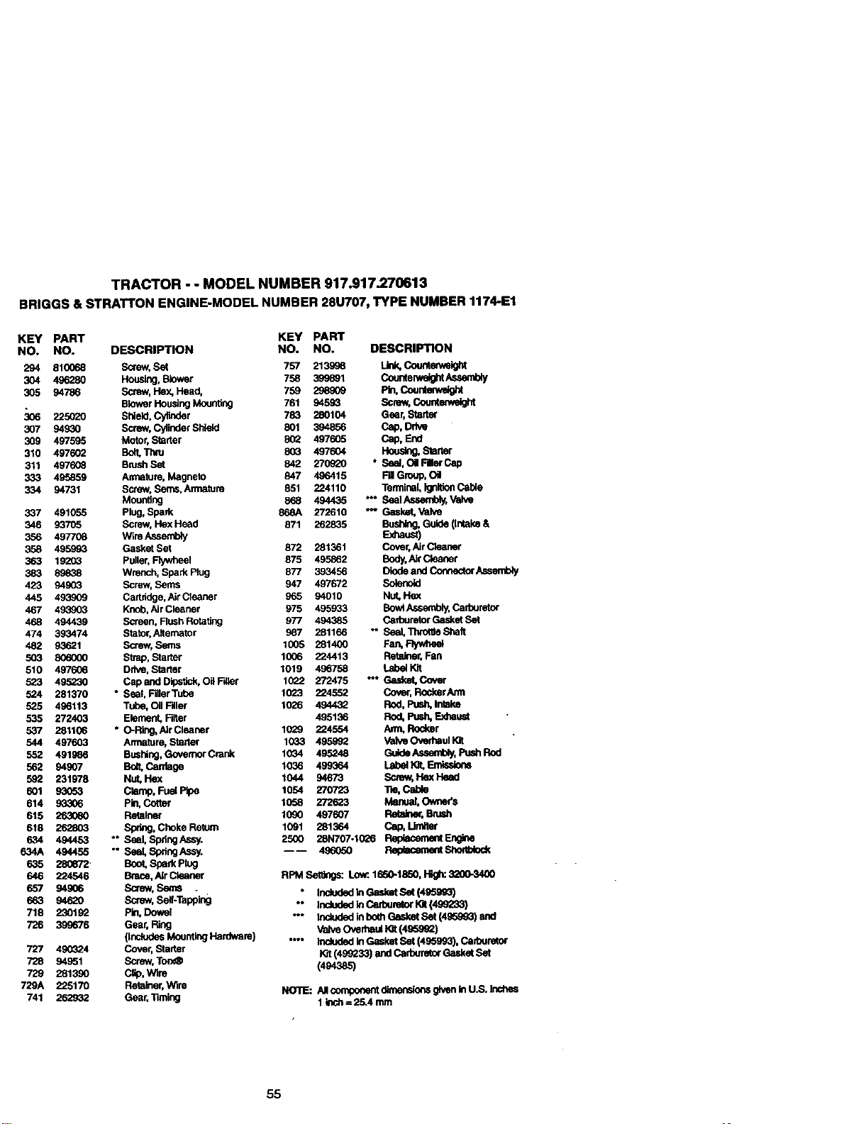
TRACTOR - - MODEL NUMBER 917.917.270613
BRIGGS & STRATTON ENGINE-MODEL NUMBER 28U707, TYPE NUMBER1174-E1
KEY PART KEY PART
NO. NO. DESCRIPTION NO. NO. DESCRIPTION
294 810068 Screw, Set 757 213996 LIrlk, Countew,,elg_
304 496280 Housing, Blower 758 399891 Counte;welglztAseambly
305 94786 Screw, Hex, Head, 759 298909 P_, Countew_ight
Blower Housing Mounting 761 94593 Screw, Counlem.elght
_6 225020 Shield, Cyfinder 783 280104 Gear, Starter
307 94930 Screw, Cylinder Shield 801 394856 Ce4), Drive
309 497595 Motor, StaRer 80_ 497605 Cap, End
310 497602 Bolt, "r;lru 803 497604 Housing, Slarter
311 497608 BmshSet 842 270920 *Seal, OltFllterCep
333 495859 Armature, Magneto 847 496415 Fill Group, Oil
334 94731 SCreW,Seres, Armature 851 224110 Ton'nlnal, Igni_ea Cable
Mounting 868 494435 "" SealAssembly, Valve
337 491055 Plug, Spade 868A 272610 *- Gasket, Valve
346 83705 Screw, He)( Head 871 262835 Bushing. Guide (intake &
356 497708 Wire A,ssem_ Exhaust)
358 495993 GasketSet 872 281361 Cover, AirClean_
363 19203 Puller, F_I 875 495862 Bndy, AirCleaner
383 89_38 Wrench, Spark Plug 877 393456 Diode and Connector Assembly
423 94903 Screw, Seres 947 497672
445 493909 Cartddge, AirCieaner 965 94010 Nut, Hex
467 493903 Knob, Air Cleaner 975 495933 BovAAssembly, Carbureto_
468 494439 Screen. Flush Rotaltng 977 494385 Cadouretor Gasket Set
474 393474 Stator.Altemator 987 281166 -SeaI, Thro_eShaft
482 93621 Screw, Seres 1005 281400 Fan, Fly.neat
503 806000 Strap, Starter 1006 224413 Retainer, Fan
510 497606 Drive, Starter 1019 496758 Lab_ Kit
523 495230 Cap and Dipsilck, Oil F_er 1022 272475 "* Gasket, Cover
524 281370 * Seal, FigerTube 1023 224552 Cover, R0ckerAml
525 496113 Tu/oe, Oil Filler 1026 494432 Rod, _ Iniake
535 272403 Element, Filter 495136 Rod, Push, Exhaust
537 281106 " O-Ring, AIrCieaner 1029 224554 Arm, Rocker
544 497603 Armature, Starter 1033 495992 ValveOved_ullQt
552 491986 Bushing, Governor Crank 1034 495248 Guide Assembly, Push Rod
562 94907 Bo_ Carfiagn 1036 499364 Label _. En-_._dons
592 231978 Nut, Hex 1044 94673 Screw, I-lex Head
601 93053 Clamp, Fuel Pipe 1054 270723 Tie, Cable
614 93306 Pin, Cotter 1058 272623 Man_Owear's
615 263080 Retainer 1090 407607 Retalne¢, Brush
618 262803 Spdng, Choke Return 1091 281364 Cap,
634 494453 " SeaI, SpdngAssy. 25OO 28N707-10_6 Rep_aceme_Eng_e
634A 494455 "*SeaI, SprklgAssy. ---- 496050 Relgklcerc_ShOlllJ_od(
635 28O672- Boot, Spark Plug
646 224546 Bmce, AIrCleaner RPMSetgngs: Low:16S0-1850,1-11gh:3200-3400
657 94906 Screw, Seres . * IncludndlnGask_Se((_)
663 94620 Screw, Self.Tapping " Included In Carburetor I_ (499233)
718 230192 pin, Dowel -" inckJdnd in both Gasket Set (495993) ead
726 3S9676 Gear, Ring Valve Overhaul _ (495992)
(Includes Mounting Hardware) "-- Included in Gasket Set (495993), Cafouret0r
727 49Q_2.4 C_r, Starter W-ut(499233) and Carburetor Gasket Set
728 94851 Screw, Ton_ (494385)
729 281390 CBp, Wire
729A 225170 Retainm',Wim NOTE: AlcompaeantdlmenslonsglveninU.S, Inchea
741 262932 Gear, Timing 1 Inch = 25.4 mm
55

56
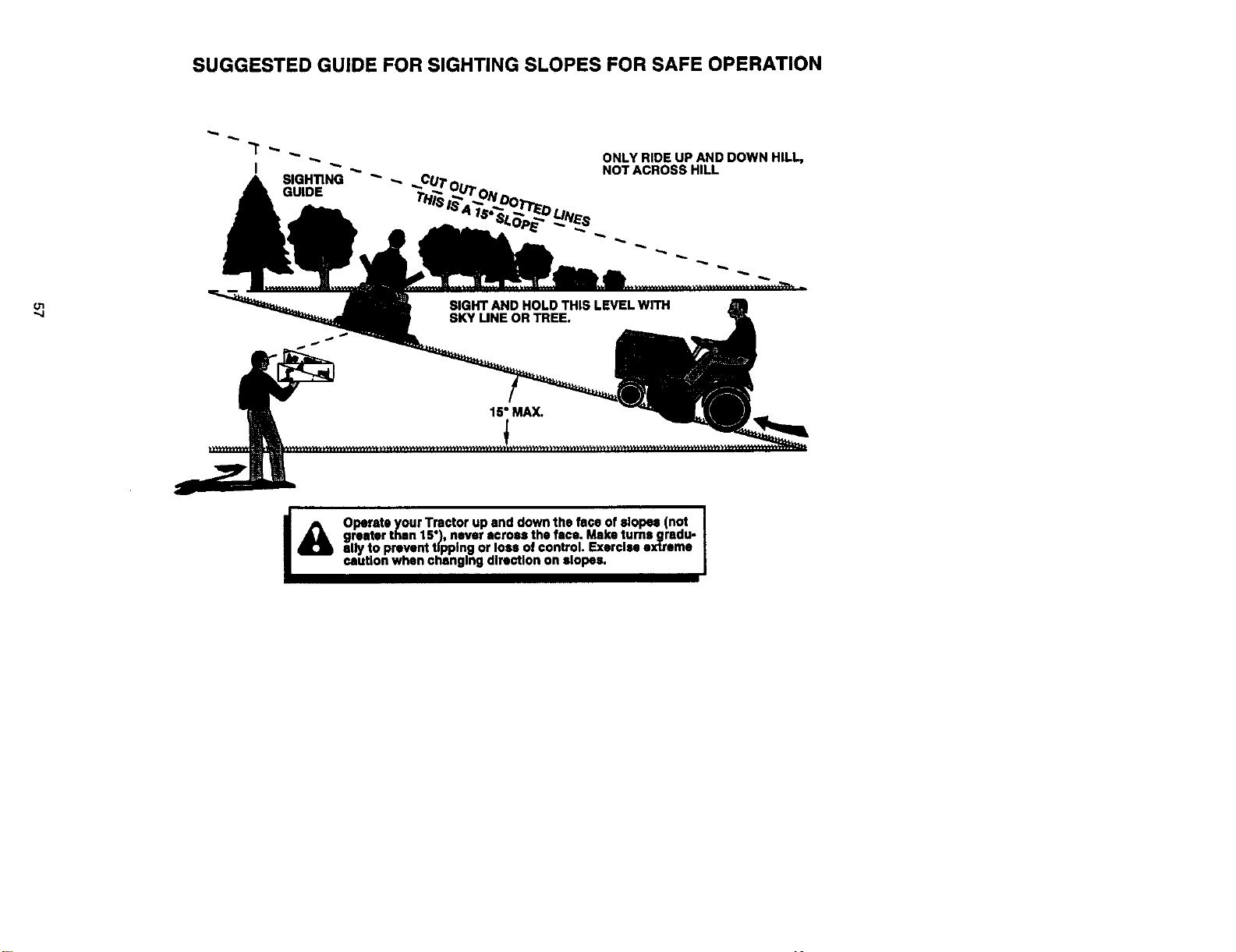
SUGGESTED GUIDE FOR SIGHTING SLOPES FOR SAFE OPERATION
ONLY RIDE UP AND DOWN HILL,
NOT ACROSS HILL
I_ Operate your Tractor up and down the face of slopes (not I
i
greater than 15"),never across the face. Make turns _radu-
I
ally to prevent tipping or loss ofcontrol. Exercise axtrame
caution when changing direction on slopes.

58

59

For the repair or replacement parts you need
delivered directly to your home
Call 7 am - 7 pm, 7 days a week
1-800-366-PART
(1-60o-3ss-7278)
Para ordenar pJezas con entrega a
domicilio- 1-800-659-7084
For in-house major brand repair service
Call 24 hoursa day, 7 days a week
1-800-4-REPAIR
(1-800-473-7274)
Para pedir servicio de reparaci6n a
domicilio - 1-800-676-5811
For the locationof a Sears Parts and
Repair Center in your area
Call 24 hoursa day, 7 days a week
1-800-488-1222
For information on purchasing a Sears
Maintenance Agreement or to inquire
about an existing Agreement
Call 9 am - 5 pm, Monday-Saturday
1-800-827-6655
Whenrequestingserviceorordering
parts,alwaysprovidethefollowing
information:
• ProductType • PartNumber
• ModelNumber • PartDescription
SEARS
America'sRepair Special_ts
165430 Rev. 3 7.29.98 TR/RH Printed in U.S.A.


