Loading ...
Loading ...
Loading ...
22 23
CHECKING THE GAS SUPPLY
1. Check the manometer zero point is correct.
2. Connect the manometer to the cooktop pressure point.
This is located on the regulator.
3. Turn on the gas supply and electricity and try to
ignite the gas.
NOTE! It will take additional time to light the gas for the first
time as air needs to be purged from the pipes.
4. With the appliance operating check the outlet pressure
• when all burners of the appliance are operating
at maximum,
• when the smallest burner of the appliance is
operating at minimum.
Under these conditions the outlet pressure should not
vary from the nominal outlet pressure of 1.00kPa by
more than ±0.20kPa.
If the regulator appears to not be performing satisfactorily,
then check the following points:
1. If the outlet pressure is consistently too low then the inlet
pressure may be too low and adjustment of an upstream
regulator may be needed, or an upstream regulator or
valve with insufficient flow capacity may be present in
the gas supply line. If this is suspected then it may be
necessary to repeat the checks whilst measuring both
the inlet and outlet pressure to determine if the inlet
pressure is in the range
1.13 – 5kPa.
2. Check that the regulator has been fitted to the gas
supply line in the correct orientation, the arrow on the
base of the body indicates the direction of gas flow.
Once these checks have been completed, if the
regulator still fails to perform in a satisfactory manner it should
be replaced.
Table 3
burner type
natural gas (nominal test point pressure: 1.00kPa)
LPG (nominal test point pressure:
2.60kPa)
injector size
(mm)
gas consumption (MJ/h)
injector size
(mm)
gas consumption
(MJ/h)
Small burner 1.00 5.1 0.55 4.0
Medium burner 1.35 9.0 0.70 6.5
Large burner 1.60 12 .1 0.90 10.7
Dual Wok 19MJ 0.96 + 3 x 1.07 19.0 0.52 + 3 x 0.58 17.0
Wok 14.4MJ 1.75 14.4 1.0 13
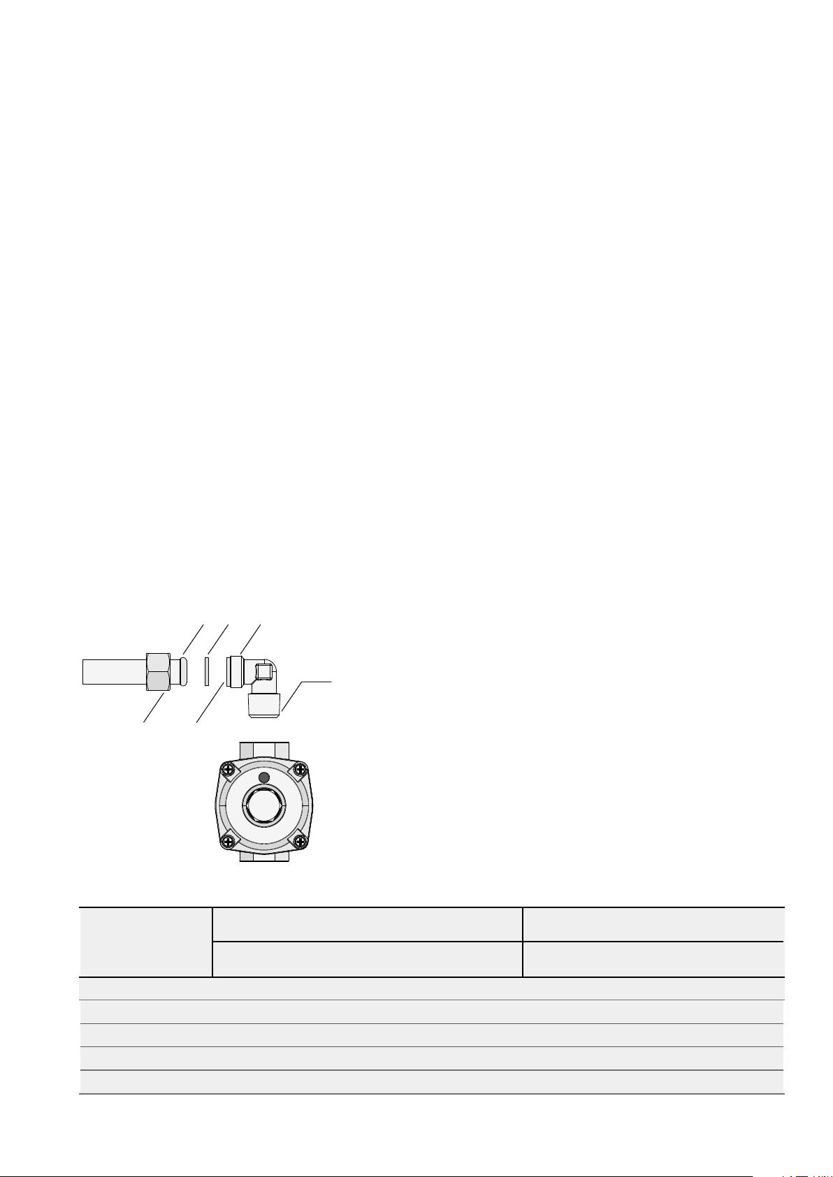
Assembly of the regulator
The assembly of the regulator to the cooktop manifold is
achieved via the elbow union and sealing washer supplied,
refer to figure 8.
The ½” parallel thread connects to the manifold, and the
sealing washer is placed between the manifold end and
the flat face on the elbow.
The ½” tapered thread connects to the outlet of
the regulator, and is sealed on the thread using approved
thread sealing tape or approved thread sealing compound.
The inlet of the regulator is a ½” parallel thread and
is connected to consumer piping or hose assembly.
Regulators are supplied pre-adjusted and configured
by the component maker for use with Natural Gas.
The appliance installer is not required to make an
adjustment to obtain the correct outlet pressure setting.
An arrow on the base of the regulator indicates the
direction of gas flow when the inlet and outlet of the
regulator is orientated correctly. When the regulator has
been fitted check for leaks from the connections with
soapy water.
Figure 8
½” tapered thread
seal using approved
sealing tape or
approved thread
sealing compound
manifold
endform
female nut flat face
sealing
washer
½” parallel
thread
regulator
outlet
inlet
GAS CONNECTION (CONTINUED)
LPG CONVERSION
This appliance is supplied set up for Natural Gas usage.
A conversion kit is included with the product for Universal
LPG usage. The conversion kit contains the appropriate
injectors and 1 LPG sticker.
Please follow the procedure below if a conversion to suit
UNIVERSAL LPG is required:
1. Remove the hotplate trivets, burner caps and burner
crowns to access the hotplate injectors. Replace the
factory fitted injectors with the appropriate injectors,
as supplied. Refer to injector orifice table for injector
sizes. The injector size is stamped on the side of the
injector.
2. Unscrew the top hat nut from the regulator. The top
hat nut and control pressure spring assembly will
disengage as an assembly.
3. Unscrew the threaded pin from top hat.
4. Upturn threaded pin, so spring is free and screw pin
back into the top hat until firm.
5. Refit the top hat nut assembly to the regulator
ensuring that it is fully screwed down. The regulator is
now set for connection to LPG.
6. Turn on the gas supply and at each new connection
check for leaks using soapy water. Each hotplate
valve should be turned on, one at a time, and the
injector hole blanked off for several seconds.
7. The operation of the regulator can be confirmed by
connecting a manometer to the pressure test point
located on the side of the regulator body adjacent to
the outlet.
With the appliance operating check the outlet
pressure when all burners of the appliance are
operating at maximum, when the smallest burner of
the appliance is operating at minimum.
Under these conditions the outlet pressure should
not vary from the nominal outlet pressure of 2.60kPa
by more than ±0.52kPa.
8. If the regulator appears to not be performing
satisfactorily then check the following points:
If the outlet pressure is consistently too low then the
inlet pressure may be too low and adjustment of an
upstream regulator may be needed, or an upstream
regulator or valve with insufficient flow capacity may
be present in the gas supply line.
If this is suspected then it may be necessary to
repeat the checks whilst measuring both the inlet and
outlet pressure to determine if the inlet pressure is in
the range 2.75 – 7.00kPa.
Check that the insert has been fitted correctly.
Check that the turret screw is fully screwed down.
Check that the regulator has been fitted to the gas
supply line in the correct orientation, the arrow on the
base of the body indicates the direction of gas flow.
Once these checks have been completed, if the
regulator still fails to perform in a satisfactory manner
it should be replaced.
9. One by one, turn the knobs to minimum and screw
in the bypass screw (accessible when the knob is
removed) until a small stable flame results. Turn the
knob to maximum and then back to minimum to
ensure that the correct minimum flame is maintained.
10. Attach the LPG sticker to the cooker, near the gas
supply inlet. Cover the Natural Gas label that is
factory fitted.
A B
turn top hat nut
anti-clockwise
and remove
top hat nut assembly
fully screwed down
G H
C D
configuration for natural gas
E F
configuration for LPG
bypass screw
control knob shaft
flame size adjusted to minimum
flame size adjusted to maximum
Loading ...
Loading ...
Loading ...