
VEVOR
Pipe Stand
Operating Instructions and Parts Manual
Please read and save these instructions. Read through this owner's manual
carefully before using product. Protect yourself and others by observing all
safety information, warnings, and cautions. Failure to comply with instructions
could result in personal injury and/or damage to product or property. Please
retain instructions for future reference.
Description
Designed to support pipes for a variety of uses. Do not exceed the maximum
capacity of the product.
Inspection/Maintenance
Carefully inspect the stand prior to each use for proper assembly (such as
the hand screw), wear, damage, or other issues that may affect safe usage.
If any problems are found, discontinue use until the stand is repaired. Keep
the stand clean and all moving parts lightly lubricated to aid in operation.
Operating Instructions and Parts Manual
General Safety Information
WARNING Read the warnings and instructions for all equipment being used
before operating this tool to reduce the risk of serious personal injury.
WARNING Failure to properly support the pipe may result in tipping of the
stand, dropping of the pipe, or serious injuries.
WARNING Use the appropriate safety equipment for the intended job such
as eye protection,hearing protection, feet protection, dusk masks, face shields,
etc to reduce the risk of injuries.
Installation and Operation
1. Make sure that all equipment is inspected and set up accordingly.
2. Make sure that the ground below the pipe stand is clear, stable, and level.
3.The legs of the pipe stand should be fully open and the feet placed squarely on
the floor.
4. if the stand is equipped with rollers, ensure the rollers are properly adjusted for
the pipe size
5. Fasteners on the pipe stand should be evaluated and ensure that they are
secured
6.To adjust the height. grip head assembly, loosen the hand screw, and raise the
lock ring to disengage the elevator tube. Move the head assembly to the desired
height. Next, lower the lock ring until it engages the elevator tube, and securely
tighten the hand screw. Do not raise the elevator tube past the hand screw or past
the unit specifications. The jack screw can be used for fine adjustments to height.
Do so by holding the head of the assembly station and carefully turning the jack
screw handle to the desired height. Do not force the jack screw handle, as it may
cause the screw to come loose from the stand.
7. Position the stand(s) to properly support the pipe. The pipe should be supported
in at least two places at all times. The number and placement of stands depends
on the size, length, and weight of the pipe length.
8.Carefully place the pipe on the stands. Make sure the pipe is properly centered
on the stands to reduce the risk of tipping. Always stay clear of the supported load.
Attention
:
Make sure you can
always see the
screw through the
observation holes.
D
o
n
o
t
exceed the
maximum
line of the
inner tube.
Tighten
the safety
nut can be
more
security
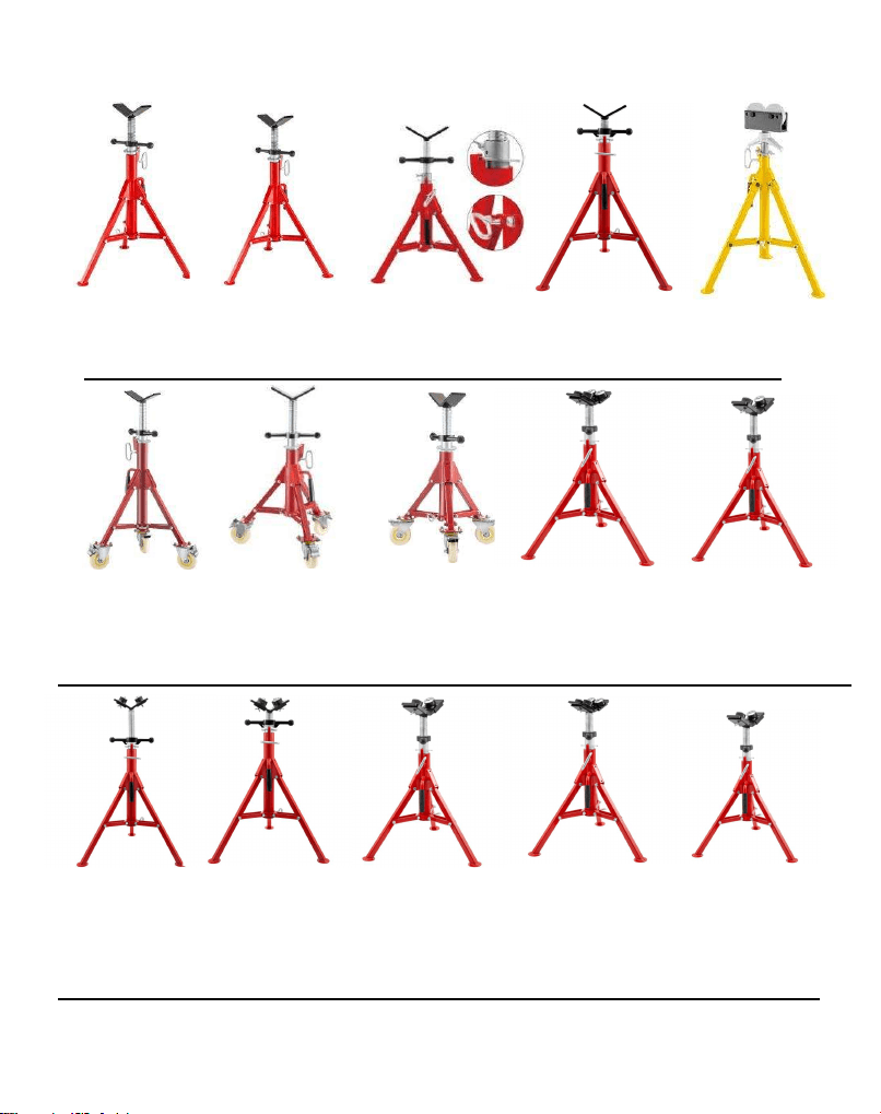
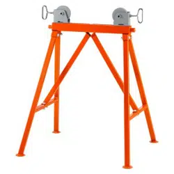
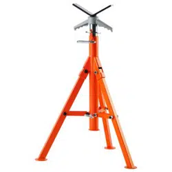
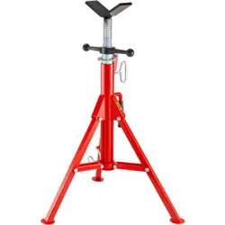
Pipe Jack Stand Pipe Jack Stand Pipe Jack Stand Pipe Jack Stand Pipe Jack Stand
With V-Head With V-Head With V-Head With V-Head With Roller-Head
1107 1107B 1107C 1107S 1109
V-Head Pipe V-Head Pipe V-Head Pipe V-Head Pipe V-Head Pipe
Jack Stand Jack Stand Jack Stand Jack Stand Jack Stand
with Casters with Casters with Casters With 4-Ball With 2-Ball
1107AV 1107BV 1107CV 1107B4-BALL 1107C2-BALL
V-Head Pipe V-Head Pipe V-Head Pipe V-Head Pipe V-Head Pipe
Jack Stand Jack Stand Jack Stand Jack Stand Jack Stand
With 2-Ball With 4-Ball With 2-Ball With 4-Ball With 2-Ball
1107S2-BALL 1107S4-BALL 1107A2-BALL 1107A4-BALL 1107B2-BALL
V-Head Pipe Jack V- Roller Head Mul-Function
Stand With 2-Ball Pipe Stand Jaw Stand
1107C4-BALL 1106 1108
Part Number Pipe Capacity(In.) Max Weight Capacity Overall Height (In.)
1107 1/8 To 12 2500 lbs 28” To 52”
1107A2-BALL 1/8 To 12 1300lbs 28” To 52”
1107A4-BALL 1/8 To 12 1500lbs 28” To 52”
1107B 1/8 To 12 2500lbs 24” To 42”
1107B2-BALL 1/8 To 12 1300lbs 24” To 42”
1107B4-BALL 1/8 To 12 1500lbs 24” To 42”
1107C 1/8 To 12 2500lbs 20” To 37”
1107C2-BALL 1/8 To 12 1300lbs 20” To 37”
1107C4-BALL 1/8 To 12 1500lbs 20” To 37”
1107S 1/8 To 12 2500lbs 28” To 52”
1107S2-BALL 1/8 To 12 1300lbs 28” To 52”
1107S4-BALL 1/8 To 12 1500lbs 28” To 52”
1109 1/8 To 12 2500lbs 32” To 55”
1106 1/8 To 24 3000lbs 28” To 52”
1108 300lbs 32” To 45”