Loading ...
Loading ...
Loading ...
ENGLISH
7
Guards
CAUTION: Guards must be used with all grinding
wheels, cutting wheels and sanding flap discs.
The tool may be used without a guard only when
sanding with conventional sanding discs. Some
applications may require purchasing the correct guard
from your local dealer or authorized servicecenter.
NOTE: Edge grinding and cutting can be performed with
Type 27 wheels designed and specified for this purpose;
1/4" (6.35 mm) thick wheels are designed for surface
grinding while thinner Type 27 wheels need to be examined
for the manufacturer's label to see if they can be used for
surface grinding or only edge grinding/cutting.
NOTE: See the Accessories Chart to select the proper
guard/accessorycombination.
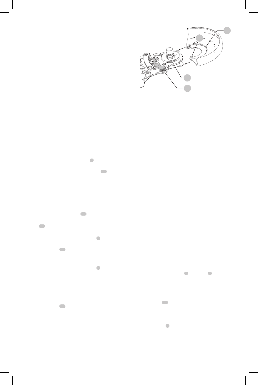
Adjusting and Mounting Guard (Fig. D)
WARNING: To reduce the risk of serious personal
injury, turn tool off and disconnect battery pack
before making any adjustments or removing/
installing attachments or accessories. An
accidental start-up can causeinjury.
Adjustment Options
Press and hold the guard release lever
9
. Rotate the guard
into the desired workingposition. The guard release lever
should snap into one of the alignment holes
13
on the
guard collar. This ensures that the guard issecure.
Mounting Guard (Fig. D)
CAUTION: Prior to mounting guard, ensure the screw,
lever, and spring are fitted correctly before mounting
theguard.
1. With the spindle facing the operator, align the guard
parallel to the mounting slot
11
ingearcase.
2. Slide the guard into the mounting slot with the guard
tabs
12
riding along the 2 flat sides of the collar just
above the mountingslot.
3. Press and hold the guard release lever
9
and rotate
the guard around until the lever engages one of the
alignmentholes
13
.
4. Release the guard releaselever.
5. To position the guard:
Press and hold the guard release lever
9
. Rotate the
guard clockwise or anti-clockwise into the desired
working position.
NOTE: The guard body should be positioned between
the spindle and the operator to provide maximum
operatorprotection.
The guard release lever should snap into one of the
alignment holes
13
on the guard collar. This ensures
that the guard issecure.
6. To remove the guard, press and hold the guard release
lever and rotate the guard around until the lever
disengages from the alignmentholes, then slide the
guard off the mountingslot.
Fig. D
11
13
9
12
Flanges and Wheels
WARNING: To reduce the risk of serious personal
injury, turn unit off and disconnect it from
power source before making any adjustments or
removing/installing attachments or accessories.
An accidental start-up can causeinjury.
WARNING: Hubbed wheels are not to be used
on this grinder since the grinding surface of
the wheel might not be within the guard lip.
An improperly mounted hubbed wheel that projects
through the plane of the guard lip cannot be
adequately protected.
Mounting Non-Hubbed Wheels (Fig. E)
WARNING: Failure to properly seat the flanges and/or
wheel could result in serious injury (or damage to the
tool orwheel).
CAUTION: Included flanges must be used with
depressed center Type 27/42 grinding wheels and
Type1/41 cutting wheels. See the Accessories Chart
for moreinformation.
WARNING: A closed, two-sided cutting wheel guard
is required when using abrasive cutting wheels or
diamond coated cuttingwheels.
WARNING: Use of a damaged flange or guard or
failure to use proper flange and guard can re sult in
injury due to wheel breakage and wheel contact. See
the Accessories Chart for moreinformation.
All grinding wheels must use included flanges. Refer to
Accessories Chart for moreinformation.
1. Install the backing flange
6
on spindle
4
with the
raised section (pilot) against the wheel. Be sure the
backing flange recess is seated onto the flats of the
spindle by pushing and twisting the flange before
placingwheel.
2. Place wheel
14
against the backing flange, centering
the wheel on the raised section (pilot) of the
backingflange.
3. While depressing the spindle lock button, thread the
locking flange
7
on spindle. If the wheel you are
installing is more than 3.0 mm (1/8") thick, place the
locking flange on the spindle so that the raised section
(pilot) fits into the center of the wheel. If the wheel you
are installing is 3.0 mm (1/8") thick or less, place the
locking flange on the spindle so that the raised section
(pilot) is not against thewheel.
Loading ...
Loading ...
Loading ...